EP2886305A1 - Verbund - Google Patents
Verbund Download PDFInfo
- Publication number
- EP2886305A1 EP2886305A1 EP13198709.1A EP13198709A EP2886305A1 EP 2886305 A1 EP2886305 A1 EP 2886305A1 EP 13198709 A EP13198709 A EP 13198709A EP 2886305 A1 EP2886305 A1 EP 2886305A1
- Authority
- EP
- European Patent Office
- Prior art keywords
- thermoplastic
- rivet
- continuous fiber
- reinforced
- polyamide
- Prior art date
- Legal status (The legal status is an assumption and is not a legal conclusion. Google has not performed a legal analysis and makes no representation as to the accuracy of the status listed.)
- Granted
Links
Images


Classifications
-
- B—PERFORMING OPERATIONS; TRANSPORTING
- B29—WORKING OF PLASTICS; WORKING OF SUBSTANCES IN A PLASTIC STATE IN GENERAL
- B29C—SHAPING OR JOINING OF PLASTICS; SHAPING OF MATERIAL IN A PLASTIC STATE, NOT OTHERWISE PROVIDED FOR; AFTER-TREATMENT OF THE SHAPED PRODUCTS, e.g. REPAIRING
- B29C65/00—Joining or sealing of preformed parts, e.g. welding of plastics materials; Apparatus therefor
- B29C65/02—Joining or sealing of preformed parts, e.g. welding of plastics materials; Apparatus therefor by heating, with or without pressure
- B29C65/08—Joining or sealing of preformed parts, e.g. welding of plastics materials; Apparatus therefor by heating, with or without pressure using ultrasonic vibrations
-
- B—PERFORMING OPERATIONS; TRANSPORTING
- B29—WORKING OF PLASTICS; WORKING OF SUBSTANCES IN A PLASTIC STATE IN GENERAL
- B29C—SHAPING OR JOINING OF PLASTICS; SHAPING OF MATERIAL IN A PLASTIC STATE, NOT OTHERWISE PROVIDED FOR; AFTER-TREATMENT OF THE SHAPED PRODUCTS, e.g. REPAIRING
- B29C65/00—Joining or sealing of preformed parts, e.g. welding of plastics materials; Apparatus therefor
- B29C65/02—Joining or sealing of preformed parts, e.g. welding of plastics materials; Apparatus therefor by heating, with or without pressure
- B29C65/10—Joining or sealing of preformed parts, e.g. welding of plastics materials; Apparatus therefor by heating, with or without pressure using hot gases (e.g. combustion gases) or flames coming in contact with at least one of the parts to be joined
-
- B—PERFORMING OPERATIONS; TRANSPORTING
- B29—WORKING OF PLASTICS; WORKING OF SUBSTANCES IN A PLASTIC STATE IN GENERAL
- B29C—SHAPING OR JOINING OF PLASTICS; SHAPING OF MATERIAL IN A PLASTIC STATE, NOT OTHERWISE PROVIDED FOR; AFTER-TREATMENT OF THE SHAPED PRODUCTS, e.g. REPAIRING
- B29C65/00—Joining or sealing of preformed parts, e.g. welding of plastics materials; Apparatus therefor
- B29C65/56—Joining or sealing of preformed parts, e.g. welding of plastics materials; Apparatus therefor using mechanical means or mechanical connections, e.g. form-fits
- B29C65/60—Riveting or staking
- B29C65/606—Riveting or staking the rivets being integral with one of the parts to be joined, i.e. staking
-
- B—PERFORMING OPERATIONS; TRANSPORTING
- B29—WORKING OF PLASTICS; WORKING OF SUBSTANCES IN A PLASTIC STATE IN GENERAL
- B29C—SHAPING OR JOINING OF PLASTICS; SHAPING OF MATERIAL IN A PLASTIC STATE, NOT OTHERWISE PROVIDED FOR; AFTER-TREATMENT OF THE SHAPED PRODUCTS, e.g. REPAIRING
- B29C65/00—Joining or sealing of preformed parts, e.g. welding of plastics materials; Apparatus therefor
- B29C65/74—Joining or sealing of preformed parts, e.g. welding of plastics materials; Apparatus therefor by welding and severing, or by joining and severing, the severing being performed in the area to be joined, next to the area to be joined, in the joint area or next to the joint area
-
- B—PERFORMING OPERATIONS; TRANSPORTING
- B29—WORKING OF PLASTICS; WORKING OF SUBSTANCES IN A PLASTIC STATE IN GENERAL
- B29C—SHAPING OR JOINING OF PLASTICS; SHAPING OF MATERIAL IN A PLASTIC STATE, NOT OTHERWISE PROVIDED FOR; AFTER-TREATMENT OF THE SHAPED PRODUCTS, e.g. REPAIRING
- B29C66/00—General aspects of processes or apparatus for joining preformed parts
- B29C66/01—General aspects dealing with the joint area or with the area to be joined
- B29C66/02—Preparation of the material, in the area to be joined, prior to joining or welding
- B29C66/024—Thermal pre-treatments
- B29C66/0242—Heating, or preheating, e.g. drying
-
- B—PERFORMING OPERATIONS; TRANSPORTING
- B29—WORKING OF PLASTICS; WORKING OF SUBSTANCES IN A PLASTIC STATE IN GENERAL
- B29C—SHAPING OR JOINING OF PLASTICS; SHAPING OF MATERIAL IN A PLASTIC STATE, NOT OTHERWISE PROVIDED FOR; AFTER-TREATMENT OF THE SHAPED PRODUCTS, e.g. REPAIRING
- B29C66/00—General aspects of processes or apparatus for joining preformed parts
- B29C66/01—General aspects dealing with the joint area or with the area to be joined
- B29C66/05—Particular design of joint configurations
- B29C66/10—Particular design of joint configurations particular design of the joint cross-sections
- B29C66/11—Joint cross-sections comprising a single joint-segment, i.e. one of the parts to be joined comprising a single joint-segment in the joint cross-section
- B29C66/112—Single lapped joints
-
- B—PERFORMING OPERATIONS; TRANSPORTING
- B29—WORKING OF PLASTICS; WORKING OF SUBSTANCES IN A PLASTIC STATE IN GENERAL
- B29C—SHAPING OR JOINING OF PLASTICS; SHAPING OF MATERIAL IN A PLASTIC STATE, NOT OTHERWISE PROVIDED FOR; AFTER-TREATMENT OF THE SHAPED PRODUCTS, e.g. REPAIRING
- B29C66/00—General aspects of processes or apparatus for joining preformed parts
- B29C66/01—General aspects dealing with the joint area or with the area to be joined
- B29C66/05—Particular design of joint configurations
- B29C66/10—Particular design of joint configurations particular design of the joint cross-sections
- B29C66/11—Joint cross-sections comprising a single joint-segment, i.e. one of the parts to be joined comprising a single joint-segment in the joint cross-section
- B29C66/114—Single butt joints
-
- B—PERFORMING OPERATIONS; TRANSPORTING
- B29—WORKING OF PLASTICS; WORKING OF SUBSTANCES IN A PLASTIC STATE IN GENERAL
- B29C—SHAPING OR JOINING OF PLASTICS; SHAPING OF MATERIAL IN A PLASTIC STATE, NOT OTHERWISE PROVIDED FOR; AFTER-TREATMENT OF THE SHAPED PRODUCTS, e.g. REPAIRING
- B29C66/00—General aspects of processes or apparatus for joining preformed parts
- B29C66/01—General aspects dealing with the joint area or with the area to be joined
- B29C66/05—Particular design of joint configurations
- B29C66/20—Particular design of joint configurations particular design of the joint lines, e.g. of the weld lines
- B29C66/21—Particular design of joint configurations particular design of the joint lines, e.g. of the weld lines said joint lines being formed by a single dot or dash or by several dots or dashes, i.e. spot joining or spot welding
-
- B—PERFORMING OPERATIONS; TRANSPORTING
- B29—WORKING OF PLASTICS; WORKING OF SUBSTANCES IN A PLASTIC STATE IN GENERAL
- B29C—SHAPING OR JOINING OF PLASTICS; SHAPING OF MATERIAL IN A PLASTIC STATE, NOT OTHERWISE PROVIDED FOR; AFTER-TREATMENT OF THE SHAPED PRODUCTS, e.g. REPAIRING
- B29C66/00—General aspects of processes or apparatus for joining preformed parts
- B29C66/50—General aspects of joining tubular articles; General aspects of joining long products, i.e. bars or profiled elements; General aspects of joining single elements to tubular articles, hollow articles or bars; General aspects of joining several hollow-preforms to form hollow or tubular articles
- B29C66/51—Joining tubular articles, profiled elements or bars; Joining single elements to tubular articles, hollow articles or bars; Joining several hollow-preforms to form hollow or tubular articles
- B29C66/53—Joining single elements to tubular articles, hollow articles or bars
- B29C66/534—Joining single elements to open ends of tubular or hollow articles or to the ends of bars
- B29C66/5346—Joining single elements to open ends of tubular or hollow articles or to the ends of bars said single elements being substantially flat
-
- B—PERFORMING OPERATIONS; TRANSPORTING
- B29—WORKING OF PLASTICS; WORKING OF SUBSTANCES IN A PLASTIC STATE IN GENERAL
- B29C—SHAPING OR JOINING OF PLASTICS; SHAPING OF MATERIAL IN A PLASTIC STATE, NOT OTHERWISE PROVIDED FOR; AFTER-TREATMENT OF THE SHAPED PRODUCTS, e.g. REPAIRING
- B29C66/00—General aspects of processes or apparatus for joining preformed parts
- B29C66/70—General aspects of processes or apparatus for joining preformed parts characterised by the composition, physical properties or the structure of the material of the parts to be joined; Joining with non-plastics material
- B29C66/72—General aspects of processes or apparatus for joining preformed parts characterised by the composition, physical properties or the structure of the material of the parts to be joined; Joining with non-plastics material characterised by the structure of the material of the parts to be joined
- B29C66/721—Fibre-reinforced materials
- B29C66/7214—Fibre-reinforced materials characterised by the length of the fibres
- B29C66/72141—Fibres of continuous length
-
- B—PERFORMING OPERATIONS; TRANSPORTING
- B29—WORKING OF PLASTICS; WORKING OF SUBSTANCES IN A PLASTIC STATE IN GENERAL
- B29C—SHAPING OR JOINING OF PLASTICS; SHAPING OF MATERIAL IN A PLASTIC STATE, NOT OTHERWISE PROVIDED FOR; AFTER-TREATMENT OF THE SHAPED PRODUCTS, e.g. REPAIRING
- B29C66/00—General aspects of processes or apparatus for joining preformed parts
- B29C66/70—General aspects of processes or apparatus for joining preformed parts characterised by the composition, physical properties or the structure of the material of the parts to be joined; Joining with non-plastics material
- B29C66/73—General aspects of processes or apparatus for joining preformed parts characterised by the composition, physical properties or the structure of the material of the parts to be joined; Joining with non-plastics material characterised by the intensive physical properties of the material of the parts to be joined, by the optical properties of the material of the parts to be joined, by the extensive physical properties of the parts to be joined, by the state of the material of the parts to be joined or by the material of the parts to be joined being a thermoplastic or a thermoset
- B29C66/739—General aspects of processes or apparatus for joining preformed parts characterised by the composition, physical properties or the structure of the material of the parts to be joined; Joining with non-plastics material characterised by the intensive physical properties of the material of the parts to be joined, by the optical properties of the material of the parts to be joined, by the extensive physical properties of the parts to be joined, by the state of the material of the parts to be joined or by the material of the parts to be joined being a thermoplastic or a thermoset characterised by the material of the parts to be joined being a thermoplastic or a thermoset
- B29C66/7392—General aspects of processes or apparatus for joining preformed parts characterised by the composition, physical properties or the structure of the material of the parts to be joined; Joining with non-plastics material characterised by the intensive physical properties of the material of the parts to be joined, by the optical properties of the material of the parts to be joined, by the extensive physical properties of the parts to be joined, by the state of the material of the parts to be joined or by the material of the parts to be joined being a thermoplastic or a thermoset characterised by the material of the parts to be joined being a thermoplastic or a thermoset characterised by the material of at least one of the parts being a thermoplastic
-
- B—PERFORMING OPERATIONS; TRANSPORTING
- B29—WORKING OF PLASTICS; WORKING OF SUBSTANCES IN A PLASTIC STATE IN GENERAL
- B29C—SHAPING OR JOINING OF PLASTICS; SHAPING OF MATERIAL IN A PLASTIC STATE, NOT OTHERWISE PROVIDED FOR; AFTER-TREATMENT OF THE SHAPED PRODUCTS, e.g. REPAIRING
- B29C66/00—General aspects of processes or apparatus for joining preformed parts
- B29C66/80—General aspects of machine operations or constructions and parts thereof
- B29C66/81—General aspects of the pressing elements, i.e. the elements applying pressure on the parts to be joined in the area to be joined, e.g. the welding jaws or clamps
- B29C66/814—General aspects of the pressing elements, i.e. the elements applying pressure on the parts to be joined in the area to be joined, e.g. the welding jaws or clamps characterised by the design of the pressing elements, e.g. of the welding jaws or clamps
- B29C66/8141—General aspects of the pressing elements, i.e. the elements applying pressure on the parts to be joined in the area to be joined, e.g. the welding jaws or clamps characterised by the design of the pressing elements, e.g. of the welding jaws or clamps characterised by the surface geometry of the part of the pressing elements, e.g. welding jaws or clamps, coming into contact with the parts to be joined
- B29C66/81411—General aspects of the pressing elements, i.e. the elements applying pressure on the parts to be joined in the area to be joined, e.g. the welding jaws or clamps characterised by the design of the pressing elements, e.g. of the welding jaws or clamps characterised by the surface geometry of the part of the pressing elements, e.g. welding jaws or clamps, coming into contact with the parts to be joined characterised by its cross-section, e.g. transversal or longitudinal, being non-flat
- B29C66/81421—General aspects of the pressing elements, i.e. the elements applying pressure on the parts to be joined in the area to be joined, e.g. the welding jaws or clamps characterised by the design of the pressing elements, e.g. of the welding jaws or clamps characterised by the surface geometry of the part of the pressing elements, e.g. welding jaws or clamps, coming into contact with the parts to be joined characterised by its cross-section, e.g. transversal or longitudinal, being non-flat being convex or concave
- B29C66/81423—General aspects of the pressing elements, i.e. the elements applying pressure on the parts to be joined in the area to be joined, e.g. the welding jaws or clamps characterised by the design of the pressing elements, e.g. of the welding jaws or clamps characterised by the surface geometry of the part of the pressing elements, e.g. welding jaws or clamps, coming into contact with the parts to be joined characterised by its cross-section, e.g. transversal or longitudinal, being non-flat being convex or concave being concave
-
- B—PERFORMING OPERATIONS; TRANSPORTING
- B29—WORKING OF PLASTICS; WORKING OF SUBSTANCES IN A PLASTIC STATE IN GENERAL
- B29C—SHAPING OR JOINING OF PLASTICS; SHAPING OF MATERIAL IN A PLASTIC STATE, NOT OTHERWISE PROVIDED FOR; AFTER-TREATMENT OF THE SHAPED PRODUCTS, e.g. REPAIRING
- B29C66/00—General aspects of processes or apparatus for joining preformed parts
- B29C66/80—General aspects of machine operations or constructions and parts thereof
- B29C66/83—General aspects of machine operations or constructions and parts thereof characterised by the movement of the joining or pressing tools
- B29C66/832—Reciprocating joining or pressing tools
- B29C66/8322—Joining or pressing tools reciprocating along one axis
-
- B—PERFORMING OPERATIONS; TRANSPORTING
- B29—WORKING OF PLASTICS; WORKING OF SUBSTANCES IN A PLASTIC STATE IN GENERAL
- B29C—SHAPING OR JOINING OF PLASTICS; SHAPING OF MATERIAL IN A PLASTIC STATE, NOT OTHERWISE PROVIDED FOR; AFTER-TREATMENT OF THE SHAPED PRODUCTS, e.g. REPAIRING
- B29C2793/00—Shaping techniques involving a cutting or machining operation
- B29C2793/0045—Perforating
-
- B—PERFORMING OPERATIONS; TRANSPORTING
- B29—WORKING OF PLASTICS; WORKING OF SUBSTANCES IN A PLASTIC STATE IN GENERAL
- B29C—SHAPING OR JOINING OF PLASTICS; SHAPING OF MATERIAL IN A PLASTIC STATE, NOT OTHERWISE PROVIDED FOR; AFTER-TREATMENT OF THE SHAPED PRODUCTS, e.g. REPAIRING
- B29C65/00—Joining or sealing of preformed parts, e.g. welding of plastics materials; Apparatus therefor
- B29C65/02—Joining or sealing of preformed parts, e.g. welding of plastics materials; Apparatus therefor by heating, with or without pressure
- B29C65/14—Joining or sealing of preformed parts, e.g. welding of plastics materials; Apparatus therefor by heating, with or without pressure using wave energy, i.e. electromagnetic radiation, or particle radiation
- B29C65/1403—Joining or sealing of preformed parts, e.g. welding of plastics materials; Apparatus therefor by heating, with or without pressure using wave energy, i.e. electromagnetic radiation, or particle radiation characterised by the type of electromagnetic or particle radiation
- B29C65/1412—Infrared [IR] radiation
-
- B—PERFORMING OPERATIONS; TRANSPORTING
- B29—WORKING OF PLASTICS; WORKING OF SUBSTANCES IN A PLASTIC STATE IN GENERAL
- B29C—SHAPING OR JOINING OF PLASTICS; SHAPING OF MATERIAL IN A PLASTIC STATE, NOT OTHERWISE PROVIDED FOR; AFTER-TREATMENT OF THE SHAPED PRODUCTS, e.g. REPAIRING
- B29C66/00—General aspects of processes or apparatus for joining preformed parts
- B29C66/70—General aspects of processes or apparatus for joining preformed parts characterised by the composition, physical properties or the structure of the material of the parts to be joined; Joining with non-plastics material
- B29C66/71—General aspects of processes or apparatus for joining preformed parts characterised by the composition, physical properties or the structure of the material of the parts to be joined; Joining with non-plastics material characterised by the composition of the plastics material of the parts to be joined
-
- B—PERFORMING OPERATIONS; TRANSPORTING
- B29—WORKING OF PLASTICS; WORKING OF SUBSTANCES IN A PLASTIC STATE IN GENERAL
- B29C—SHAPING OR JOINING OF PLASTICS; SHAPING OF MATERIAL IN A PLASTIC STATE, NOT OTHERWISE PROVIDED FOR; AFTER-TREATMENT OF THE SHAPED PRODUCTS, e.g. REPAIRING
- B29C66/00—General aspects of processes or apparatus for joining preformed parts
- B29C66/70—General aspects of processes or apparatus for joining preformed parts characterised by the composition, physical properties or the structure of the material of the parts to be joined; Joining with non-plastics material
- B29C66/73—General aspects of processes or apparatus for joining preformed parts characterised by the composition, physical properties or the structure of the material of the parts to be joined; Joining with non-plastics material characterised by the intensive physical properties of the material of the parts to be joined, by the optical properties of the material of the parts to be joined, by the extensive physical properties of the parts to be joined, by the state of the material of the parts to be joined or by the material of the parts to be joined being a thermoplastic or a thermoset
- B29C66/739—General aspects of processes or apparatus for joining preformed parts characterised by the composition, physical properties or the structure of the material of the parts to be joined; Joining with non-plastics material characterised by the intensive physical properties of the material of the parts to be joined, by the optical properties of the material of the parts to be joined, by the extensive physical properties of the parts to be joined, by the state of the material of the parts to be joined or by the material of the parts to be joined being a thermoplastic or a thermoset characterised by the material of the parts to be joined being a thermoplastic or a thermoset
- B29C66/7392—General aspects of processes or apparatus for joining preformed parts characterised by the composition, physical properties or the structure of the material of the parts to be joined; Joining with non-plastics material characterised by the intensive physical properties of the material of the parts to be joined, by the optical properties of the material of the parts to be joined, by the extensive physical properties of the parts to be joined, by the state of the material of the parts to be joined or by the material of the parts to be joined being a thermoplastic or a thermoset characterised by the material of the parts to be joined being a thermoplastic or a thermoset characterised by the material of at least one of the parts being a thermoplastic
- B29C66/73921—General aspects of processes or apparatus for joining preformed parts characterised by the composition, physical properties or the structure of the material of the parts to be joined; Joining with non-plastics material characterised by the intensive physical properties of the material of the parts to be joined, by the optical properties of the material of the parts to be joined, by the extensive physical properties of the parts to be joined, by the state of the material of the parts to be joined or by the material of the parts to be joined being a thermoplastic or a thermoset characterised by the material of the parts to be joined being a thermoplastic or a thermoset characterised by the material of at least one of the parts being a thermoplastic characterised by the materials of both parts being thermoplastics
-
- B—PERFORMING OPERATIONS; TRANSPORTING
- B29—WORKING OF PLASTICS; WORKING OF SUBSTANCES IN A PLASTIC STATE IN GENERAL
- B29C—SHAPING OR JOINING OF PLASTICS; SHAPING OF MATERIAL IN A PLASTIC STATE, NOT OTHERWISE PROVIDED FOR; AFTER-TREATMENT OF THE SHAPED PRODUCTS, e.g. REPAIRING
- B29C66/00—General aspects of processes or apparatus for joining preformed parts
- B29C66/80—General aspects of machine operations or constructions and parts thereof
- B29C66/81—General aspects of the pressing elements, i.e. the elements applying pressure on the parts to be joined in the area to be joined, e.g. the welding jaws or clamps
- B29C66/818—General aspects of the pressing elements, i.e. the elements applying pressure on the parts to be joined in the area to be joined, e.g. the welding jaws or clamps characterised by the cooling constructional aspects, or by the thermal or electrical insulating or conducting constructional aspects of the welding jaws or of the clamps ; comprising means for compensating for the thermal expansion of the welding jaws or of the clamps
- B29C66/8182—General aspects of the pressing elements, i.e. the elements applying pressure on the parts to be joined in the area to be joined, e.g. the welding jaws or clamps characterised by the cooling constructional aspects, or by the thermal or electrical insulating or conducting constructional aspects of the welding jaws or of the clamps ; comprising means for compensating for the thermal expansion of the welding jaws or of the clamps characterised by the thermal insulating constructional aspects
-
- B—PERFORMING OPERATIONS; TRANSPORTING
- B29—WORKING OF PLASTICS; WORKING OF SUBSTANCES IN A PLASTIC STATE IN GENERAL
- B29C—SHAPING OR JOINING OF PLASTICS; SHAPING OF MATERIAL IN A PLASTIC STATE, NOT OTHERWISE PROVIDED FOR; AFTER-TREATMENT OF THE SHAPED PRODUCTS, e.g. REPAIRING
- B29C66/00—General aspects of processes or apparatus for joining preformed parts
- B29C66/90—Measuring or controlling the joining process
- B29C66/91—Measuring or controlling the joining process by measuring or controlling the temperature, the heat or the thermal flux
- B29C66/914—Measuring or controlling the joining process by measuring or controlling the temperature, the heat or the thermal flux by controlling or regulating the temperature, the heat or the thermal flux
- B29C66/9141—Measuring or controlling the joining process by measuring or controlling the temperature, the heat or the thermal flux by controlling or regulating the temperature, the heat or the thermal flux by controlling or regulating the temperature
- B29C66/91411—Measuring or controlling the joining process by measuring or controlling the temperature, the heat or the thermal flux by controlling or regulating the temperature, the heat or the thermal flux by controlling or regulating the temperature of the parts to be joined, e.g. the joining process taking the temperature of the parts to be joined into account
-
- B—PERFORMING OPERATIONS; TRANSPORTING
- B29—WORKING OF PLASTICS; WORKING OF SUBSTANCES IN A PLASTIC STATE IN GENERAL
- B29C—SHAPING OR JOINING OF PLASTICS; SHAPING OF MATERIAL IN A PLASTIC STATE, NOT OTHERWISE PROVIDED FOR; AFTER-TREATMENT OF THE SHAPED PRODUCTS, e.g. REPAIRING
- B29C66/00—General aspects of processes or apparatus for joining preformed parts
- B29C66/90—Measuring or controlling the joining process
- B29C66/91—Measuring or controlling the joining process by measuring or controlling the temperature, the heat or the thermal flux
- B29C66/919—Measuring or controlling the joining process by measuring or controlling the temperature, the heat or the thermal flux characterised by specific temperature, heat or thermal flux values or ranges
- B29C66/9192—Measuring or controlling the joining process by measuring or controlling the temperature, the heat or the thermal flux characterised by specific temperature, heat or thermal flux values or ranges in explicit relation to another variable, e.g. temperature diagrams
- B29C66/91921—Measuring or controlling the joining process by measuring or controlling the temperature, the heat or the thermal flux characterised by specific temperature, heat or thermal flux values or ranges in explicit relation to another variable, e.g. temperature diagrams in explicit relation to another temperature, e.g. to the softening temperature or softening point, to the thermal degradation temperature or to the ambient temperature
- B29C66/91931—Measuring or controlling the joining process by measuring or controlling the temperature, the heat or the thermal flux characterised by specific temperature, heat or thermal flux values or ranges in explicit relation to another variable, e.g. temperature diagrams in explicit relation to another temperature, e.g. to the softening temperature or softening point, to the thermal degradation temperature or to the ambient temperature in explicit relation to the fusion temperature or melting point of the material of one of the parts to be joined
- B29C66/91933—Measuring or controlling the joining process by measuring or controlling the temperature, the heat or the thermal flux characterised by specific temperature, heat or thermal flux values or ranges in explicit relation to another variable, e.g. temperature diagrams in explicit relation to another temperature, e.g. to the softening temperature or softening point, to the thermal degradation temperature or to the ambient temperature in explicit relation to the fusion temperature or melting point of the material of one of the parts to be joined higher than said fusion temperature
-
- B—PERFORMING OPERATIONS; TRANSPORTING
- B29—WORKING OF PLASTICS; WORKING OF SUBSTANCES IN A PLASTIC STATE IN GENERAL
- B29C—SHAPING OR JOINING OF PLASTICS; SHAPING OF MATERIAL IN A PLASTIC STATE, NOT OTHERWISE PROVIDED FOR; AFTER-TREATMENT OF THE SHAPED PRODUCTS, e.g. REPAIRING
- B29C66/00—General aspects of processes or apparatus for joining preformed parts
- B29C66/90—Measuring or controlling the joining process
- B29C66/91—Measuring or controlling the joining process by measuring or controlling the temperature, the heat or the thermal flux
- B29C66/919—Measuring or controlling the joining process by measuring or controlling the temperature, the heat or the thermal flux characterised by specific temperature, heat or thermal flux values or ranges
- B29C66/9192—Measuring or controlling the joining process by measuring or controlling the temperature, the heat or the thermal flux characterised by specific temperature, heat or thermal flux values or ranges in explicit relation to another variable, e.g. temperature diagrams
- B29C66/91921—Measuring or controlling the joining process by measuring or controlling the temperature, the heat or the thermal flux characterised by specific temperature, heat or thermal flux values or ranges in explicit relation to another variable, e.g. temperature diagrams in explicit relation to another temperature, e.g. to the softening temperature or softening point, to the thermal degradation temperature or to the ambient temperature
- B29C66/91931—Measuring or controlling the joining process by measuring or controlling the temperature, the heat or the thermal flux characterised by specific temperature, heat or thermal flux values or ranges in explicit relation to another variable, e.g. temperature diagrams in explicit relation to another temperature, e.g. to the softening temperature or softening point, to the thermal degradation temperature or to the ambient temperature in explicit relation to the fusion temperature or melting point of the material of one of the parts to be joined
- B29C66/91935—Measuring or controlling the joining process by measuring or controlling the temperature, the heat or the thermal flux characterised by specific temperature, heat or thermal flux values or ranges in explicit relation to another variable, e.g. temperature diagrams in explicit relation to another temperature, e.g. to the softening temperature or softening point, to the thermal degradation temperature or to the ambient temperature in explicit relation to the fusion temperature or melting point of the material of one of the parts to be joined lower than said fusion temperature
-
- B—PERFORMING OPERATIONS; TRANSPORTING
- B29—WORKING OF PLASTICS; WORKING OF SUBSTANCES IN A PLASTIC STATE IN GENERAL
- B29L—INDEXING SCHEME ASSOCIATED WITH SUBCLASS B29C, RELATING TO PARTICULAR ARTICLES
- B29L2031/00—Other particular articles
- B29L2031/30—Vehicles, e.g. ships or aircraft, or body parts thereof
- B29L2031/3055—Cars
-
- B—PERFORMING OPERATIONS; TRANSPORTING
- B29—WORKING OF PLASTICS; WORKING OF SUBSTANCES IN A PLASTIC STATE IN GENERAL
- B29L—INDEXING SCHEME ASSOCIATED WITH SUBCLASS B29C, RELATING TO PARTICULAR ARTICLES
- B29L2031/00—Other particular articles
- B29L2031/30—Vehicles, e.g. ships or aircraft, or body parts thereof
- B29L2031/3067—Ships
-
- B—PERFORMING OPERATIONS; TRANSPORTING
- B29—WORKING OF PLASTICS; WORKING OF SUBSTANCES IN A PLASTIC STATE IN GENERAL
- B29L—INDEXING SCHEME ASSOCIATED WITH SUBCLASS B29C, RELATING TO PARTICULAR ARTICLES
- B29L2031/00—Other particular articles
- B29L2031/30—Vehicles, e.g. ships or aircraft, or body parts thereof
- B29L2031/3076—Aircrafts
-
- B—PERFORMING OPERATIONS; TRANSPORTING
- B29—WORKING OF PLASTICS; WORKING OF SUBSTANCES IN A PLASTIC STATE IN GENERAL
- B29L—INDEXING SCHEME ASSOCIATED WITH SUBCLASS B29C, RELATING TO PARTICULAR ARTICLES
- B29L2031/00—Other particular articles
- B29L2031/76—Office equipment or accessories
Definitions
- the present invention relates to the positive and cohesive connection of continuous fiber-reinforced semi-finished products with thermoplastic parts and a connection process.
- the rivet mandrel welding principle is a widely used method for joining components. It is customary to provide openings in the connection partners in order to produce the positive connection. Even in the case of variations of plastic riveted joints, at least one hole is always drilled, punched or milled in at least one of the components to be joined in a preceding process step. So will in EP 1 661 689 A2 describes a method in which a rivet mandrel is inserted through an opening in a second component and then melted with a corresponding welding head and formed into a rivet head.
- the object of the present invention was to generate a cost-effective and weight-optimized solution using continuous fiber-reinforced semi-finished products, without first having to be provided with an opening for receiving a Nietdorns one of the components to be connected.
- a temperature expansion of components that is currently too great in the motor vehicle industry, their sometimes poor surface quality and, in particular, the lack of rigidity of such components.
- the method according to the invention provides a cost-effective alternative to welding or gluing methods which would otherwise be required for joining continuous fiber-reinforced semi-finished products with thermoplastic components, by eliminating the need for welding or gluing processes, resulting either in material savings or labor-saving savings, or On the other hand holes or holes in the continuous fiber reinforced semi-finished products are avoided, which also require an additional step and on the other hand could destabilize the continuous fiber-reinforced semifinished product.
- the continuous fiber-reinforced semifinished product is also referred to as organo-sheet in the context of the present invention.
- rivet mandrel and rivet pegs are the same.
- the at least one rivet mandrel or rivet peg protruding through the at least one endless fiber-reinforced semifinished product is heated prior to the forming.
- the heating of the at least one rivet head by hot air - as in Fig. 3 represented - or by ultrasonic vibrations - as in Fig. 4 shown.
- the thermoplastic part is an injection-molded or pressed thermoplastic part, preferably an injection-molded thermoplastic part.
- a solid material connection in the sense of the present invention means that continuous fiber-reinforced semifinished product or organo sheet and injection molding of the thermoplastic part consist of the same matrix, whereby at the junctions of both components, during the connection process, a cohesive bond is formed.
- Solid positive engagement in the sense of the present invention means that the heated polymer forms a firm bond with it via microstructures in the surface of the organic sheet base body and via the rivet pin and its penetration of the organic sheet base body.
- EP-A 0 370 342 is a solid form-fitting equivalent to a loose fit and means a composite of two components without play.
- positive locking itself means that the form-closing cross-section must be destroyed under load in order to separate the connected sections, here endless fiber-reinforced semi-finished and thermoplastic part of each other.
- a cohesive bond and a positive bond are exemplified by the example of plastic-metal products, for example in the document " Hochhaus_ together_Mittelstand-IKV- Klaus_Kuesters - Highlight.pdf "from www.ikv-aachen.de from 13 July 2011 opposite posed.
- interlocking bonding the selective introduction of force is characteristic, while the cohesive bond is characterized by a planar introduction of force.
- no adhesion promoter is required in the present invention due to the same matrix in the continuous fiber-reinforced semifinished product and in the thermoplastic part in order to achieve a cohesive bond in addition to the positive-locking composite.
- the continuous fiber-reinforced semifinished product is locally heated in step a) to temperatures which are dependent on the thermoplastic in the matrix plastic of the organic sheet in the range of 40 ° C below up to 5 ° C above the melting point of the thermoplastic in the organic sheet.
- These temperatures are in the context of the present invention preferably for the production of organic sheets mentioned thermoplastics in the range of 140 ° C to 380 ° C, but may be significantly affected by additives used in the organic sheet.
- the temperature for heating the organic sheet is in the range from 140 ° C. to 220 ° C., preferably in the range from 180 ° C.
- the present invention also provided the surprising finding that a positive and cohesive bond can be achieved, even if the organic sheet to be used in step a) to temperatures of up to 40 ° C below the melting point of the used in the matrix of the organic sheet thermoplastics, in particular Trap of PA6 as a matrix of organo-sheet, is heated.
- An endless fiber-reinforced semifinished product or organic sheet to be used according to the invention comprises at least one layer of an endless fiber textile in a thermoplastic as matrix plastic. Due to the manufacturing process, this is an initially planar product, which is converted into a three-dimensional product only by a forming process.
- such an organic sheet contains at least two layers of a continuous fiber textile, but at most 24 layers.
- an organic sheet to be used according to the invention contains at least two to five layers, very particularly preferably an organic sheet to be used according to the invention contains two or three layers of a continuous fiber textile.
- continuous fiber textiles of woven or laid on the basis of at least one raw material of the group glass, carbon, aramid and steel or their mixed forms are used for the organo sheet to be used according to the invention.
- Glass fibers, carbon fibers, aramid fibers or steel fibers are preferably used in the organic sheet, particularly preferably glass fibers or carbon fibers, very particularly preferably glass fibers.
- the matrix of the continuous fiber-reinforced semifinished product / organo sheet used according to the invention as plastic at least one thermoplastic of the group polyamide 6 (PA6), polyamide 66 (PA66), polypropylene (PP), polyphenylene sulfide (PPS), polyurethane (TPU), polyphthalamide ( PPA), polybutylene terephthalate (PBT), polyamide 12 (PA12) and polycarbonate (PC).
- PA6 group polyamide 6
- PA66 polyamide 66
- PP polypropylene
- PPS polyphenylene sulfide
- TPU polyurethane
- PPA polyphthalamide
- PBT polybutylene terephthalate
- PA12 polyamide 12
- PC polycarbonate
- Partial crystalline polyamides have a melting enthalpy of more than 25 J / g, measured with the DSC method according to ISO 11357 for the second heating and integration of the melt peak.
- the semicrystalline polyamides which have a melting enthalpy in the range of 4 to 25 J / g, measured by the DSC method according to ISO 11357 on the 2nd heating and integration of the melting peak and of the amorphous polyamides with a melting enthalpy of less than 4 J / g, measured by the DSC method according to ISO 11357 at the 2nd heating and integration of the melt peak.
- the identification of the polyamides in the context of the present invention corresponds to international standard, wherein the first digit (s) indicate the C atomic number of the starting diamine and the last digit (s) the C atomic number of the dicarboxylic acid. If only one number is mentioned, this means that it has been assumed that ⁇ , ⁇ -aminocarboxylic acid or the lactam derived therefrom; For the rest, please refer to H. Domininghaus, The plastics and their properties, pages 272 et seq., VDI-Verlag, 1976 ).
- thermoplastic which has a melt viscosity in the range from 10 1 to 10 6 Pa ⁇ s.
- the matrix of the organic sheet polyamides having a relative viscosity ⁇ rel , measured in 1 wt .-% m-cresol solution at 25 ° C in the range of 2.3 to 4.0; particularly preferably used in the range of 2.7 to 3.5.
- plastics s
- the viscosity of melts of homologous series of macromolecular substances increases with constant temperature as the weight average molecular weight increases.
- the melt viscosity is usually determined in heatable rotary viscometers of the plate-cone or plate-plate type or in special capillary viscometers, whereby attention must be paid to temperature stability during the measurement.
- the melt viscosity has in particular for the design and the driving style of plastic processing equipment has great practical significance. It is important to know the melt viscosities in all molding processes that use melts, in particular melt spinning, extrusion, injection molding and thermoforming.
- the melt viscosity was determined in the context of the present invention according to ISO 11443 (see also H. Steffen, F. Sauerwald, Colloid Journal, Vol. 148, Issue 3, September 1956, 144-150 )
- Partially crystalline PA66 (CAS No. 32131-17-2) to be used according to the invention as the matrix of the organic sheet is available, for example, under the name Durethan® A from Lanxess Deutschland GmbH, Cologne, Germany.
- Partially crystalline PA6 (CAS No. 25038-54-4) to be used according to the invention as the matrix of the organic sheet is available, for example, under the name Durethan® B from Lanxess Deutschland GmbH, Cologne, Germany.
- the fiber content in the organic sheet to be used according to the invention is preferably in the range from 40 to 60% by volume, more preferably in the range from 45 to 55% by volume, very particularly preferably in the range from 45 to 48% by volume, the sum of all ingredients of the organic sheet always yields 100% by volume.
- organo-sheet ingredients usually the additives to be used in the respective plastic are used, which are known in the art.
- Organic sheets to be used according to the invention as continuous-fiber-reinforced semifinished products are available, for example, from the company Bond-Laminates GmbH, Brilon, Germany under the TEPEX® brand. These organic sheets are fully impregnated and consolidated semi-finished products. Experiments in the context of the present invention were carried out with "TEPEX® dynalite 102-RG600 (2) / 47% Type B 1 mm black", a 1 mm thick, black-colored organic sheet of two layers of roving glass fabric, with a weight of 600 g / m 2 and one with respect to the polyamide 6 matrix fiber volume content of 47%.
- a production process for organo-sheets to be used according to the invention is, for example, made EP 1 923 420 A1 the contents of which are hereby fully incorporated by reference.
- the temperatures used in the production of organo sheets are based on the softening points of the plastics to be used, preferably thermoplastics, and are preferably in the range from 140 to 380 ° C.
- the surface pressures to be used in the production of organo sheets are preferably in the range from 0.1 to 5 MPa.
- the at least one thermoplastic part to be used as the joining partner is preferably injection-molded thermoplastic components based on at least one thermoplastic Polyamide 6 (PA6), Polyamide 66 (PA66), Polyprolylene (PP), Polyphenylene sulfide (PPS), Thermoplastic polyurethane (TPU), Polyphthalamide (PPA), Polybutylene terephthalate (PBT), Polyamide 12 (PA12) or Polycarbonate (PC) , PA6, PA66 or PP are preferably used as thermoplastic for the matrix of the thermoplastic part, particularly preferably PA6.
- PA6 thermoplastic Polyamide 6
- PA66 Polyamide 66
- PP Polyprolylene
- PPS Polyphenylene sulfide
- TPU Thermoplastic polyurethane
- PPA Polyphthalamide
- PBT Polybutylene terephthalate
- PC Polyamide 12
- PA6 Polycarbonate
- thermoplastic parts having at least one reinforcing material of the series glass, carbon, aramid or steel or their mixed forms.
- Glass fibers, carbon fibers, aramid fibers or steel fibers are preferably used in the organic sheet, particularly preferably glass fibers or carbon fibers, very particularly preferably glass fibers.
- the glass fibers which are particularly preferably to be used preferably have a fiber diameter in the range of 7 to 18 ⁇ m, more preferably in the range of 9 to 15 ⁇ m, and are added as continuous fibers or as cut or ground glass fibers.
- the fibers are preferably provided with a suitable sizing system and a primer or adhesion promoter system, particularly preferably based on silane.
- adhesion promoters are silane compounds from the group consisting of aminopropyltrimethoxysilane, aminobutyltrimethoxysilane, aminopropyltriethoxysilane, aminobutyltriethoxysilane and the corresponding silanes which contain a glycidyl group as substituent X.
- the glass fibers may have a smaller d97 or d50 value in the molding compound or in the product than the glass fibers originally used.
- the glass fibers may have shorter length distributions than originally used due to the processing of the molding compound or molding in the molding compound or in the molding.
- the content of reinforcing material in the thermoplastic of the thermoplastic part to be used as joining partner is preferably in the range from 15 to 60% by volume, more preferably in the range from 30 to 60% by volume, very particularly preferably in the range from 50 to 60% by volume. based on the total weight of the thermoplastic part, wherein the sum of all volume percentages of the ingredients of the thermoplastic part is always 100.
- thermoplastic molding compositions The process of injection molding for the production of serving as a joining partner thermoplastic parts is known in the art.
- the injection molding of thermoplastic molding compositions is characterized in that the raw material, preferably in granular form, is melted (plasticized) in a heated cylindrical cavity and sprayed under pressure in a tempered cavity is injected. After cooling (solidification) of the mass, the injection molded part is removed from the mold.
- process steps 1. plasticizing / melting, 2. injection phase (filling process), 3. Repressing phase (due to thermal contraction during crystallization) and 4. demolding.
- An injection molding machine consists of a clamping unit, the injection unit, the drive and the controller.
- At least one thermoplastic part to be used is a product with reinforcing ribs
- the at least one rivet pin or rivet pin is preferably located on at least one ribbed cross, the at least one rivet pin protruding from the plane of at least one ribbed cross so that it penetrates the thermoplastic part is available to connect to organic sheet.
- Examples of products with reinforcing ribs are in EP 0 370 342 A2 disclosed.
- the at least one rivet mandrel can be arranged on component corners or on the middle position of thermoplastic reinforcing ribs.
- the composite according to the invention can be used in the fields of shipbuilding, aircraft construction, automotive and non-automotive, preferably in vehicle parts (automotive sector), in load-bearing parts of office machines, household machines or other machines, in construction elements for decoration purposes, stairs, escalator steps or manhole covers.
- the present invention therefore relates to the use of this composite in said areas.
- the use in the automotive sector in motor vehicles as roof structures, consisting for example of roof frames, roof bows and / or rooftops, for column structures, especially A, B and / or C-pillars of motor vehicles, chassis structures, consisting for example of steering knuckles , Coupling rod, wishbone and / or stabilizers, for side member structures, for example consisting of side members and / or sills, for front end structures, consisting for example of front ends, front end module, headlight frame, lock carrier, cross member, radiator support and / or mounting bracket, for pedal structures, for example consisting of brake -, gas and clutch pedal, pedal bracket and / or pedal module, for door and flap structures, such as front and rear driver and passenger doors, tailgates and / or hood, for instrument panel support structures, consisting for example of cross member, instrument panel and / or Cockpit carrier, for oil pans, such as transmission oil pans and / or oil modules, for seat structures, for example consisting of seat back structure, backrest structure,
- the composite according to the invention of organic sheet with thermoplastic parts is also suitable for use in railway vehicles, aircraft, ships, sleds, scooters or other means of transport, where it depends on light but stable structures.
- Thermoplastic semi-finished / organic sheet TEPEX® dynalite 102-RG600 (2) / 47% Type B 1 mm black Rivet mandrel / thermoplastic part: Durethan® BKV 30, Durethan® AKV 30
- a rivet mandrel was clamped in a drill press.
- the heated organo sheet was positioned under the rivet mandrel.
- An organic sheet could be pierced with a reinforced plastic rivet mandrel without severing the continuous reinforcing fibers in the composite sheet.
- the matrix of the organic sheet had melted so far that it loftete.
- Lofts in the sense of the present invention means that the consolidated organic sheet, ie the fabric completely impregnated by the thermoplastic matrix without any air inclusions, when heated above the melt temperature the thermoplastic matrix swelled again and air penetrated into the fiber / matrix composite.
- the organic sheet was already pierced from a preheating temperature of 180 ° C (about 40 ° C below the Schmelzetemperautur).
Landscapes
- Engineering & Computer Science (AREA)
- Mechanical Engineering (AREA)
- Chemical & Material Sciences (AREA)
- Combustion & Propulsion (AREA)
- Physics & Mathematics (AREA)
- Thermal Sciences (AREA)
- Reinforced Plastic Materials (AREA)
- Injection Moulding Of Plastics Or The Like (AREA)
Abstract
Description
- Die vorliegende Erfindung betrifft die formschlüssige und stoffschlüssige Verbindung endlosfaserverstärkter Halbzeuge mit Thermoplastteilen sowie einen Verbindungsprozess.
- Literaturbekannt sind verschiedene Verbindungstechniken für Kunststoffteile, insbesondere Schweißverbindungen, Klebverbindungen, Schraubverbindungen, Nietverbindungen, Preßverbindungen, Schnappverbindungen und Filmgelenke. J. Holtkamp, Kunststoffe 2/2008, Seiten 25-29, Carl Hanser Verlag beschreibt Nietverbindungen, die aus zwei Kunststoffteilen bestehen. Das erste Bauteil besitzt dabei einen oder mehrere Nietzapfen bzw. Nietschäfte. Das zweite Bauteil besitzt genau an der Stelle, an der die Nietverbindung erfolgen soll, eine Bohrung, die den Nietzapfen aufnehmen kann. Beim Nietvorgang wird ein Nietzapfen vom ersten Bauteil durch die Bohrung des zweiten Bauteils hindurch gesteckt und der Nietzapfen wird anschließend durch Erhitzen aufgeschmolzen. Hierzu eignen sich unterschiedliche Mechanismen wie Wärmeleitung, Heißluft, Infrarotstrahlung und auch Ultraschall. Ein geeignetes Umformwerkzeug formt aus dem erwärmten plastifizierten Nietzapfen schließlich einen Nietkopf.
- Das Nietdorn-Schweißprinzip ist ein weit verbreitetes Verfahren zum Verbinden von Bauteilen. Dabei ist es üblich, in den Verbindungspartnern Öffnungen vorzusehen, um den Formschluss herzustellen. Auch bei Variationen von Kunststoffnietverbindungen wird immer in einem vorangehenden Prozessschritt wenigstens ein Loch in wenigstens eines der zu verbindenden Bauteile gebohrt, gestanzt oder gefräst. So wird in
EP 1 661 689 A2 ein Verfahren beschrieben, bei dem ein Nietdorn durch eine Öffnung in ein zweites Bauteil gesteckt wird und anschließend mit einem entsprechenden Schweißkopf aufgeschmolzen und zu einem Nietkopf ausgeformt wird. -
EP 0 340 094 A1 beschreibt ein Verfahren worin ein Montageteil einen angesetzten Stift besitzt und das zu verbindende zweite Bauteil eine Öffnung aufweist, durch die der Stift gedrückt wird. Nachteilig bei diesem Verfahren ist, dass im Falle des Einsatzes endlosfaserverstärkter Kunststoffe die kontinuierlichen Verstärkungen geschädigt und das Material gerade dort, wo es auf hohe Festigkeiten ankommt, geschwächt wird. - In
EP 2 570 685 A1 wird diese Problematik dadurch gelöst, indem ein zunächst kegelförmiges Nietelement ohne vorheriges Bohren in das endlosfaserverstärkte Bauteil eingebracht und dann mittels eines Dorns aufgeweitet wird. Das Material des endlosfaserverstärkten Bauteils muss zu diesem Zweck ausreichend weich sein. Das eingebrachte Nietelement ist bei diesem Verfahren allerdings nicht Teil eines Fügepartners. - Durch die bisher beschriebenen Verfahren werden Nietverbindungen mit Formschluss erzielt. Um jedoch nicht nur einen Formschluss sondern zudem auch einen Stoffschluss zu erzielen, lehrt
DE 2007 1 055 856 A1 ein Verfahren, bei dem ein Fügepartner einen Nietdorn aufweist und der Fügepartner auf der dem Nietdorn des ersten Bauteils abgewandten Seite an der Öffnung eine Schweißrippe aufweist. Nietkopf und Schweißrippe werden gemeinsam aufgeschmolzen und ausgeformt. - Ausgehend von diesem Stand der Technik bestand die Aufgabe der vorliegenden Erfindung darin, eine kostengünstige und gewichtsoptimierte Lösung unter Verwendung von endlosfaserverstärkten Halbzeugen zu generieren, ohne dass zuvor eines der zu verbindenden Bauteile mit einer Öffnung zur Aufnahme eines Nietdorns zu versehen ist. Mit einer solchen Lösung ließen sich zudem Nachteile der nach dem Stand der Technik erhältlichen Bauteile überwinden, insbesondere eine derzeitig in der Kraftfahrzeugindustrie zu große Temperaturausdehnung von Bauteilen, deren teilweise wenig anmutende Oberflächenqualität und insbesondere die fehlende Steifigkeit solcher Bauteile.
- Endlosfaserverstärkte Halbzeuge, auch als Organoblech bezeichnet, haben in jüngster Zeit Einzug im Kraftfahrzeugbau gefunden. Diese werden unter dem Namen Tepex® von Bond-Laminates GmbH, Brilon, Deutschland oder als Ultracom™ von der BASF SE, Ludwigshafen, Deutschland angeboten. Es handelt sich dabei um Halbzeuge, also Laminate aus Fasergeweben bzw. Fasergelegen und unidirektionalen Tapes, die mit einem thermoplastischen Kunststoff imprägniert sind.
- Lösung der Aufgabe und Gegenstand der vorliegenden Erfindung ist ein Verfahren zur Verbindung wenigstens eines endlosfaserverstärkten Halbzeugs mit wenigstens einem Thermoplastteil, dadurch gekennzeichnet, dass man
- a) wenigstens ein endlosfaserverstärktes Halbzeug in einem Presswerkzeug lokal dort erwärmt, wo der Verbund von endlosfaserverstärktem Halbzeug mit wenigstens einem thermoplastischen Bauteil erfolgen soll,
- b) wenigstens einen zunächst pyramidalen oder kegelförmigen Nietdorn oder Nietzapfen als Bestandteil des wenigstens einen Thermoplastteils durch das wenigstens eine lokal erhitzte zuvor weder gelochte noch durchbohrte endlosfaserverstärkte Halbzeug hindurch dringen lässt unter Beibehaltung der ursprünglichen Geometrie des/der Nietdorns(e) bzw. Nietzapfen(s) und
- c) den wenigstens einen durch das wenigstens eine endlosfaserverstärkte Halbzeug nach Schritt b) hinausragenden Nietdorn bzw. Nietzapfen durch wenigstens einen Nietstempel zu einem Nietkopf bzw. Nietköpfen umformt und erstarren lässt, wobei es sich bei dem endlosfaserverstärkten Halbzeug um wenigstens eine Lage eines Endlosfasertextils in einem Thermoplasten als Matrixkunststoff handelt.
- Überraschenderweise erhält man durch das erfindungsgemäße Verfahren eine kostengünstige Alternative zu Schweiß- oder Klebeverfahren die sonst für die Verbindung von endlosfaserverstärkten Halbzeugen mit thermoplastischen Bauteilen erforderlich wären, indem einerseits auf Schweiß- oder Klebeverfahren verzichtet werden kann, wodurch es entweder zu Materialeinsparungen oder Arbeitsschritteinsparungen kommt, oder andererseits Bohrungen oder Lochungen im endlosfaserverstärkten Halbzeug vermieden werden, die ebenfalls einen zusätzlichen Arbeitsschritt erfordern und andererseits das endlosfaserverstärkte Halbzeug destabilisieren könnten.
- Die vorliegende Erfindung betrifft aber auch den Verbund von endlosfaserverstärkten Halbzeugen mit wenigstens einem Thermoplastteil, erhältlich durch eines der in der vorliegenden Anmeldung beschriebenen Verfahren, bevorzugt durch
- a) Erwärmen wenigstens eines endlosfaserverstärkten Halbzeugs in einem Presswerkzeug lokal dort, wo der Verbund von endlosfaserverstärktem Halbzeug mit wenigstens einem Thermoplastteil erfolgen soll,
- b) Durchdringen des wenigstens einen zunächst pyramidalen oder kegelförmigen Nietdorns oder Nietzapfens als Bestandteil des wenigstens einen Thermoplastteils durch das wenigstens eine, lokal erhitzte, zuvor weder gelochte noch durchbohrte endlosfaserverstärkte Halbzeug unter Beibehaltung der ursprünglichen Geometrie des/der Nietdorns(e) bzw. Nietzapfen und
- c) Umformen und anschließendes Erstarren des wenigstens einen durch das wenigstens eine endlosfaserverstärkte Halbzeug hinausragenden Nietdorns bzw. Nietzapfens durch wenigstens einen Nietstempel zu einem Nietkopf bzw. Nietköpfen, wobei es sich bei dem endlosfaserverstärkten Halbzeug um wenigstens eine Lage eines Endlosfasertextils in einem Thermoplasten als Matrixkunststoff handelt.
- Zur Klarstellung sei angemerkt, dass vom Rahmen der vorliegenden Erfindung alle nachfolgend aufgeführten allgemeinen oder in Vorzugsbereichen genannten Definitionen und Parameter in beliebigen Kombinationen umfasst sind. Das endlosfaserverstärkte Halbzeug wird im Rahmen der vorliegenden Erfindung auch als Organoblech bezeichnet. Im Rahmen der vorliegenden Anmeldung sind die Begriffe Nietdorn und Nietzapfen gleich bedeutend.
- In einer bevorzugten Ausführungsform wird vor Verfahrensschritt c) der wenigstens eine durch das wenigstens eine endlosfaserverstärkte Halbzeug hinausragende Nietdorn bzw. Nietzapfen vor der Umformung erwärmt. Bevorzugt erfolgt die Erwärmung des wenigstens einen Nietkopfes durch Heißluft - wie in
Fig. 3 dargestellt - oder durch Ultraschallschwingungen - wie inFig. 4 dargestellt. - In einer bevorzugten Ausführungsform handelt es sich bei dem Thermoplastteil um ein spritzgegossenes oder gepresstes Thermoplastteil, bevorzugt um ein spritzgegossenes Thermoplastteil.
- Die vorliegende Erfindung wird nachstehend anhand der
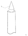
Fig. 1 bis Fig. 5 erläutert, die jeweils eine insbesondere bevorzugte Ausführungsform der Erfindung darstellen. In denFig. 1 bis Fig. 5 bedeuten 1 = Nietdorn oder Nietzapfen; 2 = spritzgegossenes (oder gepresstes) Thermoplastteil, z.B. eine Rippenstruktur; 3 = endlosfaserverstärktes Halbzeug; 4 = Presswerkzeug; 5 = Nietstempel; 6 = Führungs- und Isolationshülse; 7 = Heißluft; 8 = Infrarot Strahler; 9 = Ultraschall Nietstempel; 10 = Nietkopf. - Fig.1
- zeigt einen erfindungsgemäß einzusetzenden kegelförmigen Nietdorn bzw. Nietzapfen.
- Fig.2
- zeigt ein erfindungsgemäß einzusetzendes Thermoplastbauteil (2) mit drei Nietdornen (1) / bzw. Nietzapfen, angeordnet auf den Rippenkreuzen des Thermoplastbauteils.
- Fig.3
- zeigt die Verfahrensschritte des erfindungsgemäßen Verfahrens:
- a) das lokale Erwärmen eines durch Führungs- und Isolationshülsen (6) in einem Presswerkzeug (4) fixierten endlosfaserverstärkten Halbzeugs (3), bevorzugt einer Tepex® Platte, in einem Presswerkzeug (4) durch Heißluft, die durch den Kanal (7) eingeblasen wird, wobei (3) auf seiner Gegenseite durch wenigstens einen pyramidalen oder kegelförmigen Nietdorn bzw. Nietzapfen (1) als Bestandteil eines als Fügepartner dienenden Thermoplastteils (2) fixiert wird,
- b) das Durchdringen des in Schritt a) erwärmten endlosfaserverstärkten Halbzeugs (3) von wenigstens einem pyramidalen oder kegelförmigen Nietdorn bzw. Nietzapfen (1) als Bestandteil des als Fügepartner dienenden wenigstens einen Thermoplastteils (2), ohne dass zuvor das endlosfaserverstärkte Halbzeug (3) gebohrt oder gelocht wurde mit anschließender Erwärmung des wenigstens einen pyramidalen oder kegelförmigen Nietdorns bzw. Nietzapfens (1) mittels Heißluft (7) und
- c) das Umformen des wenigstens einen nach Schritt b) erhitzten und mit der Spitze aus dem durchbrochenen endlosfaserverstärkten Halbzeug (3) hinausragenden pyramidalen oder kegelförmigen Nietdorns bzw. Nietzapfens (1) durch einen Nietstempel (5) zu wenigstens einem Nietkopf (10) sowie Erstarren desselben oder derselben und Erhalt eines festen Stoffschlusses und Formschlusses von Thermoplastteil (2) und endlosfaserverstärktem Halbzeug (3).
- Fig. 4
- zeigt eine erfindungsgemäße Variante zu dem in
Fig.3 dargestellten und beschriebenen Verfahren, indem- a) ein endlosfaserverstärktes Halbzeug (3) in einem Presswerkzeug (4) mittels Infrarotstrahler (8) lokal erwärmt wird, wobei das endlosfaserverstärkte Halbzeug (3), bevorzugt eine Tepex® Platte, von der Unterseite her durch wenigstens einen pyramidalen oder kegelförmigen Nietdorn bzw.Nietzapfen (1) wenigstens eines Thermoplastteils (2) fixiert wird,
- b) das Durchdringen des in Schritt a) lokal erwärmten endlosfaserverstärkten Halbzeugs (3) von wenigstens einem pyramidalen oder kegelförmigen Nietdorn bzw. Nietzapfen (1) als Bestandteil des als Fügepartner dienenden wenigstens einen Thermoplastteils (2), ohne dass zuvor das endlosfaserverstärkte Halbzeug (3) gebohrt oder gelocht wurde und
- c) das Umformen des wenigstens einen pyramidalen oder kegelförmigen Nietdorns bzw. Nietzapfens (1) durch wenigstens einen Ultraschallnietstempel (9) zu wenigstens einem Nietkopf (10) unter Erhalt eines festen Formschlusses und Stoffschlusses von endlosfaserverstärktem Halbzeug (3) und wenigstens einem Thermoplastteil (2).
- Fig. 5
- zeigt zwei Nietdorne bzw. Nietzapfen nach der Durchdringung eines endlosfaserverstärkten Halbzeugs sowie einen Nietkopf (10), der nach Einwirken eines Nietstempels auf einen Nietdorn bzw. Nietzapfen nach dessen Durchdringung des endlosfaserverstärkten Halbzeugs ausgeformt wurde.
- In der Verbundtechnik wird zwischen einem formschlüssigen und einem stoffschlüssigen Verbund unterschieden. Während beim formschlüssigen Verbund der Zusammenhalt der Komponenten durch hinterschnittige Bereiche erzielt wird, müssen hierzu beim stoffschlüssigen Verbund, insbesondere beim Verbund von Kunststoff-Metall Komponenten, Haftvermittler, auch als Primer bezeichnet, eingesetzt werden.
- Ein fester Stoffschluss im Sinne der vorliegenden Erfindung bedeutet, dass endlosfaserverstärktes Halbzeug bzw. Organoblech und Spritzgießmasse des Thermoplastteils aus derselben Matrix bestehen, wodurch an den Verbindungsstellen beider Komponenten, während des Verbindungsvorgangs, ein stoffschlüssiger Verbund entsteht.
- Fester Formschluss im Sinne der vorliegenden Erfindung bedeutet, dass das erwärmte Polymer über Mikrostrukturen in der Oberfläche des Organoblech-Grundkörpers und über den Nietzapfen und dessen Durchdringung des Organoblech-Grundkörpers eine feste Verbindung mit diesem eingeht. Gemäß
EP-A 0 370 342 ist ein fester Formschluss sinngemäß das Gegenstück zu einem losen Formschluss und bedeutet einen Verbund von zwei Komponenten ohne Spiel. Der Begriff Formschluss selber bedeutet, dass der formschließende Querschnitt unter Last zerstört werden muss, um die verbundenen Teilstücke, hier endlosfaserverstärktes Halbzeug und Thermoplastteil, voneinander zu trennen. - Ein stoffschlüssiger Verbund und ein formschlüssiger Verbund werden am Beispiel von Kunststoff-Metall Erzeugnissen beispielsweise im Dokument "Hochschule_trifft_Mittelstand-IKV- Klaus_Kuesters - Highlight.pdf" von www.ikv-aachen.de vom 13. Juli 2011 gegenüber gestellt. Beim formschlüssigen Verbund ist die punktuelle Krafteinleitung charakteristisch, während der stoffschlüssige Verbund durch eine flächige Krafteinleitung gekennzeichnet ist. Im Gegensatz zum Kunststoff-Metall Verbund in der oben genannten Publikation, ist in der vorliegenden Erfindung aufgrund derselben Matrix im endlosfaserverstärkten Halbzeug sowie im Thermoplastteil kein Haftvermittler erforderlich, um zusätzlich zum formschlüssigen Verbund einen stoffschlüssigen Verbund zu erzielen.
- In bevorzugter Ausführungsform wird das endlosfaserverstärkte Halbzeug im Schritt a) lokal auf Temperaturen erwärmt, die abhängig vom Thermoplasten im Matrixkunststoff des Organoblechs im Bereich von 40°C unterhalb bis zu 5°C oberhalb des Schmelzpunktes des Thermoplasten im Organoblech liegen. Diese Temperaturen liegen für die im Rahmen der vorliegenden Erfindung bevorzugt für die Herstellung von Organoblechen genannten Thermoplasten im Bereich von 140° C bis 380° C, werden aber unter Umständen durch im Organoblech eingesetzte Additive maßgeblich beeinflusst. Für das in einer Ausführungsform insbesondere bevorzugt einzusetzende Polyamid 6 (PA6) liegt die Temperatur zum Erwärmen des Organoblechs im Bereich von 140° C bis 220° C, bevorzugt im Bereich von 180° C bis 220° C, besonders bevorzugt im Bereich von 200° C bis 220° C, ganz besonders bevorzugt im Bereich von 210° C bis 220° C, insbesondere bevorzugt im Bereich von 215° C bis 220° C.
- Die vorliegende Erfindung erbrachte zudem die überraschende Erkenntnis, dass ein formschlüssiger und stoffschlüssiger Verbund erzielt werden kann, selbst wenn das einzusetzende Organoblech in Schritt a) auf Temperaturen von bis zu 40°C unterhalb des Schmelzpunktes des in der Matrix des Organoblechs einzusetzenden Thermoplasten, insbesondere im Falle des PA6 als Matrix des Organoblechs, erwärmt wird.
- Ein erfindungsgemäß einzusetzendes endlosfaserverstärktes Halbzeug bzw. Organoblech umfasst wenigstens eine Lage eines Endlosfasertextils in einem Thermoplasten als Matrixkunststoff. Herstellungsbedingt handelt es sich dabei um ein zunächst ebenflächiges Erzeugnis, das erst durch ein Umformungsverfahren in ein dreidimensionales Erzeugnis überführt wird. In einer bevorzugten Ausführungsform enthält ein solches Organoblech wenigstens zwei Lagen eines Endlosfasertextils, jedoch höchstens 24 Lagen. Besonders bevorzugt enthält ein erfindungsgemäß einzusetzendes Organoblech wenigstens zwei bis fünf Lagen, ganz besonders bevorzugt enthält ein erfindungsgemäß einzusetzendes Organoblech zwei oder drei Lagen eines Endlosfasertextils.
- In einer bevorzugten Ausführungsform werden für das erfindungsgemäß einzusetzende Organoblech Endlosfasertextilien von Geweben oder Gelegen auf Basis wenigstens eines Rohstoffs der Gruppe Glas, Kohlenstoff, Aramid und Stahl oder deren Mischformen, eingesetzt.
- Bevorzugt werden Glasfasern, Kohlenstofffasern, Aramidfasern oder Stahlfasern im Organoblech eingesetzt, besonders bevorzugt Glasfasern oder Kohlenstofffasern, ganz besonders bevorzugt Glasfasern.
- Bevorzugt werden Lagen von Glasfasergewebe mit einem Gewicht im Bereich von 50 g/m2 bis 1200 g/m2, besonders bevorzugt im Bereich von 200 g/m2 bis 800 g/m2, ganz besonders bevorzugt im Bereich von 550 g/cm2 bis 650 g/cm2 eingesetzt.
- In einer bevorzugten Ausführungsform für die Matrix des erfindungsgemäß einzusetzenden endlosfaserverstärkten Halbzeugs/Organoblechs als Kunststoff wenigstens ein Thermoplast der Gruppe Polyamid 6 (PA6), Polyamid 66 (PA66), Polypropylen (PP), Polyphenylensulfid (PPS), Polyurethan (TPU), Polyphthalamid (PPA), Polybutylenterephthalat (PBT), Polyamid 12 (PA12) und Polycarbonat (PC) eingesetzt. Bevorzugt werden PA6, PA66 oder PP für die Matrix des Organoblechs eingesetzt, besonders bevorzugt PA6.
- Bevorzugt werden teilkristalline Kunststoffe eingesetzt, besonders bevorzugt teilkristalline Polyamide, insbesondere teilkristallines Polyamid 6. Gemäß
DE 10 2011 084 519 A1 besitzen teilkristalline Polyamide eine Schmelzenthalpie von mehr als 25 J/g, gemessen mit der DSC-Methode gemäß ISO 11357 beim zweiten Aufheizen und Integration des Schmelzpeaks. Sie unterscheiden sich dadurch von den semikristallinen Polyamiden, die eine Schmelzenthalpie im Bereich von 4 bis 25 J/g, gemessen mit der DSC-Methode gemäß ISO 11357 beim 2. Aufheizen und Integration des Schmelzpeaks und von den amorphen Polyamiden mit einer Schmelzenthalpie von weniger als 4 J/g, gemessen mit der DSC-Methode gemäß ISO 11357 beim 2. Aufheizen und Integration des Schmelzpeaks. - Die Kennzeichnung der Polyamide im Rahmen der vorliegenden Erfindung entspricht internationaler Norm, wobei die erste(n) Ziffer(n) die C-Atomzahl des Ausgangsdiamins und die letzte(n) Ziffer(n) die C-Atomzahl der Dicarbonsaure angeben. Wird nur eine Zahl genannt, so bedeutet dies, dass von einer α,ω -Aminocarbonsaure bzw. von dem davon abgeleiteten Lactam ausgegangen worden ist; im Übrigen sei verwiesen auf H. Domininghaus, Die Kunststoffe und ihre Eigenschaften, Seiten 272 ff. , VDI-Verlag, 1976).
- Bevorzugt wird für das erfindungsgemäß einzusetzende Organoblech ein Thermoplast eingesetzt, der eine Schmelzviskosität im Bereich von 101 bis 106 Pa·s hat. Besonders bevorzugt werden für die Matrix des Organoblechs Polyamide mit einer relativen Viskosität ηrel, gemessen in 1 gew.-%iger m-Kresollösung bei 25° C im Bereich von 2,3 bis 4,0; besonders bevorzugt im Bereich von 2,7 bis 3,5 eingesetzt. Unter der Schmelzviskosität wird erfindungsgemäß die Viskosität in der schmelzflüssigen Phase am Schmelzpunkt des / der im Rahmen der vorliegenden Erfindung einzusetzenden Kunststoffe(s), bevorzugt Thermoplasten, verstanden. Im erweiterten Sinne versteht man insbesondere bei makromolekularen Stoffen, die meist keinen festen Schmelzpunkt besitzen, auch Viskositätsfunktionen, die an der Schmelze bei anderen Temperaturen als der Schmelztemperatur gemessen wurden. Diese Bedeutung ist insbesondere für Polymere wichtig, da diese im Gegensatz zu niedermolekularen Stoffen meist nicht über einen festen Schmelzpunkt, sondern über einen weiten Schmelz- bzw. Erweichungsbereich verfügen. Die Schmelzviskosität ist nicht nur vom Molekülaufbau (Molmasse, Verzweigungsgrad, Wechselwirkungen), sondern in erheblichem Maße auch von der Temperatur und den Scherbedingungen (z.B. Schergefälle oder Düsengeometrie) abhängig. Demzufolge wird die Schmelzviskosität eines Stoffes meist für jeweils verschiedene Temperaturen in Abhängigkeit von der Schergeschwindigkeit (oder vergleichbaren Größen) gemessen und die Abhängigkeiten dann graphisch dargestellt. Die Viskosität von Schmelzen homologer Reihen makromolekularer Substanzen nimmt mit konstanter Temperatur mit steigendem Gewichtsmittel des Molekulargewichtes zu. Die Schmelzviskosität wird meist in heizbaren Rotations-Viskosimetern vom Platte-Kegel- oder Platte-Platte-Typ oder in speziellen Kapillar-Viskosimetern ermittelt, wobei auf Temperaturkonstanz während der Messung zu achten ist. Die Schmelzviskosität hat insbesondere für die Auslegung und die Fahrweise von Kunststoffverarbeitungsanlagen eine große praktische Bedeutung. Wichtig ist die Kenntnis der Schmelzviskositäten bei allen formgebenden Verfahren, die Schmelzen nutzen, insbesondere Schmelzspinnen, Extrudieren, Spritzgießen und Thermoformen. Die Schmelzviskosität wurde im Rahmen der vorliegenden Erfindung gemäß ISO 11443 bestimmt (siehe auch H.Steffens, F. Sauerwald, Kolloid Zeitschrift, Vol. 148, Ausg. 3, September 1956, 144 - 150)
- Erfindungsgemäß insbesondere bevorzugt als Matrix des Organoblechs einzusetzendes teilkristallines PA66 (CAS No. 32131-17-2) ist beispielsweise unter der Bezeichnung Durethan® A bei der Lanxess Deutschland GmbH, Köln, Deutschland erhältlich. Erfindungsgemäß insbesondere bevorzugt als Matrix des Organoblechs einzusetzendes teilkristallines PA6 (CAS No. 25038-54-4) ist beispielsweise unter der Bezeichnung Durethan® B bei der Lanxess Deutschland GmbH, Köln, Deutschland erhältlich.
- Bevorzugt liegt der Fasergehalt im erfindungsgemäß einzusetzenden Organoblech im Bereich von 40 bis 60 Vol.-%, besonders bevorzugt im Bereich von 45 bis 55 Vol.-%, ganz besonders bevorzugt im Bereich von 45 bis 48 Vol.%, wobei die Summe aller Inhaltsstoffe des Organoblechs stets 100 Vol.-% ergibt. Als weitere gegebenenfalls im erfindungsgemäß einzusetzenden Organoblech vorliegende Inhaltsstoffe werden üblicherweise die im jeweiligen Kunststoff einzusetzenden Additive eingesetzt, die dem Fachmann bekannt sind.
- Erfindungsgemäß als endlosfaserverstärkte Halbzeuge einzusetzende Organobleche sind beispielsweise bei der Firma Bond-Laminates GmbH, Brilon, Deutschland unter der Marke TEPEX® erhältlich. Diese Organobleche sind vollständig imprägnierte und konsolidierte Halbzeuge. Versuche im Rahmen der vorliegenden Erfindung wurden mit "TEPEX® dynalite 102-RG600(2)/47% Typ B 1 mm black" durchgeführt, einem 1 mm Materialstärke aufweisenden, schwarz eingefärbten Organoblech aus zwei Lagen Rovingglas-Gewebe, mit einem Gewicht von 600 g/m2 und einem in Bezug auf die Polyamid 6 Matrix Faservolumengehalt von 47%.
- Ein Herstellungsverfahren für erfindungsgemäß einzusetzende Organobleche ist beispielsweise aus
EP 1 923 420 A1 bekannt, deren Inhalt hiermit vollumfänglich umfasst wird. Die bei der Herstellung von Organoblechen angewandten Temperaturen orientieren sich an den Erweichungspunkten der einzusetzenden Kunststoffe, bevorzugt Thermoplasten, und liegen bevorzugt im Bereich von 140 bis 380° C. Die bei der Herstellung von Organoblechen anzuwendenden Flächendrücke liegen bevorzugt im Bereich von 0,1 bis 5 MPa. - Bei dem als Fügepartner einzusetzenden wenigstens einen Thermoplastteil handelt es sich bevorzugt um spritzgegossene Thermoplastbauteile auf Basis wenigstens eines Thermoplasten der Reihe Polyamid 6 (PA6), Polyamid 66 (PA66), Polyprolylen (PP), Polyphenylensulfid (PPS), thermoplastisches Polyurethan (TPU), Polyphthalamid (PPA), Polybutylenterephthalat (PBT), Polyamid 12 (PA12) oder Polycarbonat (PC). Bevorzugt werden PA6, PA66 oder PP als Thermoplast für die Matrix des Thermoplastteils eingesetzt, besonders bevorzugt PA6.
- In bevorzugter Ausführungsform handelt es sich um verstärkte Thermoplastteile, die wenigstens einen Verstärkungsstoff der Reihe Glas, Kohlenstoff, Aramid oder Stahl oder deren Mischformen, aufweisen.
- Bevorzugt werden Glasfasern, Kohlenstofffasern, Aramidfasern oder Stahlfasern im Organoblech eingesetzt, besonders bevorzugt Glasfasern oder Kohlenstofffasern, ganz besonders bevorzugt Glasfasern.
- Die insbesondere bevorzugt einzusetzenden Glasfasern haben bevorzugt einen Faserdurchmesser im Bereich von 7 und 18 µm, besonders bevorzugt im Bereich von 9 und 15 µm, und werden als Endlosfasern oder als geschnittene oder gemahlene Glasfasern zugesetzt. Die Fasern werden bevorzugt mit einem geeigneten Schlichtesystem und einem Haftvermittler bzw. Haftvermittlersystem, besonders bevorzugt auf Silanbasis, ausgerüstet.
- Ganz besonders bevorzugte Haftvermittler auf Silanbasis für die Vorbehandlung sind Silanverbindungen der allgemeinen Formel (I)
(X-(CH2)q)k-Si-(O-CrH2r+1)4-k (I)
in der die Substituenten folgende Bedeutung haben: - X:
- NH2-, HO-,

- q:
- eine ganze Zahl von 2 bis 10, bevorzugt 3 bis 4,
- r:
- eine ganze Zahl von 1 bis 5, bevorzugt 1 bis 2,
- k:
- eine ganze Zahl von 1 bis 3, bevorzugt 1.
- Insbesondere bevorzugte Haftvermittler sind Silanverbindungen aus der Gruppe Aminopro-pyltrimethoxysilan, Aminobutyltrimethoxysilan, Aminopropyltriethoxysilan, Aminobutyl-triethoxysilan sowie die entsprechenden Silane, welche als Substituent X eine Glycidylgruppe enthalten.
- Für die Ausrüstung der Glasfasern werden die Silanverbindungen bevorzugt in Mengen von 0,05 bis 2 Gew.-%, besonders bevorzugt 0,25 bis 1,5 Gew.-% und insbesondere 0,5 bis 1 Gew.-% bezogen auf die Glasfasern zur Oberflächenbeschichtung eingesetzt.
- Die Glasfasern können bedingt durch die Verarbeitung zur Formmasse bzw. dem daraus herzustellenden Erzeugnis in der Formmasse bzw. im Erzeugnis einen kleineren d97- bzw. d50-Wert aufweisen, als die ursprünglich eingesetzten Glasfasern. Die Glasfasern können bedingt durch die Verarbeitung zur Formmasse bzw. Formkörper in der Formmasse bzw. im Formkörper kürzere Längenverteilungen als ursprünglich eingesetzt aufweisen.
- Der Gehalt an Verstärkungsstoff im Thermoplasten des als Fügepartner einzusetzenden Thermoplastteils liegt bevorzugt im Bereich von 15 bis 60 Vol.-%, besonders bevorzugt im Bereich von 30 bis 60 Vol.-%, ganz besonders bevorzugt im Bereich von 50 bis 60 Vol.-% bezogen auf das Gesamtgewichts des Thermoplastteils, wobei die Summe aller Volumenprozente der Inhaltsstoffe des Thermoplastteils stets 100 ergibt.
- Neben dem Verstärkungsstoff bzw. der Endlosfaserverstärkung können weitere Additive sowohl im Thermoplasten des als Fügepartner dienenden Thermoplastteils, als auch im Organoblech vorhanden sein. Übliche Additive sind bevorzugt Stabilisatoren, Entformungsmittel, UV-Stabilisatoren, Gammastrahlenstabilisatoren, Antistatika, Fließhilfsmittel, Flammschutzmittel, Elastomermodifikatoren, Brandschutzadditive, Emulgatoren, Nukleierungsmittel, Weichmacher, Gleitmittel, Farbstoffe oder Pigmente. Die genannten und weitere geeignete Additive sind zum Beispiel beschrieben in Gächter, Müller, Kunststoff-Additive, 3. Ausgabe, Hanser-Verlag, München, Wien, 1989 und im Plastics Additives Handbook, 5th Edition, Hanser-Verlag, München, 2001. Die Additive können alleine oder in Mischung bzw. in Form von Masterbatchen eingesetzt werden.
- In einer bevorzugten Ausführungsform enthält die Matrix des Organoblechs denselben Thermoplasten wie er in dem wenigstens einen Thermoplasteil enthalten ist, aus der Gruppe Polyamid 6 (PA6), Polyamid 66 (PA66), Polyprolylen (PP), Polyphenylensulfid (PPS), thermoplastisches Polyurethan (TPU), Polyphthalamid (PPA), Polybutylenterephthalat (PBT), Polyamid 12 (PA12) und Polycarbonat (PC). Bevorzugt werden sowohl in der Matrix des Organoblechs als im wenigstens einen Thermoplastteil dieselben Thermoplasten ausgewählt aus der Gruppe PA6, PA66 und PP eingesetzt, besonders bevorzugt PA6.
- Das Verfahren des Spritzgusses zur Herstellung der als Fügepartner dienenden Thermoplastteile ist dem Fachmann bekannt. Der Spritzguss thermoplastischer Formmassen zeichnet sich dadurch aus, dass der Rohstoff, bevorzugt in Granulatform, in einem beheizten zylindrischen Hohlraum aufgeschmolzen (plastifiziert) und als Spritzmasse unter Druck in einen temperierten Hohlraum gespritzt wird. Nach dem Abkühlen (Erstarren) der Masse wird das Spritzgussteil entformt. Beim Spritzgussverfahren unterscheidet man die Verfahrensschritte 1. Plastifizieren / Aufschmelzen, 2. Einspritzphase (Füllvorgang),3. Nachdruckphase (wegen thermischer Kontraktion bei der Kristallisation) und 4. Entformen. Eine Spritzgießmaschine besteht aus einer Schließeinheit, der Spritzeinheit, dem Antrieb und der Steuerung. Zur Schließeinheit gehören feste und bewegliche Aufspannplatten für das Werkzeug, eine Stirnplatte sowie Säulen und Antrieb der beweglichen Werkzeugaufspannplatte (Kniehebelgelenk oder hydraulische Schließeinheit). Eine Spritzeinheit umfasst den elektrisch beheizbaren Zylinder, den Antrieb der Schnecke (Motor, Getriebe) und die Hydraulik zum Verschieben der Schnecke und Spritzeinheit. Die Aufgabe der Spritzeinheit besteht darin, das Polymer enthaltende Pulver bzw. das Polymer enthaltende Granulat aufzuschmelzen, zu dosieren, einzuspritzen und nachzudrücken (wegen Kontraktion). Das Problem des Rückflusses der Schmelze innerhalb der Schnecke (Leckströmung) wird durch Rückstromsperren gelöst. Im Spritzgießwerkzeug wird dann die einströmende Schmelze gelöst, gekühlt und somit das zu fertigende Erzeugnis gefertigt. Notwendig dazu sind immer zwei Werkzeughälften. Beim Spritzguss unterscheidet man folgende Funktionskomplexe: i) Angusssystem, ii) Formbildende Einsätze, iii) Entlüftung, iv) Maschinen- und Kraftaufnahme, v) Entformungssystem und Bewegungsübertragung sowie vi) Temperierung.
- Erfindungsgemäß werden Thermoplastteile eingesetzt, die wenigstens einen Nietdorn oder Nietzapfen aufweisen. Dieser bzw. diese werden durch entsprechende Kavitäten im Spritzgießwerkzeug bzw. im Presswerkzeug im Spritzgießprozess bzw. Pressprozess direkt an das Thermoplastteil mit angeformt. Demzufolge besteht der wenigstens eine Nietdorn bzw. Nietzapfen bevorzugt aus demselben Thermoplasten, wie das erfindungsgemäß für den Verbund einzusetzende Thermoplastteil.
- Ist das erfindungsgemäß wenigstens eine einzusetzende Thermoplastteil ein Erzeugnis mit Verstärkungsrippen, so befindet sich der wenigstens eine Nietdorn bzw. Nietzapfen bevorzugt auf wenigstens einem Rippenkreuz, wobei der wenigstens eine Nietdorn aus der Ebene wenigstens eines Rippenkreuzes herausragt, damit er für die Durchdringung des mit dem Thermoplastteil zu verbindenden Organoblechs zur Verfügung steht. Beispiele für Erzeugnisse mit Verstärkungsrippen werden in
EP 0 370 342 A2 offenbart. - Sollte am Thermoplastteil kein Rippenkreuz oder keine ausreichende Anzahl an Rippenkreuzen für Nietdorne vorhanden sein, so kann in bevorzugter Ausführungsform der wenigstens eine Nietdorn auf Bauteilecken oder auf der mittleren Position von Thermoplast-Verstärkungsrippen angeordnet sein..
- Der erfindungsgemäße Verbund ist in den Bereichen Schiffsbau, Flugzeugbau, Automotive und Non-Automotive, bevorzugt in Fahrzeugteilen (automotive Bereich), in tragenden Teilen von Büromaschinen, Haushaltsmaschinen oder anderen Maschinen, in Konstruktionselementen für Dekorationszwecke, Treppenstufen, Fahrtreppenstufen oder Kanaldeckeln einsetzbar. Die vorliegende Erfindung betrifft daher die Verwendung dieses Verbunds in den genannten Bereichen.
- Bevorzugt erfolgt der Einsatz im Automotive Bereich in Kraftfahrzeugen als Dachstrukturen, bestehend beispielsweise aus Dachrahmen, Dachspriegel und/oder Dachspitzen, für Säulenstrukturen, insbesondere A-, B- und/oder C-Säulen von Kraftfahrzeugen, für Fahrwerk-Strukturen, bestehend beispielsweise aus Achsschenkel, Koppelstange, Querlenker und/oder Stabilisatoren, für Längsträgerstrukturen, beispielsweise bestehend aus Längsträger und/oder Schweller, für Vorderwagenstrukturen, bestehend beispielsweise aus Frontends, Vorderwagenmodul, Scheinwerferrahmen, Schlossträger, Querträger, Kühlerträger und/oder Montageträger, für Pedalstrukturen, beispielsweise bestehend aus Brems-, Gasund Kupplungspedal, Pedalbock und/oder Pedalmodul, für Türen- und Klappenstrukturen, beispielsweise vordere und hintere Fahrer- und Beifahrertüren, Heckklappen und/oder Motorhaube, für Instrumententafelträgerstrukturen, bestehend beispielsweise aus Querträger, Instrumententafelträger und/oder Cockpitträger, für Ölwannen, beispielsweise Getriebeölwannen und/oder Ölmodule, für Sitzstrukturen, beispielsweise bestehend aus Sitzlehnenstruktur, Rückenlehnenstruktur, Sitzwannenstruktur, Gurtholm und/oder Armlehnen, komplette Frontends, Fußgängerschutz Beam, reine Schlossbrücken für Motorhauben oder Kofferraumdeckel, Dachspriegel vorne, Dachspriegel hinten, Dachrahmen, Dachmodule (gesamtes Dach), Schiebedach-Trägerteile, Armaturentafelträgerteile (Cross Car Beam), Lenkstockhalter, Feuerwand, Pedale, Pedalblöcke, Schaltblöcke von Getrieben, A-, B-, C-Säulen, B-Säulenmodule, Längsträger, Knotenelemente zum Verbinden von Längsträgern und B-Säulen, Knotenelemente zum Verbinden von A-Säule und Querträger, Knotenelemente zum Verbinden von A-Säule, Querträger und Längsträger, Querträger, Kotflügelbänke, Kotflügelmodule, Crash Boxen, Rear Ends, Reserveradmulden, Motorhauben, Motorabdeckungen, Wasserkastenbank, Motorversteifungen (Versteifung Vorderwagen), Fahrzeugboden, Sitzversteifung, Bodenversteifungen, Heckklappen, Fahrzeugrahmen, Sitzstrukturen, Rückenlehnen, Sitzschalen, Rücksitzlehnen mit und ohne Gurtintegration, Hutablagen, Sitzquerträger, Ventildeckel, Lagerschilde für Lichtmaschinen oder Elektromotoren, komplette Fahrzeugtürstrukturen, Seitenaufprallträger, Modulträger, Ölwannen, Getriebeölwannen, Ölmodule, Scheinwerferrahmen, Schweller, Schwellerverstärkungen, Fahrwerkskomponenten sowie Motorrollerrahmen.
- Bevorzugter Einsatz eines erfindungsgemäßen Verbunds im non automotive Bereich, ist in E/E Geräten, Haushaltsgeräten, Möbeln, Heizthermen, Einkaufswagen, Regale, Treppenstufen, Fahrtreppenstufen, Kanaldeckeln (E/E Geräte = elektrische und elektronische Geräte).
- Selbstverständlich eignet sich der erfindungsgemäße Verbund von Organoblech mit Thermoplastteilen auch zum Einsatz in Bahnfahrzeugen, Flugzeugen, Schiffen, Schlitten, Motorrollern oder sonstigen Fortbewegungsmitteln, wo es auf leichte jedoch stabile Konstruktionen ankommt.
- Thermoplastisches Halbzeug/Organoblech:TEPEX® dynalite 102-RG600(2)/47% Typ B 1 mm black
Nietdorn / Thermoplastteil: Durethan® BKV 30, Durethan® AKV 30 - Vorrichtung zum Durchdrücken eines Dorns durch eine Platte bestehend aus einer Standbohrmaschine.
- Untersucht wurde, ob sich ein Organoblech aus dem o.g. Tepex® Material mit einem kurzglasfaserverstärkten Nietdorn, hier im speziellen aus PA6 und PA66 gefertigt, durchdringen bzw. durchstoßen lässt, ohne vorher eine Öffnung im Organoblech vorgesehen zu haben.
- Folgende Parameter wurden in der Versuchsreihe variiert:
Temperatur des Organoblechs 140 °C, 180 °C, 220 °C sowie Zwischenschritte im relevanten Bereich Material des Nietdorns Durethan® BKV30 oder Durethan® AKV30 - Die Organobleche wurden auf eine Abmessung von ca. 150 x 100 mm2 zugeschnitten und entsprechend des Versuchsplans im Ofen aufgeheizt:
- ■ 2x140°C
- ■ 2x180°C
- ■ 2 x 220 ° C
- Nietdorne wurden aus Angussdomen aus Durethan® AKV30 und Durethan® BKV 30 gedreht.
- Ein Nietdorn wurde in eine Standbohrmaschine eingespannt. Das aufgeheizte Organoblech wurde unter dem Nietdorn positioniert. Der Nietdorn wurde abgesenkt und durchdrang ggf. das Organoblech (CS = Composite Sheet).
- Die Versuche wurden ausgewertet. Dabei wurde auf das Verhalten des Nietdorns und des Organoblechs beim Durchstoßen geachtet. Die Ergebnisse sind in Tabelle 1 festgehalten.
Tabelle 1: Ergebnisse der Durchstoßversuche Versuchs- Nr. Temperatur [°C] BKV30 AKV30 1 140 CS lässt sich nicht durchstoßen 2 180 CS lässt sich durchstoßen Glasfasern werden teilweise durchtrennt 3 220 CS loftetCS lässt sich problemlos durchstoßen Glasfasern werden nicht durchtrennt nur zur Seite geschoben 4 200 CS lässt sich problemlos durchstoßen Glasfasern werden teilweise durchtrennt 5 210 CS lässt sich problemlos durchstoßen Glasfasern werden teilweise durchtrennt 6 215 CS schmilzt an der Oberfläche leicht an CS lässt sich problemlos durchstoßen Glasfasern werden nicht durchtrennt nur zur Seite geschoben - Ein Organoblech ließ sich mit einem verstärkten Kunststoff-Nietdorn durchstoßen, ohne dass die endlosen Verstärkungsfasern im Composite Sheet durchtrennt werden.
- Ab einer Vorheiztemperatur von 215° C war ein Anschmelzen der Oberfläche des Organoblechs zu erkennen.
- Bei einer Vorheiztemperatur von 220° C war die Matrix des Organoblechs soweit aufgeschmolzen, dass dieses loftete. Loften im Sinne der vorliegenden Erfindung bedeutet, dass das konsolidierte Organoblech, also das vollständig durch die thermoplastische Matrix imprägnierte Gewebe ohne jegliche Lufteinschlüsse, beim Erwärmen oberhalb der Schmelzetemperatur der thermoplastischen Matrix wieder aufquoll und Luft in den Faser/Matrix Verbund eindrang.
- Überraschenderweise ließ sich das Organoblech ab einer Vorheiztemperatur von 180° C (ca. 40° C unterhalb der Schmelzetemperautur) bereits durchstoßen.
- Ab einer Vorheiztemperatur von 215° C wurden die endlosen Glasfasern des Organoblechs vom Nietdorn verdrängt, jedoch nicht durchtrennt.
Claims (16)
- Verfahren zur Verbindung wenigstens eines endlosfaserverstärkten Halbzeugs mit wenigstens einem Thermoplastteil, dadurch gekennzeichnet, dass mana) wenigstens ein endlosfaserverstärktes Halbzeug in einem Presswerkzeug lokal dort erwärmt, wo der Verbund von endlosfaserverstärktem Halbzeug mit wenigstens einem Thermoplastteil erfolgen soll,b) wenigstens einen zunächst pyramidalen oder kegelförmigen Nietdorn oder Nietzapfen als Bestandteil des wenigstens einen Thermoplastteils durch das wenigstens eine lokal erhitzte zuvor weder gelochte noch durchbohrte endlosfaserverstärkte Halbzeug hindurch dringen lässt unter Beibehaltung der ursprünglichen Geometrie des /der Nietdorns(e) bzw. Nietzapfen(s) undc) den wenigstens einen durch das wenigstens eine endlosfaserverstärkte Halbzeug nach Schritt b) hinausragenden Nietdorn bzw. Nietzapfen durch wenigstens einen Nietstempel zu einem Nietkopf bzw. Nietköpfen umformt und erstarren lässt, wobei es sich bei dem endlosfaserverstärkten Halbzeug um wenigstens eine Lage eines Endlosfasertextils in einem Thermoplasten als Matrixkunststoff handelt.
- Verfahren gemäß Anspruch 1, dadurch gekennzeichnet, dass vor Verfahrensschritt c) der wenigstens eine durch das wenigstens eine endlosfaserverstärkte Halbzeug hinausragende Nietdorn bzw. Nietzapfen vor der Umformung erwärmt wird.
- Verfahren gemäß Anspruch 2, dadurch gekennzeichnet, dass die Erwärmung des wenigstens einen Nietdorns durch Heißluft oder durch Ultraschallschwingungen erfolgt.
- Verfahren gemäß einem der Ansprüche 1 bis 3, dadurch gekennzeichnet, dass es sich bei dem Thermoplastteil um ein spritzgegossenes oder gepresstes Thermoplastteil, bevorzugt um ein spritzgegossenes Thermoplastteil handelt.
- Verfahren gemäß einem der Ansprüche 1 bis 4, dadurch gekennzeichnet, dass das endlosfaserverstärkte Halbzeug im Schritt a) lokal auf Temperaturen erwärmt wird, die abhängig vom Thermoplasten im Matrixkunststoff des Organoblechs im Bereich von 40°C unterhalb bis zu 5°C oberhalb des Schmelzpunktes des Thermoplasten im Organoblech liegen.
- Verfahren gemäß Anspruch 5, dadurch gekennzeichnet, dass diese Temperaturen im Bereich von 140° C bis 380° C liegen.
- Verfahren gemäß einem der Ansprüche 1 bis 6, dadurch gekennzeichnet, dass als Kunststoff für die Matrix des endlosfaserverstärkten Halbzeugs wenigstens ein Thermoplast der Gruppe Polyamid 6 (PA6), Polyamid 66 (PA66), Polypropylen (PP), Polyphenylensulfid (PPS), Polyurethan (TPU), Polyphthalamid (PPA), Polybutylenterephthalat (PBT), Polyamid 12 (PA12) und Polycarbonat (PC) eingesetzt wird, bevorzugt PA6, PA66 oder PP, besonders bevorzugt PA6.
- Verfahren gemäß Anspruch 7, dadurch gekennzeichnet, dass die Temperatur zum Erwärmen des endlosfaserverstärkten Halbzeugs im Bereich von 140° C bis 220° C liegt.
- Verfahren gemäß einem der Ansprüche 1 bis 8, dadurch gekennzeichnet, dass es sich bei dem wenigstens einen Thermoplastteil um spritzgegossene Thermoplastbauteile auf Basis wenigstens eines Thermoplasten der Reihe Polyamid 6 (PA6), Polyamid 66 (PA66), Polypropylen (PP), Polyphenylensulfid (PPS), thermoplastisches Polyurethan (TPU), Polyphthalamid (PPA), Polybutylenterephthalat (PBT), Polyamid 12 (PA12) oder Polycarbonat (PC) handelt, bevorzugt PA6, PA66 oder PP, besonders bevorzugt PA6.
- Verfahren gemäß einem der Ansprüche 1 bis 9, dadurch gekennzeichnet, dass die Matrix des endlosfaserverstärkten Halbzeugs sowie der wenigstens eine Thermoplastteil denselben Thermoplast aus der Gruppe Polyamid 6 (PA6), Polyamid 66 (PA66), Polyprolylen (PP), Polyphenylensulfid (PPS), thermoplastisches Polyurethan (TPU), Polyphthalamid (PPA), Polybutylenterephthalat (PBT), Polyamid 12 (PA12) und Polycarbonat (PC) enthalten, bevorzugt aus der Gruppe PA6, PA66 und PP, besonders bevorzugt PA6.
- Verfahren gemäß einem der Ansprüche 1 bis 10, dadurch gekennzeichnet, dass der wenigstens eine Nietdorn durch entsprechende Kavitäten im Spritzgießwerkzeug bzw. im Presswerkzeug im Spritzgießprozess bzw. Pressprozess direkt an das Thermoplastteil mit angeformt wurde und aus demselben Thermoplasten wie das für den Verbund einzusetzende Thermoplastteil besteht.
- Verfahren gemäß einem der Ansprüche 1 bis 11, dadurch gekennzeichnet, dass das wenigstens eine einzusetzende Thermoplastteil ein Erzeugnis mit Verstärkungsrippen, ist und sich der wenigstens eine Nietdorn auf wenigstens einem Rippenkreuz befindet, wobei der Dorn aus der Ebene des Rippenkreuzes herausragt.
- Verfahren gemäß einem der Ansprüche 1 bis 12, dadurch gekennzeichnet, dass der wenigstens eine Nietdorn aus demselben Thermoplasten, wie das für den Verbund einzusetzende Thermoplastteil besteht.
- Verfahren gemäß Anspruch 12 oder 13, dadurch gekennzeichnet, dass wenn am Thermoplastteil kein Rippenkreuz oder keine ausreichende Anzahl an Rippenkreuzen für Nietdorne vorhanden sind, der wenigstens eine Nietdorn auf Bauteilecken oder auf der mittleren Position von Thermoplast-Vertärkungsrippen angeordnet sein kann.
- Verbund von endlosfaserverstärkten Halbzeugen mit wenigstens einem Thermoplastteil, erhältlich durch ein Verfahren gemäß einem der Ansprüche 1 bis 14.
- Verwendung eines Verbunds gemäß Anspruch 15 in den Bereichen Schiffsbau, Flugzeugbau, Automotive und Non-Automotive, bevorzugt in Fahrzeugteilen (Automotive Bereich), in tragenden Teilen von Büromaschinen, Haushaltsmaschinen oder anderen Maschinen, in Konstruktionselementen für Dekorationszwecke, Treppenstufen, Fahrtreppenstufen oder Kanaldeckeln.
Priority Applications (1)
| Application Number | Priority Date | Filing Date | Title |
|---|---|---|---|
| EP13198709.1A EP2886305B1 (de) | 2013-12-20 | 2013-12-20 | Verbindungsverfahren |
Applications Claiming Priority (1)
| Application Number | Priority Date | Filing Date | Title |
|---|---|---|---|
| EP13198709.1A EP2886305B1 (de) | 2013-12-20 | 2013-12-20 | Verbindungsverfahren |
Publications (2)
| Publication Number | Publication Date |
|---|---|
| EP2886305A1 true EP2886305A1 (de) | 2015-06-24 |
| EP2886305B1 EP2886305B1 (de) | 2018-05-30 |
Family
ID=49918433
Family Applications (1)
| Application Number | Title | Priority Date | Filing Date |
|---|---|---|---|
| EP13198709.1A Active EP2886305B1 (de) | 2013-12-20 | 2013-12-20 | Verbindungsverfahren |
Country Status (1)
| Country | Link |
|---|---|
| EP (1) | EP2886305B1 (de) |
Cited By (7)
| Publication number | Priority date | Publication date | Assignee | Title |
|---|---|---|---|---|
| WO2017207611A1 (de) | 2016-06-03 | 2017-12-07 | Covestro Deutschland Ag | Mehrschichtverbundwerkstoff enthaltend spezielle copolycarbonate als matrixmaterial |
| WO2018007335A1 (de) | 2016-07-04 | 2018-01-11 | Covestro Deutschland Ag | Mehrschichtverbundwerkstoff enthaltend spezielle polycarbonat-zusammensetzungen als matrixmaterial |
| WO2019016374A1 (de) * | 2017-07-21 | 2019-01-24 | Lanxess Deutschland Gmbh | Türmodul |
| EP3502171A1 (de) | 2017-12-21 | 2019-06-26 | Covestro Deutschland AG | Mehrschichtverbundwerkstoff enthaltend spezielle polycarbonat-zusammensetzungen als matrixmaterial |
| EP3502170A1 (de) | 2017-12-19 | 2019-06-26 | Covestro Deutschland AG | Mehrschichtverbundwerkstoff enthaltend spezielle polycarbonat-zusammensetzungen als matrixmaterial |
| EP3502173A1 (de) | 2017-12-19 | 2019-06-26 | Covestro Deutschland AG | Design-mehrschichtverbundwerkstoff mit speziellen polycarbonat-zusammensetzungen als matrixmaterial |
| US11993061B2 (en) | 2016-07-04 | 2024-05-28 | Covestro Deutschland Ag | Multilayer composite material containing special polycarbonate compositions as a matrix material |
Citations (10)
| Publication number | Priority date | Publication date | Assignee | Title |
|---|---|---|---|---|
| EP0340094A2 (de) | 1988-04-27 | 1989-11-02 | Automobiles Peugeot | Verfahren zum Verbinden von einem ersten Gegenstand aus Kunststoff und einem zweiten Gegenstand durch Nieten. |
| EP0370342A2 (de) | 1988-11-25 | 1990-05-30 | Bayer Ag | Leichtbauteil |
| EP0392568A1 (de) * | 1986-11-21 | 1990-10-17 | Phillips Petroleum Company | Befestigungselemente aus thermoplastischem Verbundstoff |
| EP0823320A1 (de) * | 1996-02-27 | 1998-02-11 | Sumitomo Chemical Company Limited | Methode zur herstellung von kompositen |
| DE102004038084A1 (de) * | 2004-07-28 | 2006-03-23 | Technische Universität Dresden | Verfahren und Anordnung zur Herstellung genieteter Verbindungen zwischen flächigen Strukturen aus verstärkten Thermoplasten |
| EP1661689A2 (de) | 2004-11-25 | 2006-05-31 | Maschinenfabrik Spaichingen GmbH | Verfahren und Vorrichtung zum Verbinden von Gegenständen mittels wenigstens eines plastifizierbaren Verbindungselements |
| EP1923420A1 (de) | 2006-11-14 | 2008-05-21 | Bond Laminates Gmbh | Faserverbund-Werkstoff und Verfahren zu dessen Herstellung |
| DE102007055856A1 (de) | 2007-12-18 | 2009-06-25 | Faurecia Innenraum Systeme Gmbh | Nietschweißverfahren |
| EP2570685A1 (de) | 2011-09-14 | 2013-03-20 | Profil Verbindungstechnik GmbH & Co. KG | Nietelement |
| DE102011084519A1 (de) | 2011-10-14 | 2013-04-18 | Evonik Industries Ag | Verwendung einer Mehrschichtfolie für die Herstellung photovoltaischer Module |
-
2013
- 2013-12-20 EP EP13198709.1A patent/EP2886305B1/de active Active
Patent Citations (10)
| Publication number | Priority date | Publication date | Assignee | Title |
|---|---|---|---|---|
| EP0392568A1 (de) * | 1986-11-21 | 1990-10-17 | Phillips Petroleum Company | Befestigungselemente aus thermoplastischem Verbundstoff |
| EP0340094A2 (de) | 1988-04-27 | 1989-11-02 | Automobiles Peugeot | Verfahren zum Verbinden von einem ersten Gegenstand aus Kunststoff und einem zweiten Gegenstand durch Nieten. |
| EP0370342A2 (de) | 1988-11-25 | 1990-05-30 | Bayer Ag | Leichtbauteil |
| EP0823320A1 (de) * | 1996-02-27 | 1998-02-11 | Sumitomo Chemical Company Limited | Methode zur herstellung von kompositen |
| DE102004038084A1 (de) * | 2004-07-28 | 2006-03-23 | Technische Universität Dresden | Verfahren und Anordnung zur Herstellung genieteter Verbindungen zwischen flächigen Strukturen aus verstärkten Thermoplasten |
| EP1661689A2 (de) | 2004-11-25 | 2006-05-31 | Maschinenfabrik Spaichingen GmbH | Verfahren und Vorrichtung zum Verbinden von Gegenständen mittels wenigstens eines plastifizierbaren Verbindungselements |
| EP1923420A1 (de) | 2006-11-14 | 2008-05-21 | Bond Laminates Gmbh | Faserverbund-Werkstoff und Verfahren zu dessen Herstellung |
| DE102007055856A1 (de) | 2007-12-18 | 2009-06-25 | Faurecia Innenraum Systeme Gmbh | Nietschweißverfahren |
| EP2570685A1 (de) | 2011-09-14 | 2013-03-20 | Profil Verbindungstechnik GmbH & Co. KG | Nietelement |
| DE102011084519A1 (de) | 2011-10-14 | 2013-04-18 | Evonik Industries Ag | Verwendung einer Mehrschichtfolie für die Herstellung photovoltaischer Module |
Non-Patent Citations (6)
| Title |
|---|
| "Plastics Additives Handbook, 5th Edition,", 2001, HANSER-VERLAG |
| GÄCHTER, MÜLLER: "Kunststoff-Additive", 1989, HANSER-VERLAG |
| H. DOMININGHAUS: "Die Kunststoffe und ihre Eigenschaften", 1976, VDI-VERLAG, pages: 272 FF |
| H.STEFFENS; F. SAUERWALD: "Kolloid Zeitschrift", vol. 148, September 1956, pages: 144 - 150 |
| HOCHSCHUIE_TRIFFT_MITTEISTAND-IKV- KLAUS-KUESTERS - HIGHLIGHT.PDF, 13 July 2011 (2011-07-13), Retrieved from the Internet <URL:www.ikv-aachen> |
| KLEBVERBINDUNGEN; SCHRAUBVERBINDUNGEN; NIETVERBINDUNGEN; PRESSVERBINDUNGEN; SCHNAPPVERBINDUNGEN; FILMGELENKE; J. HOLTKAMP: "Kunststoffe", February 2008, CARL HANSER VERLAG, pages: 25 - 29 |
Cited By (15)
| Publication number | Priority date | Publication date | Assignee | Title |
|---|---|---|---|---|
| EP3950847A1 (de) | 2016-06-03 | 2022-02-09 | Covestro Intellectual Property GmbH & Co. KG | Mehrschichtverbundwerkstoff enthaltend spezielle siloxan-blockcopolycarbonate als matrixmaterial |
| WO2017207611A1 (de) | 2016-06-03 | 2017-12-07 | Covestro Deutschland Ag | Mehrschichtverbundwerkstoff enthaltend spezielle copolycarbonate als matrixmaterial |
| US11130321B2 (en) | 2016-06-03 | 2021-09-28 | Covestro Deutschland Ag | Multi-layer composite material containing special copolycarbonates as a matrix material |
| WO2018007335A1 (de) | 2016-07-04 | 2018-01-11 | Covestro Deutschland Ag | Mehrschichtverbundwerkstoff enthaltend spezielle polycarbonat-zusammensetzungen als matrixmaterial |
| US11993061B2 (en) | 2016-07-04 | 2024-05-28 | Covestro Deutschland Ag | Multilayer composite material containing special polycarbonate compositions as a matrix material |
| CN110892007A (zh) * | 2017-07-21 | 2020-03-17 | 朗盛德国有限责任公司 | 门模块 |
| WO2019016374A1 (de) * | 2017-07-21 | 2019-01-24 | Lanxess Deutschland Gmbh | Türmodul |
| US11453152B2 (en) | 2017-07-21 | 2022-09-27 | Lanxess Deutschland Gmbh | Door module |
| WO2019121227A1 (de) | 2017-12-19 | 2019-06-27 | Covestro Deutschland Ag | Mehrschichtverbundwerkstoff enthaltend spezielle polycarbonat-zusammensetzungen als matrixmaterial |
| WO2019121249A1 (de) | 2017-12-19 | 2019-06-27 | Covestro Deutschland Ag | Design-mehrschichtverbundwerkstoff mit speziellen polycarbonat-zusammensetzungen als matrixmaterial |
| EP3502173A1 (de) | 2017-12-19 | 2019-06-26 | Covestro Deutschland AG | Design-mehrschichtverbundwerkstoff mit speziellen polycarbonat-zusammensetzungen als matrixmaterial |
| EP3502170A1 (de) | 2017-12-19 | 2019-06-26 | Covestro Deutschland AG | Mehrschichtverbundwerkstoff enthaltend spezielle polycarbonat-zusammensetzungen als matrixmaterial |
| US11505665B2 (en) | 2017-12-19 | 2022-11-22 | Covestro Deutschland Ag | Multilayer composite material containing special polycarbonate compositions as a matrix material |
| WO2019121232A1 (de) | 2017-12-21 | 2019-06-27 | Covestro Deutschland Ag | Mehrschichtverbundwerkstoff enthaltend spezielle polycarbonat-zusammensetzungen als matrixmaterial |
| EP3502171A1 (de) | 2017-12-21 | 2019-06-26 | Covestro Deutschland AG | Mehrschichtverbundwerkstoff enthaltend spezielle polycarbonat-zusammensetzungen als matrixmaterial |
Also Published As
| Publication number | Publication date |
|---|---|
| EP2886305B1 (de) | 2018-05-30 |
Similar Documents
| Publication | Publication Date | Title |
|---|---|---|
| EP2886305B1 (de) | Verbindungsverfahren | |
| EP2558269B1 (de) | Karosserie für einen personenkraftwagen | |
| EP2807016B1 (de) | Verfahren zur herstellung eines bauteils und bauteil | |
| WO2016015933A1 (de) | Lenker sowie verfahren zu dessen herstellung | |
| DE102009035777A1 (de) | Strukturbauteil sowie Verfahren zum Herstellen eines Strukturbauteils | |
| EP2275311A2 (de) | Träger für die Fronteinheit eines Kraftfahrzeugs und Verfahren zu dessen Herstellung | |
| DE102011111743B4 (de) | FVK-Bauteil | |
| DE102014004359B4 (de) | Verfahren zur Herstellung eines Materialverbunds durch Verpressung eines metallischen Werkstoffs mit einem oder mehreren faserverstärkten Kunststoffen | |
| DE102010054195A1 (de) | Verfahren zum Herstellen eines Strukturbauteils, insbesondere eines Muldenteils, für einen Kraftwagen sowie Verbundbauteil für einen Kraftwagen | |
| DE102012018801B4 (de) | Beplankungsbauteil für einen Kraftwagen und Verfahren zum Herstellen eines Beplankungsbauteils | |
| EP3595918A1 (de) | Fahrwerkskomponente für ein kraftfahrzeug und verfahren zum herstellen einer fahrwerkskomponente | |
| EP3655467A1 (de) | Türmodul | |
| EP3086918B1 (de) | Faserverstärktes duroplastbauteil mit funktionsschicht zum verbinden mit einem thermoplastbauteil | |
| EP3009249B1 (de) | Verfahren zum herstellen eines hybrid-verbundbauteils aus organoblechen und einem metallischen verstärkungselement | |
| EP1052164B1 (de) | Wandgruppe für PKW | |
| DE102012000633A1 (de) | Konsolenelement zur Halterung einer Lenksäule eines Kraftwagens sowie Verfahren zum Herstellen eines solchen Konsolenelements | |
| EP4025403B1 (de) | Hohlprofil-verbundtechnologie | |
| DE102015013193B4 (de) | Verfahren zum Herstellen eines Verbundbauteils | |
| EP1834756B1 (de) | Kunststoffformteil mit einer dekorativen Textilschicht sowie Verfahren zu dessen Herstellung | |
| EP3188885A1 (de) | Verfahren zur herstellung mehrschaliger verbundwerkstoffbauteile mit integrierter verstärkungsstruktur und daraus erhaltenes mehrschaliger verbundwerkstoffbauteile | |
| US20160251039A1 (en) | Structural body of differing thicknesses, and method of manufacturing thereof | |
| DE102004060009A1 (de) | Verfahren zur Herstellung eines Schichtkörpers | |
| WO2009062560A1 (de) | Verbundbauteil und verfahren zur herstellung eines verbundbauteils | |
| DE102017101722A1 (de) | Verfahren zum Herstellen eines Bauteils, insbesondere für ein Fahrzeug | |
| DE102004009244A1 (de) | Kunststoffformteil mit einer Dekorschicht |
Legal Events
| Date | Code | Title | Description |
|---|---|---|---|
| PUAI | Public reference made under article 153(3) epc to a published international application that has entered the european phase |
Free format text: ORIGINAL CODE: 0009012 |
|
| 17P | Request for examination filed |
Effective date: 20131220 |
|
| AK | Designated contracting states |
Kind code of ref document: A1 Designated state(s): AL AT BE BG CH CY CZ DE DK EE ES FI FR GB GR HR HU IE IS IT LI LT LU LV MC MK MT NL NO PL PT RO RS SE SI SK SM TR |
|
| AX | Request for extension of the european patent |
Extension state: BA ME |
|
| R17P | Request for examination filed (corrected) |
Effective date: 20160104 |
|
| RBV | Designated contracting states (corrected) |
Designated state(s): AL AT BE BG CH CY CZ DE DK EE ES FI FR GB GR HR HU IE IS IT LI LT LU LV MC MK MT NL NO PL PT RO RS SE SI SK SM TR |
|
| GRAP | Despatch of communication of intention to grant a patent |
Free format text: ORIGINAL CODE: EPIDOSNIGR1 |
|
| RIC1 | Information provided on ipc code assigned before grant |
Ipc: B29C 65/10 20060101ALI20180201BHEP Ipc: B29C 65/60 20060101AFI20180201BHEP Ipc: B29C 65/14 20060101ALN20180201BHEP Ipc: B29C 65/08 20060101ALI20180201BHEP Ipc: B29C 65/74 20060101ALI20180201BHEP Ipc: B29L 31/00 20060101ALN20180201BHEP Ipc: B29L 31/30 20060101ALN20180201BHEP |
|
| INTG | Intention to grant announced |
Effective date: 20180220 |
|
| GRAS | Grant fee paid |
Free format text: ORIGINAL CODE: EPIDOSNIGR3 |
|
| GRAA | (expected) grant |
Free format text: ORIGINAL CODE: 0009210 |
|
| AK | Designated contracting states |
Kind code of ref document: B1 Designated state(s): AL AT BE BG CH CY CZ DE DK EE ES FI FR GB GR HR HU IE IS IT LI LT LU LV MC MK MT NL NO PL PT RO RS SE SI SK SM TR |
|
| REG | Reference to a national code |
Ref country code: GB Ref legal event code: FG4D Free format text: NOT ENGLISH |
|
| REG | Reference to a national code |
Ref country code: CH Ref legal event code: EP |
|
| REG | Reference to a national code |
Ref country code: AT Ref legal event code: REF Ref document number: 1003168 Country of ref document: AT Kind code of ref document: T Effective date: 20180615 |
|
| REG | Reference to a national code |
Ref country code: IE Ref legal event code: FG4D Free format text: LANGUAGE OF EP DOCUMENT: GERMAN |
|
| REG | Reference to a national code |
Ref country code: DE Ref legal event code: R096 Ref document number: 502013010250 Country of ref document: DE |
|
| REG | Reference to a national code |
Ref country code: NL Ref legal event code: MP Effective date: 20180530 |
|
| REG | Reference to a national code |
Ref country code: LT Ref legal event code: MG4D |
|
| PG25 | Lapsed in a contracting state [announced via postgrant information from national office to epo] |
Ref country code: BG Free format text: LAPSE BECAUSE OF FAILURE TO SUBMIT A TRANSLATION OF THE DESCRIPTION OR TO PAY THE FEE WITHIN THE PRESCRIBED TIME-LIMIT Effective date: 20180830 Ref country code: FI Free format text: LAPSE BECAUSE OF FAILURE TO SUBMIT A TRANSLATION OF THE DESCRIPTION OR TO PAY THE FEE WITHIN THE PRESCRIBED TIME-LIMIT Effective date: 20180530 Ref country code: NO Free format text: LAPSE BECAUSE OF FAILURE TO SUBMIT A TRANSLATION OF THE DESCRIPTION OR TO PAY THE FEE WITHIN THE PRESCRIBED TIME-LIMIT Effective date: 20180830 Ref country code: CY Free format text: LAPSE BECAUSE OF FAILURE TO SUBMIT A TRANSLATION OF THE DESCRIPTION OR TO PAY THE FEE WITHIN THE PRESCRIBED TIME-LIMIT Effective date: 20180530 Ref country code: ES Free format text: LAPSE BECAUSE OF FAILURE TO SUBMIT A TRANSLATION OF THE DESCRIPTION OR TO PAY THE FEE WITHIN THE PRESCRIBED TIME-LIMIT Effective date: 20180530 Ref country code: SE Free format text: LAPSE BECAUSE OF FAILURE TO SUBMIT A TRANSLATION OF THE DESCRIPTION OR TO PAY THE FEE WITHIN THE PRESCRIBED TIME-LIMIT Effective date: 20180530 Ref country code: LT Free format text: LAPSE BECAUSE OF FAILURE TO SUBMIT A TRANSLATION OF THE DESCRIPTION OR TO PAY THE FEE WITHIN THE PRESCRIBED TIME-LIMIT Effective date: 20180530 |
|
| PG25 | Lapsed in a contracting state [announced via postgrant information from national office to epo] |
Ref country code: LV Free format text: LAPSE BECAUSE OF FAILURE TO SUBMIT A TRANSLATION OF THE DESCRIPTION OR TO PAY THE FEE WITHIN THE PRESCRIBED TIME-LIMIT Effective date: 20180530 Ref country code: RS Free format text: LAPSE BECAUSE OF FAILURE TO SUBMIT A TRANSLATION OF THE DESCRIPTION OR TO PAY THE FEE WITHIN THE PRESCRIBED TIME-LIMIT Effective date: 20180530 Ref country code: GR Free format text: LAPSE BECAUSE OF FAILURE TO SUBMIT A TRANSLATION OF THE DESCRIPTION OR TO PAY THE FEE WITHIN THE PRESCRIBED TIME-LIMIT Effective date: 20180831 Ref country code: HR Free format text: LAPSE BECAUSE OF FAILURE TO SUBMIT A TRANSLATION OF THE DESCRIPTION OR TO PAY THE FEE WITHIN THE PRESCRIBED TIME-LIMIT Effective date: 20180530 |
|
| PG25 | Lapsed in a contracting state [announced via postgrant information from national office to epo] |
Ref country code: NL Free format text: LAPSE BECAUSE OF FAILURE TO SUBMIT A TRANSLATION OF THE DESCRIPTION OR TO PAY THE FEE WITHIN THE PRESCRIBED TIME-LIMIT Effective date: 20180530 |
|
| PG25 | Lapsed in a contracting state [announced via postgrant information from national office to epo] |
Ref country code: PL Free format text: LAPSE BECAUSE OF FAILURE TO SUBMIT A TRANSLATION OF THE DESCRIPTION OR TO PAY THE FEE WITHIN THE PRESCRIBED TIME-LIMIT Effective date: 20180530 Ref country code: EE Free format text: LAPSE BECAUSE OF FAILURE TO SUBMIT A TRANSLATION OF THE DESCRIPTION OR TO PAY THE FEE WITHIN THE PRESCRIBED TIME-LIMIT Effective date: 20180530 Ref country code: RO Free format text: LAPSE BECAUSE OF FAILURE TO SUBMIT A TRANSLATION OF THE DESCRIPTION OR TO PAY THE FEE WITHIN THE PRESCRIBED TIME-LIMIT Effective date: 20180530 Ref country code: CZ Free format text: LAPSE BECAUSE OF FAILURE TO SUBMIT A TRANSLATION OF THE DESCRIPTION OR TO PAY THE FEE WITHIN THE PRESCRIBED TIME-LIMIT Effective date: 20180530 Ref country code: SK Free format text: LAPSE BECAUSE OF FAILURE TO SUBMIT A TRANSLATION OF THE DESCRIPTION OR TO PAY THE FEE WITHIN THE PRESCRIBED TIME-LIMIT Effective date: 20180530 Ref country code: DK Free format text: LAPSE BECAUSE OF FAILURE TO SUBMIT A TRANSLATION OF THE DESCRIPTION OR TO PAY THE FEE WITHIN THE PRESCRIBED TIME-LIMIT Effective date: 20180530 |
|
| PG25 | Lapsed in a contracting state [announced via postgrant information from national office to epo] |
Ref country code: SM Free format text: LAPSE BECAUSE OF FAILURE TO SUBMIT A TRANSLATION OF THE DESCRIPTION OR TO PAY THE FEE WITHIN THE PRESCRIBED TIME-LIMIT Effective date: 20180530 Ref country code: IT Free format text: LAPSE BECAUSE OF FAILURE TO SUBMIT A TRANSLATION OF THE DESCRIPTION OR TO PAY THE FEE WITHIN THE PRESCRIBED TIME-LIMIT Effective date: 20180530 |
|
| REG | Reference to a national code |
Ref country code: DE Ref legal event code: R097 Ref document number: 502013010250 Country of ref document: DE |
|
| PLBE | No opposition filed within time limit |
Free format text: ORIGINAL CODE: 0009261 |
|
| STAA | Information on the status of an ep patent application or granted ep patent |
Free format text: STATUS: NO OPPOSITION FILED WITHIN TIME LIMIT |
|
| 26N | No opposition filed |
Effective date: 20190301 |
|
| PG25 | Lapsed in a contracting state [announced via postgrant information from national office to epo] |
Ref country code: SI Free format text: LAPSE BECAUSE OF FAILURE TO SUBMIT A TRANSLATION OF THE DESCRIPTION OR TO PAY THE FEE WITHIN THE PRESCRIBED TIME-LIMIT Effective date: 20180530 |
|
| PG25 | Lapsed in a contracting state [announced via postgrant information from national office to epo] |
Ref country code: LU Free format text: LAPSE BECAUSE OF NON-PAYMENT OF DUE FEES Effective date: 20181220 Ref country code: MC Free format text: LAPSE BECAUSE OF FAILURE TO SUBMIT A TRANSLATION OF THE DESCRIPTION OR TO PAY THE FEE WITHIN THE PRESCRIBED TIME-LIMIT Effective date: 20180530 |
|
| REG | Reference to a national code |
Ref country code: IE Ref legal event code: MM4A |
|
| REG | Reference to a national code |
Ref country code: BE Ref legal event code: MM Effective date: 20181231 |
|
| PG25 | Lapsed in a contracting state [announced via postgrant information from national office to epo] |
Ref country code: IE Free format text: LAPSE BECAUSE OF NON-PAYMENT OF DUE FEES Effective date: 20181220 |
|
| PG25 | Lapsed in a contracting state [announced via postgrant information from national office to epo] |
Ref country code: AL Free format text: LAPSE BECAUSE OF FAILURE TO SUBMIT A TRANSLATION OF THE DESCRIPTION OR TO PAY THE FEE WITHIN THE PRESCRIBED TIME-LIMIT Effective date: 20180530 Ref country code: BE Free format text: LAPSE BECAUSE OF NON-PAYMENT OF DUE FEES Effective date: 20181231 |
|
| PG25 | Lapsed in a contracting state [announced via postgrant information from national office to epo] |
Ref country code: MT Free format text: LAPSE BECAUSE OF FAILURE TO SUBMIT A TRANSLATION OF THE DESCRIPTION OR TO PAY THE FEE WITHIN THE PRESCRIBED TIME-LIMIT Effective date: 20180530 |
|
| PG25 | Lapsed in a contracting state [announced via postgrant information from national office to epo] |
Ref country code: TR Free format text: LAPSE BECAUSE OF FAILURE TO SUBMIT A TRANSLATION OF THE DESCRIPTION OR TO PAY THE FEE WITHIN THE PRESCRIBED TIME-LIMIT Effective date: 20180530 |
|
| PG25 | Lapsed in a contracting state [announced via postgrant information from national office to epo] |
Ref country code: PT Free format text: LAPSE BECAUSE OF FAILURE TO SUBMIT A TRANSLATION OF THE DESCRIPTION OR TO PAY THE FEE WITHIN THE PRESCRIBED TIME-LIMIT Effective date: 20180530 |
|
| PG25 | Lapsed in a contracting state [announced via postgrant information from national office to epo] |
Ref country code: MK Free format text: LAPSE BECAUSE OF NON-PAYMENT OF DUE FEES Effective date: 20180530 Ref country code: HU Free format text: LAPSE BECAUSE OF FAILURE TO SUBMIT A TRANSLATION OF THE DESCRIPTION OR TO PAY THE FEE WITHIN THE PRESCRIBED TIME-LIMIT; INVALID AB INITIO Effective date: 20131220 |
|
| PG25 | Lapsed in a contracting state [announced via postgrant information from national office to epo] |
Ref country code: IS Free format text: LAPSE BECAUSE OF FAILURE TO SUBMIT A TRANSLATION OF THE DESCRIPTION OR TO PAY THE FEE WITHIN THE PRESCRIBED TIME-LIMIT Effective date: 20180930 |
|
| PGFP | Annual fee paid to national office [announced via postgrant information from national office to epo] |
Ref country code: GB Payment date: 20221027 Year of fee payment: 10 Ref country code: FR Payment date: 20221110 Year of fee payment: 10 Ref country code: DE Payment date: 20220622 Year of fee payment: 10 Ref country code: AT Payment date: 20221125 Year of fee payment: 10 |
|
| PGFP | Annual fee paid to national office [announced via postgrant information from national office to epo] |
Ref country code: CH Payment date: 20230101 Year of fee payment: 10 |
|
| P01 | Opt-out of the competence of the unified patent court (upc) registered |
Effective date: 20230526 |