EP2886251A1 - Method of securing composite core during a manufacturing process - Google Patents
Method of securing composite core during a manufacturing process Download PDFInfo
- Publication number
- EP2886251A1 EP2886251A1 EP14153870.2A EP14153870A EP2886251A1 EP 2886251 A1 EP2886251 A1 EP 2886251A1 EP 14153870 A EP14153870 A EP 14153870A EP 2886251 A1 EP2886251 A1 EP 2886251A1
- Authority
- EP
- European Patent Office
- Prior art keywords
- core
- composite core
- magnet
- edge
- composite
- Prior art date
- Legal status (The legal status is an assumption and is not a legal conclusion. Google has not performed a legal analysis and makes no representation as to the accuracy of the status listed.)
- Granted
Links
Images





Classifications
-
- B—PERFORMING OPERATIONS; TRANSPORTING
- B23—MACHINE TOOLS; METAL-WORKING NOT OTHERWISE PROVIDED FOR
- B23Q—DETAILS, COMPONENTS, OR ACCESSORIES FOR MACHINE TOOLS, e.g. ARRANGEMENTS FOR COPYING OR CONTROLLING; MACHINE TOOLS IN GENERAL CHARACTERISED BY THE CONSTRUCTION OF PARTICULAR DETAILS OR COMPONENTS; COMBINATIONS OR ASSOCIATIONS OF METAL-WORKING MACHINES, NOT DIRECTED TO A PARTICULAR RESULT
- B23Q3/00—Devices holding, supporting, or positioning work or tools, of a kind normally removable from the machine
- B23Q3/15—Devices for holding work using magnetic or electric force acting directly on the work
- B23Q3/154—Stationary devices
- B23Q3/1546—Stationary devices using permanent magnets
-
- B—PERFORMING OPERATIONS; TRANSPORTING
- B25—HAND TOOLS; PORTABLE POWER-DRIVEN TOOLS; MANIPULATORS
- B25B—TOOLS OR BENCH DEVICES NOT OTHERWISE PROVIDED FOR, FOR FASTENING, CONNECTING, DISENGAGING, OR HOLDING
- B25B11/00—Work holders not covered by any preceding group in the subclass, e.g. magnetic work holders, vacuum work holders
- B25B11/002—Magnetic work holders
-
- B—PERFORMING OPERATIONS; TRANSPORTING
- B29—WORKING OF PLASTICS; WORKING OF SUBSTANCES IN A PLASTIC STATE IN GENERAL
- B29D—PRODUCING PARTICULAR ARTICLES FROM PLASTICS OR FROM SUBSTANCES IN A PLASTIC STATE
- B29D99/00—Subject matter not provided for in other groups of this subclass
- B29D99/0089—Producing honeycomb structures
-
- B—PERFORMING OPERATIONS; TRANSPORTING
- B32—LAYERED PRODUCTS
- B32B—LAYERED PRODUCTS, i.e. PRODUCTS BUILT-UP OF STRATA OF FLAT OR NON-FLAT, e.g. CELLULAR OR HONEYCOMB, FORM
- B32B15/00—Layered products comprising a layer of metal
- B32B15/14—Layered products comprising a layer of metal next to a fibrous or filamentary layer
-
- B—PERFORMING OPERATIONS; TRANSPORTING
- B32—LAYERED PRODUCTS
- B32B—LAYERED PRODUCTS, i.e. PRODUCTS BUILT-UP OF STRATA OF FLAT OR NON-FLAT, e.g. CELLULAR OR HONEYCOMB, FORM
- B32B3/00—Layered products comprising a layer with external or internal discontinuities or unevennesses, or a layer of non-planar shape; Layered products comprising a layer having particular features of form
- B32B3/10—Layered products comprising a layer with external or internal discontinuities or unevennesses, or a layer of non-planar shape; Layered products comprising a layer having particular features of form characterised by a discontinuous layer, i.e. formed of separate pieces of material
- B32B3/12—Layered products comprising a layer with external or internal discontinuities or unevennesses, or a layer of non-planar shape; Layered products comprising a layer having particular features of form characterised by a discontinuous layer, i.e. formed of separate pieces of material characterised by a layer of regularly- arranged cells, e.g. a honeycomb structure
-
- B—PERFORMING OPERATIONS; TRANSPORTING
- B32—LAYERED PRODUCTS
- B32B—LAYERED PRODUCTS, i.e. PRODUCTS BUILT-UP OF STRATA OF FLAT OR NON-FLAT, e.g. CELLULAR OR HONEYCOMB, FORM
- B32B37/00—Methods or apparatus for laminating, e.g. by curing or by ultrasonic bonding
- B32B37/10—Methods or apparatus for laminating, e.g. by curing or by ultrasonic bonding characterised by the pressing technique, e.g. using action of vacuum or fluid pressure
-
- B—PERFORMING OPERATIONS; TRANSPORTING
- B32—LAYERED PRODUCTS
- B32B—LAYERED PRODUCTS, i.e. PRODUCTS BUILT-UP OF STRATA OF FLAT OR NON-FLAT, e.g. CELLULAR OR HONEYCOMB, FORM
- B32B37/00—Methods or apparatus for laminating, e.g. by curing or by ultrasonic bonding
- B32B37/14—Methods or apparatus for laminating, e.g. by curing or by ultrasonic bonding characterised by the properties of the layers
- B32B37/16—Methods or apparatus for laminating, e.g. by curing or by ultrasonic bonding characterised by the properties of the layers with all layers existing as coherent layers before laminating
-
- B—PERFORMING OPERATIONS; TRANSPORTING
- B32—LAYERED PRODUCTS
- B32B—LAYERED PRODUCTS, i.e. PRODUCTS BUILT-UP OF STRATA OF FLAT OR NON-FLAT, e.g. CELLULAR OR HONEYCOMB, FORM
- B32B5/00—Layered products characterised by the non- homogeneity or physical structure, i.e. comprising a fibrous, filamentary, particulate or foam layer; Layered products characterised by having a layer differing constitutionally or physically in different parts
- B32B5/02—Layered products characterised by the non- homogeneity or physical structure, i.e. comprising a fibrous, filamentary, particulate or foam layer; Layered products characterised by having a layer differing constitutionally or physically in different parts characterised by structural features of a fibrous or filamentary layer
- B32B5/022—Non-woven fabric
-
- B—PERFORMING OPERATIONS; TRANSPORTING
- B32—LAYERED PRODUCTS
- B32B—LAYERED PRODUCTS, i.e. PRODUCTS BUILT-UP OF STRATA OF FLAT OR NON-FLAT, e.g. CELLULAR OR HONEYCOMB, FORM
- B32B5/00—Layered products characterised by the non- homogeneity or physical structure, i.e. comprising a fibrous, filamentary, particulate or foam layer; Layered products characterised by having a layer differing constitutionally or physically in different parts
- B32B5/02—Layered products characterised by the non- homogeneity or physical structure, i.e. comprising a fibrous, filamentary, particulate or foam layer; Layered products characterised by having a layer differing constitutionally or physically in different parts characterised by structural features of a fibrous or filamentary layer
- B32B5/024—Woven fabric
-
- B—PERFORMING OPERATIONS; TRANSPORTING
- B29—WORKING OF PLASTICS; WORKING OF SUBSTANCES IN A PLASTIC STATE IN GENERAL
- B29C—SHAPING OR JOINING OF PLASTICS; SHAPING OF MATERIAL IN A PLASTIC STATE, NOT OTHERWISE PROVIDED FOR; AFTER-TREATMENT OF THE SHAPED PRODUCTS, e.g. REPAIRING
- B29C53/00—Shaping by bending, folding, twisting, straightening or flattening; Apparatus therefor
- B29C53/56—Winding and joining, e.g. winding spirally
- B29C53/58—Winding and joining, e.g. winding spirally helically
- B29C53/60—Winding and joining, e.g. winding spirally helically using internal forming surfaces, e.g. mandrels
-
- B—PERFORMING OPERATIONS; TRANSPORTING
- B29—WORKING OF PLASTICS; WORKING OF SUBSTANCES IN A PLASTIC STATE IN GENERAL
- B29C—SHAPING OR JOINING OF PLASTICS; SHAPING OF MATERIAL IN A PLASTIC STATE, NOT OTHERWISE PROVIDED FOR; AFTER-TREATMENT OF THE SHAPED PRODUCTS, e.g. REPAIRING
- B29C65/00—Joining or sealing of preformed parts, e.g. welding of plastics materials; Apparatus therefor
- B29C65/48—Joining or sealing of preformed parts, e.g. welding of plastics materials; Apparatus therefor using adhesives, i.e. using supplementary joining material; solvent bonding
-
- B—PERFORMING OPERATIONS; TRANSPORTING
- B29—WORKING OF PLASTICS; WORKING OF SUBSTANCES IN A PLASTIC STATE IN GENERAL
- B29C—SHAPING OR JOINING OF PLASTICS; SHAPING OF MATERIAL IN A PLASTIC STATE, NOT OTHERWISE PROVIDED FOR; AFTER-TREATMENT OF THE SHAPED PRODUCTS, e.g. REPAIRING
- B29C65/00—Joining or sealing of preformed parts, e.g. welding of plastics materials; Apparatus therefor
- B29C65/48—Joining or sealing of preformed parts, e.g. welding of plastics materials; Apparatus therefor using adhesives, i.e. using supplementary joining material; solvent bonding
- B29C65/50—Joining or sealing of preformed parts, e.g. welding of plastics materials; Apparatus therefor using adhesives, i.e. using supplementary joining material; solvent bonding using adhesive tape, e.g. thermoplastic tape; using threads or the like
- B29C65/5057—Joining or sealing of preformed parts, e.g. welding of plastics materials; Apparatus therefor using adhesives, i.e. using supplementary joining material; solvent bonding using adhesive tape, e.g. thermoplastic tape; using threads or the like positioned between the surfaces to be joined
-
- B—PERFORMING OPERATIONS; TRANSPORTING
- B29—WORKING OF PLASTICS; WORKING OF SUBSTANCES IN A PLASTIC STATE IN GENERAL
- B29C—SHAPING OR JOINING OF PLASTICS; SHAPING OF MATERIAL IN A PLASTIC STATE, NOT OTHERWISE PROVIDED FOR; AFTER-TREATMENT OF THE SHAPED PRODUCTS, e.g. REPAIRING
- B29C65/00—Joining or sealing of preformed parts, e.g. welding of plastics materials; Apparatus therefor
- B29C65/78—Means for handling the parts to be joined, e.g. for making containers or hollow articles, e.g. means for handling sheets, plates, web-like materials, tubular articles, hollow articles or elements to be joined therewith; Means for discharging the joined articles from the joining apparatus
- B29C65/7841—Holding or clamping means for handling purposes
- B29C65/785—Holding or clamping means for handling purposes using magnetic forces to hold at least one of the parts to be joined
-
- B—PERFORMING OPERATIONS; TRANSPORTING
- B29—WORKING OF PLASTICS; WORKING OF SUBSTANCES IN A PLASTIC STATE IN GENERAL
- B29C—SHAPING OR JOINING OF PLASTICS; SHAPING OF MATERIAL IN A PLASTIC STATE, NOT OTHERWISE PROVIDED FOR; AFTER-TREATMENT OF THE SHAPED PRODUCTS, e.g. REPAIRING
- B29C66/00—General aspects of processes or apparatus for joining preformed parts
- B29C66/01—General aspects dealing with the joint area or with the area to be joined
- B29C66/05—Particular design of joint configurations
- B29C66/10—Particular design of joint configurations particular design of the joint cross-sections
- B29C66/11—Joint cross-sections comprising a single joint-segment, i.e. one of the parts to be joined comprising a single joint-segment in the joint cross-section
- B29C66/112—Single lapped joints
- B29C66/1122—Single lap to lap joints, i.e. overlap joints
-
- B—PERFORMING OPERATIONS; TRANSPORTING
- B29—WORKING OF PLASTICS; WORKING OF SUBSTANCES IN A PLASTIC STATE IN GENERAL
- B29C—SHAPING OR JOINING OF PLASTICS; SHAPING OF MATERIAL IN A PLASTIC STATE, NOT OTHERWISE PROVIDED FOR; AFTER-TREATMENT OF THE SHAPED PRODUCTS, e.g. REPAIRING
- B29C66/00—General aspects of processes or apparatus for joining preformed parts
- B29C66/01—General aspects dealing with the joint area or with the area to be joined
- B29C66/05—Particular design of joint configurations
- B29C66/10—Particular design of joint configurations particular design of the joint cross-sections
- B29C66/12—Joint cross-sections combining only two joint-segments; Tongue and groove joints; Tenon and mortise joints; Stepped joint cross-sections
- B29C66/124—Tongue and groove joints
- B29C66/1248—Interpenetrating groove joints
-
- B—PERFORMING OPERATIONS; TRANSPORTING
- B29—WORKING OF PLASTICS; WORKING OF SUBSTANCES IN A PLASTIC STATE IN GENERAL
- B29C—SHAPING OR JOINING OF PLASTICS; SHAPING OF MATERIAL IN A PLASTIC STATE, NOT OTHERWISE PROVIDED FOR; AFTER-TREATMENT OF THE SHAPED PRODUCTS, e.g. REPAIRING
- B29C66/00—General aspects of processes or apparatus for joining preformed parts
- B29C66/01—General aspects dealing with the joint area or with the area to be joined
- B29C66/05—Particular design of joint configurations
- B29C66/10—Particular design of joint configurations particular design of the joint cross-sections
- B29C66/13—Single flanged joints; Fin-type joints; Single hem joints; Edge joints; Interpenetrating fingered joints; Other specific particular designs of joint cross-sections not provided for in groups B29C66/11 - B29C66/12
- B29C66/131—Single flanged joints, i.e. one of the parts to be joined being rigid and flanged in the joint area
- B29C66/1312—Single flange to flange joints, the parts to be joined being rigid
-
- B—PERFORMING OPERATIONS; TRANSPORTING
- B29—WORKING OF PLASTICS; WORKING OF SUBSTANCES IN A PLASTIC STATE IN GENERAL
- B29C—SHAPING OR JOINING OF PLASTICS; SHAPING OF MATERIAL IN A PLASTIC STATE, NOT OTHERWISE PROVIDED FOR; AFTER-TREATMENT OF THE SHAPED PRODUCTS, e.g. REPAIRING
- B29C66/00—General aspects of processes or apparatus for joining preformed parts
- B29C66/40—General aspects of joining substantially flat articles, e.g. plates, sheets or web-like materials; Making flat seams in tubular or hollow articles; Joining single elements to substantially flat surfaces
- B29C66/41—Joining substantially flat articles ; Making flat seams in tubular or hollow articles
- B29C66/43—Joining a relatively small portion of the surface of said articles
-
- B—PERFORMING OPERATIONS; TRANSPORTING
- B29—WORKING OF PLASTICS; WORKING OF SUBSTANCES IN A PLASTIC STATE IN GENERAL
- B29C—SHAPING OR JOINING OF PLASTICS; SHAPING OF MATERIAL IN A PLASTIC STATE, NOT OTHERWISE PROVIDED FOR; AFTER-TREATMENT OF THE SHAPED PRODUCTS, e.g. REPAIRING
- B29C66/00—General aspects of processes or apparatus for joining preformed parts
- B29C66/40—General aspects of joining substantially flat articles, e.g. plates, sheets or web-like materials; Making flat seams in tubular or hollow articles; Joining single elements to substantially flat surfaces
- B29C66/41—Joining substantially flat articles ; Making flat seams in tubular or hollow articles
- B29C66/43—Joining a relatively small portion of the surface of said articles
- B29C66/438—Joining sheets for making hollow-walled, channelled structures or multi-tubular articles
-
- B—PERFORMING OPERATIONS; TRANSPORTING
- B29—WORKING OF PLASTICS; WORKING OF SUBSTANCES IN A PLASTIC STATE IN GENERAL
- B29C—SHAPING OR JOINING OF PLASTICS; SHAPING OF MATERIAL IN A PLASTIC STATE, NOT OTHERWISE PROVIDED FOR; AFTER-TREATMENT OF THE SHAPED PRODUCTS, e.g. REPAIRING
- B29C66/00—General aspects of processes or apparatus for joining preformed parts
- B29C66/50—General aspects of joining tubular articles; General aspects of joining long products, i.e. bars or profiled elements; General aspects of joining single elements to tubular articles, hollow articles or bars; General aspects of joining several hollow-preforms to form hollow or tubular articles
- B29C66/51—Joining tubular articles, profiled elements or bars; Joining single elements to tubular articles, hollow articles or bars; Joining several hollow-preforms to form hollow or tubular articles
- B29C66/52—Joining tubular articles, bars or profiled elements
- B29C66/522—Joining tubular articles
- B29C66/5227—Joining tubular articles for forming multi-tubular articles by longitudinally joining elementary tubular articles wall-to-wall (e.g. joining the wall of a first tubular article to the wall of a second tubular article) or for forming multilayer tubular articles
-
- B—PERFORMING OPERATIONS; TRANSPORTING
- B29—WORKING OF PLASTICS; WORKING OF SUBSTANCES IN A PLASTIC STATE IN GENERAL
- B29C—SHAPING OR JOINING OF PLASTICS; SHAPING OF MATERIAL IN A PLASTIC STATE, NOT OTHERWISE PROVIDED FOR; AFTER-TREATMENT OF THE SHAPED PRODUCTS, e.g. REPAIRING
- B29C66/00—General aspects of processes or apparatus for joining preformed parts
- B29C66/50—General aspects of joining tubular articles; General aspects of joining long products, i.e. bars or profiled elements; General aspects of joining single elements to tubular articles, hollow articles or bars; General aspects of joining several hollow-preforms to form hollow or tubular articles
- B29C66/63—Internally supporting the article during joining
-
- B—PERFORMING OPERATIONS; TRANSPORTING
- B29—WORKING OF PLASTICS; WORKING OF SUBSTANCES IN A PLASTIC STATE IN GENERAL
- B29C—SHAPING OR JOINING OF PLASTICS; SHAPING OF MATERIAL IN A PLASTIC STATE, NOT OTHERWISE PROVIDED FOR; AFTER-TREATMENT OF THE SHAPED PRODUCTS, e.g. REPAIRING
- B29C66/00—General aspects of processes or apparatus for joining preformed parts
- B29C66/70—General aspects of processes or apparatus for joining preformed parts characterised by the composition, physical properties or the structure of the material of the parts to be joined; Joining with non-plastics material
- B29C66/72—General aspects of processes or apparatus for joining preformed parts characterised by the composition, physical properties or the structure of the material of the parts to be joined; Joining with non-plastics material characterised by the structure of the material of the parts to be joined
- B29C66/725—General aspects of processes or apparatus for joining preformed parts characterised by the composition, physical properties or the structure of the material of the parts to be joined; Joining with non-plastics material characterised by the structure of the material of the parts to be joined being hollow-walled or honeycombs
- B29C66/7254—General aspects of processes or apparatus for joining preformed parts characterised by the composition, physical properties or the structure of the material of the parts to be joined; Joining with non-plastics material characterised by the structure of the material of the parts to be joined being hollow-walled or honeycombs honeycomb structures
-
- B—PERFORMING OPERATIONS; TRANSPORTING
- B29—WORKING OF PLASTICS; WORKING OF SUBSTANCES IN A PLASTIC STATE IN GENERAL
- B29L—INDEXING SCHEME ASSOCIATED WITH SUBCLASS B29C, RELATING TO PARTICULAR ARTICLES
- B29L2031/00—Other particular articles
- B29L2031/08—Blades for rotors, stators, fans, turbines or the like, e.g. screw propellers
- B29L2031/082—Blades, e.g. for helicopters
-
- B—PERFORMING OPERATIONS; TRANSPORTING
- B29—WORKING OF PLASTICS; WORKING OF SUBSTANCES IN A PLASTIC STATE IN GENERAL
- B29L—INDEXING SCHEME ASSOCIATED WITH SUBCLASS B29C, RELATING TO PARTICULAR ARTICLES
- B29L2031/00—Other particular articles
- B29L2031/30—Vehicles, e.g. ships or aircraft, or body parts thereof
- B29L2031/3076—Aircrafts
- B29L2031/3088—Helicopters
-
- B—PERFORMING OPERATIONS; TRANSPORTING
- B29—WORKING OF PLASTICS; WORKING OF SUBSTANCES IN A PLASTIC STATE IN GENERAL
- B29L—INDEXING SCHEME ASSOCIATED WITH SUBCLASS B29C, RELATING TO PARTICULAR ARTICLES
- B29L2031/00—Other particular articles
- B29L2031/60—Multitubular or multicompartmented articles, e.g. honeycomb
- B29L2031/608—Honeycomb structures
-
- B—PERFORMING OPERATIONS; TRANSPORTING
- B32—LAYERED PRODUCTS
- B32B—LAYERED PRODUCTS, i.e. PRODUCTS BUILT-UP OF STRATA OF FLAT OR NON-FLAT, e.g. CELLULAR OR HONEYCOMB, FORM
- B32B37/00—Methods or apparatus for laminating, e.g. by curing or by ultrasonic bonding
- B32B37/10—Methods or apparatus for laminating, e.g. by curing or by ultrasonic bonding characterised by the pressing technique, e.g. using action of vacuum or fluid pressure
- B32B2037/1081—Methods or apparatus for laminating, e.g. by curing or by ultrasonic bonding characterised by the pressing technique, e.g. using action of vacuum or fluid pressure using a magnetic force
-
- B—PERFORMING OPERATIONS; TRANSPORTING
- B32—LAYERED PRODUCTS
- B32B—LAYERED PRODUCTS, i.e. PRODUCTS BUILT-UP OF STRATA OF FLAT OR NON-FLAT, e.g. CELLULAR OR HONEYCOMB, FORM
- B32B2260/00—Layered product comprising an impregnated, embedded, or bonded layer wherein the layer comprises an impregnation, embedding, or binder material
- B32B2260/02—Composition of the impregnated, bonded or embedded layer
- B32B2260/021—Fibrous or filamentary layer
-
- B—PERFORMING OPERATIONS; TRANSPORTING
- B32—LAYERED PRODUCTS
- B32B—LAYERED PRODUCTS, i.e. PRODUCTS BUILT-UP OF STRATA OF FLAT OR NON-FLAT, e.g. CELLULAR OR HONEYCOMB, FORM
- B32B2260/00—Layered product comprising an impregnated, embedded, or bonded layer wherein the layer comprises an impregnation, embedding, or binder material
- B32B2260/04—Impregnation, embedding, or binder material
- B32B2260/046—Synthetic resin
-
- B—PERFORMING OPERATIONS; TRANSPORTING
- B32—LAYERED PRODUCTS
- B32B—LAYERED PRODUCTS, i.e. PRODUCTS BUILT-UP OF STRATA OF FLAT OR NON-FLAT, e.g. CELLULAR OR HONEYCOMB, FORM
- B32B2262/00—Composition or structural features of fibres which form a fibrous or filamentary layer or are present as additives
- B32B2262/02—Synthetic macromolecular fibres
- B32B2262/0261—Polyamide fibres
- B32B2262/0269—Aromatic polyamide fibres
-
- B—PERFORMING OPERATIONS; TRANSPORTING
- B32—LAYERED PRODUCTS
- B32B—LAYERED PRODUCTS, i.e. PRODUCTS BUILT-UP OF STRATA OF FLAT OR NON-FLAT, e.g. CELLULAR OR HONEYCOMB, FORM
- B32B2262/00—Composition or structural features of fibres which form a fibrous or filamentary layer or are present as additives
- B32B2262/10—Inorganic fibres
- B32B2262/101—Glass fibres
-
- B—PERFORMING OPERATIONS; TRANSPORTING
- B32—LAYERED PRODUCTS
- B32B—LAYERED PRODUCTS, i.e. PRODUCTS BUILT-UP OF STRATA OF FLAT OR NON-FLAT, e.g. CELLULAR OR HONEYCOMB, FORM
- B32B2262/00—Composition or structural features of fibres which form a fibrous or filamentary layer or are present as additives
- B32B2262/10—Inorganic fibres
- B32B2262/106—Carbon fibres, e.g. graphite fibres
-
- B—PERFORMING OPERATIONS; TRANSPORTING
- B32—LAYERED PRODUCTS
- B32B—LAYERED PRODUCTS, i.e. PRODUCTS BUILT-UP OF STRATA OF FLAT OR NON-FLAT, e.g. CELLULAR OR HONEYCOMB, FORM
- B32B2305/00—Condition, form or state of the layers or laminate
- B32B2305/02—Cellular or porous
- B32B2305/024—Honeycomb
-
- B—PERFORMING OPERATIONS; TRANSPORTING
- B32—LAYERED PRODUCTS
- B32B—LAYERED PRODUCTS, i.e. PRODUCTS BUILT-UP OF STRATA OF FLAT OR NON-FLAT, e.g. CELLULAR OR HONEYCOMB, FORM
- B32B2313/00—Elements other than metals
- B32B2313/04—Carbon
-
- B—PERFORMING OPERATIONS; TRANSPORTING
- B32—LAYERED PRODUCTS
- B32B—LAYERED PRODUCTS, i.e. PRODUCTS BUILT-UP OF STRATA OF FLAT OR NON-FLAT, e.g. CELLULAR OR HONEYCOMB, FORM
- B32B2603/00—Vanes, blades, propellers, rotors with blades
-
- Y—GENERAL TAGGING OF NEW TECHNOLOGICAL DEVELOPMENTS; GENERAL TAGGING OF CROSS-SECTIONAL TECHNOLOGIES SPANNING OVER SEVERAL SECTIONS OF THE IPC; TECHNICAL SUBJECTS COVERED BY FORMER USPC CROSS-REFERENCE ART COLLECTIONS [XRACs] AND DIGESTS
- Y10—TECHNICAL SUBJECTS COVERED BY FORMER USPC
- Y10T—TECHNICAL SUBJECTS COVERED BY FORMER US CLASSIFICATION
- Y10T156/00—Adhesive bonding and miscellaneous chemical manufacture
- Y10T156/10—Methods of surface bonding and/or assembly therefor
-
- Y—GENERAL TAGGING OF NEW TECHNOLOGICAL DEVELOPMENTS; GENERAL TAGGING OF CROSS-SECTIONAL TECHNOLOGIES SPANNING OVER SEVERAL SECTIONS OF THE IPC; TECHNICAL SUBJECTS COVERED BY FORMER USPC CROSS-REFERENCE ART COLLECTIONS [XRACs] AND DIGESTS
- Y10—TECHNICAL SUBJECTS COVERED BY FORMER USPC
- Y10T—TECHNICAL SUBJECTS COVERED BY FORMER US CLASSIFICATION
- Y10T29/00—Metal working
- Y10T29/49—Method of mechanical manufacture
- Y10T29/49995—Shaping one-piece blank by removing material
-
- Y—GENERAL TAGGING OF NEW TECHNOLOGICAL DEVELOPMENTS; GENERAL TAGGING OF CROSS-SECTIONAL TECHNOLOGIES SPANNING OVER SEVERAL SECTIONS OF THE IPC; TECHNICAL SUBJECTS COVERED BY FORMER USPC CROSS-REFERENCE ART COLLECTIONS [XRACs] AND DIGESTS
- Y10—TECHNICAL SUBJECTS COVERED BY FORMER USPC
- Y10T—TECHNICAL SUBJECTS COVERED BY FORMER US CLASSIFICATION
- Y10T29/00—Metal working
- Y10T29/49—Method of mechanical manufacture
- Y10T29/49998—Work holding
Definitions
- One method of the present disclosure relates to the splicing together of composite core using magnets to provide the requisite pressure at the bondline.
- Another method of the present disclosure relates to the use of magnets to secure composite core during a machining process or an assembly process.
- Another method of the present disclosure relates to manufacturing net edge core as well as a method of bonding net edge core to a substructure.
- One conventional method of splicing together composite core includes using mechanical clips that apply pressure at the adhesive bondline; however this method is not very effective at large distances from an open edge because the spring force has to be transferred by lever arms over a distance. Additionally, the mechanical clips can interfere with tooling.
- Another conventional method includes using an expandable foam adhesive that doesn't require artificial pressure at the bondline; however, expandable foam adhesive can be weight prohibitive.
- the composite core In a conventional composite core machining process, the composite core is machined to a desired contour for usage in a composite structure.
- the natural instability of the composite core can create high scrap rates and/or require using a machine feed rate low enough to prevent damage to the unstable composite core.
- an assembly process for a core stiffened structure can also require the securing of the composite core.
- a conventional core stiffened structure will typically require a length and width of composite core that is carved out of a larger bulk composite core.
- the desired length and width of the composite core can sometimes leave flanges rather than flat edges. The flanges are difficult to bond to adjacent substructure.
- Rotorcraft 101 has a rotor system 103 with a plurality of rotor blades 205. The pitch of each rotor blade 205 can be manipulated in order to selectively control direction, thrust, and lift of rotorcraft 101.
- Rotorcraft 101 can further include a fuselage 107, anti-torque system 109, and an empennage 111.
- a variety of members on rotorcraft 101 can be manufacturing as a composite core (such as honeycomb core) stiffened structure, as discussed further herein.
- Rotor blade 205 is an example of a rotorcraft member than can be configured with core to efficiently provide strength and stiffness.
- Rotor blade 205 can include a leading edge portion 207, a trailing edge portion 209, a root end portion 203, and a tip end portion 205.
- an upper skin 211 and a lower skin 213 form an aerodynamic surface with a spar member 215 and a core member 217 forming the internal structure.
- rotorcraft 101 is merely illustrative of an aircraft for with which one or more methods of the present disclosure can be utilized with regard to.
- rotor blade 205 is merely illustrative of the wide variety of core stiffened structures that can utilize one or methods disclosed herein.
- a horizontal stabilizer 115 is the core stiffened structure, for example.
- a method 401 of splicing together one or more sections of core material is schematically illustrated.
- a core stiffened structure such as core member 217 in rotor blade 205
- conventional methods of splicing core material have significant deficiencies, as described further herein.
- Method 401 can include a step 403 of positioning a first core member adjacent to a second core member.
- Step 403 can be implemented in a variety of environments. For example, tooling can be used for aligning a first core member adjacent to second core member; however, tooling is not necessarily required.
- a step 405 can include locating and adhesive on certain portions of the first core member and/or the second core member.
- a step 407 can include positioning magnets to apply a pressure to the adhesive.
- a step 409 can include curing the adhesive.
- a first core member 501 has flanges 501a exposed from the manufacturing or trimming of the first core member 501.
- second core member 503 has flanges 503a exposed from the manufacturing or trimming of the second core member 503.
- an adhesive 507 deposited on one or both of the adjacent surfaces of flanges 501a and 503a.
- the adhesive 507 can be any implementation specific type of adhesive.
- the adhesive 507 can be a paste adhesive or a film adhesive, to name a few examples.
- a first magnet 505a and a second magnet 505b can be located adjacent to the outer surfaces of flanges 501a and 503a in order to apply bondline pressure.
- the pressure from the magnet attraction is generated by a magnet and a ferrous element.
- the magnet can be a strip of magnetic material that has a length corresponding with the depth of the composite core.
- the specific magnet type and material can be implementation specific depending in part on the desired pressure at the bondline.
- the magnet can be a permanent magnet or an electromagnet, for example.
- a first core member 601 has "Y" flanges 601a created from the manufacturing or trimming of the first core member 601. Each "Y” flange 601a has multiple leg members.
- second core member 603 has “Y” flanges 603a exposed from the manufacturing or trimming of the second core member 603. Each "Y” flange 603a has multiple leg members.
- the "Y" flange 601a and 603a are nested together.
- an adhesive 607 is deposited on the adjacent surfaces of each leg member of flange 601a and on the adjacent surfaces of each leg member of flange 603a.
- the adhesive 607 can be any implementation specific type of adhesive.
- the adhesive 607 can be a paste adhesive or a film adhesive, to name a few examples.
- a first magnet 605a and a second magnet 605b can be located adjacent to the outer surfaces of each leg member of each flange 601a and 603a, in order to apply bondline pressure.
- the pressure from the magnet attraction is generated by a magnet and a ferrous element.
- the magnet can be a strip of magnetic material that has a length corresponding with the depth of the composite core.
- the specific magnet type and material can be implementation specific depending in part on the desired pressure at the bondline.
- the magnet can be a permanent magnet or an electromagnet, for example.
- a first core member 701 does not have exposed flanges, but rather outer surfaces of enclosed cell members created from the manufacturing or trimming of the first core member 701.
- second core member 703 does not have exposed flanges, but rather enclosed cell members created from the manufacturing or trimming of the second core member 701.
- an adhesive 707 is deposited on at least one of the outer adjacent surfaces first core member 701 and second core member 703.
- the adhesive 707 can be any implementation specific type of adhesive.
- the adhesive 707 can be a paste adhesive or a film adhesive, to name a few examples.
- a first magnet 705a and a second magnet 705b can be located on the interior side adjacent to the outer surfaces first core member 701 and second core member 703 in order to apply bondline pressure.
- the first magnet 705a and a second magnet 705b can be geometrically shaped to correspond with the interior shape of the cell members.
- the magnets can be three edges to correspond with half a hexagonal shape.
- the pressure from the magnet attraction is generated by a magnet and a ferrous element.
- the magnet can be a strip of magnetic material that has a length corresponding with the depth of the composite core.
- the specific magnet type, geometry, and material can be implementation specific depending in part on the desired pressure at the bondline.
- the magnet can be a permanent magnet or an electromagnet, for example.
- a first core member 901 has flanges 901a exposed from the manufacturing or trimming of the first core member 901.
- second core member 903 has flanges 903a exposed from the manufacturing or trimming of the second core member 903.
- an adhesive 907 is deposited on one or both of the adjacent surfaces of flanges 901a and 903a.
- the adhesive 907 can be any implementation specific type of adhesive.
- the adhesive 907 can be a paste adhesive or a film adhesive, to name a few examples.
- a first magnet 905a and a second magnet 905b can be located adjacent to the outer surfaces of flanges 901a and 903a in order to apply bondline pressure.
- the pressure from the magnetic attraction is generated by a magnet and a ferrous element.
- the magnet can be a strip of magnetic material that has a length corresponding with the depth of the composite core.
- the specific magnet type and material can be implementation specific depending in part on the desired pressure at the bondline.
- the magnet can be a permanent magnet or an electromagnet, for example.
- a ribbon 1001 can be spliced onto an existing core member, or even a plurality of ribbons 1001 can be joined together to form a core.
- an adhesive 1007 is deposited on one or multiple of the surfaces of the ribbons 1001 at the locations where the ribbons 1001 are adjacent to each other.
- the adhesive 1007 can be any implementation specific type of adhesive.
- the adhesive 1007 can be a paste adhesive or a film adhesive, to name a few examples.
- a first magnet 1005a and a second magnet 1005b can be located adjacent to the outer surfaces of ribbons 1001 in order to apply bondline pressure.
- the pressure from the magnetic attraction is generated by a magnet and a ferrous element.
- the magnet can be a strip of magnetic material that has a length corresponding with the depth of the composite core.
- the specific magnet type and material can be implementation specific depending in part on the desired pressure at the bondline.
- the magnet can be a permanent magnet or an electromagnet, for example.
- magnets can be inserted deep into the composite core block, whereas mechanical devices have geometric limitations.
- the magnet can be covered with a low friction material, such as Teflon ® tape, to allow the magnet to reduce friction as the magnet is slipped into position within the cell of the core.
- magnets can provide uniform clamping pressure at the bondline along the entire length of the magnet; whereas mechanical devices, such as spring loaded clips can provide unequal pressure.
- magnets are low profile and can be located so as to not protrude out of the surface network, thus allowing the adhesive to be co-cured with other components of a core stiffened composite structure.
- Composite core 1101 is illustrated in a raw stock configuration.
- Composite core 217 shown in Figure 3
- Composite core 1101 can be carved from composite core 1101, for example.
- Composite core 1101 can be of a wide variety of materials and cell sizes.
- composite core 1101 is made from a carbon fiber and resin composite system.
- Composite core 1101 includes a plurality of tubes 1103 (only one tube labeled for clarity) arranged in a two-dimensional array. However, in one embodiment the tubes 1103 can be selectively positioned such that the end portions are not in the same plane.
- Each tube 1103 defines a passageway or "cell" 1105 extending therethrough.
- Composite core 1101 can comprise any suitable number, size, cross-sectional shape, and construction of tubes 1103.
- Each tube 1103 of composite core 1101 can include a plurality of reinforcement fibers disposed in a polymeric matrix.
- tubes 1103 may comprise fibers comprising one or more of carbon, graphite, glass, an aromatic polyamide (i.e., "aramid") material, a variant of an aromatic polyamide material (e.g., a polyparaphenylene terephthalamide material, such as Kevlar ® by E. I. du Pont de Nemours and Company of Richmond, Virginia), or the like.
- the scope of the present disclosure encompasses fibers comprising any suitable material or combination of materials.
- the polymeric matrix may comprise any suitable resin system, such as a thermoplastic or thermosetting resin for example.
- Exemplary resins include epoxy, polyimide, polyamide, bismaleimide, polyester, vinyl ester, phenolic, polyetheretherketone (PEEK), polyetherketone (PEK), polyphenylene sulfide (PPS), polyetherimide (PEI), and the like.
- tubes 1103 may be oriented in one or more directions and can be woven, unwoven, or braided, for example. It should be appreciated that tube 1103 may alternatively only include fibers arranged in a single direction, such as a uniaxial or helical fiber configurations.
- a first ply comprises fibers and a second ply comprises fibers, such that the second ply is laid-up over the first ply.
- Carved composite core 1201 has an upper contour 1203 and a lower contour 1205.
- Carved composite core 1201 can be used in a rotor blade, similar to composite core 217 shown in Figure 3 .
- Tool 1301 can have a first flange 1303 and a second flange 1305 made with ferrous material. Magnets 1307 are located on the interior of the outside cell walls so as to attract toward the ferrous first flange 1303 and second flange 1305, thereby securing the edges of the composite core 1101 to the tool.
- Composite core 1101 can be carved in order create the desired contour. In one example, the composite core 1101 is machined to create the desired contour; however, the composite core 1101 can be carved using other methods as well.
- a carved composite core 1201 is illustrated while in tool 1301. Magnets 1305 act to secure the composite core 1201 to first flange 1303 and second flange 1305 during the machining process, thus insuring the carved composite core 1201 has the desired dimensions.
- magnets 1305 are actually ferrous metal members while first flange 1303 and second flange 1305 are magnetic members.
- magnets 1305 within composite core 1201 cell members, and components of tool 1301, such as flanges 1303 and 1305, can be any combination of magnetic components and ferrous components that will provide the desired magnetic attraction for securing composite core 1201 within tool 1301.
- carved composite core 1201 and tool 1301 can take on a wide variety of shapes, sizes, contours, etc.
- a carved composite core 1201 for a rotor blade 205 shown in Figure 1
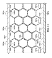
- FIG. 15 a method of bonding a composite core member to a structural component of a core stiffened structure is described and illustrated. It is conventional for the upper and lower surface networks to be adhesive bonded to upper and lower face sheets, respectively. For weight sensitive core stiffened structures, the adhesive is reticulated so as to be focused at the upper and lower surface networks. It can be desirable to also adhesively bond the side portions of the composite core to adjacent structural components; however, conventional methods of generating the requisite bondline pressure have significant shortcomings, as discussed further herein.
- One method of the present disclosure utilizes a magnetic force between either two magnets, or a magnet and a ferrous member, to create pressure at a bondline for bonding a composite core to an adjacent structure.
- a composite core 1505 is bonded to an adjacent structural component 1507 with an adhesive 1503.
- Structural component 1507 can be any variety of components, such as a web member of a structure, an airfoil spar, a clip joint, to name only a few examples.
- structural components 1507 is a non-ferrous material, thus a magnet 1501a is located on an opposite surface from the surface to which the adhesive 1503 is located.
- Magnet 1501b is located on an interior of an enclosed cell member of composite core 1505.
- magnets 1501a and 1501b attract to each other and not only act to locate the side of composite core 1505 to the tooled location of the structural component 1507, but also generate the bondline pressure to adhesive 1503 throughout the curing cycle. Once the adhesive 1503 is cured, the magnets 1501a and 1501b can be removed.
- composite core 1505 can also be bonded to another structural component 1509 in a similar style to that of component 1507; however, for illustrative purposes magnets 1501b are replaced with a magnetic strip or alternatively a strip of ferrous material. Similar to that of component 1507, component 1509 can be any variety of any variety of components, such as a web member of a structure, an airfoil spar, a clip joint, to name only a few examples.
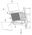
- Tooled arms can acts to position and hold structural components 1507 and 1509 in a tooled location.
- Tooling plates 1603 and 1605 can be utilized to further locate composite core 1501 within bond tool assembly.
- the magnets described in Figure 15 act to position composite core 1505 and provide bondline pressure to the adhesive during the curing cycle. After the curing cycle, the magnets can be removed and face sheets can be bonded to the upper and lower surface networks of composite core 1505.
- a conventional core stiffened structure will typically require a length and width of composite core that is carved out of a larger bulk composite core.
- the desired length and width of the composite core can sometimes leave flanges on all but one side.
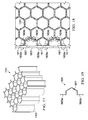
- Figure 17 illustrates an example of a composite core 1701 having only single side with flat edges of cells. It is desirable to have more than one flat cell surface for bonding to an adjacent structural component, as well as for purposes for securing the composite core during assembly and/or for purposes of machining, as discussed further herein.
- Intermediate member 1801 can be a variety of geometric configurations depending in part upon the tessellating geometry of the composite core.
- intermediate member 1801 includes to a first wall 1805a and a second wall 1805b and an insert portion 1807 therebetween.
- Insert portion 1807 fits at least partially within an exposed cell of composite core 1701, while first all 1805a and second wall 1805b fit against a surface of component 1803.
- the insert portion 1807 fits completely within the exposed cell of composite core 1701 to maximize the available bonding surfaces; however, an embodiment that doesn't require as much bonding surface may only partially attach within the exposed cell of composite core 1701.
- magnets 1809a and 1809b are utilized to generate the desired pressure at the adhesive 1811 bondline between not only component 1803 and walls 1805a and 1805b, but also between insert portion 1807 and the exposed cell of composite core 1701.
- the adhesive 1811 can be any implementation specific type of adhesive.
- the adhesive 1811 can be a paste adhesive or a film adhesive, to name a few examples.
- the pressure from the magnetic attraction can be generated by a magnet and a ferrous element rather than two magnets.
- the composite core is manufactured with a net edge surface that geometrically coincide with the surfaces of the components to which the composite core is bonded to in the core stiffened structure.
- the present disclosure contemplates at least two methods of manufacturing net edge composite core. One method involves wrapping mandrels with composite material and stacking the wrapped mandrels together in an assembly tool having a define shape, some mandrels having partial mandrel shapes to create a net edge. The other method involves using mandrels as tools such that layers of composite material are presses between layers of mandrels, at least some mandrels having a partial mandrel shape to create a net edge. These methods are described further herein.
- mandrel 2201 is a metallic mandrel, such an aluminum material.
- Mandrel 2201 is configured having a material with a relatively low coefficient of thermal expansion (CTE).
- CTE coefficient of thermal expansion
- mandrel 2201 is can be cured in a tool that utilizes pressure from the exterior to generate the desired pressure upon the composite material.
- the curing method can be configured with a material having a desired amount of CTE so that curing pressure is primarily derived from a thermal expansion of the mandrels within a confining tool.
- the curing pressure can be derived from any combination of mandrel CTE and external tooling pressure.
- Mandrel 2201 may be configured with a hollow portion 2203 extending through the centerline length of mandrel 2201, forming a body portion 2205 between hollow portion 2203 and outer surface 2207.
- Mandrel 2201 can be configured so that during the curing process of the composite core, the temperature of each mandrel 2201 is increased such that body portion 2205 volumetrically expands uniformly both in an inward direction and an outward direction, until outer surface 2207 is bounded by its nearest neighbor mandrel, at which point the pressure exerted by mandrel 2201 on its nearest neighbor mandrel remains relatively constant, and the thermal expansion of body portion 2205 continues primarily in inward direction.
- the degree of thermal expansion each mandrel 2201 is dependent upon the CTE of the material of each mandrel 2201.
- the geometry of mandrel 2201 can be selected to tailor the physical properties of mandrel 2201 and the resultant composite core. Further, the geometry of mandrel 2201 can be selected to tailor the strength/stiffness of the mandrel 2201. Further, the wall thickness of body portion 2205, as well as the geometry of hollow portion 2203, can be selectively controlled to produce a desired thermal expansion profile. For example, a mandrel having a smaller hollow portion 2203 would provide a higher external pressure than mandrel 2201. In the illustrated embodiment, hollow portion 2203 is of a cylindrical shape; however, it should be appreciated that other embodiments may have non-cylindrical shapes.
- Each mandrel 2201 can be configured with a hollow portion 2203 to allow hot air to be ducted therethrough during the cure cycle. However, it should be appreciated that an alternative embodiment of mandrel 2201 does not include a hollow portion 2203. It should be appreciated that mandrel 2201 is merely illustrative of a wide variety of mandrel configurations contemplated. Even though the exterior shape of the mandrels are illustrated as hexagonal, the present disclosure includes mandrels having other exterior shapes, such as square, rectangular, triangular, to name a few examples. Further, it should be appreciated that the hollow portion within the mandrels can be any variety of shape, or shapes. The exact shape of the hollow portion is implementation specific. Further, for the manufacturing of net edge core, the mandrel 2201 can be a partial mandrel shape. For example, the mandrel 2201 can be a half mandrel 2301, as illustrated in Figure 23 .
- each mandrel 2201 can include a layer of the bond resistant material adjacent to the outer surface 2207 of each mandrel 2201.
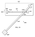
- winding jig 2005 is configured to position and retain mandrel 2201 for the depositing of composite material thereon. It should be appreciated that winding jig 2005 can take on a variety of implementation specific configurations.
- winding jig 2005 can include a driver 2009 and a support member 2011. Adapters 2013a and 2013b are operably associated with driver 2009 and support member 2011, respectively.
- a coupling 2015a is positioned between driver 2009 and a first end portion of mandrel 2201.
- a coupling 2015b is positioned between support member 2011 and a second end portion of mandrel 2201.
- Winding jig 2005 is configured to operably secure mandrel 2201 between couplings 2015a and 2015b. Couplings 2015a and 2015b have similar geometry to that of mandrel 2201. Further, winding jig 2005 is configured such that the geometry of couplings 2015a and 2015b are aligned with mandrel 2201 during the composite material winding process.
- driver 2009 is configured to drive the rotation of adapters 2013a and 2013b, couplings 2015a and 2015b, and mandrel 2201, while support member 2011 is configured to provide freewheeling support.
- mandrel 2201 and couplings 2015a and 2015b are held stationary while a device operates to place the composite material about the mandrel and couplings 2015a and 2015b, as discussed further herein.
- winding jig 2005 is merely illustrative of a fixture that can be used to facilitate the depositing of composite material onto mandrel 2201.
- Winding jig 2005 is mounted to a platform 2017 that can be translated along a prescribed path.
- a first end portion of a slit 2019 of uncured composite material can be secured to a mount 2021 that is secured to platform 2017.
- Slit 2019 is positioned through an opening 2023 in coupling 2015b.
- a second end portion of slit 2019 can remain part of a roll 2027 of composite material.
- Platform 2017 is biased in direction 2025 by a constant tension member such that slit 2019 is held in tension.
- Mount 2021 and roll 2017 are positioned so that slit 2019 is oriented at a desired angle relative to mandrel 2201. In the illustrated embodiment, the desired angle of slit 2019 is 45 degrees; however, slit 2019 can be oriented at any desired angle.
- driver 2009 is operated so as to cause mandrel 2201 to rotate, which causes slit 2019 to wrap around mandrel 2201. As slit 2019 wraps around mandrel 2201, platform 2017 is pulled toward roll 2017 in direction 2029 while the wrap angle is maintained.
- winding jig 2005 can be configured in any variety of implementation specific configurations.
- mandrel 2201 can rotate in a first rotational direction while a material placement head rotates around mandrel 2201 in an opposite direction to that of the first rotational direction.
- either mandrel 2201 can translate along its axis or the material placement head can translate in a direction corresponding to the mandrel axis, or any combination thereof.
- FIG. 23 one example embodiment of a curing tool 2303 for the manufacturing of a net edge core is illustrated, such as net edge core 2401 shown in Figure 24 .
- Curing tool 2303 is illustrated with an upper mold 2305 and a lower mold 2311; however, it should be appreciated that curing tool 2303 can include side tools.
- the desired side edges of the net edge core that don't already coincide with a flat edge of the core are labeled as first edge 2307a and second edge 2307b.
- alternative embodiments of net edge core can include any number of edges that don't have a natural edge from a cell wall.
- one or more interior partial mandrels 2301a having composite material associated therewith are pressed against one ore more outer partial mandrels 2301b also having composite material associated therewith.
- the partial mandrels 2301b are wrapped with non-bonding material, or dummy material, so the material associated with partial mandrel 2301b doesn't bond with the composite material associated with partial mandrel 2301a, which therefore prevents a subsequent post-cure trimming operation.
- Spacer mandrels 2309 can be utilized to insure adequate pressure on the composite material associated with partial mandrels 2301a and 2301b.
- the assembly can then be cured at the requisite temperature and duration. Pressure can be applied from the tooling, such as upper and lower molds 2305 and 2511, and/or from the thermal expansion of the mandrels.
- Curing tool 2303 can also be utilized to manufacturing a net edge core, such as net edge core 2401, by the process of sequentially laying up layers of composite material between the mandrels rather than wrapping the mandrels.
- Net edge core 2401 is illustrated.
- Net edge core 2401 is illustrative of a core derived from the tooled assembly illustrated in Figure 23 .
- the mandrels can be removed, and then the composite material outside of first edge 2307a and second edge 2307b can be trimmed to produce the net edge core 2401.
- Net edge core 2401 as illustrated, has natural flat surfaces 2403 and 2405 from the flat hexagonal surfaces of the cell walls.
- flat surfaces 2407 and 2407 are derived from the use of partial mandrels, such as partial mandrels 2301a and 2301b.
- net edge core 2401 is bonded to adjacent structural components 2501, 2503, 2505, and 2507 with an adhesive 2509.
- Structural components 2501, 2503, 2505, and 2507 can be any variety of components.
- components 2501 and 2503 are spar members for an airfoil structure, while components 2505 and 2507 are rib members for the airfoil structure.
- a magnet 2511a is located on an opposite surface from the surface to which the adhesive 2509 is located.
- Magnet 2511b is located on an interior of the flat outer surface of net edge core 2401.
- Manufacturing net edge core as well as using magnets to generate bond line pressure when bonding net edge core to components within an assembly, have significant advantages over conventional methods and structures. For example, utilizing net edge core allows the core to be bonded on all surfaces and to be controlled more precisely at the location of the edges and contours. Further, utilizing net edge core increases the bonding surface area and provides more consistent pressure at the bonding locations. Further, utilizing net edge core eliminates loose edges and flanges that are difficult to machine and set up for machining. Further, utilizing net edge core eliminates a need to machine exposed flanges and reduces waste during fabrication. Further, manufacturing net edge core allows multiple net edge cores to be bonded together to form a larger net edge core by greatly simplifying the splicing of two or more net edge cores together.
- magnets can be inserted deep into the net edge core, whereas mechanical devices have geometric limitations. Further, magnets can provide uniform clamping pressure at the bondline along the entire length of the magnet; whereas mechanical devices, such as spring loaded clips can provide unequal pressure. Further, magnets are low profile and can be located so as to not protrude out of the surface network, thus allowing the adhesive to be co-cured with other components of a core stiffened composite structure.
Landscapes
- Engineering & Computer Science (AREA)
- Mechanical Engineering (AREA)
- Textile Engineering (AREA)
- Physics & Mathematics (AREA)
- Fluid Mechanics (AREA)
- Moulding By Coating Moulds (AREA)
- Laminated Bodies (AREA)
Abstract
Description
- One method of the present disclosure relates to the splicing together of composite core using magnets to provide the requisite pressure at the bondline.
- Another method of the present disclosure relates to the use of magnets to secure composite core during a machining process or an assembly process.
- Another method of the present disclosure relates to manufacturing net edge core as well as a method of bonding net edge core to a substructure.
- One conventional method of splicing together composite core includes using mechanical clips that apply pressure at the adhesive bondline; however this method is not very effective at large distances from an open edge because the spring force has to be transferred by lever arms over a distance. Additionally, the mechanical clips can interfere with tooling. Another conventional method includes using an expandable foam adhesive that doesn't require artificial pressure at the bondline; however, expandable foam adhesive can be weight prohibitive.
- There is a need for an improved method of splicing together composite core.
- In a conventional composite core machining process, the composite core is machined to a desired contour for usage in a composite structure. However, the natural instability of the composite core can create high scrap rates and/or require using a machine feed rate low enough to prevent damage to the unstable composite core. Further, an assembly process for a core stiffened structure can also require the securing of the composite core.
- There is a need for an improved method of securing composite core during a core machining process or a core assembly process.
- A conventional core stiffened structure will typically require a length and width of composite core that is carved out of a larger bulk composite core. The desired length and width of the composite core can sometimes leave flanges rather than flat edges. The flanges are difficult to bond to adjacent substructure.
- There is a need for an improved method for manufacturing a more efficient core as well as a method of bonding the core to substructure.
- The novel features believed characteristic of the embodiments of the present disclosure are set forth in the appended claims. However, the embodiments themselves, as well as a preferred mode of use, and further objectives and advantages thereof, will best be understood by reference to the following detailed description when read in conjunction with the accompanying drawings, wherein:
-
Figure 1 is a side view of a illustrative rotorcraft; -
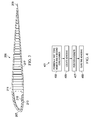
Figure 2 is a top view of a rotor blade, according to an illustrative embodiment; -
Figure 3 is a cross-sectional view of the rotor blade, taken from section lines 3-3 inFigure 2 ; -
Figure 4 is a schematic view of a method of splicing together one or more sections of core material is schematically illustrated; -
Figure 5 is a top view of sections of core material being spliced together, according to an example embodiment; -
Figure 6 is a top view of sections of core material being spliced together, according to an example embodiment; -
Figure 7 is a top view of sections of core material being spliced together, according to an example embodiment; -
Figure 8 is a top view of sections of core material being spliced together, according to an example embodiment; -
Figure 9 is a top view of sections of core material being spliced together, according to an example embodiment; -
Figure 10 is a top view of sections of core material being spliced together, according to an example embodiment; -
Figure 11 is a perspective view of composite core, according to an example embodiment; -
Figure 12 is a perspective view of carved composite core, according to an example embodiment; -
Figure 13 is a top view of composite core secured in a fixture for machining, according to an example embodiment; -
Figure 14 is a perspective view of composite core secured in a fixture for machining, according to an example embodiment; -
Figure 15 is a top view of a composite core in a bonding fixture for the bonding of the composite core to a substructure, according to an example embodiment; -
Figure 16 is a perspective view of a composite core in a bonding fixture for the bonding of the composite core to a substructure, according to an example embodiment; -
Figure 17 is a perspective view of a composite core, according to an example embodiment; -
Figure 18 is a top view of a composite core being bonded to a substructure with an intermediate member, according to one example embodiment; -
Figure 19 is a top view of an intermediate member, according to one example embodiment; -
Figure 20 is a top view of a winding jig for the manufacturing of net edge composite core, according to one example embodiment; -
Figure 21 is a top view of a winding jig for the manufacturing of net edge composite core, according to one example embodiment; -
Figure 22 is a cross-sectional view of a composite wrapped mandrel for the manufacturing of net edge composite core, take from section lines 22-22 inFigure 21 , according to one example embodiment; -
Figure 23 is a side view of a curing tool for the manufacturing of a net edge core, according to one example embodiment; -
Figure 24 is a top view of net edge core, according to an example embodiment; and -
Figure 25 is a top view of net edge core being bonded to substructure of a core stiffened structure, according to an example embodiment. - Illustrative embodiments of the present disclosure are described below. In the interest of clarity, all features of an actual implementation may not be described in this specification. It will of course be appreciated that in the development of any such actual embodiment, numerous implementation-specific decisions must be made to achieve the developer's specific goals, such as compliance with system-related and business-related constraints, which will vary from one implementation to another. Moreover, it will be appreciated that such a development effort might be complex and time-consuming but would nevertheless be a routine undertaking for those of ordinary skill in the art having the benefit of this disclosure.
- In the specification, reference may be made to the spatial relationships between various components and to the spatial orientation of various aspects of components as the devices are depicted in the attached drawings. However, as will be recognized by those skilled in the art after a complete reading of the present application, the devices, members, apparatuses, etc. described herein may be positioned in any desired orientation. Thus, the use of terms such as "above," "below," "upper," "lower," or other like terms to describe a spatial relationship between various components or to describe the spatial orientation of aspects of such components should be understood to describe a relative relationship between the components or a spatial orientation of aspects of such components, respectively, as the device described herein may be oriented in any desired direction.
- Referring now to
Figure 1 in the drawings, arotorcraft 101 is illustrated. Rotorcraft 101 has arotor system 103 with a plurality ofrotor blades 205. The pitch of eachrotor blade 205 can be manipulated in order to selectively control direction, thrust, and lift ofrotorcraft 101. Rotorcraft 101 can further include afuselage 107,anti-torque system 109, and anempennage 111. A variety of members onrotorcraft 101 can be manufacturing as a composite core (such as honeycomb core) stiffened structure, as discussed further herein. - Referring now also to
Figures 2 and3 ,rotor blade 205 is an example of a rotorcraft member than can be configured with core to efficiently provide strength and stiffness.Rotor blade 205 can include a leadingedge portion 207, atrailing edge portion 209, aroot end portion 203, and atip end portion 205. In the illustrated embodiment, anupper skin 211 and alower skin 213 form an aerodynamic surface with aspar member 215 and acore member 217 forming the internal structure. - It should be appreciated that
rotorcraft 101 is merely illustrative of an aircraft for with which one or more methods of the present disclosure can be utilized with regard to. Further,rotor blade 205 is merely illustrative of the wide variety of core stiffened structures that can utilize one or methods disclosed herein. In another embodiment, ahorizontal stabilizer 115 is the core stiffened structure, for example. - Referring now also to
Figure 4 , amethod 401 of splicing together one or more sections of core material is schematically illustrated. During fabrication of a core stiffened structure, such ascore member 217 inrotor blade 205, it can be necessary to splice one or more sections of core material together. This can be because raw composite core may not be available or practical to be made in sections long enough for arotor blade 205. However, conventional methods of splicing core material have significant deficiencies, as described further herein. -
Method 401 can include astep 403 of positioning a first core member adjacent to a second core member. Step 403 can be implemented in a variety of environments. For example, tooling can be used for aligning a first core member adjacent to second core member; however, tooling is not necessarily required. Astep 405 can include locating and adhesive on certain portions of the first core member and/or the second core member. Astep 407 can include positioning magnets to apply a pressure to the adhesive. Astep 409 can include curing the adhesive.Method 401 and the associated steps are described further herein. - Referring now also to
Figure 5 , an embodiment ofmethod 401 is described in further detail. Afirst core member 501 hasflanges 501a exposed from the manufacturing or trimming of thefirst core member 501. Similarly, second core member 503 hasflanges 503a exposed from the manufacturing or trimming of the second core member 503. During thesplicing method 401, an adhesive 507 deposited on one or both of the adjacent surfaces offlanges first magnet 505a and asecond magnet 505b can be located adjacent to the outer surfaces offlanges - Referring now also to
Figure 6 , another embodiment ofmethod 401 is described in further detail. Afirst core member 601 has "Y"flanges 601a created from the manufacturing or trimming of thefirst core member 601. Each "Y"flange 601a has multiple leg members. Similarly,second core member 603 has "Y"flanges 603a exposed from the manufacturing or trimming of thesecond core member 603. Each "Y"flange 603a has multiple leg members. The "Y"flange splicing method 401, an adhesive 607 is deposited on the adjacent surfaces of each leg member offlange 601a and on the adjacent surfaces of each leg member offlange 603a. The adhesive 607 can be any implementation specific type of adhesive. The adhesive 607 can be a paste adhesive or a film adhesive, to name a few examples. Afirst magnet 605a and asecond magnet 605b can be located adjacent to the outer surfaces of each leg member of eachflange - Referring now also to
Figures 7 and 8 , another embodiment ofmethod 401 is described in further detail. Afirst core member 701 does not have exposed flanges, but rather outer surfaces of enclosed cell members created from the manufacturing or trimming of thefirst core member 701. Similarly,second core member 703 does not have exposed flanges, but rather enclosed cell members created from the manufacturing or trimming of thesecond core member 701. During thesplicing method 401, an adhesive 707 is deposited on at least one of the outer adjacent surfacesfirst core member 701 andsecond core member 703. The adhesive 707 can be any implementation specific type of adhesive. The adhesive 707 can be a paste adhesive or a film adhesive, to name a few examples. Afirst magnet 705a and asecond magnet 705b can be located on the interior side adjacent to the outer surfacesfirst core member 701 andsecond core member 703 in order to apply bondline pressure. Thefirst magnet 705a and asecond magnet 705b can be geometrically shaped to correspond with the interior shape of the cell members. For example, the magnets can be three edges to correspond with half a hexagonal shape. - In another embodiment, the pressure from the magnet attraction is generated by a magnet and a ferrous element. The magnet can be a strip of magnetic material that has a length corresponding with the depth of the composite core. The specific magnet type, geometry, and material can be implementation specific depending in part on the desired pressure at the bondline. The magnet can be a permanent magnet or an electromagnet, for example.
- Referring now also to
Figure 9 , an embodiment ofmethod 401 is described in further detail. Afirst core member 901 hasflanges 901a exposed from the manufacturing or trimming of thefirst core member 901. Similarly,second core member 903 hasflanges 903a exposed from the manufacturing or trimming of thesecond core member 903. During thesplicing method 401, an adhesive 907 is deposited on one or both of the adjacent surfaces offlanges first magnet 905a and asecond magnet 905b can be located adjacent to the outer surfaces offlanges - Referring now also to
Figure 10 , an embodiment ofmethod 401 is described in further detail. Aribbon 1001 can be spliced onto an existing core member, or even a plurality ofribbons 1001 can be joined together to form a core. During thesplicing method 401, an adhesive 1007 is deposited on one or multiple of the surfaces of theribbons 1001 at the locations where theribbons 1001 are adjacent to each other. The adhesive 1007 can be any implementation specific type of adhesive. The adhesive 1007 can be a paste adhesive or a film adhesive, to name a few examples. Afirst magnet 1005a and asecond magnet 1005b can be located adjacent to the outer surfaces ofribbons 1001 in order to apply bondline pressure. In another embodiment, the pressure from the magnetic attraction is generated by a magnet and a ferrous element. The magnet can be a strip of magnetic material that has a length corresponding with the depth of the composite core. The specific magnet type and material can be implementation specific depending in part on the desired pressure at the bondline. The magnet can be a permanent magnet or an electromagnet, for example. - The use of magnets to create pressure at an adhesive bondline for splicing or joining composite core has significant advantages. For example, magnets can be inserted deep into the composite core block, whereas mechanical devices have geometric limitations. In one example embodiment, the magnet can be covered with a low friction material, such as Teflon® tape, to allow the magnet to reduce friction as the magnet is slipped into position within the cell of the core. Further, magnets can provide uniform clamping pressure at the bondline along the entire length of the magnet; whereas mechanical devices, such as spring loaded clips can provide unequal pressure. Further, magnets are low profile and can be located so as to not protrude out of the surface network, thus allowing the adhesive to be co-cured with other components of a core stiffened composite structure.
- Referring now to
Figure 11 , acomposite core 1101 is illustrated in a raw stock configuration. Composite core 217 (shown inFigure 3 ), having implementation specific geometry, can be carved fromcomposite core 1101, for example.Composite core 1101 can be of a wide variety of materials and cell sizes. For example, in oneembodiment composite core 1101 is made from a carbon fiber and resin composite system.Composite core 1101 includes a plurality of tubes 1103 (only one tube labeled for clarity) arranged in a two-dimensional array. However, in one embodiment thetubes 1103 can be selectively positioned such that the end portions are not in the same plane. Eachtube 1103 defines a passageway or "cell" 1105 extending therethrough.Composite core 1101 can comprise any suitable number, size, cross-sectional shape, and construction oftubes 1103. - Each
tube 1103 ofcomposite core 1101 can include a plurality of reinforcement fibers disposed in a polymeric matrix. For example,tubes 1103 may comprise fibers comprising one or more of carbon, graphite, glass, an aromatic polyamide (i.e., "aramid") material, a variant of an aromatic polyamide material (e.g., a polyparaphenylene terephthalamide material, such as Kevlar® by E. I. du Pont de Nemours and Company of Richmond, Virginia), or the like. The scope of the present disclosure, however, encompasses fibers comprising any suitable material or combination of materials. The polymeric matrix may comprise any suitable resin system, such as a thermoplastic or thermosetting resin for example. Exemplary resins include epoxy, polyimide, polyamide, bismaleimide, polyester, vinyl ester, phenolic, polyetheretherketone (PEEK), polyetherketone (PEK), polyphenylene sulfide (PPS), polyetherimide (PEI), and the like. - The fibers of
tubes 1103 may be oriented in one or more directions and can be woven, unwoven, or braided, for example. It should be appreciated thattube 1103 may alternatively only include fibers arranged in a single direction, such as a uniaxial or helical fiber configurations. In yet another embodiment, a first ply comprises fibers and a second ply comprises fibers, such that the second ply is laid-up over the first ply. - Referring now also to
Figure 12 , carvedcomposite core 1201 is illustrated. Carvedcomposite core 1201 has anupper contour 1203 and alower contour 1205. Carvedcomposite core 1201 can be used in a rotor blade, similar tocomposite core 217 shown inFigure 3 . - Referring now also to
Figure 13 , acomposite core 1101 in atool 1301 is illustrated.Tool 1301 can have afirst flange 1303 and asecond flange 1305 made with ferrous material.Magnets 1307 are located on the interior of the outside cell walls so as to attract toward the ferrousfirst flange 1303 andsecond flange 1305, thereby securing the edges of thecomposite core 1101 to the tool.Composite core 1101 can be carved in order create the desired contour. In one example, thecomposite core 1101 is machined to create the desired contour; however, thecomposite core 1101 can be carved using other methods as well. - Referring also to
Figure 14 , a carvedcomposite core 1201 is illustrated while intool 1301.Magnets 1305 act to secure thecomposite core 1201 tofirst flange 1303 andsecond flange 1305 during the machining process, thus insuring the carvedcomposite core 1201 has the desired dimensions. - In another example embodiment,
magnets 1305 are actually ferrous metal members whilefirst flange 1303 andsecond flange 1305 are magnetic members. Further, it should be appreciated thatmagnets 1305 withincomposite core 1201 cell members, and components oftool 1301, such asflanges composite core 1201 withintool 1301. Further, it should be appreciated that carvedcomposite core 1201 andtool 1301 can take on a wide variety of shapes, sizes, contours, etc. For example, a carvedcomposite core 1201 for a rotor blade 205 (shown inFigure 1 ) will have a substantially different geometry as compared to a carvedcomposite core 1201 for a panel 113 (shown inFigure 1 ). - Referring now to
Figure 15 , a method of bonding a composite core member to a structural component of a core stiffened structure is described and illustrated. It is conventional for the upper and lower surface networks to be adhesive bonded to upper and lower face sheets, respectively. For weight sensitive core stiffened structures, the adhesive is reticulated so as to be focused at the upper and lower surface networks. It can be desirable to also adhesively bond the side portions of the composite core to adjacent structural components; however, conventional methods of generating the requisite bondline pressure have significant shortcomings, as discussed further herein. - One method of the present disclosure utilizes a magnetic force between either two magnets, or a magnet and a ferrous member, to create pressure at a bondline for bonding a composite core to an adjacent structure. In the example embodiment, a
composite core 1505 is bonded to an adjacentstructural component 1507 with an adhesive 1503.Structural component 1507 can be any variety of components, such as a web member of a structure, an airfoil spar, a clip joint, to name only a few examples. On most circumstances,structural components 1507 is a non-ferrous material, thus amagnet 1501a is located on an opposite surface from the surface to which the adhesive 1503 is located.Magnet 1501b is located on an interior of an enclosed cell member ofcomposite core 1505. Thus,magnets composite core 1505 to the tooled location of thestructural component 1507, but also generate the bondline pressure to adhesive 1503 throughout the curing cycle. Once the adhesive 1503 is cured, themagnets - Still referring to
Figure 15 ,composite core 1505 can also be bonded to anotherstructural component 1509 in a similar style to that ofcomponent 1507; however, forillustrative purposes magnets 1501b are replaced with a magnetic strip or alternatively a strip of ferrous material. Similar to that ofcomponent 1507,component 1509 can be any variety of any variety of components, such as a web member of a structure, an airfoil spar, a clip joint, to name only a few examples. - Referring now also to
Figure 16 , an examplebond tool assembly 1601 is illustrated. Tooled arms can acts to position and holdstructural components Tooling plates Figure 15 act to positioncomposite core 1505 and provide bondline pressure to the adhesive during the curing cycle. After the curing cycle, the magnets can be removed and face sheets can be bonded to the upper and lower surface networks ofcomposite core 1505. - Referring now to
Figure 17 , a conventional core stiffened structure will typically require a length and width of composite core that is carved out of a larger bulk composite core. The desired length and width of the composite core can sometimes leave flanges on all but one side. For example,Figure 17 illustrates an example of acomposite core 1701 having only single side with flat edges of cells. It is desirable to have more than one flat cell surface for bonding to an adjacent structural component, as well as for purposes for securing the composite core during assembly and/or for purposes of machining, as discussed further herein. - Referring now also to
Figures 18 and 19 , a method for bonding composite core have exposed flanges, such ascomposite core 1701, to acomponent 1803 in a core stiffened structure is described and illustrated. Anintermediate member 1801 is bonded betweencomponent 1803 andcomposite core 1701. -
Intermediate member 1801 can be a variety of geometric configurations depending in part upon the tessellating geometry of the composite core. In the example embodiment,intermediate member 1801 includes to afirst wall 1805a and asecond wall 1805b and aninsert portion 1807 therebetween.Insert portion 1807 fits at least partially within an exposed cell ofcomposite core 1701, while first all 1805a andsecond wall 1805b fit against a surface ofcomponent 1803. In the example embodiment, theinsert portion 1807 fits completely within the exposed cell ofcomposite core 1701 to maximize the available bonding surfaces; however, an embodiment that doesn't require as much bonding surface may only partially attach within the exposed cell ofcomposite core 1701. - In the example embodiment,
magnets component 1803 andwalls insert portion 1807 and the exposed cell ofcomposite core 1701. As discussed further herein, the adhesive 1811 can be any implementation specific type of adhesive. The adhesive 1811 can be a paste adhesive or a film adhesive, to name a few examples. Further, the pressure from the magnetic attraction can be generated by a magnet and a ferrous element rather than two magnets. - In another method of the present disclosure, rather than the composite core being cut from a bulk composite core to fit within a geometry specific core stiffened structure, the composite core is manufactured with a net edge surface that geometrically coincide with the surfaces of the components to which the composite core is bonded to in the core stiffened structure. The present disclosure contemplates at least two methods of manufacturing net edge composite core. One method involves wrapping mandrels with composite material and stacking the wrapped mandrels together in an assembly tool having a define shape, some mandrels having partial mandrel shapes to create a net edge. The other method involves using mandrels as tools such that layers of composite material are presses between layers of mandrels, at least some mandrels having a partial mandrel shape to create a net edge. These methods are described further herein.
- Referring now to
Figures 20-22 , one example embodiment for wrapping mandrels with composite material for the manufacturing of net edge core is described and illustrated. - Referring to
Figure 22 , a cross-sectional view through amandrel 2201 is illustrated. In the illustrated embodiment,mandrel 2201 is a metallic mandrel, such an aluminum material.Mandrel 2201 is configured having a material with a relatively low coefficient of thermal expansion (CTE). In the illustrated embodiment,mandrel 2201 is can be cured in a tool that utilizes pressure from the exterior to generate the desired pressure upon the composite material. However, it should be appreciated that the curing method can be configured with a material having a desired amount of CTE so that curing pressure is primarily derived from a thermal expansion of the mandrels within a confining tool. In another embodiment, the curing pressure can be derived from any combination of mandrel CTE and external tooling pressure. -
Mandrel 2201 may be configured with a hollow portion 2203 extending through the centerline length ofmandrel 2201, forming a body portion 2205 between hollow portion 2203 and outer surface 2207.Mandrel 2201 can be configured so that during the curing process of the composite core, the temperature of eachmandrel 2201 is increased such that body portion 2205 volumetrically expands uniformly both in an inward direction and an outward direction, until outer surface 2207 is bounded by its nearest neighbor mandrel, at which point the pressure exerted bymandrel 2201 on its nearest neighbor mandrel remains relatively constant, and the thermal expansion of body portion 2205 continues primarily in inward direction. The degree of thermal expansion eachmandrel 2201 is dependent upon the CTE of the material of eachmandrel 2201. The geometry ofmandrel 2201 can be selected to tailor the physical properties ofmandrel 2201 and the resultant composite core. Further, the geometry ofmandrel 2201 can be selected to tailor the strength/stiffness of themandrel 2201. Further, the wall thickness of body portion 2205, as well as the geometry of hollow portion 2203, can be selectively controlled to produce a desired thermal expansion profile. For example, a mandrel having a smaller hollow portion 2203 would provide a higher external pressure thanmandrel 2201. In the illustrated embodiment, hollow portion 2203 is of a cylindrical shape; however, it should be appreciated that other embodiments may have non-cylindrical shapes. - Each
mandrel 2201 can be configured with a hollow portion 2203 to allow hot air to be ducted therethrough during the cure cycle. However, it should be appreciated that an alternative embodiment ofmandrel 2201 does not include a hollow portion 2203. It should be appreciated thatmandrel 2201 is merely illustrative of a wide variety of mandrel configurations contemplated. Even though the exterior shape of the mandrels are illustrated as hexagonal, the present disclosure includes mandrels having other exterior shapes, such as square, rectangular, triangular, to name a few examples. Further, it should be appreciated that the hollow portion within the mandrels can be any variety of shape, or shapes. The exact shape of the hollow portion is implementation specific. Further, for the manufacturing of net edge core, themandrel 2201 can be a partial mandrel shape. For example, themandrel 2201 can be a half mandrel 2301, as illustrated inFigure 23 . - In one example embodiment, a Teflon® material, or other bond resistant material or coating, can be used to prevent the composite material from bonding to the exterior surface of
mandrel 2201 during the cure cycle. As such, eachmandrel 2201 can include a layer of the bond resistant material adjacent to the outer surface 2207 of eachmandrel 2201. - Referring now also to
Figures 20 and21 , an example method of wrapping amandrel 2201 is described and illustrated. The exact method of wrapping or otherwise depositing the uncured composite material on eachmandrel 2201 is implementation specific. An embodiment of a windingjig 2005 is illustrated. Windingjig 2005 is configured to position and retainmandrel 2201 for the depositing of composite material thereon. It should be appreciated that windingjig 2005 can take on a variety of implementation specific configurations. In one embodiment, windingjig 2005 can include adriver 2009 and asupport member 2011. Adapters 2013a and 2013b are operably associated withdriver 2009 andsupport member 2011, respectively. Acoupling 2015a is positioned betweendriver 2009 and a first end portion ofmandrel 2201. Similarly, acoupling 2015b is positioned betweensupport member 2011 and a second end portion ofmandrel 2201. - Winding
jig 2005 is configured to operablysecure mandrel 2201 betweencouplings Couplings mandrel 2201. Further, windingjig 2005 is configured such that the geometry ofcouplings mandrel 2201 during the composite material winding process. In the illustrated embodiment,driver 2009 is configured to drive the rotation of adapters 2013a and 2013b,couplings mandrel 2201, whilesupport member 2011 is configured to provide freewheeling support. In an alternative embodiment,mandrel 2201 andcouplings couplings jig 2005 is merely illustrative of a fixture that can be used to facilitate the depositing of composite material ontomandrel 2201. - Winding
jig 2005 is mounted to aplatform 2017 that can be translated along a prescribed path. A first end portion of aslit 2019 of uncured composite material can be secured to amount 2021 that is secured toplatform 2017.Slit 2019 is positioned through anopening 2023 incoupling 2015b. A second end portion ofslit 2019 can remain part of aroll 2027 of composite material.Platform 2017 is biased indirection 2025 by a constant tension member such that slit 2019 is held in tension.Mount 2021 androll 2017 are positioned so thatslit 2019 is oriented at a desired angle relative tomandrel 2201. In the illustrated embodiment, the desired angle ofslit 2019 is 45 degrees; however, slit 2019 can be oriented at any desired angle. - During operation,
driver 2009 is operated so as to causemandrel 2201 to rotate, which causes slit 2019 to wrap aroundmandrel 2201. Asslit 2019 wraps aroundmandrel 2201,platform 2017 is pulled towardroll 2017 indirection 2029 while the wrap angle is maintained. - It should be appreciated that the winding
jig 2005 can be configured in any variety of implementation specific configurations. For example,mandrel 2201 can rotate in a first rotational direction while a material placement head rotates aroundmandrel 2201 in an opposite direction to that of the first rotational direction. Further, eithermandrel 2201 can translate along its axis or the material placement head can translate in a direction corresponding to the mandrel axis, or any combination thereof. - Referring now also to
Figure 23 , one example embodiment of acuring tool 2303 for the manufacturing of a net edge core is illustrated, such asnet edge core 2401 shown inFigure 24 .Curing tool 2303 is illustrated with anupper mold 2305 and alower mold 2311; however, it should be appreciated that curingtool 2303 can include side tools. In the illustrated embodiment, the desired side edges of the net edge core that don't already coincide with a flat edge of the core are labeled asfirst edge 2307a andsecond edge 2307b. It should be appreciated that alternative embodiments of net edge core can include any number of edges that don't have a natural edge from a cell wall. In order to create the desired flat surfaces at an edge, such asfirst edge 2307a, one or more interior partial mandrels 2301a having composite material associated therewith are pressed against one ore more outer partial mandrels 2301b also having composite material associated therewith. In another embodiment, the partial mandrels 2301b are wrapped with non-bonding material, or dummy material, so the material associated with partial mandrel 2301b doesn't bond with the composite material associated with partial mandrel 2301a, which therefore prevents a subsequent post-cure trimming operation.Spacer mandrels 2309 can be utilized to insure adequate pressure on the composite material associated with partial mandrels 2301a and 2301b. The assembly can then be cured at the requisite temperature and duration. Pressure can be applied from the tooling, such as upper andlower molds 2305 and 2511, and/or from the thermal expansion of the mandrels. -
Curing tool 2303 can also be utilized to manufacturing a net edge core, such asnet edge core 2401, by the process of sequentially laying up layers of composite material between the mandrels rather than wrapping the mandrels. - Referring now also to
Figure 24 , anet edge core 2401 is illustrated.Net edge core 2401 is illustrative of a core derived from the tooled assembly illustrated inFigure 23 . After the curing cycle is completed, the mandrels can be removed, and then the composite material outside offirst edge 2307a andsecond edge 2307b can be trimmed to produce thenet edge core 2401.Net edge core 2401, as illustrated, has naturalflat surfaces flat surfaces - Referring now also to
Figure 25 , a method of bondingnet edge core 2401 to substructure is illustrated. One method of the present disclosure utilizes a magnetic force between either two magnets, or a magnet and a ferrous member, to create pressure at a bondline for bonding a composite core to an adjacent structure. In the example embodiment,net edge core 2401 is bonded to adjacentstructural components Structural components components components - At each bonding location, a
magnet 2511a is located on an opposite surface from the surface to which the adhesive 2509 is located.Magnet 2511b is located on an interior of the flat outer surface ofnet edge core 2401. Thus,magnets composite core 2401 to the tooled location of thestructural components magnets - Manufacturing net edge core, as well as using magnets to generate bond line pressure when bonding net edge core to components within an assembly, have significant advantages over conventional methods and structures. For example, utilizing net edge core allows the core to be bonded on all surfaces and to be controlled more precisely at the location of the edges and contours. Further, utilizing net edge core increases the bonding surface area and provides more consistent pressure at the bonding locations. Further, utilizing net edge core eliminates loose edges and flanges that are difficult to machine and set up for machining. Further, utilizing net edge core eliminates a need to machine exposed flanges and reduces waste during fabrication. Further, manufacturing net edge core allows multiple net edge cores to be bonded together to form a larger net edge core by greatly simplifying the splicing of two or more net edge cores together.
- Further, utilizing magnets to generate bondline pressure when bonding net edge core to substructure also has significant advantages. For example, magnets can be inserted deep into the net edge core, whereas mechanical devices have geometric limitations. Further, magnets can provide uniform clamping pressure at the bondline along the entire length of the magnet; whereas mechanical devices, such as spring loaded clips can provide unequal pressure. Further, magnets are low profile and can be located so as to not protrude out of the surface network, thus allowing the adhesive to be co-cured with other components of a core stiffened composite structure.
- The particular embodiments disclosed above are illustrative only, as the apparatus may be modified and practiced in different but equivalent manners apparent to those skilled in the art having the benefit of the teachings herein. Modifications, additions, or omissions may be made to the apparatuses described herein without departing from the scope of the invention. The components of the apparatus may be integrated or separated. Moreover, the operations of the apparatus may be performed by more, fewer, or other components.
- Furthermore, no limitations are intended to the details of construction or design herein shown, other than as described in the claims below. It is therefore evident that the particular embodiments disclosed above may be altered or modified and all such variations are considered within the scope and spirit of the application. Accordingly, the protection sought herein is as set forth in the claims below.
- To aid the Patent Office, and any readers of any patent issued on this application in interpreting the claims appended hereto, applicants wish to note that they do not intend any of the appended claims to invoke paragraph 6 of 35 U.S.C. § 112 as it exists on the date of filing hereof unless the words "means for" or "step for" are explicitly used in the particular claim.
Claims (15)
- A method of securing a composite core in a tool, the method comprising:positioning a first edge of the composite core against a first tooled member;locating a first magnet within an outer cell member along the first edge of the composite core so that the first edge of the composite core is magnetically drawn to the first tooled member.
- The method according to claim 1, further comprising:locating a second magnet along a second edge of the composite core such that the second edge of the composite core is magnetically drawn to a second tooled member.
- A method of carving a contour surface on a composite core, the method comprising:positioning a first edge of the composite core against a first tooled member;locating a first magnet within an outer cell member along the first edge of the composite core so that the first edge of the composite core is magnetically drawn to the first tooled member;locating a second magnet along a second edge of the composite core such that the second edge of the composite core is magnetically drawn to a second tooled member; andcarving a first contour of the composite core.
- The method according to claim 1 or claim 2, wherein the first tooled member is a ferrous metal member.
- The method according to claim 3, wherein the second tooled member is a ferrous metal member; or
The method of claim 2 wherein the first tooled member and the second tooled member are ferrous metal members. - The method according to claim 1 or claim 3, or any preceding claim, wherein the composite core has hexagonal cell members.
- The method according to claim 1, wherein the first edge of the composite core includes flat cell wall layers that are parallel to a surface of the first tooled member.
- The method according to claim 1 or any of claims 2 to 7, further comprising:inserting a low friction layer between the first magnet and an inner surface of the outer cell member.
- The method according to claim 3 or any claim dependent directly or indirectly from claim 3, wherein the step of carving the first contour includes machining the composite core; or wherein the step of carving the first contour includes machining a depth of the surface network of the composite core.
- The method according to claim 3 or any preceding claim, wherein the first magnet is an electromagnet.
- A method of manufacturing a composite core, the method comprising:orienting a first core ribbon;orienting a second core ribbon opposite to the first core ribbon;applying an adhesive between abutting flat surfaces of the first core ribbon and the second core ribbon;utilizing a magnet and a member to generate a pressure on the adhesive.
- The method according to claim 11, wherein the member is a magnet.
- The method according to claim 11 or claim 12, wherein the member is a ferrous metal.
- The method according to claim 11 or claim 12 or claim 13, wherein the composite core has hexagonal shaped cell members.
- The method according to claim 11 or any preceding claim, wherein the composite core includes a carbon fiber material.
Applications Claiming Priority (1)
| Application Number | Priority Date | Filing Date | Title |
|---|---|---|---|
| US14/136,579 US9211618B2 (en) | 2013-12-20 | 2013-12-20 | Method of securing composite core during a manufacturing process |
Publications (2)
| Publication Number | Publication Date |
|---|---|
| EP2886251A1 true EP2886251A1 (en) | 2015-06-24 |
| EP2886251B1 EP2886251B1 (en) | 2017-02-01 |
Family
ID=50072908
Family Applications (1)
| Application Number | Title | Priority Date | Filing Date |
|---|---|---|---|
| EP14153870.2A Active EP2886251B1 (en) | 2013-12-20 | 2014-02-04 | Method of securing composite core during a manufacturing process |
Country Status (2)
| Country | Link |
|---|---|
| US (1) | US9211618B2 (en) |
| EP (1) | EP2886251B1 (en) |
Cited By (2)
| Publication number | Priority date | Publication date | Assignee | Title |
|---|---|---|---|---|
| FR3111840A1 (en) * | 2020-06-25 | 2021-12-31 | Safran Aircraft Engines | One-piece metal plate reinforcement in composite material |
| FR3141964A1 (en) * | 2022-11-16 | 2024-05-17 | Safran Aircraft Engines | System for attaching an upstream acoustic shroud to a fan casing |
Families Citing this family (12)
| Publication number | Priority date | Publication date | Assignee | Title |
|---|---|---|---|---|
| JP2015082637A (en) * | 2013-10-24 | 2015-04-27 | 富士通株式会社 | Method of manufacturing component assembly and positioning device |
| US9895840B2 (en) * | 2014-05-15 | 2018-02-20 | The Boeing Company | Thermoformed cascades for jet engine thrust reversers |
| US10864658B2 (en) | 2016-02-12 | 2020-12-15 | Rohr, Inc. | Mold with integral driver blocks |
| WO2018217591A1 (en) | 2017-05-24 | 2018-11-29 | The Procter & Gamble Company | Absorbent article with raisable topsheet |
| US10823112B2 (en) | 2017-05-25 | 2020-11-03 | The Boeing Company | Method for manufacturing and assembly of a thrust reverser cascade |
| US10994856B2 (en) * | 2017-10-16 | 2021-05-04 | Rohr, Inc. | Structural panel with splice joint between adjacent core structures |
| US11491686B2 (en) | 2019-07-22 | 2022-11-08 | The Boeing Company | Compression molded cascades with two piece mold |
| CN111267452B (en) * | 2020-01-21 | 2021-02-09 | 江苏奇一科技有限公司 | Continuous honeycomb core material, honeycomb core sandwich composite panel and preparation method and equipment thereof |
| CN112123793A (en) * | 2020-08-13 | 2020-12-25 | 上海复合材料科技有限公司 | Splicing method of curved surface honeycombs |
| CN115533570B (en) * | 2022-10-20 | 2025-05-13 | 江西昌河航空工业有限公司 | A quick clamping device and method for numerical control machining of honeycomb parts |
| CN117418989A (en) * | 2023-07-20 | 2024-01-19 | 重庆大学 | Assembled fan blade |
| CN118456889A (en) * | 2024-05-08 | 2024-08-09 | 成都飞机工业(集团)有限责任公司 | Splicing method of honeycomb core parts |
Citations (1)
| Publication number | Priority date | Publication date | Assignee | Title |
|---|---|---|---|---|
| US20100071192A1 (en) * | 2008-09-19 | 2010-03-25 | Branko Sarh | Electromagnetic clamping device |
Family Cites Families (14)
| Publication number | Priority date | Publication date | Assignee | Title |
|---|---|---|---|---|
| US3366530A (en) * | 1964-03-25 | 1968-01-30 | Hexcel Corp | Color tinted plastic cellular honeycomb type structures |
| EP0244120A3 (en) | 1986-04-16 | 1989-07-12 | Courtaulds Plc | Composite element |
| US4907920A (en) * | 1989-01-18 | 1990-03-13 | The Boeing Company | Milling cutter for honeycomb core material |
| US5549773A (en) * | 1990-02-05 | 1996-08-27 | Northrop Grumman Corporation | Woven preform/magnetic press process for thermoplastic honeycomb cores |
| US5139596A (en) * | 1990-05-31 | 1992-08-18 | Basf Structural Materials, Inc. | Continuous process for the preparation of thermoplastic honeycomb |
| US6655633B1 (en) | 2000-01-21 | 2003-12-02 | W. Cullen Chapman, Jr. | Tubular members integrated to form a structure |
| JP4577960B2 (en) * | 2000-08-23 | 2010-11-10 | 本田技研工業株式会社 | Non-magnetic member joining method |
| US7243879B2 (en) | 2001-12-06 | 2007-07-17 | Kazak Composites, Incorporated | Lattice fin for missiles or other fluid-born bodies and method for producing same |
| DE04775802T1 (en) | 2003-02-24 | 2006-05-18 | Bell Helicopter Textron, Inc., Fort Worth | TOOL CONNECTION TO JOIN FIBER COMPOSITE LAMINATES |
| US8834668B2 (en) | 2008-11-19 | 2014-09-16 | The Boeing Company | Staged cocuring of composite structures |
| CA2786737C (en) | 2010-02-04 | 2016-04-19 | Bell Helicopter Textron Inc. | Composite core and method of making same |
| CN102753338B (en) | 2010-02-05 | 2015-12-02 | 贝尔直升机泰克斯特龙公司 | Manufacture the method for strengthening core structure |
| EP2646221A1 (en) | 2010-12-03 | 2013-10-09 | The Swisscore AG | Device and method for producing a honeycomb structure and a honeycomb structure |
| US8917809B2 (en) | 2012-02-28 | 2014-12-23 | Tsukasa NOZAWA | Honeycomb structure having honeycomb core arranged parallel to a panel surface and a manufacturing process therefor |
-
2013
- 2013-12-20 US US14/136,579 patent/US9211618B2/en active Active
-
2014
- 2014-02-04 EP EP14153870.2A patent/EP2886251B1/en active Active
Patent Citations (1)
| Publication number | Priority date | Publication date | Assignee | Title |
|---|---|---|---|---|
| US20100071192A1 (en) * | 2008-09-19 | 2010-03-25 | Branko Sarh | Electromagnetic clamping device |
Non-Patent Citations (1)
| Title |
|---|
| LIU ET AL: "Study on clamping method for paper honeycomb based on magnetic field and friction principle", JOURNAL OF MATERIALS PROCESSING TECHNOLOGY, ELSEVIER, NL, vol. 190, no. 1-3, 11 May 2007 (2007-05-11), pages 65 - 72, XP022070972, ISSN: 0924-0136, DOI: 10.1016/J.JMATPROTEC.2006.10.052 * |
Cited By (2)
| Publication number | Priority date | Publication date | Assignee | Title |
|---|---|---|---|---|
| FR3111840A1 (en) * | 2020-06-25 | 2021-12-31 | Safran Aircraft Engines | One-piece metal plate reinforcement in composite material |
| FR3141964A1 (en) * | 2022-11-16 | 2024-05-17 | Safran Aircraft Engines | System for attaching an upstream acoustic shroud to a fan casing |
Also Published As
| Publication number | Publication date |
|---|---|
| EP2886251B1 (en) | 2017-02-01 |
| US9211618B2 (en) | 2015-12-15 |
| US20150174717A1 (en) | 2015-06-25 |
Similar Documents
| Publication | Publication Date | Title |
|---|---|---|
| US9211618B2 (en) | Method of securing composite core during a manufacturing process | |
| CA2852585C (en) | System and method of post-cure processing of composite core | |
| US7479201B1 (en) | Method for fabricating rib-stiffened composite structures | |
| EP2886304B1 (en) | Method of splicing composite core | |
| US5248242A (en) | Aerodynamic rotor blade of composite material fabricated in one cure cycle | |
| CN104015918B (en) | Manufacture the system and method for composite core | |
| EP2772345B1 (en) | Pressure tunable expandable mandrel for manufacturing a composite structure | |
| US9017510B2 (en) | Method and apparatus for fabricating large scale integrated airfoils | |
| EP2303554B1 (en) | Tool and method for the manufacture of composite structures | |
| CN104015920A (en) | System and method of manufacturing composite core | |
| US11065775B2 (en) | System and method of post-cure processing of composite core | |
| EP2886317B1 (en) | Method of manufacturing net edge core and a method of bonding net edge core to a substructure | |
| EP2832533A1 (en) | Method of configuring composite core in a core stiffened structure and a structure incorporating the same | |
| CN104903081A (en) | Method of fabricating a curved composite structure using composite prepreg tape | |
| CN104015346B (en) | The system and method for manufacturing composite core | |
| EP4501586B1 (en) | Methods of stamp-forming fiber-reinforced thermoplastic composite assemblies and related systems | |
| WO2019245599A1 (en) | Net edge composite core splices for aircraft wing |
Legal Events
| Date | Code | Title | Description |
|---|---|---|---|
| PUAI | Public reference made under article 153(3) epc to a published international application that has entered the european phase |
Free format text: ORIGINAL CODE: 0009012 |
|
| 17P | Request for examination filed |
Effective date: 20140204 |
|
| AK | Designated contracting states |
Kind code of ref document: A1 Designated state(s): AL AT BE BG CH CY CZ DE DK EE ES FI FR GB GR HR HU IE IS IT LI LT LU LV MC MK MT NL NO PL PT RO RS SE SI SK SM TR |
|
| AX | Request for extension of the european patent |
Extension state: BA ME |
|
| GRAP | Despatch of communication of intention to grant a patent |
Free format text: ORIGINAL CODE: EPIDOSNIGR1 |
|
| RIC1 | Information provided on ipc code assigned before grant |
Ipc: B29C 53/60 20060101ALN20160721BHEP Ipc: B25B 11/00 20060101AFI20160721BHEP Ipc: B29C 65/78 20060101ALN20160721BHEP Ipc: B32B 5/02 20060101ALI20160721BHEP Ipc: B29C 65/50 20060101ALN20160721BHEP Ipc: B32B 15/14 20060101ALI20160721BHEP Ipc: B29C 65/48 20060101ALN20160721BHEP Ipc: B29L 31/60 20060101ALN20160721BHEP Ipc: B23Q 3/154 20060101ALN20160721BHEP Ipc: B32B 3/12 20060101ALI20160721BHEP Ipc: B23Q 3/15 20060101ALI20160721BHEP Ipc: B29D 99/00 20100101ALN20160721BHEP Ipc: B29L 31/08 20060101ALN20160721BHEP Ipc: B29L 31/30 20060101ALN20160721BHEP |
|
| RIC1 | Information provided on ipc code assigned before grant |
Ipc: B29D 99/00 20100101ALN20160728BHEP Ipc: B32B 15/14 20060101ALI20160728BHEP Ipc: B29C 65/48 20060101ALN20160728BHEP Ipc: B25B 11/00 20060101AFI20160728BHEP Ipc: B29L 31/08 20060101ALN20160728BHEP Ipc: B29L 31/60 20060101ALN20160728BHEP Ipc: B32B 3/12 20060101ALI20160728BHEP Ipc: B29C 53/60 20060101ALN20160728BHEP Ipc: B29C 65/50 20060101ALN20160728BHEP Ipc: B29L 31/30 20060101ALN20160728BHEP Ipc: B32B 5/02 20060101ALI20160728BHEP Ipc: B23Q 3/15 20060101ALI20160728BHEP Ipc: B23Q 3/154 20060101ALN20160728BHEP Ipc: B29C 65/78 20060101ALN20160728BHEP |
|
| INTG | Intention to grant announced |
Effective date: 20160809 |
|
| RIN1 | Information on inventor provided before grant (corrected) |
Inventor name: HETHCOCK, JAMES D. Inventor name: FREEMAN, JONATHAN A. |
|
| GRAS | Grant fee paid |
Free format text: ORIGINAL CODE: EPIDOSNIGR3 |
|
| GRAA | (expected) grant |
Free format text: ORIGINAL CODE: 0009210 |
|
| AK | Designated contracting states |
Kind code of ref document: B1 Designated state(s): AL AT BE BG CH CY CZ DE DK EE ES FI FR GB GR HR HU IE IS IT LI LT LU LV MC MK MT NL NO PL PT RO RS SE SI SK SM TR |
|
| REG | Reference to a national code |
Ref country code: GB Ref legal event code: FG4D |
|
| REG | Reference to a national code |
Ref country code: CH Ref legal event code: EP Ref country code: AT Ref legal event code: REF Ref document number: 865147 Country of ref document: AT Kind code of ref document: T Effective date: 20170215 |
|
| REG | Reference to a national code |
Ref country code: IE Ref legal event code: FG4D |
|
| REG | Reference to a national code |
Ref country code: FR Ref legal event code: PLFP Year of fee payment: 4 |
|
| REG | Reference to a national code |
Ref country code: DE Ref legal event code: R096 Ref document number: 602014006434 Country of ref document: DE |
|
| REG | Reference to a national code |
Ref country code: NL Ref legal event code: MP Effective date: 20170201 |
|
| REG | Reference to a national code |
Ref country code: LT Ref legal event code: MG4D |
|
| REG | Reference to a national code |
Ref country code: AT Ref legal event code: MK05 Ref document number: 865147 Country of ref document: AT Kind code of ref document: T Effective date: 20170201 |
|
| PG25 | Lapsed in a contracting state [announced via postgrant information from national office to epo] |
Ref country code: IS Free format text: LAPSE BECAUSE OF FAILURE TO SUBMIT A TRANSLATION OF THE DESCRIPTION OR TO PAY THE FEE WITHIN THE PRESCRIBED TIME-LIMIT Effective date: 20170601 Ref country code: FI Free format text: LAPSE BECAUSE OF FAILURE TO SUBMIT A TRANSLATION OF THE DESCRIPTION OR TO PAY THE FEE WITHIN THE PRESCRIBED TIME-LIMIT Effective date: 20170201 Ref country code: HR Free format text: LAPSE BECAUSE OF FAILURE TO SUBMIT A TRANSLATION OF THE DESCRIPTION OR TO PAY THE FEE WITHIN THE PRESCRIBED TIME-LIMIT Effective date: 20170201 Ref country code: LT Free format text: LAPSE BECAUSE OF FAILURE TO SUBMIT A TRANSLATION OF THE DESCRIPTION OR TO PAY THE FEE WITHIN THE PRESCRIBED TIME-LIMIT Effective date: 20170201 Ref country code: NO Free format text: LAPSE BECAUSE OF FAILURE TO SUBMIT A TRANSLATION OF THE DESCRIPTION OR TO PAY THE FEE WITHIN THE PRESCRIBED TIME-LIMIT Effective date: 20170501 Ref country code: GR Free format text: LAPSE BECAUSE OF FAILURE TO SUBMIT A TRANSLATION OF THE DESCRIPTION OR TO PAY THE FEE WITHIN THE PRESCRIBED TIME-LIMIT Effective date: 20170502 |
|
| PG25 | Lapsed in a contracting state [announced via postgrant information from national office to epo] |
Ref country code: ES Free format text: LAPSE BECAUSE OF FAILURE TO SUBMIT A TRANSLATION OF THE DESCRIPTION OR TO PAY THE FEE WITHIN THE PRESCRIBED TIME-LIMIT Effective date: 20170201 Ref country code: LV Free format text: LAPSE BECAUSE OF FAILURE TO SUBMIT A TRANSLATION OF THE DESCRIPTION OR TO PAY THE FEE WITHIN THE PRESCRIBED TIME-LIMIT Effective date: 20170201 Ref country code: RS Free format text: LAPSE BECAUSE OF FAILURE TO SUBMIT A TRANSLATION OF THE DESCRIPTION OR TO PAY THE FEE WITHIN THE PRESCRIBED TIME-LIMIT Effective date: 20170201 Ref country code: NL Free format text: LAPSE BECAUSE OF FAILURE TO SUBMIT A TRANSLATION OF THE DESCRIPTION OR TO PAY THE FEE WITHIN THE PRESCRIBED TIME-LIMIT Effective date: 20170201 Ref country code: BG Free format text: LAPSE BECAUSE OF FAILURE TO SUBMIT A TRANSLATION OF THE DESCRIPTION OR TO PAY THE FEE WITHIN THE PRESCRIBED TIME-LIMIT Effective date: 20170501 Ref country code: PT Free format text: LAPSE BECAUSE OF FAILURE TO SUBMIT A TRANSLATION OF THE DESCRIPTION OR TO PAY THE FEE WITHIN THE PRESCRIBED TIME-LIMIT Effective date: 20170601 Ref country code: SE Free format text: LAPSE BECAUSE OF FAILURE TO SUBMIT A TRANSLATION OF THE DESCRIPTION OR TO PAY THE FEE WITHIN THE PRESCRIBED TIME-LIMIT Effective date: 20170201 Ref country code: PL Free format text: LAPSE BECAUSE OF FAILURE TO SUBMIT A TRANSLATION OF THE DESCRIPTION OR TO PAY THE FEE WITHIN THE PRESCRIBED TIME-LIMIT Effective date: 20170201 Ref country code: AT Free format text: LAPSE BECAUSE OF FAILURE TO SUBMIT A TRANSLATION OF THE DESCRIPTION OR TO PAY THE FEE WITHIN THE PRESCRIBED TIME-LIMIT Effective date: 20170201 |
|
| REG | Reference to a national code |
Ref country code: CH Ref legal event code: PL |
|
| PG25 | Lapsed in a contracting state [announced via postgrant information from national office to epo] |
Ref country code: LI Free format text: LAPSE BECAUSE OF NON-PAYMENT OF DUE FEES Effective date: 20170228 Ref country code: RO Free format text: LAPSE BECAUSE OF FAILURE TO SUBMIT A TRANSLATION OF THE DESCRIPTION OR TO PAY THE FEE WITHIN THE PRESCRIBED TIME-LIMIT Effective date: 20170201 Ref country code: CH Free format text: LAPSE BECAUSE OF NON-PAYMENT OF DUE FEES Effective date: 20170228 Ref country code: CZ Free format text: LAPSE BECAUSE OF FAILURE TO SUBMIT A TRANSLATION OF THE DESCRIPTION OR TO PAY THE FEE WITHIN THE PRESCRIBED TIME-LIMIT Effective date: 20170201 Ref country code: EE Free format text: LAPSE BECAUSE OF FAILURE TO SUBMIT A TRANSLATION OF THE DESCRIPTION OR TO PAY THE FEE WITHIN THE PRESCRIBED TIME-LIMIT Effective date: 20170201 Ref country code: SK Free format text: LAPSE BECAUSE OF FAILURE TO SUBMIT A TRANSLATION OF THE DESCRIPTION OR TO PAY THE FEE WITHIN THE PRESCRIBED TIME-LIMIT Effective date: 20170201 |
|
| REG | Reference to a national code |
Ref country code: DE Ref legal event code: R097 Ref document number: 602014006434 Country of ref document: DE |
|
| REG | Reference to a national code |
Ref country code: IE Ref legal event code: MM4A |
|
| PG25 | Lapsed in a contracting state [announced via postgrant information from national office to epo] |
Ref country code: SM Free format text: LAPSE BECAUSE OF FAILURE TO SUBMIT A TRANSLATION OF THE DESCRIPTION OR TO PAY THE FEE WITHIN THE PRESCRIBED TIME-LIMIT Effective date: 20170201 Ref country code: MC Free format text: LAPSE BECAUSE OF FAILURE TO SUBMIT A TRANSLATION OF THE DESCRIPTION OR TO PAY THE FEE WITHIN THE PRESCRIBED TIME-LIMIT Effective date: 20170201 Ref country code: DK Free format text: LAPSE BECAUSE OF FAILURE TO SUBMIT A TRANSLATION OF THE DESCRIPTION OR TO PAY THE FEE WITHIN THE PRESCRIBED TIME-LIMIT Effective date: 20170201 |
|
| PLBE | No opposition filed within time limit |
Free format text: ORIGINAL CODE: 0009261 |
|
| STAA | Information on the status of an ep patent application or granted ep patent |
Free format text: STATUS: NO OPPOSITION FILED WITHIN TIME LIMIT |
|
| PG25 | Lapsed in a contracting state [announced via postgrant information from national office to epo] |
Ref country code: LU Free format text: LAPSE BECAUSE OF NON-PAYMENT OF DUE FEES Effective date: 20170204 |
|
| 26N | No opposition filed |
Effective date: 20171103 |
|
| REG | Reference to a national code |
Ref country code: BE Ref legal event code: MM Effective date: 20170228 |
|
| REG | Reference to a national code |
Ref country code: FR Ref legal event code: PLFP Year of fee payment: 5 |
|
| PG25 | Lapsed in a contracting state [announced via postgrant information from national office to epo] |
Ref country code: SI Free format text: LAPSE BECAUSE OF FAILURE TO SUBMIT A TRANSLATION OF THE DESCRIPTION OR TO PAY THE FEE WITHIN THE PRESCRIBED TIME-LIMIT Effective date: 20170201 Ref country code: IE Free format text: LAPSE BECAUSE OF NON-PAYMENT OF DUE FEES Effective date: 20170204 |
|
| PG25 | Lapsed in a contracting state [announced via postgrant information from national office to epo] |
Ref country code: BE Free format text: LAPSE BECAUSE OF NON-PAYMENT OF DUE FEES Effective date: 20170228 |
|
| PG25 | Lapsed in a contracting state [announced via postgrant information from national office to epo] |
Ref country code: MT Free format text: LAPSE BECAUSE OF NON-PAYMENT OF DUE FEES Effective date: 20170204 |
|
| PG25 | Lapsed in a contracting state [announced via postgrant information from national office to epo] |
Ref country code: HU Free format text: LAPSE BECAUSE OF FAILURE TO SUBMIT A TRANSLATION OF THE DESCRIPTION OR TO PAY THE FEE WITHIN THE PRESCRIBED TIME-LIMIT; INVALID AB INITIO Effective date: 20140204 |
|
| PG25 | Lapsed in a contracting state [announced via postgrant information from national office to epo] |
Ref country code: CY Free format text: LAPSE BECAUSE OF FAILURE TO SUBMIT A TRANSLATION OF THE DESCRIPTION OR TO PAY THE FEE WITHIN THE PRESCRIBED TIME-LIMIT Effective date: 20170201 |
|
| PG25 | Lapsed in a contracting state [announced via postgrant information from national office to epo] |
Ref country code: MK Free format text: LAPSE BECAUSE OF FAILURE TO SUBMIT A TRANSLATION OF THE DESCRIPTION OR TO PAY THE FEE WITHIN THE PRESCRIBED TIME-LIMIT Effective date: 20170201 |
|
| PG25 | Lapsed in a contracting state [announced via postgrant information from national office to epo] |
Ref country code: TR Free format text: LAPSE BECAUSE OF FAILURE TO SUBMIT A TRANSLATION OF THE DESCRIPTION OR TO PAY THE FEE WITHIN THE PRESCRIBED TIME-LIMIT Effective date: 20170201 |
|
| PG25 | Lapsed in a contracting state [announced via postgrant information from national office to epo] |
Ref country code: AL Free format text: LAPSE BECAUSE OF FAILURE TO SUBMIT A TRANSLATION OF THE DESCRIPTION OR TO PAY THE FEE WITHIN THE PRESCRIBED TIME-LIMIT Effective date: 20170201 |
|
| P01 | Opt-out of the competence of the unified patent court (upc) registered |
Effective date: 20230602 |
|
| PGFP | Annual fee paid to national office [announced via postgrant information from national office to epo] |
Ref country code: GB Payment date: 20260227 Year of fee payment: 13 |
|
| PGFP | Annual fee paid to national office [announced via postgrant information from national office to epo] |
Ref country code: DE Payment date: 20260227 Year of fee payment: 13 |
|
| PGFP | Annual fee paid to national office [announced via postgrant information from national office to epo] |
Ref country code: IT Payment date: 20260219 Year of fee payment: 13 |
|
| PGFP | Annual fee paid to national office [announced via postgrant information from national office to epo] |
Ref country code: FR Payment date: 20260225 Year of fee payment: 13 |