EP2886144A1 - Drug delivery device - Google Patents
Drug delivery device Download PDFInfo
- Publication number
- EP2886144A1 EP2886144A1 EP13199015.2A EP13199015A EP2886144A1 EP 2886144 A1 EP2886144 A1 EP 2886144A1 EP 13199015 A EP13199015 A EP 13199015A EP 2886144 A1 EP2886144 A1 EP 2886144A1
- Authority
- EP
- European Patent Office
- Prior art keywords
- needle
- needle cap
- inner part
- drug delivery
- delivery device
- Prior art date
- Legal status (The legal status is an assumption and is not a legal conclusion. Google has not performed a legal analysis and makes no representation as to the accuracy of the status listed.)
- Withdrawn
Links
- 238000012377 drug delivery Methods 0.000 title claims abstract description 47
- JUFFVKRROAPVBI-PVOYSMBESA-N chembl1210015 Chemical compound C([C@@H](C(=O)N[C@@H]([C@@H](C)CC)C(=O)N[C@@H](CCC(O)=O)C(=O)N[C@@H](CC=1C2=CC=CC=C2NC=1)C(=O)N[C@@H](CC(C)C)C(=O)N[C@@H](CCCCN)C(=O)N[C@@H](CC(=O)N[C@H]1[C@@H]([C@@H](O)[C@H](O[C@H]2[C@@H]([C@@H](O)[C@@H](O)[C@@H](CO[C@]3(O[C@@H](C[C@H](O)[C@H](O)CO)[C@H](NC(C)=O)[C@@H](O)C3)C(O)=O)O2)O)[C@@H](CO)O1)NC(C)=O)C(=O)NCC(=O)NCC(=O)N1[C@@H](CCC1)C(=O)N[C@@H](CO)C(=O)N[C@@H](CO)C(=O)NCC(=O)N[C@@H](C)C(=O)N1[C@@H](CCC1)C(=O)N1[C@@H](CCC1)C(=O)N1[C@@H](CCC1)C(=O)N[C@@H](CO)C(N)=O)NC(=O)[C@H](CC(C)C)NC(=O)[C@H](CCCNC(N)=N)NC(=O)[C@@H](NC(=O)[C@H](C)NC(=O)[C@H](CCC(O)=O)NC(=O)[C@H](CCC(O)=O)NC(=O)[C@H](CCC(O)=O)NC(=O)[C@H](CCSC)NC(=O)[C@H](CCC(N)=O)NC(=O)[C@H](CCCCN)NC(=O)[C@H](CO)NC(=O)[C@H](CC(C)C)NC(=O)[C@H](CC(O)=O)NC(=O)[C@H](CO)NC(=O)[C@@H](NC(=O)[C@H](CC=1C=CC=CC=1)NC(=O)[C@@H](NC(=O)CNC(=O)[C@H](CCC(O)=O)NC(=O)CNC(=O)[C@@H](N)CC=1NC=NC=1)[C@@H](C)O)[C@@H](C)O)C(C)C)C1=CC=CC=C1 JUFFVKRROAPVBI-PVOYSMBESA-N 0.000 description 54
- 108010011459 Exenatide Proteins 0.000 description 50
- 229960001519 exenatide Drugs 0.000 description 50
- 101000976075 Homo sapiens Insulin Proteins 0.000 description 22
- QEFRNWWLZKMPFJ-YGVKFDHGSA-N L-methionine S-oxide Chemical compound CS(=O)CC[C@H](N)C(O)=O QEFRNWWLZKMPFJ-YGVKFDHGSA-N 0.000 description 22
- PBGKTOXHQIOBKM-FHFVDXKLSA-N insulin (human) Chemical compound C([C@@H](C(=O)N[C@@H](CC(C)C)C(=O)N[C@H]1CSSC[C@H]2C(=O)N[C@H](C(=O)N[C@@H](CO)C(=O)N[C@H](C(=O)N[C@H](C(N[C@@H](CO)C(=O)N[C@@H](CC(C)C)C(=O)N[C@@H](CC=3C=CC(O)=CC=3)C(=O)N[C@@H](CCC(N)=O)C(=O)N[C@@H](CC(C)C)C(=O)N[C@@H](CCC(O)=O)C(=O)N[C@@H](CC(N)=O)C(=O)N[C@@H](CC=3C=CC(O)=CC=3)C(=O)N[C@@H](CSSC[C@H](NC(=O)[C@H](C(C)C)NC(=O)[C@H](CC(C)C)NC(=O)[C@H](CC=3C=CC(O)=CC=3)NC(=O)[C@H](CC(C)C)NC(=O)[C@H](C)NC(=O)[C@H](CCC(O)=O)NC(=O)[C@H](C(C)C)NC(=O)[C@H](CC(C)C)NC(=O)[C@H](CC=3NC=NC=3)NC(=O)[C@H](CO)NC(=O)CNC1=O)C(=O)NCC(=O)N[C@@H](CCC(O)=O)C(=O)N[C@@H](CCCNC(N)=N)C(=O)NCC(=O)N[C@@H](CC=1C=CC=CC=1)C(=O)N[C@@H](CC=1C=CC=CC=1)C(=O)N[C@@H](CC=1C=CC(O)=CC=1)C(=O)N[C@@H]([C@@H](C)O)C(=O)N1[C@@H](CCC1)C(=O)N[C@@H](CCCCN)C(=O)N[C@@H]([C@@H](C)O)C(O)=O)C(=O)N[C@@H](CC(N)=O)C(O)=O)=O)CSSC[C@@H](C(N2)=O)NC(=O)[C@H](CCC(N)=O)NC(=O)[C@H](CCC(O)=O)NC(=O)[C@H](C(C)C)NC(=O)[C@@H](NC(=O)CN)[C@@H](C)CC)[C@@H](C)CC)[C@@H](C)O)NC(=O)[C@H](CCC(N)=O)NC(=O)[C@H](CC(N)=O)NC(=O)[C@@H](NC(=O)[C@@H](N)CC=1C=CC=CC=1)C(C)C)C1=CN=CN1 PBGKTOXHQIOBKM-FHFVDXKLSA-N 0.000 description 21
- 239000000463 material Substances 0.000 description 14
- 238000013461 design Methods 0.000 description 10
- 239000012634 fragment Substances 0.000 description 10
- 235000001014 amino acid Nutrition 0.000 description 9
- 150000001413 amino acids Chemical class 0.000 description 9
- 150000003839 salts Chemical class 0.000 description 8
- 239000000427 antigen Substances 0.000 description 7
- 102000036639 antigens Human genes 0.000 description 7
- 108091007433 antigens Proteins 0.000 description 7
- 150000001875 compounds Chemical class 0.000 description 7
- 230000001681 protective effect Effects 0.000 description 7
- 230000008878 coupling Effects 0.000 description 5
- 238000010168 coupling process Methods 0.000 description 5
- 238000005859 coupling reaction Methods 0.000 description 5
- 230000006378 damage Effects 0.000 description 5
- 229920001971 elastomer Polymers 0.000 description 5
- 229910052751 metal Inorganic materials 0.000 description 5
- 239000002184 metal Substances 0.000 description 5
- 108090000765 processed proteins & peptides Proteins 0.000 description 5
- 108060003951 Immunoglobulin Proteins 0.000 description 4
- 206010012601 diabetes mellitus Diseases 0.000 description 4
- 239000003814 drug Substances 0.000 description 4
- 102000018358 immunoglobulin Human genes 0.000 description 4
- 108010047041 Complementarity Determining Regions Proteins 0.000 description 3
- 238000007792 addition Methods 0.000 description 3
- 210000003719 b-lymphocyte Anatomy 0.000 description 3
- 150000004676 glycans Chemical class 0.000 description 3
- 229940088597 hormone Drugs 0.000 description 3
- 239000005556 hormone Substances 0.000 description 3
- 238000002347 injection Methods 0.000 description 3
- 239000007924 injection Substances 0.000 description 3
- NOESYZHRGYRDHS-UHFFFAOYSA-N insulin Chemical class N1C(=O)C(NC(=O)C(CCC(N)=O)NC(=O)C(CCC(O)=O)NC(=O)C(C(C)C)NC(=O)C(NC(=O)CN)C(C)CC)CSSCC(C(NC(CO)C(=O)NC(CC(C)C)C(=O)NC(CC=2C=CC(O)=CC=2)C(=O)NC(CCC(N)=O)C(=O)NC(CC(C)C)C(=O)NC(CCC(O)=O)C(=O)NC(CC(N)=O)C(=O)NC(CC=2C=CC(O)=CC=2)C(=O)NC(CSSCC(NC(=O)C(C(C)C)NC(=O)C(CC(C)C)NC(=O)C(CC=2C=CC(O)=CC=2)NC(=O)C(CC(C)C)NC(=O)C(C)NC(=O)C(CCC(O)=O)NC(=O)C(C(C)C)NC(=O)C(CC(C)C)NC(=O)C(CC=2NC=NC=2)NC(=O)C(CO)NC(=O)CNC2=O)C(=O)NCC(=O)NC(CCC(O)=O)C(=O)NC(CCCNC(N)=N)C(=O)NCC(=O)NC(CC=3C=CC=CC=3)C(=O)NC(CC=3C=CC=CC=3)C(=O)NC(CC=3C=CC(O)=CC=3)C(=O)NC(C(C)O)C(=O)N3C(CCC3)C(=O)NC(CCCCN)C(=O)NC(C)C(O)=O)C(=O)NC(CC(N)=O)C(O)=O)=O)NC(=O)C(C(C)CC)NC(=O)C(CO)NC(=O)C(C(C)O)NC(=O)C1CSSCC2NC(=O)C(CC(C)C)NC(=O)C(NC(=O)C(CCC(N)=O)NC(=O)C(CC(N)=O)NC(=O)C(NC(=O)C(N)CC=1C=CC=CC=1)C(C)C)CC1=CN=CN1 NOESYZHRGYRDHS-UHFFFAOYSA-N 0.000 description 3
- 239000003055 low molecular weight heparin Substances 0.000 description 3
- 229940127215 low-molecular weight heparin Drugs 0.000 description 3
- 238000012986 modification Methods 0.000 description 3
- 230000004048 modification Effects 0.000 description 3
- 239000004033 plastic Substances 0.000 description 3
- 229920001282 polysaccharide Polymers 0.000 description 3
- 239000005017 polysaccharide Substances 0.000 description 3
- 208000004476 Acute Coronary Syndrome Diseases 0.000 description 2
- 208000002249 Diabetes Complications Diseases 0.000 description 2
- 206010012689 Diabetic retinopathy Diseases 0.000 description 2
- 108010088406 Glucagon-Like Peptides Proteins 0.000 description 2
- 241000124008 Mammalia Species 0.000 description 2
- 239000004743 Polypropylene Substances 0.000 description 2
- 239000002253 acid Substances 0.000 description 2
- 150000001447 alkali salts Chemical class 0.000 description 2
- 230000000295 complement effect Effects 0.000 description 2
- 125000000151 cysteine group Chemical group N[C@@H](CS)C(=O)* 0.000 description 2
- 230000029087 digestion Effects 0.000 description 2
- 229940079593 drug Drugs 0.000 description 2
- LMHMJYMCGJNXRS-IOPUOMRJSA-N exendin-3 Chemical compound C([C@@H](C(=O)N[C@@H]([C@@H](C)CC)C(=O)N[C@@H](CCC(O)=O)C(=O)N[C@@H](CC=1C2=CC=CC=C2NC=1)C(=O)N[C@@H](CC(C)C)C(=O)N[C@@H](CCCCN)C(=O)N[C@@H](CC(N)=O)C(=O)NCC(=O)NCC(=O)N1[C@@H](CCC1)C(=O)N[C@@H](CO)C(=O)N[C@@H](CO)C(=O)NCC(=O)N[C@@H](C)C(=O)N1[C@@H](CCC1)C(=O)N1[C@@H](CCC1)C(=O)N1[C@@H](CCC1)C(=O)N[C@@H](CO)C(N)=O)NC(=O)[C@H](CC(C)C)NC(=O)[C@H](CCCNC(N)=N)NC(=O)[C@@H](NC(=O)[C@H](C)NC(=O)[C@H](CCC(O)=O)NC(=O)[C@H](CCC(O)=O)NC(=O)[C@H](CCC(O)=O)NC(=O)[C@H](CCSC)NC(=O)[C@H](CCC(N)=O)NC(=O)[C@H](CCCCN)NC(=O)[C@H](CO)NC(=O)[C@H](CC(C)C)NC(=O)[C@H](CC(O)=O)NC(=O)[C@H](CO)NC(=O)[C@@H](NC(=O)[C@H](CC=1C=CC=CC=1)NC(=O)[C@@H](NC(=O)CNC(=O)[C@H](CC(O)=O)NC(=O)[C@H](CO)NC(=O)[C@@H](N)CC=1N=CNC=1)[C@H](C)O)[C@H](C)O)C(C)C)C1=CC=CC=C1 LMHMJYMCGJNXRS-IOPUOMRJSA-N 0.000 description 2
- 238000004880 explosion Methods 0.000 description 2
- 239000004744 fabric Substances 0.000 description 2
- 238000003780 insertion Methods 0.000 description 2
- 230000037431 insertion Effects 0.000 description 2
- 238000000034 method Methods 0.000 description 2
- 239000000203 mixture Substances 0.000 description 2
- 239000000178 monomer Substances 0.000 description 2
- -1 polypropylene Polymers 0.000 description 2
- 229920001155 polypropylene Polymers 0.000 description 2
- 102000004196 processed proteins & peptides Human genes 0.000 description 2
- 238000011321 prophylaxis Methods 0.000 description 2
- 229910052710 silicon Inorganic materials 0.000 description 2
- 239000010703 silicon Substances 0.000 description 2
- 239000012453 solvate Substances 0.000 description 2
- 239000004753 textile Substances 0.000 description 2
- 229920002725 thermoplastic elastomer Polymers 0.000 description 2
- 238000011282 treatment Methods 0.000 description 2
- KIUKXJAPPMFGSW-DNGZLQJQSA-N (2S,3S,4S,5R,6R)-6-[(2S,3R,4R,5S,6R)-3-Acetamido-2-[(2S,3S,4R,5R,6R)-6-[(2R,3R,4R,5S,6R)-3-acetamido-2,5-dihydroxy-6-(hydroxymethyl)oxan-4-yl]oxy-2-carboxy-4,5-dihydroxyoxan-3-yl]oxy-5-hydroxy-6-(hydroxymethyl)oxan-4-yl]oxy-3,4,5-trihydroxyoxane-2-carboxylic acid Chemical compound CC(=O)N[C@H]1[C@H](O)O[C@H](CO)[C@@H](O)[C@@H]1O[C@H]1[C@H](O)[C@@H](O)[C@H](O[C@H]2[C@@H]([C@@H](O[C@H]3[C@@H]([C@@H](O)[C@H](O)[C@H](O3)C(O)=O)O)[C@H](O)[C@@H](CO)O2)NC(C)=O)[C@@H](C(O)=O)O1 KIUKXJAPPMFGSW-DNGZLQJQSA-N 0.000 description 1
- 125000004169 (C1-C6) alkyl group Chemical group 0.000 description 1
- 125000001831 (C6-C10) heteroaryl group Chemical group 0.000 description 1
- 241000743339 Agrostis Species 0.000 description 1
- 208000035285 Allergic Seasonal Rhinitis Diseases 0.000 description 1
- QGZKDVFQNNGYKY-UHFFFAOYSA-O Ammonium Chemical compound [NH4+] QGZKDVFQNNGYKY-UHFFFAOYSA-O 0.000 description 1
- 206010002383 Angina Pectoris Diseases 0.000 description 1
- 201000001320 Atherosclerosis Diseases 0.000 description 1
- 108010017384 Blood Proteins Proteins 0.000 description 1
- 102000004506 Blood Proteins Human genes 0.000 description 1
- 108010037003 Buserelin Proteins 0.000 description 1
- 125000000882 C2-C6 alkenyl group Chemical group 0.000 description 1
- 125000000041 C6-C10 aryl group Chemical group 0.000 description 1
- 108010000437 Deamino Arginine Vasopressin Proteins 0.000 description 1
- 208000005189 Embolism Diseases 0.000 description 1
- 108090000790 Enzymes Proteins 0.000 description 1
- 102000004190 Enzymes Human genes 0.000 description 1
- 102000012673 Follicle Stimulating Hormone Human genes 0.000 description 1
- 108010079345 Follicle Stimulating Hormone Proteins 0.000 description 1
- 102000003886 Glycoproteins Human genes 0.000 description 1
- 108090000288 Glycoproteins Proteins 0.000 description 1
- 102400000932 Gonadoliberin-1 Human genes 0.000 description 1
- 108010069236 Goserelin Proteins 0.000 description 1
- BLCLNMBMMGCOAS-URPVMXJPSA-N Goserelin Chemical compound C([C@@H](C(=O)N[C@H](COC(C)(C)C)C(=O)N[C@@H](CC(C)C)C(=O)N[C@@H](CCCN=C(N)N)C(=O)N1[C@@H](CCC1)C(=O)NNC(N)=O)NC(=O)[C@H](CO)NC(=O)[C@H](CC=1C2=CC=CC=C2NC=1)NC(=O)[C@H](CC=1NC=NC=1)NC(=O)[C@H]1NC(=O)CC1)C1=CC=C(O)C=C1 BLCLNMBMMGCOAS-URPVMXJPSA-N 0.000 description 1
- HTTJABKRGRZYRN-UHFFFAOYSA-N Heparin Chemical compound OC1C(NC(=O)C)C(O)OC(COS(O)(=O)=O)C1OC1C(OS(O)(=O)=O)C(O)C(OC2C(C(OS(O)(=O)=O)C(OC3C(C(O)C(O)C(O3)C(O)=O)OS(O)(=O)=O)C(CO)O2)NS(O)(=O)=O)C(C(O)=O)O1 HTTJABKRGRZYRN-UHFFFAOYSA-N 0.000 description 1
- 101500026183 Homo sapiens Gonadoliberin-1 Proteins 0.000 description 1
- 102000002265 Human Growth Hormone Human genes 0.000 description 1
- 108010000521 Human Growth Hormone Proteins 0.000 description 1
- 239000000854 Human Growth Hormone Substances 0.000 description 1
- 108010021625 Immunoglobulin Fragments Proteins 0.000 description 1
- 102000008394 Immunoglobulin Fragments Human genes 0.000 description 1
- 102000013463 Immunoglobulin Light Chains Human genes 0.000 description 1
- 108010065825 Immunoglobulin Light Chains Proteins 0.000 description 1
- 206010061218 Inflammation Diseases 0.000 description 1
- 108090001061 Insulin Proteins 0.000 description 1
- 102000004877 Insulin Human genes 0.000 description 1
- 108010000817 Leuprolide Proteins 0.000 description 1
- XVVOERDUTLJJHN-UHFFFAOYSA-N Lixisenatide Chemical compound C=1NC2=CC=CC=C2C=1CC(C(=O)NC(CC(C)C)C(=O)NC(CCCCN)C(=O)NC(CC(N)=O)C(=O)NCC(=O)NCC(=O)N1C(CCC1)C(=O)NC(CO)C(=O)NC(CO)C(=O)NCC(=O)NC(C)C(=O)N1C(CCC1)C(=O)N1C(CCC1)C(=O)NC(CO)C(=O)NC(CCCCN)C(=O)NC(CCCCN)C(=O)NC(CCCCN)C(=O)NC(CCCCN)C(=O)NC(CCCCN)C(=O)NC(CCCCN)C(N)=O)NC(=O)C(CCC(O)=O)NC(=O)C(C(C)CC)NC(=O)C(NC(=O)C(CC(C)C)NC(=O)C(CCCNC(N)=N)NC(=O)C(NC(=O)C(C)NC(=O)C(CCC(O)=O)NC(=O)C(CCC(O)=O)NC(=O)C(CCC(O)=O)NC(=O)C(CCSC)NC(=O)C(CCC(N)=O)NC(=O)C(CCCCN)NC(=O)C(CO)NC(=O)C(CC(C)C)NC(=O)C(CC(O)=O)NC(=O)C(CO)NC(=O)C(NC(=O)C(CC=1C=CC=CC=1)NC(=O)C(NC(=O)CNC(=O)C(CCC(O)=O)NC(=O)CNC(=O)C(N)CC=1NC=NC=1)C(C)O)C(C)O)C(C)C)CC1=CC=CC=C1 XVVOERDUTLJJHN-UHFFFAOYSA-N 0.000 description 1
- 102000009151 Luteinizing Hormone Human genes 0.000 description 1
- 108010073521 Luteinizing Hormone Proteins 0.000 description 1
- 108010021717 Nafarelin Proteins 0.000 description 1
- 206010028980 Neoplasm Diseases 0.000 description 1
- 108091034117 Oligonucleotide Proteins 0.000 description 1
- 108090000526 Papain Proteins 0.000 description 1
- 102000057297 Pepsin A Human genes 0.000 description 1
- 108090000284 Pepsin A Proteins 0.000 description 1
- 206010034912 Phobia Diseases 0.000 description 1
- ONIBWKKTOPOVIA-UHFFFAOYSA-N Proline Natural products OC(=O)C1CCCN1 ONIBWKKTOPOVIA-UHFFFAOYSA-N 0.000 description 1
- 239000004365 Protease Substances 0.000 description 1
- 208000010378 Pulmonary Embolism Diseases 0.000 description 1
- 108010010056 Terlipressin Proteins 0.000 description 1
- 208000001435 Thromboembolism Diseases 0.000 description 1
- 108010050144 Triptorelin Pamoate Proteins 0.000 description 1
- 230000004913 activation Effects 0.000 description 1
- 239000003513 alkali Substances 0.000 description 1
- 125000000539 amino acid group Chemical group 0.000 description 1
- 239000005557 antagonist Substances 0.000 description 1
- 238000013459 approach Methods 0.000 description 1
- 229940090047 auto-injector Drugs 0.000 description 1
- 229960002719 buserelin Drugs 0.000 description 1
- CUWODFFVMXJOKD-UVLQAERKSA-N buserelin Chemical compound CCNC(=O)[C@@H]1CCCN1C(=O)[C@H](CCCN=C(N)N)NC(=O)[C@H](CC(C)C)NC(=O)[C@@H](COC(C)(C)C)NC(=O)[C@@H](NC(=O)[C@H](CO)NC(=O)[C@H](CC=1C2=CC=CC=C2NC=1)NC(=O)[C@H](CC=1NC=NC=1)NC(=O)[C@H]1NC(=O)CC1)CC1=CC=C(O)C=C1 CUWODFFVMXJOKD-UVLQAERKSA-N 0.000 description 1
- 201000011510 cancer Diseases 0.000 description 1
- 150000001720 carbohydrates Chemical class 0.000 description 1
- 235000014633 carbohydrates Nutrition 0.000 description 1
- 125000003178 carboxy group Chemical group [H]OC(*)=O 0.000 description 1
- 150000001768 cations Chemical class 0.000 description 1
- 239000011248 coating agent Substances 0.000 description 1
- 238000000576 coating method Methods 0.000 description 1
- 235000018417 cysteine Nutrition 0.000 description 1
- 230000001419 dependent effect Effects 0.000 description 1
- 229960004281 desmopressin Drugs 0.000 description 1
- NFLWUMRGJYTJIN-NXBWRCJVSA-N desmopressin Chemical compound C([C@H]1C(=O)N[C@H](C(N[C@@H](CC(N)=O)C(=O)N[C@@H](CSSCCC(=O)N[C@@H](CC=2C=CC(O)=CC=2)C(=O)N1)C(=O)N1[C@@H](CCC1)C(=O)N[C@@H](CCCNC(N)=N)C(=O)NCC(N)=O)=O)CCC(=O)N)C1=CC=CC=C1 NFLWUMRGJYTJIN-NXBWRCJVSA-N 0.000 description 1
- 208000037265 diseases, disorders, signs and symptoms Diseases 0.000 description 1
- 208000035475 disorder Diseases 0.000 description 1
- 239000000806 elastomer Substances 0.000 description 1
- 238000005516 engineering process Methods 0.000 description 1
- 229960005153 enoxaparin sodium Drugs 0.000 description 1
- 229940088598 enzyme Drugs 0.000 description 1
- 108010015174 exendin 3 Proteins 0.000 description 1
- 229960001442 gonadorelin Drugs 0.000 description 1
- XLXSAKCOAKORKW-AQJXLSMYSA-N gonadorelin Chemical compound C([C@@H](C(=O)NCC(=O)N[C@@H](CC(C)C)C(=O)N[C@@H](CCCNC(N)=N)C(=O)N1[C@@H](CCC1)C(=O)NCC(N)=O)NC(=O)[C@H](CO)NC(=O)[C@H](CC=1C2=CC=CC=C2NC=1)NC(=O)[C@H](CC=1N=CNC=1)NC(=O)[C@H]1NC(=O)CC1)C1=CC=C(O)C=C1 XLXSAKCOAKORKW-AQJXLSMYSA-N 0.000 description 1
- 229960002913 goserelin Drugs 0.000 description 1
- 238000010438 heat treatment Methods 0.000 description 1
- 229960002897 heparin Drugs 0.000 description 1
- 229920000669 heparin Polymers 0.000 description 1
- 229920002674 hyaluronan Polymers 0.000 description 1
- 229960003160 hyaluronic acid Drugs 0.000 description 1
- 150000004677 hydrates Chemical class 0.000 description 1
- 229910052739 hydrogen Inorganic materials 0.000 description 1
- 239000001257 hydrogen Substances 0.000 description 1
- 125000004435 hydrogen atom Chemical class [H]* 0.000 description 1
- 239000000960 hypophysis hormone Substances 0.000 description 1
- 210000003016 hypothalamus Anatomy 0.000 description 1
- 229940072221 immunoglobulins Drugs 0.000 description 1
- 230000004054 inflammatory process Effects 0.000 description 1
- 229940125396 insulin Drugs 0.000 description 1
- 239000004026 insulin derivative Substances 0.000 description 1
- 230000003993 interaction Effects 0.000 description 1
- GFIJNRVAKGFPGQ-LIJARHBVSA-N leuprolide Chemical compound CCNC(=O)[C@@H]1CCCN1C(=O)[C@H](CCCNC(N)=N)NC(=O)[C@H](CC(C)C)NC(=O)[C@@H](CC(C)C)NC(=O)[C@@H](NC(=O)[C@H](CO)NC(=O)[C@H](CC=1C2=CC=CC=C2NC=1)NC(=O)[C@H](CC=1N=CNC=1)NC(=O)[C@H]1NC(=O)CC1)CC1=CC=C(O)C=C1 GFIJNRVAKGFPGQ-LIJARHBVSA-N 0.000 description 1
- 229960004338 leuprorelin Drugs 0.000 description 1
- XVVOERDUTLJJHN-IAEQDCLQSA-N lixisenatide Chemical compound C([C@@H](C(=O)N[C@@H]([C@@H](C)CC)C(=O)N[C@@H](CCC(O)=O)C(=O)N[C@@H](CC=1C2=CC=CC=C2NC=1)C(=O)N[C@@H](CC(C)C)C(=O)N[C@@H](CCCCN)C(=O)N[C@@H](CC(N)=O)C(=O)NCC(=O)NCC(=O)N1[C@@H](CCC1)C(=O)N[C@@H](CO)C(=O)N[C@@H](CO)C(=O)NCC(=O)N[C@@H](C)C(=O)N1[C@@H](CCC1)C(=O)N1[C@@H](CCC1)C(=O)N[C@@H](CO)C(=O)N[C@@H](CCCCN)C(=O)N[C@@H](CCCCN)C(=O)N[C@@H](CCCCN)C(=O)N[C@@H](CCCCN)C(=O)N[C@@H](CCCCN)C(=O)N[C@@H](CCCCN)C(N)=O)NC(=O)[C@H](CC(C)C)NC(=O)[C@H](CCCNC(N)=N)NC(=O)[C@@H](NC(=O)[C@H](C)NC(=O)[C@H](CCC(O)=O)NC(=O)[C@H](CCC(O)=O)NC(=O)[C@H](CCC(O)=O)NC(=O)[C@H](CCSC)NC(=O)[C@H](CCC(N)=O)NC(=O)[C@H](CCCCN)NC(=O)[C@H](CO)NC(=O)[C@H](CC(C)C)NC(=O)[C@H](CC(O)=O)NC(=O)[C@H](CO)NC(=O)[C@@H](NC(=O)[C@H](CC=1C=CC=CC=1)NC(=O)[C@@H](NC(=O)CNC(=O)[C@H](CCC(O)=O)NC(=O)CNC(=O)[C@@H](N)CC=1N=CNC=1)[C@@H](C)O)[C@@H](C)O)C(C)C)C1=CC=CC=C1 XVVOERDUTLJJHN-IAEQDCLQSA-N 0.000 description 1
- 108010004367 lixisenatide Proteins 0.000 description 1
- 229960001093 lixisenatide Drugs 0.000 description 1
- 208000002780 macular degeneration Diseases 0.000 description 1
- 238000004519 manufacturing process Methods 0.000 description 1
- 208000010125 myocardial infarction Diseases 0.000 description 1
- RWHUEXWOYVBUCI-ITQXDASVSA-N nafarelin Chemical compound C([C@@H](C(=O)N[C@H](CC=1C=C2C=CC=CC2=CC=1)C(=O)N[C@@H](CC(C)C)C(=O)N[C@@H](CCCN=C(N)N)C(=O)N1[C@@H](CCC1)C(=O)NCC(N)=O)NC(=O)[C@H](CO)NC(=O)[C@H](CC=1C2=CC=CC=C2NC=1)NC(=O)[C@H](CC=1NC=NC=1)NC(=O)[C@H]1NC(=O)CC1)C1=CC=C(O)C=C1 RWHUEXWOYVBUCI-ITQXDASVSA-N 0.000 description 1
- 229960002333 nafarelin Drugs 0.000 description 1
- 229940055729 papain Drugs 0.000 description 1
- 235000019834 papain Nutrition 0.000 description 1
- 229940111202 pepsin Drugs 0.000 description 1
- 239000008194 pharmaceutical composition Substances 0.000 description 1
- 208000019899 phobic disease Diseases 0.000 description 1
- 229920001184 polypeptide Polymers 0.000 description 1
- 229940071643 prefilled syringe Drugs 0.000 description 1
- 125000002924 primary amino group Chemical group [H]N([H])* 0.000 description 1
- 230000008569 process Effects 0.000 description 1
- 125000001500 prolyl group Chemical group [H]N1C([H])(C(=O)[*])C([H])([H])C([H])([H])C1([H])[H] 0.000 description 1
- 230000002797 proteolythic effect Effects 0.000 description 1
- 230000001105 regulatory effect Effects 0.000 description 1
- 239000012858 resilient material Substances 0.000 description 1
- 206010039073 rheumatoid arthritis Diseases 0.000 description 1
- 229960004532 somatropin Drugs 0.000 description 1
- 241000894007 species Species 0.000 description 1
- 241001223854 teleost fish Species 0.000 description 1
- 229960003813 terlipressin Drugs 0.000 description 1
- BENFXAYNYRLAIU-QSVFAHTRSA-N terlipressin Chemical compound NCCCC[C@@H](C(=O)NCC(N)=O)NC(=O)[C@@H]1CCCN1C(=O)[C@H]1NC(=O)[C@H](CC(N)=O)NC(=O)[C@H](CCC(N)=O)NC(=O)[C@H](CC=2C=CC=CC=2)NC(=O)[C@H](CC=2C=CC(O)=CC=2)NC(=O)[C@@H](NC(=O)CNC(=O)CNC(=O)CN)CSSC1 BENFXAYNYRLAIU-QSVFAHTRSA-N 0.000 description 1
- CIJQTPFWFXOSEO-NDMITSJXSA-J tetrasodium;(2r,3r,4s)-2-[(2r,3s,4r,5r,6s)-5-acetamido-6-[(1r,2r,3r,4r)-4-[(2r,3s,4r,5r,6r)-5-acetamido-6-[(4r,5r,6r)-2-carboxylato-4,5-dihydroxy-6-[[(1r,3r,4r,5r)-3-hydroxy-4-(sulfonatoamino)-6,8-dioxabicyclo[3.2.1]octan-2-yl]oxy]oxan-3-yl]oxy-2-(hydroxy Chemical compound [Na+].[Na+].[Na+].[Na+].O([C@@H]1[C@@H](COS(O)(=O)=O)O[C@@H]([C@@H]([C@H]1O)NC(C)=O)O[C@@H]1C(C[C@H]([C@@H]([C@H]1O)O)O[C@@H]1[C@@H](CO)O[C@H](OC2C(O[C@@H](OC3[C@@H]([C@@H](NS([O-])(=O)=O)[C@@H]4OC[C@H]3O4)O)[C@H](O)[C@H]2O)C([O-])=O)[C@H](NC(C)=O)[C@H]1C)C([O-])=O)[C@@H]1OC(C([O-])=O)=C[C@H](O)[C@H]1O CIJQTPFWFXOSEO-NDMITSJXSA-J 0.000 description 1
- 239000012815 thermoplastic material Substances 0.000 description 1
- 229960004824 triptorelin Drugs 0.000 description 1
- VXKHXGOKWPXYNA-PGBVPBMZSA-N triptorelin Chemical compound C([C@@H](C(=O)N[C@H](CC=1C2=CC=CC=C2NC=1)C(=O)N[C@@H](CC(C)C)C(=O)N[C@@H](CCCNC(N)=N)C(=O)N1[C@@H](CCC1)C(=O)NCC(N)=O)NC(=O)[C@H](CO)NC(=O)[C@H](CC=1C2=CC=CC=C2NC=1)NC(=O)[C@H](CC=1N=CNC=1)NC(=O)[C@H]1NC(=O)CC1)C1=CC=C(O)C=C1 VXKHXGOKWPXYNA-PGBVPBMZSA-N 0.000 description 1
- 229960005486 vaccine Drugs 0.000 description 1
- 210000003462 vein Anatomy 0.000 description 1
Images


Classifications
-
- A—HUMAN NECESSITIES
- A61—MEDICAL OR VETERINARY SCIENCE; HYGIENE
- A61M—DEVICES FOR INTRODUCING MEDIA INTO, OR ONTO, THE BODY; DEVICES FOR TRANSDUCING BODY MEDIA OR FOR TAKING MEDIA FROM THE BODY; DEVICES FOR PRODUCING OR ENDING SLEEP OR STUPOR
- A61M5/00—Devices for bringing media into the body in a subcutaneous, intra-vascular or intramuscular way; Accessories therefor, e.g. filling or cleaning devices, arm-rests
- A61M5/178—Syringes
- A61M5/31—Details
- A61M5/32—Needles; Details of needles pertaining to their connection with syringe or hub; Accessories for bringing the needle into, or holding the needle on, the body; Devices for protection of needles
- A61M5/3202—Devices for protection of the needle before use, e.g. caps
- A61M5/3204—Needle cap remover, i.e. devices to dislodge protection cover from needle or needle hub, e.g. deshielding devices
-
- A—HUMAN NECESSITIES
- A61—MEDICAL OR VETERINARY SCIENCE; HYGIENE
- A61M—DEVICES FOR INTRODUCING MEDIA INTO, OR ONTO, THE BODY; DEVICES FOR TRANSDUCING BODY MEDIA OR FOR TAKING MEDIA FROM THE BODY; DEVICES FOR PRODUCING OR ENDING SLEEP OR STUPOR
- A61M5/00—Devices for bringing media into the body in a subcutaneous, intra-vascular or intramuscular way; Accessories therefor, e.g. filling or cleaning devices, arm-rests
- A61M5/178—Syringes
- A61M5/20—Automatic syringes, e.g. with automatically actuated piston rod, with automatic needle injection, filling automatically
-
- A—HUMAN NECESSITIES
- A61—MEDICAL OR VETERINARY SCIENCE; HYGIENE
- A61M—DEVICES FOR INTRODUCING MEDIA INTO, OR ONTO, THE BODY; DEVICES FOR TRANSDUCING BODY MEDIA OR FOR TAKING MEDIA FROM THE BODY; DEVICES FOR PRODUCING OR ENDING SLEEP OR STUPOR
- A61M5/00—Devices for bringing media into the body in a subcutaneous, intra-vascular or intramuscular way; Accessories therefor, e.g. filling or cleaning devices, arm-rests
- A61M5/178—Syringes
- A61M5/31—Details
- A61M5/32—Needles; Details of needles pertaining to their connection with syringe or hub; Accessories for bringing the needle into, or holding the needle on, the body; Devices for protection of needles
- A61M5/3202—Devices for protection of the needle before use, e.g. caps
-
- A—HUMAN NECESSITIES
- A61—MEDICAL OR VETERINARY SCIENCE; HYGIENE
- A61M—DEVICES FOR INTRODUCING MEDIA INTO, OR ONTO, THE BODY; DEVICES FOR TRANSDUCING BODY MEDIA OR FOR TAKING MEDIA FROM THE BODY; DEVICES FOR PRODUCING OR ENDING SLEEP OR STUPOR
- A61M5/00—Devices for bringing media into the body in a subcutaneous, intra-vascular or intramuscular way; Accessories therefor, e.g. filling or cleaning devices, arm-rests
- A61M5/178—Syringes
- A61M5/31—Details
- A61M5/32—Needles; Details of needles pertaining to their connection with syringe or hub; Accessories for bringing the needle into, or holding the needle on, the body; Devices for protection of needles
- A61M5/3205—Apparatus for removing or disposing of used needles or syringes, e.g. containers; Means for protection against accidental injuries from used needles
- A61M5/321—Means for protection against accidental injuries by used needles
-
- A—HUMAN NECESSITIES
- A61—MEDICAL OR VETERINARY SCIENCE; HYGIENE
- A61M—DEVICES FOR INTRODUCING MEDIA INTO, OR ONTO, THE BODY; DEVICES FOR TRANSDUCING BODY MEDIA OR FOR TAKING MEDIA FROM THE BODY; DEVICES FOR PRODUCING OR ENDING SLEEP OR STUPOR
- A61M5/00—Devices for bringing media into the body in a subcutaneous, intra-vascular or intramuscular way; Accessories therefor, e.g. filling or cleaning devices, arm-rests
- A61M5/178—Syringes
- A61M5/20—Automatic syringes, e.g. with automatically actuated piston rod, with automatic needle injection, filling automatically
- A61M2005/2006—Having specific accessories
Definitions
- the invention relates to a drug delivery device comprising such a needle safety device.
- the needle of the drug delivery device is covered by a protective needle cap of a flexible material which can be encased by a rigid, in particular a plastic needle shield, the so-called rigid needle shield (shortly named RNS).
- RNS rigid needle shield
- the protective needle cap In order to prepare the drug delivery device for delivering a dose the protective needle cap has to be removed from the needle. This may be done by gripping the protective needle cap and pulling it away from the needle. This will usually result in an exposed needle which is undesirable in terms of needle safety or for person with a needle phobia. In order to solve that problem the needle of the drug delivery device could be covered by a needle shield or shroud in a manner to hide the needle when the protective needle cap is removed.
- the object is achieved by a drug delivery device according to claim 1.
- a drug delivery device comprises a housing capable of receiving and containing a container and a needle safety device which comprises a needle cap or a rigid needle shield encasing the needle cap arranged to cover and protect a needle, a needle shield relatively movable with respect to the housing to cover and protect the needle and a needle cap remover.
- the needle cap remover has an outer part adapted to be arranged to the housing and to cover the needle shield and partly the housing and an inner part adapted to be arranged to the needle cap or to the rigid needle shield encasing the needle cap.
- back or proximal end of a component or of a device refers to the end closest to the user's hand or furthest away from the delivery or injection site and the term “front” or “distal” end of a component or device refers to the end furthest from the user's hand or closest to the delivery or injection site.
- the needle cap remover in particular the outer part and the inner part are formed as a one part remover.
- the needle cap remover is formed as a multiple-part remover with a separate inner part and a separate outer part which are loosely coupled to each other, in particular which are relatively movable to each other in a given distance to compensate length tolerances.
- the integrated design of the needle cap remover with an inner part which forms the needle cap remover and with an outer part which forms an outer gripping cap provides a rigid design with optimized connections with the needle cap and safe covering of the needle. In particular, only an axial force exerts to the needle cap, thus ensures that the needle will be contaminate-free and thus keep sterile.
- the needle cap remover has at least one overlapping portion between the needle cap remover and the housing and/or the needle cap remover and the needle cap.
- the at least one overlapping portion provides a simple compensation of occurred length tolerances of the components of the drug delivery device, in particular of the needle safety device. In particular, occurring length tolerances of the device components are compensated by axial relocatability between the needle cap and the needle cap remover.
- a second overlapping portion is provided between the outer part of the needle cap remover and the housing to compensate axial clearance between the needle cap remover and the housing.
- this second overlapping portion occurring length tolerances of the respective components can be compensated by a given maximal axial relocatability between the needle cap remover and the housing.
- an inner surface of the outer part and an outer surface of the housing in the second overlapping portion are correspondingly formed.
- the inner surface and the outer surface are profiled e.g. with grooves, notches, recesses, ridges and/or ribs to provide an adjustable snap-fit-connection and/or positive locking connection and/or form-fitting connection.
- a first overlapping portion is provided between the inner part of the needle cap remover and the outer part of the needle cap remover to compensate axial clearance between the needle cap remover and the needle cap or the rigid needle shield encasing the needle cap.
- this first overlapping portion occurring length tolerances of the respective components can be compensated by a given maximal axial relocatability between the separate inner part and the outer part of the needle cap remover, and thus between the needle cap remover and the needle cap or the rigid needle shield encasing the needle cap.
- the multiple-part design of the needle cap remover comprising the inner part and the outer part which are coupled to each other by corresponding projections allows a limited setting range of the needle cap remover with respect to the needle cap.
- the outer part of the needle cap remover is designed as an outer cap which covers and protects the inner needle shield and thus prevents an unintended, in particular a too early movement of the needle shield.
- the outer part comprises a front end having an opening which at its edge exhibits a projection directed inwards adapted to catch a front projection of the inner part so as to couple the outer part and the inner part within the given first overlapping portion.
- the inner part comprises a back end having a grip member adapted to grip a back end of the needle cap so as to couple the needle cap remover and the needle cap.
- the grip member is formed as locking hooks.
- the projection of the outer part is formed as at least two opposite arms which ends are angled.
- the ends of the opposite arms could be angled away from each other or otherwise to engage the corresponding front projection of the inner part.
- at least one of the parts, in particular the opposite arms or the front projection are flexible, e.g. are made of a flexible material or soft plastic. Due to a flexible design of the angled ends, the flexible arms of the outer part could be linked to the inner part in such a manner that they are pivoted or swiveled to approach each other so that they are carried over the rigid front projection of the inner part when the outer part is assembled onto or into the inner part.
- the flexible front projection may be pivoted or swiveled away from each other by the rigid arms of the outer part when the outer part is assembled to the inner part, e.g. onto or into the inner part.
- the front projection of the inner part and the projection of the outer part are correspondingly inclined to each other in such a manner that they are coupled to each other to allow a common axial movement after assembling.
- the front projection of the inner part is correspondingly formed to the projection of the outer part.
- the front projection of the inner part is formed as at least two protruding tabs.
- the protruding tabs are protruded from the inner surface of the inner part and are directed inwards in an angle to be gripped by the also angled ends of the arms of the outer part.
- the angled ends of the arms and the angled protruding tabs of the front projection are coupled and engaged by a positive-locking connection and/or form-fitting connection, e.g. snap-fit-connection or latching connection.
- the front projection of the inner part is formed as flexible legs or a stem with flexible legs which protrude from the front end of the inner part and directed inwards through the opening of the outer part.
- the grip member of the inner part is formed as a back projection of the inner part.
- the back projection bents into the inner part to engage the back end of the needle cap by a positive-locking connection and/or form-fitting connection.
- the back projection is formed as at least two legs directed inwards to engage the back end of the needle cap or the rigid needle shield encasing the needle cap.
- the grip member of the inner part of the needle cap remover may be formed with a profiled surface adapted to grip lateral surfaces of the needle cap or the rigid needle shield encasing the needle cap e.g. by friction connection and/or positive-locking connection and/or form-fitting connection.
- the inner surface of the inner part is roughened or lightly ribbed or grooved or coated by a soft coating material.
- the needle cap or the encasing rigid needle shield has an outer surface comprising grip elements adapted to be gripped by the grip member of the inner part of the needle cap remover e.g. by positive-locking connection and/or form-fitting connection and/or friction connection.
- the grip elements of the needle cap or encasing the rigid needle shield may be formed as a profiled outer surface, e.g. as ribs, hooks, domes, grooves and/or protruding pegs, arms.
- the coupling between the inner part of the needle cap remover and the needle cap or the rigid needle shield encasing the needle cap is designed in such a manner that after assembling during an axial movement of the needle cap remover the needle cap or the rigid needle shield encasing the needle cap is removed from the needle together with the needle cap remover.
- the inner part of the needle cap remover is inserted into an opening of the needle shield and is also inserted in this opening between the needle cap or the rigid needle shield encasing the needle cap and a spring which engages on one end at the housing and on the other end at the needle shield.
- the opening or the hole in the needle shield has an appropriate width to allow the insertion of the inner part of the needle cap remover.
- Figure 1 shows one embodiment of the present invention in a partial longitudinal cross section of a needle safety device 1 for a drug delivery device 2.
- the drug delivery device 2 is a pre-filled syringe 3 having a needle 4.
- the needle 4 may be fixed to the distal end of the syringe 3 or removable therefrom, as a matter of design choice.
- the syringe 3 is hold in a housing 2.1 of the drug delivery device 2.
- the drug delivery device could be an auto-injector with a container, an injection pen or a syringe to be filled or another medicament container or any other application with comparable functional principle.
- the housing 2.1 may be designed as a one part or multiple part housing capable of receiving and containing the container, in the embodiment the syringe 3. In the shown embodiment the housing 2.1 comprises a front part 2.1.1 and a back part 2.1.2.
- the needle safety device 1 comprises a rigid needle shield 5 encasing a needle cap 5.1, a needle shield 6 and a needle cap remover 7 which are adapted to be connected to each other by friction connection and/or positive locking connection and/or form-fitting connection.
- the needle shield 6 is being mounted on the housing 2.1 of the drug delivery device 2 in a movable manner.
- the needle shield 6 is movably mounted on the front part 2.1.1 of the housing 2.1.
- the needle cap 5.1 encased by the rigid needle shield 5 is being mounted on the needle 4 in a separable manner.
- the needle cap remover 7 is being mounted on the rigid needle shield 5 in a secured manner and on the housing 2.1, in particular on the front part 2.1.1, in a separable manner.
- the rigid needle shield 5 is designed as a protective needle shield so called as a rigid needle shield (shortly named RNS) which covers the needle 4 before use to protect it against damages during transport or travel and to stay it sterile during the assembly process.
- RNS rigid needle shield
- the rigid needle shield 5 encases the needle cap 5.1 which is made of a flexible material e.g. of rubber or silicon.
- the needle safety device 1 comprises only the needle cap 5.1 without the rigid needle shield so that the needle cap remover 7 is directly arranged onto the needle cap 5.1.
- the function and the arrangement of the needle cap remover 7 directly onto the needle cap 5.1 or onto the rigid needle shield 5 encasing the needle cap 5.1 are identical and do not differ from each other.
- the following description regarding to a needle cap remover arranged onto a rigid needle shield encasing a needle cap also applies to a needle cap remover directly arranged onto the needle cap without an encasing.
- the needle cap remover 7 is formed as an integrated unit with an inner part 9 and an outer part 8.
- the inner part 9 is adapted to be arranged to the rigid needle shield 5 and forms an inner gripper for the rigid needle shield 5.
- the outer part 8 is adapted to be arranged to the housing 2.1 and forms an outer gripping surface for a user of the device. The invention prevents a misuse or unintended activation and optimizes the connection between the rigid needle shield 5 and the needle cap remover 7.
- the components in particular the needle cap remover 7 with the inner part 9 and the outer part 8 as well as the needle cap 5.1, have tubular or cylindrical shapes. They may be having different shapes and may have oval or polygonal shapes in cross section.
- the needle cap remover 7 has a respective size and is arranged to the drug delivery device 2 and the rigid needle shield 5 in such a manner that it cover the needle shield 6 fully and the housing 2.1 in part, in particular only the front part 2.1.1.
- the outer part 8 of the needle cap remover 7 forms an outer gripping surface in form of a cap which slips over the needle shield 6 and the front part 2.1.1 of the housing 2.1 during assembling so that an early movement of the needle shield 6 is prevented.
- the needle cap 5.1 is arranged onto a needle hub 4.1 to directly cover and protect the needle 4.
- the needle cap 5.1 may be connected to a needle hub 4.1 of the needle 4 by means of a friction connection and/or positive locking connection.
- the needle cap 5.1 is preferably of a resilient material, especially of a soft elastomer, for example rubber or a thermoplastic elastomer (TPE).
- the rigid needle shield 5 encasing the needle cap 5.1 is preferably of a rigid material and is formed as a protective needle shield, e.g. as a rigid needle shield.
- the needle shield 6 covers and protects the needle 4 before, during and after use and in particular also after removing of the rigid needle shield 5 and the encased needle cap 5.1.
- the needle shield 6 is movably arranged with respect to the housing 2.1 of the drug delivery device 2.
- the needle shield 6 is provided at the distal or front end of the housing 2.1.
- the needle shield 6 is arranged onto the housing 2.1.
- the needle shield 6 could be arranged into the housing 2.1.
- the needle shield 6 is in the advanced or extended position in which the needle 4 is covered.
- the needle shield 6 is secured in the advanced position by a spring element 17 which bears at one end on the needle shield 6 and at the other end on the housing 2.1.
- the needle shield 6 is hold by a positive connection and/or a friction connection and/or a form-fitting connection, e.g. a snap-fit connection 6.1.
- the needle shield 6 is movable from the advanced position to a retracted position wherein the spring element 17 is tensioned (not shown).
- the needle shield 6 is movable back to the advanced position in which the needle shield 6 is securely fixed with respect to the housing 2.1.
- the needle shield 6 comprises an opening 6.2 through which the needle cap remover 7 is inserted.
- the inner part 9 of the needle cap remover 7 is inserted in this opening 6.2 between the rigid needle shield 5 and the spring 17.
- the opening 6.2 or the hole in the needle shield 6 has an appropriate width to allow the insertion of the inner part 9.
- the needle cap remover 7 might be assembled to the device before or after the needle shield 6.
- the needle cap remover 7 comprises at least the outer part 8 and the inner part 9.
- the outer part 8 is adapted to be arranged at the housing 2.1 and is formed as an outer gripping surface.
- the outer part 8 is releasably coupled to the housing 2.1 by a friction connection and/or a form-fitting connection.
- the outer part 8 of the needle cap remover 7 is designed as an outer gripping cap which covers and protects the inner needle shield 6 and thus prevents an unintended, in particular a too early movement of the needle shield 6.
- the inner part 9 is adapted to carry the rigid needle shield 5 by a friction connection and/or a positive locking connection wherein the rigid needle shield 5 forms the so-called protective needle shield or rigid needle shield (shortly named RNS) of the needle safety device 1.
- RNS protective needle shield or rigid needle shield
- the outer part 8 comprises a front end 10 having an opening 11 which at its edge exhibits a projection 12 directed inwards.
- the inwardly directed projection 12 forms the inner part 9 of the needle cap remover 7.
- the inner part 9 and the outer part 8 may be formed as an integrated unit shown in embodiments according to figures 1 to 6 .
- the inner part 9 and the outer part 8 may be formed as separate but securely and non-releasably coupled parts, shown in embodiments according to figures 7 and 8 .
- the needle cap 5.1 encased by rigid the needle shield 5 is removed from the needle 4 when the outer part 8 is removed from the drug delivery device 2.
- the inner part 9 comprises a back end 14.
- the back end 14 has a grip member 15 adapted to grip a back end 16 of the rigid needle shield 5 so as to couple the needle cap remover 7 to the rigid needle shield 5.
- the grip member 15 is designed as looking hooks 15.1, 15.2 which cooperate with a complementary locking element 16.1, e.g. recess or groove, arranged at the back end 16 of the rigid needle shield 5.
- the locking hooks 15.1, 15.2 engage the back end 16 of the rigid needle shield 5 by a positive-locking connection and/or form-fitting connection.
- Figure 2 shows the drug delivery device 2 with the safety needle device 1 in an intermediate position in which the needle cap remover 7 is slightly removed from the housing 2.1 into direction D. Due to the coupling of the needle cap remover 7 and the rigid needle shield 5 as well as to the encasing and coupling of the needle cap 5.1 by the rigid needle shield 5, the rigid needle shield 5 together with the needle cap 5.1 is correspondingly removed from the needle 4.
- Figure 3 shows a partial perspective view of an exemplary embodiment of a needle cap remover 7, wherein figure 4 shows an enlarged view of the connection between the needle cap remover 7 and the rigid needle shield 5.
- Figure 3 shows the needle cap 5.1 and inner part 9 of the needle cap remover 7. The needle shield 6 and the outer part 8 are not shown.
- the resilient needle cap 5.1 is internally arranged in the rigid needle shield 5 shown in figure 4 .
- the inner part 9 of the needle cap remover 7 is formed as a cap remover to remove the rigid needle shield 5 together with the encased needle cap 5.1 from the needle 4 before use.
- the inner part 9 has a tubular form with pairs of elongated windows 9.1.1 and 9.1.2 so that at least the circumferential edges of the windows 9.1.1 are formed as flexible arms.
- the hooks 9.3 at the flexible arms or windows 9.1.1 being movable along the longitudinal axis of the rigid needle shield 5 into the opening 6.2 between the rigid needle shield 5 and the spring element 17 (not shown in figure 3 ) so that the windows 9.1.1 and thus the hooks 9.3 are deformed, in particular spread outwards, and after having passed the back end 16 of the rigid needle shield 5 the hooks 9.3 are spread back inwardly and securely engaged the back end 16 in a snap-fit connection or form-fitting connection.
- Figures 5 and 6 show a perspective view of another exemplary embodiment of a needle safety device 1 with an enlarged view of another exemplary connection between a needle cap remover 7 and rigid needle shield 5.
- the inner part 9 of the needle cap remover 7 has a tubular form with two opposite elongated windows 9.1.1.
- the inner part 9 is rigid.
- at the back end 9.2 of each window 9.1.1 at least one flexible leg 9.4 extends inwardly into the inner part 9 to engage the back end 16 of the rigid needle shield 5, thereby forming a snap-fit means.
- the flexible legs 9.4 being movable along the longitudinal axis of the rigid needle shield 5 into the opening 6.2 between the rigid needle shield 5 and the spring element 17 (not shown in figure 3 ) so that the legs 9.4 are deformed, in particular spread outwards, and after having passed the back end 16 of the rigid needle shield 5 the legs 9.4 are spread back inwardly and securely engaged the back end 16 in a snap-fit connection, a positive locking connection or form-fitting connection.
- Figures 7 and 8 show partial longitudinal cross sections of exemplary embodiments of a front part of a drug delivery device 2 with a needle safety device 1 in a protection position.
- the difference between the figures 7 and 8 is that in figure 7 the outer body 8 of the needle cap remover 7 is coupled to a front projection 13 of the inner part 9 with a given first overlapping portion F1.
- the outer part 8 of the needle cap remover 7 and the back part 2.1.2 of the housing 2.1 are overlapped in a given second overlapping portion F2.
- Occurring length tolerances of the housing 2.1 and the needle cap remover 7 may be compensated by an axial clearance of an axial relocatability between the needle cap remover 7 and the housing 2.1 within the given first overlapping portion F1 or the given second overlapping portion F2.
- the needle cap remover 7 comprises the outer part 8 and the inner part 9 which are non-releasable coupled with the first overlapping portion F1.
- the inwardly directed projection 12 is adapted to catch a front projection 13 of the inner part 9 so as to non-releasable couple the outer part 8 to the inner part 9 by a positive locking connection and/or a form-fitting connection.
- the multiple-part design of the needle cap remover 7 of figure 7 with the separate inner part 9 and the separate outer part 8 which are coupled to each other by corresponding projections 12, 13 allows a limited setting range of the needle cap remover 7 by the first overlapping portion F1. Occurring length tolerances of needle cap 5.1 and the needle cap remover 7 can be compensated by an axial relocatability between the needle cap 5.1 and the needle cap remover 7 within the first overlapping portion F1.
- the projection 12 of the outer part 8 is designed as at least two opposite arms 12.1, 12.2 which free ends are angled.
- the ends of the opposite arms 12.1, 12.2 are angled to each other or alternatively away from each other to engage the corresponding front projection 13 of the inner part 9 e.g. in a clip connection, snap-fit connection, form-fitting connection and/or positive locking connection.
- the opposite arms 12.1, 12.2 of the outer part 8 are flexible, e.g. are made of a flexible or soft plastic material.
- the opposite arms 12.1, 12.2 are rigid and the front projection 13 is made of a flexible material.
- the flexible arms 12.1, 12.2 could be pivoted or swiveled away from each other so that they are carried over the rigid front projection 13 of the inner part 9 during assembling of the outer part 8 to the inner part 9.
- the flexible front projection 13 may be pivoted or swiveled so that the hooked ends of the front projection 13 come closer.
- the front projection 13 of the inner part 9 is correspondingly formed to the projection 12 of the outer part 8.
- the front projection 13 is formed as at least two protruding tabs 13.1, 13.2.
- the protruding tabs 13.1, 13.2 are protruded from the inner surface of the inner part 9 and are directed inwards in an angle to be gripped by the also angled ends of the arms 12.1, 12.2 of the outer part 8.
- the angled ends of the arms 12.1, 12.2 and the angled protruding tabs 13.1, 13.2 are coupled and securely engaged, wherein the tabs 13.1, 13.2 define a stop on which the arms 12.1, 12.2 come in abutment in such a manner that when the outer part 8 is gripped and removed from the needle shield 6 the inner part 9 moves too to remove the rigid needle shield 5 and the encased needle cap 5.1 from the needle 4.
- the arms 12.1, 12.2 and the protruding tabs 13.1, 13.2 are securely engaged by a positive-locking connection and/or form-fitting connection, e.g. snap-fit-connection or latching connection.
- Figure 8 shows that the inner surface of the outer part 8 and the outer surface of the housing 2.1 in the second overlapping portion F2 are correspondingly formed, in particular profiled, e.g. with grooves, ribs, forming press-fit means to provide an adjustable and releasable snap-fit-connection.
- the inner part 9 and the outer part 8 are coupled to each other without any compensation of length tolerances.
- the inner part 9 and the outer part 8 are fixed or are formed as an integrated part.
- the needle cap remover 7, in particular the outer part 8 and the inner part 9 are formed as a one part remover.
- F1 length tolerances may be compensated by axial relocatability of the respective components between the housing 2.1 and the needle cap remover 7 as well as between the needle cap remover 7 and the rigid needle shield 5.
- a clip-like needle cap remover 7 can be used at smart safety syringe systems.
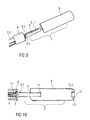
- Figures 9 and 10 show an explosion view of an alternative embodiment of a needle safety device 1 comprising an inner part 9 and an outer part 8.
- the inner part 9 and the outer part 8 comprise corresponding formed projections 12, 13 (shown in figure 10 ) to couple the inner and outer parts 8, 9 in a snap-fit connection.
- the projection 12 of the outer part 8 comprises two opposite arms 12.1, 12.2 which engage the corresponding front projection 13 of the inner part 9.
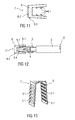
- Figure 11 shows a partial longitudinal section of an alternative embodiment of an inner part 9 of a further improved needle cap remover 7.
- the inner part 9 is formed as a hollow sheet metal part adapted to be arranged onto the rigid needle shield 5.
- the inner part 9 has a clamp shape or U-shape or the form of a sleeve or cylinder.
- the inner part 9 is made of a thin sheet metal. Furthermore, the needle cap remover 7 and the rigid needle shield 5 differs at least in the material and/or the resistance, wherein the rigid needle shield 5 is made of a rigid polypropylene material and the needle cap remover 7 is made of a thin metal sheet profile.
- the inner part 9 comprises protrusions 9.1 which extend from the inside wall into the inner hole.
- the inner part 9 comprises a plurality of inwardly directed protrusions 9.1 which are formed as hooks.
- the hooks may take a number of different forms.
- the hooks are slightly angled and inwardly protrude into the direction of the pull-off-movement of the needle cap remover 7.
- Figure 12 shows the inner part 9 formed as a sheet metal part assembled onto a rigid needle shield 5 for a needle 4 of a drug delivery device 2.
- the inwardly directed edges or protrusions 9.1 slide over the surface of the rigid needle shield 5 when the needle cap remover 7 is pushed upon the rigid needle shield 5. Pulling the needle cap remover 7 into the opposite direction and thus into the removing direction the protrusions 9.1 dig into the outer surface of the rigid needle shield 5 and thus form a positive and/or non-positive connection during removing of the rigid needle shield 5. Thus, the inner part 9 removes the rigid needle shield 5 too by further movement.
- Figure 13 shows a perspective view of a possible embodiment of an inner part 9 of a needle cap remover 7.
- the inner part 9 of the needle cap remover 7 is designed as a clamp-like sheet metal part with a plurality of inwardly directed protrusions 9.1 which are extended from each of the opposite inner surfaces in a row and in a respective distance to each other.
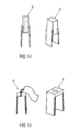
- Figure 14 shows an inner part 9 which is formed as a shrinking hose arranged as an outer wall onto the needle cap 5.1 or onto a rigid needle shield 5 encasing the needle cap 5.1 and heat shrunk onto the needle cap 5.1 or onto the encasing rigid needle shield 5.
- the shrinking hose is formed as a sleeve of high impact resistance, in particular of a thermoplastic material, wherein the coupling between the shrinking hose and the needle cap 5.1 or the encasing rigid needle shield 5 is induced by a heating during assembly. Due to the low wall thickness of the shrinking hose, the shrinking hose is arranged to the needle cap 5.1 or to the encasing rigid needle shield 5 and both together can be assembled to the drug delivery device 2.
- the needle cap remover 7 and the needle cap 5.1 or the encasing rigid needle shield 5 are arranged to each other they are heated wherein the shrinking hose shrinks so that the needle cap remover 7 and the needle cap 5.1 or the encasing rigid needle shield 5 are adhesively joined together such that, in use, if the needle cap remover 7 is moved away from the drug delivery device 2, it takes the needle cap 5.1 or the rigid needle shield 5 encasing the inner needle cap 5.1 with it and removes it from the drug delivery device 2 too and thus from the needle 4.
- Figure 15 shows an alternative embodiment of an inner part 9 of the needle cap remover 7.
- the inner part 9 is formed as a fabric tube or textile arranged onto the needle cap 5.1 or onto the rigid needle shield 5 encasing the needle cap 5.1 during assembling and mechanically shrunk onto the needle cap 5.1 or the encasing rigid needle shield 5 during removing.
- This concept allows an engaging of the needle cap remover 7 to the needle cap 5.1 or the encasing rigid needle shield 5 by a positive and/or non-positive connection, e.g. a form-fitting and/or friction connection.
- the needle cap remover 7 and the needle cap 5.1 differs at least in the material and/or the resistance too, wherein the needle cap 5.1 is made of a flexible material, e.g.
- the rigid needle shield 5 which is made of a rigid polypropylene cap.
- the inner part 9 of the needle cap remover 7 is made of a fabric or textile tube of rubber or silicon or similar materials, e.g. rubber-weave hose.
- the outer part 8 of the needle cap remover 7 of the alternative embodiments according to figures 9 to 13 may be designed as a long cap as it is described in the embodiments according to figures 1 to 2 and 7 to 8 .
- drug or “medicament”, as used herein, means a pharmaceutical formulation containing at least one pharmaceutically active compound, wherein in one embodiment the pharmaceutically active compound has a molecular weight up to 1500 Da and/or is a peptide, a proteine, a polysaccharide, a vaccine, a DNA, a RNA, an enzyme, an antibody or a fragment thereof, a hormone or an oligonucleotide, or a mixture of the above-mentioned pharmaceutically active compound, wherein in a further embodiment the pharmaceutically active compound is useful for the treatment and/or prophylaxis of diabetes mellitus or complications associated with diabetes mellitus such as diabetic retinopathy, thromboembolism disorders such as deep vein or pulmonary thromboembolism, acute coronary syndrome (ACS), angina, myocardial infarction, cancer, macular degeneration, inflammation, hay fever, atherosclerosis and/or rheumatoid arthritis, wherein in a further
- Insulin analogues are for example Gly(A21), Arg(B31), Arg(B32) human insulin; Lys(B3), Glu(B29) human insulin; Lys(B28), Pro(B29) human insulin; Asp(B28) human insulin; human insulin, wherein proline in position B28 is replaced by Asp, Lys, Leu, Val or Ala and wherein in position B29 Lys may be replaced by Pro; Ala(B26) human insulin; Des(B28-B30) human insulin; Des(B27) human insulin and Des(B30) human insulin.
- Insulin derivates are for example B29-N-myristoyl-des(B30) human insulin; B29-N-palmitoyl-des(B30) human insulin; B29-N-myristoyl human insulin; B29-N-palmitoyl human insulin; B28-N-myristoyl LysB28ProB29 human insulin; B28-N-palmitoyl-LysB28ProB29 human insulin; B30-N-myristoyl-ThrB29LysB30 human insulin; B30-N-palmitoyl- ThrB29LysB30 human insulin; B29-N-(N-palmitoyl-Y-glutamyl)-des(B30) human insulin; B29-N-(N-lithocholyl-Y-glutamyl)-des(B30) human insulin; B29-N-( ⁇ -carboxyheptadecanoyl)-des(B30) human insulin and B29-N-( ⁇ -carbox
- Exendin-4 for example means Exendin-4(1-39), a peptide of the sequence H-His-Gly-Glu-Gly-Thr-Phe-Thr-Ser-Asp-Leu-Ser-Lys-Gln-Met-Glu-Glu-Glu-Ala-Val-Arg-Leu-Phe-Ile-Glu-Trp-Leu-Lys-Asn-Gly-Gly-Pro-Ser-Ser-Gly-Ala-Pro-Pro-Pro-Ser-NH2.
- Exendin-4 derivatives are for example selected from the following list of compounds:
- Hormones are for example hypophysis hormones or hypothalamus hormones or regulatory active peptides and their antagonists as listed in Rote Liste, ed. 2008, Chapter 50, such as Gonadotropine (Follitropin, Lutropin, Choriongonadotropin, Menotropin), Somatropine (Somatropin), Desmopressin, Terlipressin, Gonadorelin, Triptorelin, Leuprorelin, Buserelin, Nafarelin, Goserelin.
- Gonadotropine Follitropin, Lutropin, Choriongonadotropin, Menotropin
- Somatropine Somatropin
- Desmopressin Terlipressin
- Gonadorelin Triptorelin
- Leuprorelin Buserelin
- Nafarelin Goserelin.
- a polysaccharide is for example a glucosaminoglycane, a hyaluronic acid, a heparin, a low molecular weight heparin or an ultra low molecular weight heparin or a derivative thereof, or a sulphated, e.g. a poly-sulphated form of the above-mentioned polysaccharides, and/or a pharmaceutically acceptable salt thereof.
- An example of a pharmaceutically acceptable salt of a poly-sulphated low molecular weight heparin is enoxaparin sodium.
- Antibodies are globular plasma proteins ( ⁇ 150 kDa) that are also known as immunoglobulins which share a basic structure. As they have sugar chains added to amino acid residues, they are glycoproteins.
- the basic functional unit of each antibody is an immunoglobulin (Ig) monomer (containing only one Ig unit); secreted antibodies can also be dimeric with two Ig units as with IgA, tetrameric with four Ig units like teleost fish IgM, or pentameric with five Ig units, like mammalian IgM.
- Ig immunoglobulin
- the Ig monomer is a "Y"-shaped molecule that consists of four polypeptide chains; two identical heavy chains and two identical light chains connected by disulfide bonds between cysteine residues. Each heavy chain is about 440 amino acids long; each light chain is about 220 amino acids long. Heavy and light chains each contain intrachain disulfide bonds which stabilize their folding. Each chain is composed of structural domains called Ig domains. These domains contain about 70-110 amino acids and are classified into different categories (for example, variable or V, and constant or C) according to their size and function. They have a characteristic immunoglobulin fold in which two ⁇ sheets create a "sandwich" shape, held together by interactions between conserved cysteines and other charged amino acids.
- Ig heavy chain There are five types of mammalian Ig heavy chain denoted by ⁇ , ⁇ , ⁇ , ⁇ , and ⁇ .
- the type of heavy chain present defines the isotype of antibody; these chains are found in IgA, IgD, IgE, IgG, and IgM antibodies, respectively.
- Distinct heavy chains differ in size and composition; ⁇ and ⁇ contain approximately 450 amino acids and ⁇ approximately 500 amino acids, while ⁇ and ⁇ have approximately 550 amino acids.
- Each heavy chain has two regions, the constant region (C H ) and the variable region (V H ).
- the constant region is essentially identical in all antibodies of the same isotype, but differs in antibodies of different isotypes.
- Heavy chains ⁇ , ⁇ and ⁇ have a constant region composed of three tandem Ig domains, and a hinge region for added flexibility; heavy chains ⁇ and ⁇ have a constant region composed of four immunoglobulin domains.
- the variable region of the heavy chain differs in antibodies produced by different B cells, but is the same for all antibodies produced by a single B cell or B cell clone.
- the variable region of each heavy chain is approximately 110 amino acids long and is composed of a single Ig domain.
- a light chain has two successive domains: one constant domain (CL) and one variable domain (VL).
- CL constant domain
- VL variable domain
- the approximate length of a light chain is 211 to 217 amino acids.
- Each antibody contains two light chains that are always identical; only one type of light chain, ⁇ or ⁇ , is present per antibody in mammals.
- variable (V) regions are responsible for binding to the antigen, i.e. for its antigen specificity.
- VL variable light
- VH variable heavy chain
- CDRs Complementarity Determining Regions
- an "antibody fragment” contains at least one antigen binding fragment as defined above, and exhibits essentially the same function and specificity as the complete antibody of which the fragment is derived from.
- Limited proteolytic digestion with papain cleaves the Ig prototype into three fragments. Two identical amino terminal fragments, each containing one entire L chain and about half an H chain, are the antigen binding fragments (Fab).
- the Fc contains carbohydrates, complement-binding, and FcR-binding sites.
- F(ab')2 is divalent for antigen binding.
- the disulfide bond of F(ab')2 may be cleaved in order to obtain Fab'.
- the variable regions of the heavy and light chains can be fused together to form a single chain variable fragment (scFv).
- Pharmaceutically acceptable salts are for example acid addition salts and basic salts.
- Acid addition salts are e.g. HCl or HBr salts.
- Basic salts are e.g. salts having a cation selected from alkali or alkaline, e.g. Na+, or K+, or Ca2+, or an ammonium ion N+(R1)(R2)(R3)(R4), wherein R1 to R4 independently of each other mean: hydrogen, an optionally substituted C1-C6-alkyl group, an optionally substituted C2-C6-alkenyl group, an optionally substituted C6-C10-aryl group, or an optionally substituted C6-C10-heteroaryl group.
- solvates are for example hydrates.
Landscapes
- Health & Medical Sciences (AREA)
- Engineering & Computer Science (AREA)
- Hematology (AREA)
- Anesthesiology (AREA)
- Biomedical Technology (AREA)
- Heart & Thoracic Surgery (AREA)
- Vascular Medicine (AREA)
- Life Sciences & Earth Sciences (AREA)
- Animal Behavior & Ethology (AREA)
- General Health & Medical Sciences (AREA)
- Public Health (AREA)
- Veterinary Medicine (AREA)
- Environmental & Geological Engineering (AREA)
- Infusion, Injection, And Reservoir Apparatuses (AREA)
Abstract
The invention refers to a drug delivery device (2) comprising a housing (2.1) capable of receiving and containing a container (syringe 3) and a needle safety device (1). The needle safety device (1) comprises a needle cap (5.1) arranged to cover and protect a needle (4), a needle shield (6) relatively movable with respect to the housing (2.1) to cover and protect the needle (4) and a needle cap remover (7). The needle cap remover (7) has an outer part (8) adapted to be arranged to the housing (2.1) and to cover the needle shield (6) and partly the housing (2.1) and an inner part (9) adapted to be arranged to the needle cap (5.1).
Description
- The invention relates to a drug delivery device comprising such a needle safety device.
- Many drug delivery devices of the prior art, such as auto-injectors, syringes, have been developed for self-administration of the drug.
- To protect the needle of the drug delivery device from damage or to protect people from needle-prick injuries before using of the device, the needle of the drug delivery device is covered by a protective needle cap of a flexible material which can be encased by a rigid, in particular a plastic needle shield, the so-called rigid needle shield (shortly named RNS).
- In order to prepare the drug delivery device for delivering a dose the protective needle cap has to be removed from the needle. This may be done by gripping the protective needle cap and pulling it away from the needle. This will usually result in an exposed needle which is undesirable in terms of needle safety or for person with a needle phobia. In order to solve that problem the needle of the drug delivery device could be covered by a needle shield or shroud in a manner to hide the needle when the protective needle cap is removed.
- It is an object of the present invention to provide a drug delivery device that reduces the risk of needle-prick injuries and needle damages in particular before using the device and which is simple to use, manufacture and assembling.
- The object is achieved by a drug delivery device according to
claim 1. - Preferred embodiments of the invention are given in the dependent claims.
- According to the invention, a drug delivery device comprises a housing capable of receiving and containing a container and a needle safety device which comprises a needle cap or a rigid needle shield encasing the needle cap arranged to cover and protect a needle, a needle shield relatively movable with respect to the housing to cover and protect the needle and a needle cap remover. The needle cap remover has an outer part adapted to be arranged to the housing and to cover the needle shield and partly the housing and an inner part adapted to be arranged to the needle cap or to the rigid needle shield encasing the needle cap.
- In the context of this specification, the term "back" or "proximal" end of a component or of a device refers to the end closest to the user's hand or furthest away from the delivery or injection site and the term "front" or "distal" end of a component or device refers to the end furthest from the user's hand or closest to the delivery or injection site.
- In a possible embodiment, the needle cap remover, in particular the outer part and the inner part are formed as a one part remover. Alternatively, the needle cap remover is formed as a multiple-part remover with a separate inner part and a separate outer part which are loosely coupled to each other, in particular which are relatively movable to each other in a given distance to compensate length tolerances.
- The arrangement and the respective size of the needle cap remover to cover the needle shield fully and the housing of the drug delivery device partly so that the outer part of the needle cap remover forms a cap which slips over the needle shield and the front or distal end of the housing prevents an unintended, in particular a too early movement of the needle shield. Furthermore, the integrated design of the needle cap remover with an inner part which forms the needle cap remover and with an outer part which forms an outer gripping cap provides a rigid design with optimized connections with the needle cap and safe covering of the needle. In particular, only an axial force exerts to the needle cap, thus ensures that the needle will be contaminate-free and thus keep sterile. In a possible embodiment, the needle cap remover has at least one overlapping portion between the needle cap remover and the housing and/or the needle cap remover and the needle cap. The at least one overlapping portion provides a simple compensation of occurred length tolerances of the components of the drug delivery device, in particular of the needle safety device. In particular, occurring length tolerances of the device components are compensated by axial relocatability between the needle cap and the needle cap remover.
- According to an embodiment of the invention, a second overlapping portion is provided between the outer part of the needle cap remover and the housing to compensate axial clearance between the needle cap remover and the housing. In particular, in this second overlapping portion occurring length tolerances of the respective components can be compensated by a given maximal axial relocatability between the needle cap remover and the housing.
- According to an additional feature of the invention, an inner surface of the outer part and an outer surface of the housing in the second overlapping portion are correspondingly formed. In particular, the inner surface and the outer surface are profiled e.g. with grooves, notches, recesses, ridges and/or ribs to provide an adjustable snap-fit-connection and/or positive locking connection and/or form-fitting connection.
- Additionally or alternatively, a first overlapping portion is provided between the inner part of the needle cap remover and the outer part of the needle cap remover to compensate axial clearance between the needle cap remover and the needle cap or the rigid needle shield encasing the needle cap. In particular, in this first overlapping portion occurring length tolerances of the respective components can be compensated by a given maximal axial relocatability between the separate inner part and the outer part of the needle cap remover, and thus between the needle cap remover and the needle cap or the rigid needle shield encasing the needle cap.
- In other words: The multiple-part design of the needle cap remover comprising the inner part and the outer part which are coupled to each other by corresponding projections allows a limited setting range of the needle cap remover with respect to the needle cap. In a possible embodiment, the outer part of the needle cap remover is designed as an outer cap which covers and protects the inner needle shield and thus prevents an unintended, in particular a too early movement of the needle shield.
- The outer part comprises a front end having an opening which at its edge exhibits a projection directed inwards adapted to catch a front projection of the inner part so as to couple the outer part and the inner part within the given first overlapping portion. The inner part comprises a back end having a grip member adapted to grip a back end of the needle cap so as to couple the needle cap remover and the needle cap. In a possible embodiment, the grip member is formed as locking hooks.
- In an exemplary embodiment, the projection of the outer part is formed as at least two opposite arms which ends are angled. In particular, the ends of the opposite arms could be angled away from each other or otherwise to engage the corresponding front projection of the inner part. Depending on the material of the inner and outer part of the needle cap remover, at least one of the parts, in particular the opposite arms or the front projection are flexible, e.g. are made of a flexible material or soft plastic. Due to a flexible design of the angled ends, the flexible arms of the outer part could be linked to the inner part in such a manner that they are pivoted or swiveled to approach each other so that they are carried over the rigid front projection of the inner part when the outer part is assembled onto or into the inner part. Otherwise, the flexible front projection may be pivoted or swiveled away from each other by the rigid arms of the outer part when the outer part is assembled to the inner part, e.g. onto or into the inner part. After assembling of the outer and inner parts, the front projection of the inner part and the projection of the outer part are correspondingly inclined to each other in such a manner that they are coupled to each other to allow a common axial movement after assembling.
- In a possible embodiment, the front projection of the inner part is correspondingly formed to the projection of the outer part. In particular the front projection of the inner part is formed as at least two protruding tabs. The protruding tabs are protruded from the inner surface of the inner part and are directed inwards in an angle to be gripped by the also angled ends of the arms of the outer part. During assembling of the outer part onto or into the inner part, the angled ends of the arms and the angled protruding tabs of the front projection are coupled and engaged by a positive-locking connection and/or form-fitting connection, e.g. snap-fit-connection or latching connection.
- In a further embodiment, the front projection of the inner part is formed as flexible legs or a stem with flexible legs which protrude from the front end of the inner part and directed inwards through the opening of the outer part.
- According to another embodiment of the invention, the grip member of the inner part is formed as a back projection of the inner part. The back projection bents into the inner part to engage the back end of the needle cap by a positive-locking connection and/or form-fitting connection. In particular, the back projection is formed as at least two legs directed inwards to engage the back end of the needle cap or the rigid needle shield encasing the needle cap.
- According to an alternative embodiment, the grip member of the inner part of the needle cap remover may be formed with a profiled surface adapted to grip lateral surfaces of the needle cap or the rigid needle shield encasing the needle cap e.g. by friction connection and/or positive-locking connection and/or form-fitting connection. In particular, the inner surface of the inner part is roughened or lightly ribbed or grooved or coated by a soft coating material.
- Alternatively or additionally, the needle cap or the encasing rigid needle shield has an outer surface comprising grip elements adapted to be gripped by the grip member of the inner part of the needle cap remover e.g. by positive-locking connection and/or form-fitting connection and/or friction connection. In particular, the grip elements of the needle cap or encasing the rigid needle shield may be formed as a profiled outer surface, e.g. as ribs, hooks, domes, grooves and/or protruding pegs, arms. The coupling between the inner part of the needle cap remover and the needle cap or the rigid needle shield encasing the needle cap is designed in such a manner that after assembling during an axial movement of the needle cap remover the needle cap or the rigid needle shield encasing the needle cap is removed from the needle together with the needle cap remover.
- In yet a further embodiment, the inner part of the needle cap remover is inserted into an opening of the needle shield and is also inserted in this opening between the needle cap or the rigid needle shield encasing the needle cap and a spring which engages on one end at the housing and on the other end at the needle shield. The opening or the hole in the needle shield has an appropriate width to allow the insertion of the inner part of the needle cap remover.
- Further scope of applicability of the present invention will become apparent from the detailed description given hereinafter. However, it should be understood that the detailed description and specific examples, while indicating preferred embodiments of the invention, are given by way of illustration only, since various changes and modifications within the spirit and scope of the invention will become apparent to those skilled in the art from this detailed description.
- The present invention will become more fully understood from the detailed description given herein below and the accompanying drawings which are given by way of illustration only, and thus, are not limitive of the present invention, and wherein:
- Figure 1
- shows a partial longitudinal cross section of an exemplary embodiment of a front part of a drug delivery device with a needle safety device in a protection position,
- Figure 2
- shows a partial longitudinal cross section of an exemplary embodiment of a front part of a drug delivery device with a needle safety device in an intermediate position during removing of a needle cap,
- Figure 3
- shows a perspective view of an exemplary embodiment of a needle cap remover,
- Figure 4
- shows an enlarged view of the connection between a needle cap remover and a needle cap,
- Figure 5
- shows a perspective view of another exemplary embodiment of a needle safety device,
- Figure 6
- shows an enlarged view of another exemplary connection between a needle cap remover and a needle cap,
- Figures 7 and 8
- show partial longitudinal cross sections of exemplary embodiments of a front part of a drug delivery device with a needle safety device in a protection position.
- Figures 9 and 10
- show an explosion view of a needle safety device of a drug delivery device
- Figure 11
- shows a partial longitudinal section of an embodiment of an alternative inner part of a needle cap remover,
- Figure 12
- shows the inner part of the needle cap remover according to
figure 9 assembled to a needle cap of a drug delivery device in a longitudinal section, - Figure 13
- shows a perspective view of an embodiment of a clamp-like inner part of a needle cap remover, and
- Figures 14 and 15
- show alternative embodiments of the inner part of the needle cap remover.
- Corresponding parts are marked with the same reference symbols in all figures.
-
Figure 1 shows one embodiment of the present invention in a partial longitudinal cross section of aneedle safety device 1 for adrug delivery device 2. - The
drug delivery device 2 is apre-filled syringe 3 having aneedle 4. Theneedle 4 may be fixed to the distal end of thesyringe 3 or removable therefrom, as a matter of design choice. Thesyringe 3 is hold in a housing 2.1 of thedrug delivery device 2. Alternatively, the drug delivery device could be an auto-injector with a container, an injection pen or a syringe to be filled or another medicament container or any other application with comparable functional principle. The housing 2.1 may be designed as a one part or multiple part housing capable of receiving and containing the container, in the embodiment thesyringe 3. In the shown embodiment the housing 2.1 comprises a front part 2.1.1 and a back part 2.1.2. - The
needle safety device 1 comprises arigid needle shield 5 encasing a needle cap 5.1, aneedle shield 6 and aneedle cap remover 7 which are adapted to be connected to each other by friction connection and/or positive locking connection and/or form-fitting connection. As it can be seen, theneedle shield 6 is being mounted on the housing 2.1 of thedrug delivery device 2 in a movable manner. In particular, theneedle shield 6 is movably mounted on the front part 2.1.1 of the housing 2.1. - The needle cap 5.1 encased by the
rigid needle shield 5 is being mounted on theneedle 4 in a separable manner. Theneedle cap remover 7 is being mounted on therigid needle shield 5 in a secured manner and on the housing 2.1, in particular on the front part 2.1.1, in a separable manner. - The
rigid needle shield 5 is designed as a protective needle shield so called as a rigid needle shield (shortly named RNS) which covers theneedle 4 before use to protect it against damages during transport or travel and to stay it sterile during the assembly process. In the shown embodiment therigid needle shield 5 encases the needle cap 5.1 which is made of a flexible material e.g. of rubber or silicon. - In an alternative, not shown embodiment, the
needle safety device 1 comprises only the needle cap 5.1 without the rigid needle shield so that theneedle cap remover 7 is directly arranged onto the needle cap 5.1. The function and the arrangement of theneedle cap remover 7 directly onto the needle cap 5.1 or onto therigid needle shield 5 encasing the needle cap 5.1 are identical and do not differ from each other. Thus, the following description regarding to a needle cap remover arranged onto a rigid needle shield encasing a needle cap also applies to a needle cap remover directly arranged onto the needle cap without an encasing. - The
needle cap remover 7 is formed as an integrated unit with aninner part 9 and anouter part 8. Theinner part 9 is adapted to be arranged to therigid needle shield 5 and forms an inner gripper for therigid needle shield 5. Theouter part 8 is adapted to be arranged to the housing 2.1 and forms an outer gripping surface for a user of the device. The invention prevents a misuse or unintended activation and optimizes the connection between therigid needle shield 5 and theneedle cap remover 7. - As not shown in the longitudinal cross sections of the
needle safety device 1, the components, in particular theneedle cap remover 7 with theinner part 9 and theouter part 8 as well as the needle cap 5.1, have tubular or cylindrical shapes. They may be having different shapes and may have oval or polygonal shapes in cross section. - The
needle cap remover 7 has a respective size and is arranged to thedrug delivery device 2 and therigid needle shield 5 in such a manner that it cover theneedle shield 6 fully and the housing 2.1 in part, in particular only the front part 2.1.1. Theouter part 8 of theneedle cap remover 7 forms an outer gripping surface in form of a cap which slips over theneedle shield 6 and the front part 2.1.1 of the housing 2.1 during assembling so that an early movement of theneedle shield 6 is prevented. - In detail, the needle cap 5.1 is arranged onto a needle hub 4.1 to directly cover and protect the
needle 4. The needle cap 5.1 may be connected to a needle hub 4.1 of theneedle 4 by means of a friction connection and/or positive locking connection. The needle cap 5.1 is preferably of a resilient material, especially of a soft elastomer, for example rubber or a thermoplastic elastomer (TPE). Therigid needle shield 5 encasing the needle cap 5.1 is preferably of a rigid material and is formed as a protective needle shield, e.g. as a rigid needle shield. - The
needle shield 6 covers and protects theneedle 4 before, during and after use and in particular also after removing of therigid needle shield 5 and the encased needle cap 5.1. Theneedle shield 6 is movably arranged with respect to the housing 2.1 of thedrug delivery device 2. In the shown embodiment, theneedle shield 6 is provided at the distal or front end of the housing 2.1. In particular, theneedle shield 6 is arranged onto the housing 2.1. Alternatively, theneedle shield 6 could be arranged into the housing 2.1. - As shown in
figure 1 , theneedle shield 6 is in the advanced or extended position in which theneedle 4 is covered. Theneedle shield 6 is secured in the advanced position by aspring element 17 which bears at one end on theneedle shield 6 and at the other end on the housing 2.1. In this advanced position before use, theneedle shield 6 is hold by a positive connection and/or a friction connection and/or a form-fitting connection, e.g. a snap-fit connection 6.1. During use, theneedle shield 6 is movable from the advanced position to a retracted position wherein thespring element 17 is tensioned (not shown). After use, theneedle shield 6 is movable back to the advanced position in which theneedle shield 6 is securely fixed with respect to the housing 2.1. - The
needle shield 6 comprises an opening 6.2 through which theneedle cap remover 7 is inserted. In particular, theinner part 9 of theneedle cap remover 7 is inserted in this opening 6.2 between therigid needle shield 5 and thespring 17. The opening 6.2 or the hole in theneedle shield 6 has an appropriate width to allow the insertion of theinner part 9. In respect to this design, theneedle cap remover 7 might be assembled to the device before or after theneedle shield 6. - The
needle cap remover 7 comprises at least theouter part 8 and theinner part 9. Theouter part 8 is adapted to be arranged at the housing 2.1 and is formed as an outer gripping surface. Preferably, theouter part 8 is releasably coupled to the housing 2.1 by a friction connection and/or a form-fitting connection. In detail, theouter part 8 of theneedle cap remover 7 is designed as an outer gripping cap which covers and protects theinner needle shield 6 and thus prevents an unintended, in particular a too early movement of theneedle shield 6. - The
inner part 9 is adapted to carry therigid needle shield 5 by a friction connection and/or a positive locking connection wherein therigid needle shield 5 forms the so-called protective needle shield or rigid needle shield (shortly named RNS) of theneedle safety device 1. - The
outer part 8 comprises afront end 10 having anopening 11 which at its edge exhibits aprojection 12 directed inwards. The inwardly directedprojection 12 forms theinner part 9 of theneedle cap remover 7. - Depending on the design of the
needle cap remover 7, theinner part 9 and theouter part 8 may be formed as an integrated unit shown in embodiments according tofigures 1 to 6 . Alternatively theinner part 9 and theouter part 8 may be formed as separate but securely and non-releasably coupled parts, shown in embodiments according tofigures 7 and 8 . - Due to the coupling of the
outer part 8 with theinner part 9 and theinner part 9 with therigid needle shield 5, the needle cap 5.1 encased by rigid theneedle shield 5 is removed from theneedle 4 when theouter part 8 is removed from thedrug delivery device 2. - The
inner part 9 comprises aback end 14. Theback end 14 has agrip member 15 adapted to grip aback end 16 of therigid needle shield 5 so as to couple theneedle cap remover 7 to therigid needle shield 5. - The
grip member 15 is designed as looking hooks 15.1, 15.2 which cooperate with a complementary locking element 16.1, e.g. recess or groove, arranged at theback end 16 of therigid needle shield 5. The locking hooks 15.1, 15.2 engage theback end 16 of therigid needle shield 5 by a positive-locking connection and/or form-fitting connection. -
Figure 2 shows thedrug delivery device 2 with thesafety needle device 1 in an intermediate position in which theneedle cap remover 7 is slightly removed from the housing 2.1 into direction D. Due to the coupling of theneedle cap remover 7 and therigid needle shield 5 as well as to the encasing and coupling of the needle cap 5.1 by therigid needle shield 5, therigid needle shield 5 together with the needle cap 5.1 is correspondingly removed from theneedle 4. -
Figure 3 shows a partial perspective view of an exemplary embodiment of aneedle cap remover 7, whereinfigure 4 shows an enlarged view of the connection between theneedle cap remover 7 and therigid needle shield 5.Figure 3 shows the needle cap 5.1 andinner part 9 of theneedle cap remover 7. Theneedle shield 6 and theouter part 8 are not shown. - The resilient needle cap 5.1 is internally arranged in the
rigid needle shield 5 shown infigure 4 . - The
inner part 9 of theneedle cap remover 7 is formed as a cap remover to remove therigid needle shield 5 together with the encased needle cap 5.1 from theneedle 4 before use. To securely couple theneedle cap remover 7 to therigid needle shield 5, theinner part 9 has a tubular form with pairs of elongated windows 9.1.1 and 9.1.2 so that at least the circumferential edges of the windows 9.1.1 are formed as flexible arms. At the back end 9.2 of each window 9.1.1, the respective edges 9.2 equipped with hooks 9.3 engaging theback end 16 of therigid needle shield 5. When theneedle cap remover 7 is inserted into the opening 6.2 of theneedle shield 6, the hooks 9.3 at the flexible arms or windows 9.1.1 being movable along the longitudinal axis of therigid needle shield 5 into the opening 6.2 between therigid needle shield 5 and the spring element 17 (not shown infigure 3 ) so that the windows 9.1.1 and thus the hooks 9.3 are deformed, in particular spread outwards, and after having passed theback end 16 of therigid needle shield 5 the hooks 9.3 are spread back inwardly and securely engaged theback end 16 in a snap-fit connection or form-fitting connection. -
Figures 5 and 6 show a perspective view of another exemplary embodiment of aneedle safety device 1 with an enlarged view of another exemplary connection between aneedle cap remover 7 andrigid needle shield 5. - The
inner part 9 of theneedle cap remover 7 has a tubular form with two opposite elongated windows 9.1.1. Theinner part 9 is rigid. For an easy assembling of theneedle cap remover 7 into the opening 6.2 of theneedle shield 6 to grip therigid needle shield 5, at the back end 9.2 of each window 9.1.1 at least one flexible leg 9.4 extends inwardly into theinner part 9 to engage theback end 16 of therigid needle shield 5, thereby forming a snap-fit means. - When the
needle cap remover 7 is inserted into the opening 6.2 of theneedle shield 6, the flexible legs 9.4 being movable along the longitudinal axis of therigid needle shield 5 into the opening 6.2 between therigid needle shield 5 and the spring element 17 (not shown infigure 3 ) so that the legs 9.4 are deformed, in particular spread outwards, and after having passed theback end 16 of therigid needle shield 5 the legs 9.4 are spread back inwardly and securely engaged theback end 16 in a snap-fit connection, a positive locking connection or form-fitting connection. -
Figures 7 and 8 show partial longitudinal cross sections of exemplary embodiments of a front part of adrug delivery device 2 with aneedle safety device 1 in a protection position. The difference between thefigures 7 and 8 is that infigure 7 theouter body 8 of theneedle cap remover 7 is coupled to afront projection 13 of theinner part 9 with a given first overlapping portion F1. - According to
figure 8 - a further embodiment of the invention -, theouter part 8 of theneedle cap remover 7 and the back part 2.1.2 of the housing 2.1 are overlapped in a given second overlapping portion F2. - Occurring length tolerances of the housing 2.1 and the
needle cap remover 7 may be compensated by an axial clearance of an axial relocatability between theneedle cap remover 7 and the housing 2.1 within the given first overlapping portion F1 or the given second overlapping portion F2. - According to the concept of compensation of length tolerances in
figure 7 , theneedle cap remover 7 comprises theouter part 8 and theinner part 9 which are non-releasable coupled with the first overlapping portion F1. The inwardly directedprojection 12 is adapted to catch afront projection 13 of theinner part 9 so as to non-releasable couple theouter part 8 to theinner part 9 by a positive locking connection and/or a form-fitting connection. - The multiple-part design of the
needle cap remover 7 offigure 7 with the separateinner part 9 and the separateouter part 8 which are coupled to each other by correspondingprojections needle cap remover 7 by the first overlapping portion F1. Occurring length tolerances of needle cap 5.1 and theneedle cap remover 7 can be compensated by an axial relocatability between the needle cap 5.1 and theneedle cap remover 7 within the first overlapping portion F1. - In an exemplary embodiment, the
projection 12 of theouter part 8 is designed as at least two opposite arms 12.1, 12.2 which free ends are angled. In particular, the ends of the opposite arms 12.1, 12.2 are angled to each other or alternatively away from each other to engage the correspondingfront projection 13 of theinner part 9 e.g. in a clip connection, snap-fit connection, form-fitting connection and/or positive locking connection. Depending on the material of the inner andouter part needle cap remover 7, at least one of the parts, in particular the opposite arms 12.1, 12.2 of theouter part 8 are flexible, e.g. are made of a flexible or soft plastic material. Alternatively, the opposite arms 12.1, 12.2 are rigid and thefront projection 13 is made of a flexible material. - Due to the flexible design of the arms 12.1, 12.2 with the angled ends, the flexible arms 12.1, 12.2 could be pivoted or swiveled away from each other so that they are carried over the
rigid front projection 13 of theinner part 9 during assembling of theouter part 8 to theinner part 9. - Otherwise, the
flexible front projection 13 may be pivoted or swiveled so that the hooked ends of thefront projection 13 come closer. After assembling of the outer andinner parts front projection 13 of theinner part 9 and theprojection 12 of theouter part 8 are correspondingly inclined to each other in such a manner that they are coupled to each other to allow a common axial movement and in particular an axial relocatability between therigid needle shield 5 and theneedle cap remover 7 within the first overlapping portion F1 and thus within a setting range. - As it is shown in
figure 7 , thefront projection 13 of theinner part 9 is correspondingly formed to theprojection 12 of theouter part 8. In particular thefront projection 13 is formed as at least two protruding tabs 13.1, 13.2. The protruding tabs 13.1, 13.2 are protruded from the inner surface of theinner part 9 and are directed inwards in an angle to be gripped by the also angled ends of the arms 12.1, 12.2 of theouter part 8. - After assembling of the
needle cap remover 7, the angled ends of the arms 12.1, 12.2 and the angled protruding tabs 13.1, 13.2 are coupled and securely engaged, wherein the tabs 13.1, 13.2 define a stop on which the arms 12.1, 12.2 come in abutment in such a manner that when theouter part 8 is gripped and removed from theneedle shield 6 theinner part 9 moves too to remove therigid needle shield 5 and the encased needle cap 5.1 from theneedle 4. In particular, the arms 12.1, 12.2 and the protruding tabs 13.1, 13.2 are securely engaged by a positive-locking connection and/or form-fitting connection, e.g. snap-fit-connection or latching connection. -
Figure 8 shows that the inner surface of theouter part 8 and the outer surface of the housing 2.1 in the second overlapping portion F2 are correspondingly formed, in particular profiled, e.g. with grooves, ribs, forming press-fit means to provide an adjustable and releasable snap-fit-connection. - The
inner part 9 and theouter part 8 are coupled to each other without any compensation of length tolerances. For example theinner part 9 and theouter part 8 are fixed or are formed as an integrated part. - According to the embodiment of
figure 8 , theneedle cap remover 7, in particular theouter part 8 and theinner part 9 are formed as a one part remover. - In summary, depend on the design of the
drug delivery device 2 with at least one or two overlapping portions F1, F2 occurring length tolerances may be compensated by axial relocatability of the respective components between the housing 2.1 and theneedle cap remover 7 as well as between theneedle cap remover 7 and therigid needle shield 5. - The described different embodiments of a clip-like
needle cap remover 7 can be used at smart safety syringe systems. The invention allows that the assembly force to the rigid needle shield 5 (= RNS) is only induced in axial direction. Further, due to the enlarged and cap-likeouter part 8 of theneedle cap remover 7, which fully cover theneedle shield 6, an unintended, in particular a too early movement of theneedle shield 6 is prevented. -
Figures 9 and 10 show an explosion view of an alternative embodiment of aneedle safety device 1 comprising aninner part 9 and anouter part 8. Theinner part 9 and theouter part 8 comprise corresponding formedprojections 12, 13 (shown infigure 10 ) to couple the inner andouter parts projection 12 of theouter part 8 comprises two opposite arms 12.1, 12.2 which engage the correspondingfront projection 13 of theinner part 9. -
Figure 11 shows a partial longitudinal section of an alternative embodiment of aninner part 9 of a further improvedneedle cap remover 7. Theinner part 9 is formed as a hollow sheet metal part adapted to be arranged onto therigid needle shield 5. Theinner part 9 has a clamp shape or U-shape or the form of a sleeve or cylinder. - The
inner part 9 is made of a thin sheet metal. Furthermore, theneedle cap remover 7 and therigid needle shield 5 differs at least in the material and/or the resistance, wherein therigid needle shield 5 is made of a rigid polypropylene material and theneedle cap remover 7 is made of a thin metal sheet profile. - Furthermore, the
inner part 9 comprises protrusions 9.1 which extend from the inside wall into the inner hole. Preferably, theinner part 9 comprises a plurality of inwardly directed protrusions 9.1 which are formed as hooks. The hooks may take a number of different forms. Preferably, the hooks are slightly angled and inwardly protrude into the direction of the pull-off-movement of theneedle cap remover 7. -
Figure 12 shows theinner part 9 formed as a sheet metal part assembled onto arigid needle shield 5 for aneedle 4 of adrug delivery device 2. - During assembling, the inwardly directed edges or protrusions 9.1 slide over the surface of the
rigid needle shield 5 when theneedle cap remover 7 is pushed upon therigid needle shield 5. Pulling theneedle cap remover 7 into the opposite direction and thus into the removing direction the protrusions 9.1 dig into the outer surface of therigid needle shield 5 and thus form a positive and/or non-positive connection during removing of therigid needle shield 5. Thus, theinner part 9 removes therigid needle shield 5 too by further movement. -
Figure 13 shows a perspective view of a possible embodiment of aninner part 9 of aneedle cap remover 7. Theinner part 9 of theneedle cap remover 7 is designed as a clamp-like sheet metal part with a plurality of inwardly directed protrusions 9.1 which are extended from each of the opposite inner surfaces in a row and in a respective distance to each other. - Further alternative embodiments of the inner part of the needle cap remover are shown in
figures 14 and 15 . -
Figure 14 shows aninner part 9 which is formed as a shrinking hose arranged as an outer wall onto the needle cap 5.1 or onto arigid needle shield 5 encasing the needle cap 5.1 and heat shrunk onto the needle cap 5.1 or onto the encasingrigid needle shield 5. - In an exemplary embodiment, the shrinking hose is formed as a sleeve of high impact resistance, in particular of a thermoplastic material, wherein the coupling between the shrinking hose and the needle cap 5.1 or the encasing
rigid needle shield 5 is induced by a heating during assembly. Due to the low wall thickness of the shrinking hose, the shrinking hose is arranged to the needle cap 5.1 or to the encasingrigid needle shield 5 and both together can be assembled to thedrug delivery device 2. After theneedle cap remover 7 and the needle cap 5.1 or the encasingrigid needle shield 5 are arranged to each other they are heated wherein the shrinking hose shrinks so that theneedle cap remover 7 and the needle cap 5.1 or the encasingrigid needle shield 5 are adhesively joined together such that, in use, if theneedle cap remover 7 is moved away from thedrug delivery device 2, it takes the needle cap 5.1 or therigid needle shield 5 encasing the inner needle cap 5.1 with it and removes it from thedrug delivery device 2 too and thus from theneedle 4. -
Figure 15 shows an alternative embodiment of aninner part 9 of theneedle cap remover 7. Theinner part 9 is formed as a fabric tube or textile arranged onto the needle cap 5.1 or onto therigid needle shield 5 encasing the needle cap 5.1 during assembling and mechanically shrunk onto the needle cap 5.1 or the encasingrigid needle shield 5 during removing. This concept allows an engaging of theneedle cap remover 7 to the needle cap 5.1 or the encasingrigid needle shield 5 by a positive and/or non-positive connection, e.g. a form-fitting and/or friction connection. In particular, theneedle cap remover 7 and the needle cap 5.1 differs at least in the material and/or the resistance too, wherein the needle cap 5.1 is made of a flexible material, e.g. rubber, and may be encased by therigid needle shield 5 which is made of a rigid polypropylene cap. Theinner part 9 of theneedle cap remover 7 is made of a fabric or textile tube of rubber or silicon or similar materials, e.g. rubber-weave hose. - The
outer part 8 of theneedle cap remover 7 of the alternative embodiments according tofigures 9 to 13 may be designed as a long cap as it is described in the embodiments according tofigures 1 to 2 and7 to 8 . - The term "drug" or "medicament", as used herein, means a pharmaceutical formulation containing at least one pharmaceutically active compound,
wherein in one embodiment the pharmaceutically active compound has a molecular weight up to 1500 Da and/or is a peptide, a proteine, a polysaccharide, a vaccine, a DNA, a RNA, an enzyme, an antibody or a fragment thereof, a hormone or an oligonucleotide, or a mixture of the above-mentioned pharmaceutically active compound,
wherein in a further embodiment the pharmaceutically active compound is useful for the treatment and/or prophylaxis of diabetes mellitus or complications associated with diabetes mellitus such as diabetic retinopathy, thromboembolism disorders such as deep vein or pulmonary thromboembolism, acute coronary syndrome (ACS), angina, myocardial infarction, cancer, macular degeneration, inflammation, hay fever, atherosclerosis and/or rheumatoid arthritis,
wherein in a further embodiment the pharmaceutically active compound comprises at least one peptide for the treatment and/or prophylaxis of diabetes mellitus or complications associated with diabetes mellitus such as diabetic retinopathy,
wherein in a further embodiment the pharmaceutically active compound comprises at least one human insulin or a human insulin analogue or derivative, glucagon-like peptide (GLP-1) or an analogue or derivative thereof, or exendin-3 or exendin-4 or an analogue or derivative of exendin-3 or exendin-4. - Insulin analogues are for example Gly(A21), Arg(B31), Arg(B32) human insulin; Lys(B3), Glu(B29) human insulin; Lys(B28), Pro(B29) human insulin; Asp(B28) human insulin; human insulin, wherein proline in position B28 is replaced by Asp, Lys, Leu, Val or Ala and wherein in position B29 Lys may be replaced by Pro; Ala(B26) human insulin; Des(B28-B30) human insulin; Des(B27) human insulin and Des(B30) human insulin.
- Insulin derivates are for example B29-N-myristoyl-des(B30) human insulin; B29-N-palmitoyl-des(B30) human insulin; B29-N-myristoyl human insulin; B29-N-palmitoyl human insulin; B28-N-myristoyl LysB28ProB29 human insulin; B28-N-palmitoyl-LysB28ProB29 human insulin; B30-N-myristoyl-ThrB29LysB30 human insulin; B30-N-palmitoyl- ThrB29LysB30 human insulin; B29-N-(N-palmitoyl-Y-glutamyl)-des(B30) human insulin; B29-N-(N-lithocholyl-Y-glutamyl)-des(B30) human insulin; B29-N-(ω-carboxyheptadecanoyl)-des(B30) human insulin and B29-N-(ω-carboxyheptadecanoyl) human insulin.
- Exendin-4 for example means Exendin-4(1-39), a peptide of the sequence H-His-Gly-Glu-Gly-Thr-Phe-Thr-Ser-Asp-Leu-Ser-Lys-Gln-Met-Glu-Glu-Glu-Ala-Val-Arg-Leu-Phe-Ile-Glu-Trp-Leu-Lys-Asn-Gly-Gly-Pro-Ser-Ser-Gly-Ala-Pro-Pro-Pro-Ser-NH2.
- Exendin-4 derivatives are for example selected from the following list of compounds:
- H-(Lys)4-des Pro36, des Pro37 Exendin-4(1-39)-NH2,
- H-(Lys)5-des Pro36, des Pro37 Exendin-4(1-39)-NH2,
- des Pro36 Exendin-4(1-39),
- des Pro36 [Asp28] Exendin-4(1-39),
- des Pro36 [IsoAsp28] Exendin-4(1-39),
- des Pro36 [Met(O)14, Asp28] Exendin-4(1-39),
- des Pro36 [Met(O)14, IsoAsp28] Exendin-4(1-39),
- des Pro36 [Trp(02)25, Asp28] Exendin-4(1-39),
- des Pro36 [Trp(02)25, IsoAsp28] Exendin-4(1-39),
- des Pro36 [Met(O)14 Trp(02)25, Asp28] Exendin-4(1-39),
- des Pro36 [Met(O)14 Trp(02)25, IsoAsp28] Exendin-4(1-39); or
- des Pro36 [Asp28] Exendin-4(1-39),
- des Pro36 [IsoAsp28] Exendin-4(1-39),
- des Pro36 [Met(O)14, Asp28] Exendin-4(1-39),
- des Pro36 [Met(O)14, IsoAsp28] Exendin-4(1-39),
- des Pro36 [Trp(02)25, Asp28] Exendin-4(1-39),
- des Pro36 [Trp(02)25, IsoAsp28] Exendin-4(1-39),
- des Pro36 [Met(O)14 Trp(02)25, Asp28] Exendin-4(1-39),
- des Pro36 [Met(O)14 Trp(02)25, IsoAsp28] Exendin-4(1-39),
wherein the group -Lys6-NH2 may be bound to the C-terminus of the Exendin-4 derivative;
or an Exendin-4 derivative of the sequence - des Pro36 Exendin-4(1-39)-Lys6-NH2 (AVE0010),
- H-(Lys)6-des Pro36 [Asp28] Exendin-4(1-39)-Lys6-NH2,
- des Asp28 Pro36, Pro37, Pro38Exendin-4(1-39)-NH2,
- H-(Lys)6-des Pro36, Pro38 [Asp28] Exendin-4(1-39)-NH2,
- H-Asn-(Glu)5des Pro36, Pro37, Pro38 [Asp28] Exendin-4(1-39)-NH2,
- des Pro36, Pro37, Pro38 [Asp28] Exendin-4(1-39)-(Lys)6-NH2,
- H-(Lys)6-des Pro36, Pro37, Pro38 [Asp28] Exendin-4(1-39)-(Lys)6-NH2,
- H-Asn-(Glu)5-des Pro36, Pro37, Pro38 [Asp28] Exendin-4(1-39)-(Lys)6-NH2,
- H-(Lys)6-des Pro36 [Trp(02)25, Asp28] Exendin-4(1-39)-Lys6-NH2,
- H-des Asp28 Pro36, Pro37, Pro38 [Trp(02)25] Exendin-4(1-39)-NH2,
- H-(Lys)6-des Pro36, Pro37, Pro38 [Trp(02)25, Asp28] Exendin-4(1-39)-NH2,
- H-Asn-(Glu)5-des Pro36, Pro37, Pro38 [Trp(02)25, Asp28] Exendin-4(1-39)-NH2,
- des Pro36, Pro37, Pro38 [Trp(02)25, Asp28] Exendin-4(1-39)-(Lys)6-NH2,
- H-(Lys)6-des Pro36, Pro37, Pro38 [Trp(02)25, Asp28] Exendin-4(1-39)-(Lys)6-NH2,
- H-Asn-(Glu)5-des Pro36, Pro37, Pro38 [Trp(02)25, Asp28] Exendin-4(1-39)-(Lys)6-NH2,
- H-(Lys)6-des Pro36 [Met(O)14, Asp28] Exendin-4(1-39)-Lys6-NH2,
- des Met(O)14 Asp28 Pro36, Pro37, Pro38 Exendin-4(1-39)-NH2,
- H-(Lys)6-desPro36, Pro37, Pro38 [Met(O)14, Asp28] Exendin-4(1-39)-NH2,
- H-Asn-(Glu)5-des Pro36, Pro37, Pro38 [Met(O)14, Asp28] Exendin-4(1-39)-NH2,
- des Pro36, Pro37, Pro38 [Met(O)14, Asp28] Exendin-4(1-39)-(Lys)6-NH2,
- H-(Lys)6-des Pro36, Pro37, Pro38 [Met(O)14, Asp28] Exendin-4(1-39)-(Lys)6-NH2,
- H-Asn-(Glu)5 des Pro36, Pro37, Pro38 [Met(O)14, Asp28] Exendin-4(1-39)-(Lys)6-NH2,
- H-Lys6-des Pro36 [Met(O)14, Trp(02)25, Asp28] Exendin-4(1-39)-Lys6-NH2,
- H-des Asp28 Pro36, Pro37, Pro38 [Met(O)14, Trp(02)25] Exendin-4(1-39)-NH2,
- H-(Lys)6-des Pro36, Pro37, Pro38 [Met(O)14, Asp28] Exendin-4(1-39)-NH2,
- H-Asn-(Glu)5-des Pro36, Pro37, Pro38 [Met(O)14, Trp(02)25, Asp28] Exendin-4(1-39)-NH2,
- des Pro36, Pro37, Pro38 [Met(O)14, Trp(02)25, Asp28] Exendin-4(1-39)-(Lys)6-NH2,
- H-(Lys)6-des Pro36, Pro37, Pro38 [Met(O)14, Trp(02)25, Asp28] Exendin-4(S1-39)-(Lys)6-NH2,
- H-Asn-(Glu)5-des Pro36, Pro37, Pro38 [Met(O)14, Trp(02)25, Asp28] Exendin-4(1-39)-(Lys)6-NH2;
or a pharmaceutically acceptable salt or solvate of any one of the afore-mentioned Exendin-4 derivative. - Hormones are for example hypophysis hormones or hypothalamus hormones or regulatory active peptides and their antagonists as listed in Rote Liste, ed. 2008, Chapter 50, such as Gonadotropine (Follitropin, Lutropin, Choriongonadotropin, Menotropin), Somatropine (Somatropin), Desmopressin, Terlipressin, Gonadorelin, Triptorelin, Leuprorelin, Buserelin, Nafarelin, Goserelin.
- A polysaccharide is for example a glucosaminoglycane, a hyaluronic acid, a heparin, a low molecular weight heparin or an ultra low molecular weight heparin or a derivative thereof, or a sulphated, e.g. a poly-sulphated form of the above-mentioned polysaccharides, and/or a pharmaceutically acceptable salt thereof. An example of a pharmaceutically acceptable salt of a poly-sulphated low molecular weight heparin is enoxaparin sodium.
- Antibodies are globular plasma proteins (∼150 kDa) that are also known as immunoglobulins which share a basic structure. As they have sugar chains added to amino acid residues, they are glycoproteins. The basic functional unit of each antibody is an immunoglobulin (Ig) monomer (containing only one Ig unit); secreted antibodies can also be dimeric with two Ig units as with IgA, tetrameric with four Ig units like teleost fish IgM, or pentameric with five Ig units, like mammalian IgM.
- The Ig monomer is a "Y"-shaped molecule that consists of four polypeptide chains; two identical heavy chains and two identical light chains connected by disulfide bonds between cysteine residues. Each heavy chain is about 440 amino acids long; each light chain is about 220 amino acids long. Heavy and light chains each contain intrachain disulfide bonds which stabilize their folding. Each chain is composed of structural domains called Ig domains. These domains contain about 70-110 amino acids and are classified into different categories (for example, variable or V, and constant or C) according to their size and function. They have a characteristic immunoglobulin fold in which two β sheets create a "sandwich" shape, held together by interactions between conserved cysteines and other charged amino acids.
- There are five types of mammalian Ig heavy chain denoted by α, δ, ε, γ, and µ. The type of heavy chain present defines the isotype of antibody; these chains are found in IgA, IgD, IgE, IgG, and IgM antibodies, respectively.
- Distinct heavy chains differ in size and composition; α and γ contain approximately 450 amino acids and δ approximately 500 amino acids, while µ and ε have approximately 550 amino acids. Each heavy chain has two regions, the constant region (CH) and the variable region (VH). In one species, the constant region is essentially identical in all antibodies of the same isotype, but differs in antibodies of different isotypes. Heavy chains γ, α and δ have a constant region composed of three tandem Ig domains, and a hinge region for added flexibility; heavy chains µ and ε have a constant region composed of four immunoglobulin domains. The variable region of the heavy chain differs in antibodies produced by different B cells, but is the same for all antibodies produced by a single B cell or B cell clone. The variable region of each heavy chain is approximately 110 amino acids long and is composed of a single Ig domain.
- In mammals, there are two types of immunoglobulin light chain denoted by λ and κ. A light chain has two successive domains: one constant domain (CL) and one variable domain (VL). The approximate length of a light chain is 211 to 217 amino acids. Each antibody contains two light chains that are always identical; only one type of light chain, κ or λ, is present per antibody in mammals.
- Although the general structure of all antibodies is very similar, the unique property of a given antibody is determined by the variable (V) regions, as detailed above. More specifically, variable loops, three each the light (VL) and three on the heavy (VH) chain, are responsible for binding to the antigen, i.e. for its antigen specificity. These loops are referred to as the Complementarity Determining Regions (CDRs). Because CDRs from both VH and VL domains contribute to the antigen-binding site, it is the combination of the heavy and the light chains, and not either alone, that determines the final antigen specificity.
- An "antibody fragment" contains at least one antigen binding fragment as defined above, and exhibits essentially the same function and specificity as the complete antibody of which the fragment is derived from. Limited proteolytic digestion with papain cleaves the Ig prototype into three fragments. Two identical amino terminal fragments, each containing one entire L chain and about half an H chain, are the antigen binding fragments (Fab). The third fragment, similar in size but containing the carboxyl terminal half of both heavy chains with their interchain disulfide bond, is the crystalizable fragment (Fc). The Fc contains carbohydrates, complement-binding, and FcR-binding sites. Limited pepsin digestion yields a single F(ab')2 fragment containing both Fab pieces and the hinge region, including the H-H interchain disulfide bond. F(ab')2 is divalent for antigen binding. The disulfide bond of F(ab')2 may be cleaved in order to obtain Fab'. Moreover, the variable regions of the heavy and light chains can be fused together to form a single chain variable fragment (scFv).
- Pharmaceutically acceptable salts are for example acid addition salts and basic salts. Acid addition salts are e.g. HCl or HBr salts. Basic salts are e.g. salts having a cation selected from alkali or alkaline, e.g. Na+, or K+, or Ca2+, or an ammonium ion N+(R1)(R2)(R3)(R4), wherein R1 to R4 independently of each other mean: hydrogen, an optionally substituted C1-C6-alkyl group, an optionally substituted C2-C6-alkenyl group, an optionally substituted C6-C10-aryl group, or an optionally substituted C6-C10-heteroaryl group. Further examples of pharmaceutically acceptable salts are described in "Remington's Pharmaceutical Sciences" 17. ed. Alfonso R. Gennaro (Ed.), Mark Publishing Company, Easton, Pa., U.S.A., 1985 and in Encyclopedia of Pharmaceutical Technology.
- Pharmaceutically acceptable solvates are for example hydrates.
- Those of skill in the art will understand that modifications (additions and/or removals) of various components of the apparatuses, methods and/or systems and embodiments described herein may be made without departing from the full scope and spirit of the present invention, which encompass such modifications and any and all equivalents thereof.
-
- 1
- Needle safety device
- 2
- Drug delivery device
- 2.1
- housing
- 2.1.1
- front part
- 2.1.2
- back part
- 3
- Syringe
- 4
- Needle
- 4.1
- Needle hub
- 5
- Rigid needle shield
- 5.1
- Needle cap
- 6
- Needle shield
- 7
- Needle cap remover
- 8
- Outer part
- 9
- Inner part
- 9.1
- Protrusion
- 9.1.1
- windows
- 9.2
- Closed end of the body
- 9.3
- Gripping portion
- 9.4
- flexible led
- 10
- Front end
- 11
- Opening
- 12
- Projection of the outer part
- 12.1, 12.2
- Arms
- 13
- Front projection of the inner part
- 13.1, 13.2
- Protruding tabs
- 13.3
- Dome
- 13.4
- Stem
- 13.5
- Legs
- 13.5.1
- Hooks
- 14
- Back end of the inner part
- 15
- Grip member of the inner part
- 15.1, 15.2
- Legs
- 16
- Back end of the needle cap
- 17
- spring element
Claims (13)
- Drug delivery device (2) comprising:- a housing (2.1) capable of receiving and containing a container (syringe 3) and- a needle safety device (1) which comprises- a needle cap (5.1) or a rigid needle shield (5) encasing the needle cap (5.1) arranged to cover and protect a needle (4);- a needle shield (6) relatively movable with respect to the housing (2.1) to cover and protect the needle (4);- a needle cap remover (7) having- an outer part (8) adapted to be arranged to the housing (2.1) and to cover the needle shield (6) and partly the housing (2.1) and- an inner part (9) adapted to be arranged to the rigid needle shield (5).
- Drug delivery device (2) according to claim 1, wherein the needle cap remover (7), in particular the outer part (8) and the inner part (9) are formed as a one part remover or a multiple-part remover.
- Drug delivery device (2) according to claim 1 or 2, wherein the needle cap remover (7) has at least one overlapping portion (F1, F2) between the needle cap remover (7) and the housing (2.1) and/or the needle cap remover (7) and the rigid needle shield (5).
- Drug delivery device (2) according to claim 3, wherein a second overlapping portion (F2) is provided between the outer part (8) of the needle cap remover (7) and the housing (2.1).
- Drug delivery device (2) according to claim 4, wherein an inner surface of the outer part (8) and an outer surface of the housing (2.1) in the second overlapping portion (F2) are correspondingly formed, in particular profiled.
- Drug delivery device (2) according to any of the preceding claims, wherein a first overlapping portion (F1) is provided between the inner part (9) of the needle cap remover (7) and the outer part (8) of the needle cap remover (7).
- Drug delivery device (2) according to any of the preceding claims, wherein the outer part (8) comprises a front end (10) having an opening (11) which at its edge exhibits a projection (12) directed inwards adapted to catch a front projection (13) of the inner part (9).
- Drug delivery device (2) according to any of the preceding claims, wherein the inner part (9) comprises a back end (14) having a grip member (15) adapted to grip a back end (16) of the needle cap (5.1).
- Drug delivery device (2) according to any of the preceding claims, wherein the projection (12) of the outer part (8) is formed as at least two opposite arms (12.1, 12.2) which ends are angled.
- Drug delivery device (2) according to any of the preceding claims, wherein the front projection (13) of the inner part (9) is correspondingly formed to the projection (12) of the outer part (8), in particular is formed as at least two protruding tabs (13.1, 13.2).
- Drug delivery device (2) according to any of the preceding claims, wherein the grip member (15) of the inner part (9) is formed as a back projection of the inner part (9).
- Drug delivery device (2) according to any of the preceding claims, wherein the grip member (15) of the inner part (9) is formed as a profiled surface adapted to grip lateral surfaces of the needle cap (5.1) by friction connection.
- Drug delivery device (2) according to any of the preceding claims, wherein the inner part of the needle cap remover (7) is inserted into an opening (6.2) of the needle shield (6) and is also inserted in this opening (6.2) between the needle cap (5.1) and a spring (17) which engages on one end at the housing (2.1) and on the other end at the needle shield (6).
Priority Applications (5)
| Application Number | Priority Date | Filing Date | Title |
|---|---|---|---|
| EP13199015.2A EP2886144A1 (en) | 2013-12-20 | 2013-12-20 | Drug delivery device |
| EP14815723.3A EP3082911A1 (en) | 2013-12-20 | 2014-12-18 | Drug delivery device |
| JP2016539165A JP2016540584A (en) | 2013-12-20 | 2014-12-18 | Drug delivery device |
| US15/104,908 US20160325051A1 (en) | 2013-12-20 | 2014-12-18 | Drug Delivery Device |
| PCT/EP2014/078551 WO2015091850A1 (en) | 2013-12-20 | 2014-12-18 | Drug delivery device |
Applications Claiming Priority (1)
| Application Number | Priority Date | Filing Date | Title |
|---|---|---|---|
| EP13199015.2A EP2886144A1 (en) | 2013-12-20 | 2013-12-20 | Drug delivery device |
Publications (1)
| Publication Number | Publication Date |
|---|---|
| EP2886144A1 true EP2886144A1 (en) | 2015-06-24 |
Family
ID=49880547
Family Applications (2)
| Application Number | Title | Priority Date | Filing Date |
|---|---|---|---|
| EP13199015.2A Withdrawn EP2886144A1 (en) | 2013-12-20 | 2013-12-20 | Drug delivery device |
| EP14815723.3A Withdrawn EP3082911A1 (en) | 2013-12-20 | 2014-12-18 | Drug delivery device |
Family Applications After (1)
| Application Number | Title | Priority Date | Filing Date |
|---|---|---|---|
| EP14815723.3A Withdrawn EP3082911A1 (en) | 2013-12-20 | 2014-12-18 | Drug delivery device |
Country Status (4)
| Country | Link |
|---|---|
| US (1) | US20160325051A1 (en) |
| EP (2) | EP2886144A1 (en) |
| JP (1) | JP2016540584A (en) |
| WO (1) | WO2015091850A1 (en) |
Cited By (21)
| Publication number | Priority date | Publication date | Assignee | Title |
|---|---|---|---|---|
| EP3074066A1 (en) * | 2013-11-28 | 2016-10-05 | Sanofi-Aventis Deutschland GmbH | Needle cap remover and drug delivery device |
| WO2017029515A1 (en) * | 2015-08-20 | 2017-02-23 | Owen Mumford Limited | Injection device |
| WO2017062943A3 (en) * | 2015-10-09 | 2017-05-26 | Medimop Medical Projects Ltd. | Injector needle cap remover |
| WO2017098438A1 (en) * | 2015-12-08 | 2017-06-15 | Becton Dickinson France S.A.S. | Cap for medical injector |
| WO2019091626A1 (en) * | 2017-11-07 | 2019-05-16 | Shl Medical Ag | Needle shield remover and a medicament delivery device comprising the needle shield remover |
| WO2019101613A1 (en) * | 2017-11-23 | 2019-05-31 | Sanofi | Apparatus for removing and retaining a needle shield |
| EP3431126A4 (en) * | 2016-03-17 | 2019-11-27 | Terumo Kabushiki Kaisha | SYRINGE ASSEMBLY, SYRINGE ASSEMBLY PACKAGE AND PRE-FILLED SYRINGE |
| WO2020064336A1 (en) * | 2018-09-24 | 2020-04-02 | Shl Medical Ag | Multi-rows prongs grabber |
| CN112972833A (en) * | 2015-10-09 | 2021-06-18 | 西医药服务以色列分公司 | Syringe needle cap separator |
| US11311674B2 (en) | 2016-01-21 | 2022-04-26 | West Pharma. Services IL, Ltd. | Medicament delivery device comprising a visual indicator |
| US11338090B2 (en) | 2016-08-01 | 2022-05-24 | West Pharma. Services IL, Ltd. | Anti-rotation cartridge pin |
| US11364337B2 (en) | 2016-01-21 | 2022-06-21 | West Pharma. Services IL, Ltd. | Force containment in an automatic injector |
| US11389597B2 (en) | 2016-03-16 | 2022-07-19 | West Pharma. Services IL, Ltd. | Staged telescopic screw assembly having different visual indicators |
| US11504481B2 (en) | 2007-10-02 | 2022-11-22 | West Pharma. Services IL, Ltd. | Anti-rotation feature for infusion pump cartridge |
| JP2023505560A (en) * | 2019-12-11 | 2023-02-09 | サノフイ | injection device |
| US11672904B2 (en) | 2016-01-21 | 2023-06-13 | West Pharma. Services IL, Ltd. | Needle insertion and retraction mechanism |
| CN116421826A (en) * | 2019-02-26 | 2023-07-14 | 贝克顿迪金森法国公司 | Drug delivery device |
| US11712691B2 (en) | 2017-06-08 | 2023-08-01 | Becton, Dickinson And Company | Biological fluid separation device |
| US11819666B2 (en) | 2017-05-30 | 2023-11-21 | West Pharma. Services IL, Ltd. | Modular drive train for wearable injector |
| WO2024188764A1 (en) * | 2023-03-14 | 2024-09-19 | Shl Medical Ag | Cap module for a drug delivery device, and drug delivery device |
| US12357767B2 (en) | 2016-08-01 | 2025-07-15 | West Pharma. Services IL, Ltd. | Partial door closure prevention spring |
Families Citing this family (16)
| Publication number | Priority date | Publication date | Assignee | Title |
|---|---|---|---|---|
| DK3380172T3 (en) * | 2015-11-27 | 2021-04-26 | Sanofi Aventis Deutschland | Hood for injection device and injection device |
| US10092707B2 (en) * | 2015-12-08 | 2018-10-09 | Becton Dickinson France S.A.S. | T-shaped cap for medical injector |
| ITUB20160977A1 (en) * | 2016-02-23 | 2017-08-23 | Brev Angela Srl | Opening and dispensing system for pre-filled containers, relative pre-filled containers and procedures for their realization |
| DK3458131T3 (en) | 2016-05-18 | 2022-05-23 | Sanofi Aventis Deutschland | SLEEVE REMOVALS AND METHODS FOR COLLECTING IT |
| WO2017223354A1 (en) | 2016-06-22 | 2017-12-28 | Antares Pharma, Inc. | Needle-shield remover |
| GB2563029B (en) | 2017-05-30 | 2022-06-08 | Janssen Pharmaceuticals Inc | Grip accessory for a manual injection device |
| GB2563027B (en) | 2017-05-30 | 2022-04-06 | Janssen Pharmaceuticals Inc | Grip accessory for a manual injection device |
| JP6882652B2 (en) * | 2017-08-18 | 2021-06-02 | シンフォニアテクノロジー株式会社 | Assembling method of container connecting device and container connecting device |
| CN111163819A (en) * | 2017-10-12 | 2020-05-15 | 伊莱利利公司 | Needle shield puller for drug delivery system |
| EP3552642B1 (en) * | 2018-04-11 | 2021-01-20 | Becton Dickinson France | Tool for removing a cap from a medical injection device |
| JP7333341B2 (en) * | 2018-05-24 | 2023-08-24 | ノバルティス アーゲー | automatic drug delivery device |
| KR102564910B1 (en) * | 2018-05-29 | 2023-08-07 | 얀센 파마슈티칼즈, 인코포레이티드 | cap for injection device |
| USD946750S1 (en) | 2018-07-11 | 2022-03-22 | Janssen Pharmaceuticals, Inc. | Grip accessory for an injection device |
| EP3626291A1 (en) * | 2018-09-21 | 2020-03-25 | Regeneron Pharmaceuticals, Inc. | Needle shield grip device |
| EP3958936B1 (en) | 2019-04-26 | 2024-12-18 | Becton Dickinson France | Needle cover with undercut |
| EP4373552A4 (en) * | 2021-07-19 | 2025-04-30 | Becton, Dickinson and Company | Needle shield remover assembly for wearable injector |
Citations (10)
| Publication number | Priority date | Publication date | Assignee | Title |
|---|---|---|---|---|
| WO2003045481A1 (en) * | 2001-11-30 | 2003-06-05 | Endos Pharma | Safety device for disposable parenteral route injection syringe |
| GB2465389A (en) * | 2008-11-17 | 2010-05-19 | Owen Mumford Ltd | Syringe needle cover remover |
| US20100185148A1 (en) * | 2008-06-20 | 2010-07-22 | West Pharmaceutical Services, Inc. | Injector Apparatus |
| EP2361648A1 (en) * | 2010-02-18 | 2011-08-31 | Sanofi-Aventis Deutschland GmbH | Remover for a protective needle shield |
| US20110226646A1 (en) * | 2004-12-06 | 2011-09-22 | Wyrick Ronald E | Kits Containing Medicine Injection Devices And Containers |
| GB2486748A (en) * | 2011-03-24 | 2012-06-27 | Owen Mumford Ltd | Autoinjector devices |
| WO2012085029A1 (en) * | 2010-12-21 | 2012-06-28 | Sanofi-Aventis Deutschland Gmbh | Auto-injector |
| US20120191047A1 (en) * | 2011-01-24 | 2012-07-26 | Elcam Agricultural Cooperative Association Ltd. | Injector |
| WO2013034651A1 (en) * | 2011-09-08 | 2013-03-14 | Menarini International Operations Luxembourg S.A. | Device for automatic injection of drug doses |
| WO2013135566A2 (en) * | 2012-03-14 | 2013-09-19 | Carebay Europe Ltd | Medicament delivery device |
-
2013
- 2013-12-20 EP EP13199015.2A patent/EP2886144A1/en not_active Withdrawn
-
2014
- 2014-12-18 JP JP2016539165A patent/JP2016540584A/en active Pending
- 2014-12-18 WO PCT/EP2014/078551 patent/WO2015091850A1/en not_active Ceased
- 2014-12-18 US US15/104,908 patent/US20160325051A1/en not_active Abandoned
- 2014-12-18 EP EP14815723.3A patent/EP3082911A1/en not_active Withdrawn
Patent Citations (10)
| Publication number | Priority date | Publication date | Assignee | Title |
|---|---|---|---|---|
| WO2003045481A1 (en) * | 2001-11-30 | 2003-06-05 | Endos Pharma | Safety device for disposable parenteral route injection syringe |
| US20110226646A1 (en) * | 2004-12-06 | 2011-09-22 | Wyrick Ronald E | Kits Containing Medicine Injection Devices And Containers |
| US20100185148A1 (en) * | 2008-06-20 | 2010-07-22 | West Pharmaceutical Services, Inc. | Injector Apparatus |
| GB2465389A (en) * | 2008-11-17 | 2010-05-19 | Owen Mumford Ltd | Syringe needle cover remover |
| EP2361648A1 (en) * | 2010-02-18 | 2011-08-31 | Sanofi-Aventis Deutschland GmbH | Remover for a protective needle shield |
| WO2012085029A1 (en) * | 2010-12-21 | 2012-06-28 | Sanofi-Aventis Deutschland Gmbh | Auto-injector |
| US20120191047A1 (en) * | 2011-01-24 | 2012-07-26 | Elcam Agricultural Cooperative Association Ltd. | Injector |
| GB2486748A (en) * | 2011-03-24 | 2012-06-27 | Owen Mumford Ltd | Autoinjector devices |
| WO2013034651A1 (en) * | 2011-09-08 | 2013-03-14 | Menarini International Operations Luxembourg S.A. | Device for automatic injection of drug doses |
| WO2013135566A2 (en) * | 2012-03-14 | 2013-09-19 | Carebay Europe Ltd | Medicament delivery device |
Non-Patent Citations (2)
| Title |
|---|
| "Remington's Pharmaceutical Sciences", 1985, MARK PUBLISHING COMPANY |
| "Rote Liste", 2008 |
Cited By (53)
| Publication number | Priority date | Publication date | Assignee | Title |
|---|---|---|---|---|
| US11504481B2 (en) | 2007-10-02 | 2022-11-22 | West Pharma. Services IL, Ltd. | Anti-rotation feature for infusion pump cartridge |
| US11590291B2 (en) | 2007-10-02 | 2023-02-28 | West Pharma. Services IL, Ltd. | External drug pump |
| EP3074066A1 (en) * | 2013-11-28 | 2016-10-05 | Sanofi-Aventis Deutschland GmbH | Needle cap remover and drug delivery device |
| US10512729B2 (en) | 2015-08-20 | 2019-12-24 | Owen Mumford Limited | Priming arrangement for drug delivery device |
| WO2017029515A1 (en) * | 2015-08-20 | 2017-02-23 | Owen Mumford Limited | Injection device |
| CN108136122A (en) * | 2015-08-20 | 2018-06-08 | Om有限公司 | Injection device |
| CN108136122B (en) * | 2015-08-20 | 2021-07-06 | Om有限公司 | Injection device |
| US11759573B2 (en) | 2015-10-09 | 2023-09-19 | West Pharma. Services, IL, Ltd. | Bent fluid path add on to a prefilled reservoir |
| US11110224B2 (en) | 2015-10-09 | 2021-09-07 | West Pharma. Services IL, Ltd. | Patch injector with slidable joint |
| US11724034B2 (en) | 2015-10-09 | 2023-08-15 | West Pharma. Services, IL, Ltd. | Injector system |
| US11547802B2 (en) | 2015-10-09 | 2023-01-10 | West Pharma. Services IL, Ltd. | Angled syringe patch injector |
| US10576207B2 (en) | 2015-10-09 | 2020-03-03 | West Pharma. Services IL, Ltd. | Angled syringe patch injector |
| US12138429B2 (en) | 2015-10-09 | 2024-11-12 | West Pharma. Services IL, Ltd. | Angled syringe patch injector |
| US12036394B2 (en) | 2015-10-09 | 2024-07-16 | West Pharma. Services IL, Ltd. | Injector needle cap and/or liner remover |
| US12208246B2 (en) | 2015-10-09 | 2025-01-28 | West Pharma. Services IL, Ltd. | Bent fluid path add on to a prefilled fluid reservoir |
| CN112972833B (en) * | 2015-10-09 | 2024-01-09 | 西医药服务以色列分公司 | Syringe needle cap remover |
| US11318254B2 (en) | 2015-10-09 | 2022-05-03 | West Pharma. Services IL, Ltd. | Injector needle cap remover |
| CN108697863B (en) * | 2015-10-09 | 2021-05-11 | 西医药服务以色列分公司 | Syringe needle cap remover |
| CN112972833A (en) * | 2015-10-09 | 2021-06-18 | 西医药服务以色列分公司 | Syringe needle cap separator |
| CN108697863A (en) * | 2015-10-09 | 2018-10-23 | 西医药服务以色列分公司 | Syringe needle cap remover |
| WO2017062943A3 (en) * | 2015-10-09 | 2017-05-26 | Medimop Medical Projects Ltd. | Injector needle cap remover |
| US11110229B2 (en) | 2015-12-08 | 2021-09-07 | Becton Dickinson France S.A.S. | Cap for medical injector |
| CN114344629A (en) * | 2015-12-08 | 2022-04-15 | 贝克顿迪金森法国公司 | cap for medical syringe |
| WO2017098438A1 (en) * | 2015-12-08 | 2017-06-15 | Becton Dickinson France S.A.S. | Cap for medical injector |
| US10220157B2 (en) | 2015-12-08 | 2019-03-05 | Becton Dickinson France S.A.S. | Cap for medical injector |
| US12161850B2 (en) | 2015-12-08 | 2024-12-10 | Becton Dickinson France S.A.S. | Cap for medical injector |
| US11701476B2 (en) | 2015-12-08 | 2023-07-18 | Becton Dickinson France S.A.S. | Cap for medical injector |
| US12005237B2 (en) | 2016-01-21 | 2024-06-11 | West Pharma. Services IL, Ltd. | Medicament delivery device comprising a visual indicator |
| US11364337B2 (en) | 2016-01-21 | 2022-06-21 | West Pharma. Services IL, Ltd. | Force containment in an automatic injector |
| US11672904B2 (en) | 2016-01-21 | 2023-06-13 | West Pharma. Services IL, Ltd. | Needle insertion and retraction mechanism |
| US11311674B2 (en) | 2016-01-21 | 2022-04-26 | West Pharma. Services IL, Ltd. | Medicament delivery device comprising a visual indicator |
| US12427261B2 (en) | 2016-01-21 | 2025-09-30 | West Pharma. Services IL, Ltd. | Medicament delivery device comprising a visual indicator |
| US11389597B2 (en) | 2016-03-16 | 2022-07-19 | West Pharma. Services IL, Ltd. | Staged telescopic screw assembly having different visual indicators |
| EP3431126A4 (en) * | 2016-03-17 | 2019-11-27 | Terumo Kabushiki Kaisha | SYRINGE ASSEMBLY, SYRINGE ASSEMBLY PACKAGE AND PRE-FILLED SYRINGE |
| US11338090B2 (en) | 2016-08-01 | 2022-05-24 | West Pharma. Services IL, Ltd. | Anti-rotation cartridge pin |
| US12357767B2 (en) | 2016-08-01 | 2025-07-15 | West Pharma. Services IL, Ltd. | Partial door closure prevention spring |
| US11819666B2 (en) | 2017-05-30 | 2023-11-21 | West Pharma. Services IL, Ltd. | Modular drive train for wearable injector |
| US11712691B2 (en) | 2017-06-08 | 2023-08-01 | Becton, Dickinson And Company | Biological fluid separation device |
| US11497858B2 (en) | 2017-11-07 | 2022-11-15 | Shl Medical Ag | Needle shield remover and a medicament delivery device comprising the needle shield remover |
| WO2019091626A1 (en) * | 2017-11-07 | 2019-05-16 | Shl Medical Ag | Needle shield remover and a medicament delivery device comprising the needle shield remover |
| EP4289455A3 (en) * | 2017-11-07 | 2024-03-13 | SHL Medical AG | Needle shield remover and a medicament delivery device comprising the needle shield remover |
| US11850408B2 (en) | 2017-11-07 | 2023-12-26 | Shl Medical Ag | Needle shield remover and a medicament delivery device comprising the needle shield remover |
| KR20200070294A (en) * | 2017-11-07 | 2020-06-17 | 에스에이치엘 메디컬 아게 | Drug delivery device comprising a needle shield remover and a needle shield remover |
| CN111278495A (en) * | 2017-11-07 | 2020-06-12 | 艾斯曲尔医疗公司 | Needle shield remover and medicament delivery device including the same |
| US12337158B2 (en) | 2017-11-23 | 2025-06-24 | Sanofi | Apparatus for removing and retaining a needle shield |
| WO2019101613A1 (en) * | 2017-11-23 | 2019-05-31 | Sanofi | Apparatus for removing and retaining a needle shield |
| CN112334177A (en) * | 2018-09-24 | 2021-02-05 | 艾斯曲尔医疗公司 | Multi-row tines grabber |
| WO2020064336A1 (en) * | 2018-09-24 | 2020-04-02 | Shl Medical Ag | Multi-rows prongs grabber |
| KR20210010922A (en) * | 2018-09-24 | 2021-01-28 | 에스에이치엘 메디컬 아게 | Multi-Column Prong Grabber |
| CN112334177B (en) * | 2018-09-24 | 2022-08-02 | 艾斯曲尔医疗公司 | Multi-row sharp tooth grabber |
| CN116421826A (en) * | 2019-02-26 | 2023-07-14 | 贝克顿迪金森法国公司 | Drug delivery device |
| JP2023505560A (en) * | 2019-12-11 | 2023-02-09 | サノフイ | injection device |
| WO2024188764A1 (en) * | 2023-03-14 | 2024-09-19 | Shl Medical Ag | Cap module for a drug delivery device, and drug delivery device |
Also Published As
| Publication number | Publication date |
|---|---|
| JP2016540584A (en) | 2016-12-28 |
| WO2015091850A1 (en) | 2015-06-25 |
| US20160325051A1 (en) | 2016-11-10 |
| EP3082911A1 (en) | 2016-10-26 |
Similar Documents
| Publication | Publication Date | Title |
|---|---|---|
| EP2886144A1 (en) | Drug delivery device | |
| EP3074072B1 (en) | Needle safety device and drug delivery device | |
| US20230218832A1 (en) | Medicament delivery device | |
| US10518042B2 (en) | Needle cap remover and drug delivery device | |
| US10960145B2 (en) | Drug delivery device | |
| EP3074069B1 (en) | Boot remover | |
| EP2874684B1 (en) | Drug delivery device | |
| US10857307B2 (en) | Medicament delivery device and method for assembling same | |
| EP3335751A1 (en) | Safety device for a medicament container | |
| US20160287810A1 (en) | Drug delivery device having a needle shield with needle cap remover | |
| EP2886146A1 (en) | Needle safety device and drug delivery device | |
| EP2886147A1 (en) | Safety device for a drug delivery device | |
| HK1206655B (en) | Drug delivery device |
Legal Events
| Date | Code | Title | Description |
|---|---|---|---|
| PUAI | Public reference made under article 153(3) epc to a published international application that has entered the european phase |
Free format text: ORIGINAL CODE: 0009012 |
|
| 17P | Request for examination filed |
Effective date: 20131220 |
|
| AK | Designated contracting states |
Kind code of ref document: A1 Designated state(s): AL AT BE BG CH CY CZ DE DK EE ES FI FR GB GR HR HU IE IS IT LI LT LU LV MC MK MT NL NO PL PT RO RS SE SI SK SM TR |
|
| AX | Request for extension of the european patent |
Extension state: BA ME |
|
| STAA | Information on the status of an ep patent application or granted ep patent |
Free format text: STATUS: THE APPLICATION HAS BEEN WITHDRAWN |
|
| 18W | Application withdrawn |
Effective date: 20150728 |