EP2886085A2 - Dual modulus orthopaedic prosthesis stem - Google Patents
Dual modulus orthopaedic prosthesis stem Download PDFInfo
- Publication number
- EP2886085A2 EP2886085A2 EP14197339.6A EP14197339A EP2886085A2 EP 2886085 A2 EP2886085 A2 EP 2886085A2 EP 14197339 A EP14197339 A EP 14197339A EP 2886085 A2 EP2886085 A2 EP 2886085A2
- Authority
- EP
- European Patent Office
- Prior art keywords
- cross
- sectional area
- sheath
- core
- point
- Prior art date
- Legal status (The legal status is an assumption and is not a legal conclusion. Google has not performed a legal analysis and makes no representation as to the accuracy of the status listed.)
- Granted
Links
Images



Classifications
-
- A—HUMAN NECESSITIES
- A61—MEDICAL OR VETERINARY SCIENCE; HYGIENE
- A61F—FILTERS IMPLANTABLE INTO BLOOD VESSELS; PROSTHESES; DEVICES PROVIDING PATENCY TO, OR PREVENTING COLLAPSING OF, TUBULAR STRUCTURES OF THE BODY, e.g. STENTS; ORTHOPAEDIC, NURSING OR CONTRACEPTIVE DEVICES; FOMENTATION; TREATMENT OR PROTECTION OF EYES OR EARS; BANDAGES, DRESSINGS OR ABSORBENT PADS; FIRST-AID KITS
- A61F2/00—Filters implantable into blood vessels; Prostheses, i.e. artificial substitutes or replacements for parts of the body; Appliances for connecting them with the body; Devices providing patency to, or preventing collapsing of, tubular structures of the body, e.g. stents
- A61F2/02—Prostheses implantable into the body
- A61F2/30—Joints
- A61F2/32—Joints for the hip
- A61F2/36—Femoral heads ; Femoral endoprostheses
- A61F2/3662—Femoral shafts
-
- A—HUMAN NECESSITIES
- A61—MEDICAL OR VETERINARY SCIENCE; HYGIENE
- A61F—FILTERS IMPLANTABLE INTO BLOOD VESSELS; PROSTHESES; DEVICES PROVIDING PATENCY TO, OR PREVENTING COLLAPSING OF, TUBULAR STRUCTURES OF THE BODY, e.g. STENTS; ORTHOPAEDIC, NURSING OR CONTRACEPTIVE DEVICES; FOMENTATION; TREATMENT OR PROTECTION OF EYES OR EARS; BANDAGES, DRESSINGS OR ABSORBENT PADS; FIRST-AID KITS
- A61F2/00—Filters implantable into blood vessels; Prostheses, i.e. artificial substitutes or replacements for parts of the body; Appliances for connecting them with the body; Devices providing patency to, or preventing collapsing of, tubular structures of the body, e.g. stents
- A61F2/02—Prostheses implantable into the body
- A61F2/30—Joints
- A61F2/30767—Special external or bone-contacting surface, e.g. coating for improving bone ingrowth
- A61F2/30907—Nets or sleeves applied to surface of prostheses or in cement
-
- A—HUMAN NECESSITIES
- A61—MEDICAL OR VETERINARY SCIENCE; HYGIENE
- A61F—FILTERS IMPLANTABLE INTO BLOOD VESSELS; PROSTHESES; DEVICES PROVIDING PATENCY TO, OR PREVENTING COLLAPSING OF, TUBULAR STRUCTURES OF THE BODY, e.g. STENTS; ORTHOPAEDIC, NURSING OR CONTRACEPTIVE DEVICES; FOMENTATION; TREATMENT OR PROTECTION OF EYES OR EARS; BANDAGES, DRESSINGS OR ABSORBENT PADS; FIRST-AID KITS
- A61F2/00—Filters implantable into blood vessels; Prostheses, i.e. artificial substitutes or replacements for parts of the body; Appliances for connecting them with the body; Devices providing patency to, or preventing collapsing of, tubular structures of the body, e.g. stents
- A61F2/02—Prostheses implantable into the body
- A61F2/30—Joints
- A61F2/3094—Designing or manufacturing processes
-
- A—HUMAN NECESSITIES
- A61—MEDICAL OR VETERINARY SCIENCE; HYGIENE
- A61F—FILTERS IMPLANTABLE INTO BLOOD VESSELS; PROSTHESES; DEVICES PROVIDING PATENCY TO, OR PREVENTING COLLAPSING OF, TUBULAR STRUCTURES OF THE BODY, e.g. STENTS; ORTHOPAEDIC, NURSING OR CONTRACEPTIVE DEVICES; FOMENTATION; TREATMENT OR PROTECTION OF EYES OR EARS; BANDAGES, DRESSINGS OR ABSORBENT PADS; FIRST-AID KITS
- A61F2/00—Filters implantable into blood vessels; Prostheses, i.e. artificial substitutes or replacements for parts of the body; Appliances for connecting them with the body; Devices providing patency to, or preventing collapsing of, tubular structures of the body, e.g. stents
- A61F2/02—Prostheses implantable into the body
- A61F2/30—Joints
- A61F2002/30001—Additional features of subject-matter classified in A61F2/28, A61F2/30 and subgroups thereof
- A61F2002/30003—Material related properties of the prosthesis or of a coating on the prosthesis
- A61F2002/30004—Material related properties of the prosthesis or of a coating on the prosthesis the prosthesis being made from materials having different values of a given property at different locations within the same prosthesis
- A61F2002/30014—Material related properties of the prosthesis or of a coating on the prosthesis the prosthesis being made from materials having different values of a given property at different locations within the same prosthesis differing in elasticity, stiffness or compressibility
-
- A—HUMAN NECESSITIES
- A61—MEDICAL OR VETERINARY SCIENCE; HYGIENE
- A61F—FILTERS IMPLANTABLE INTO BLOOD VESSELS; PROSTHESES; DEVICES PROVIDING PATENCY TO, OR PREVENTING COLLAPSING OF, TUBULAR STRUCTURES OF THE BODY, e.g. STENTS; ORTHOPAEDIC, NURSING OR CONTRACEPTIVE DEVICES; FOMENTATION; TREATMENT OR PROTECTION OF EYES OR EARS; BANDAGES, DRESSINGS OR ABSORBENT PADS; FIRST-AID KITS
- A61F2/00—Filters implantable into blood vessels; Prostheses, i.e. artificial substitutes or replacements for parts of the body; Appliances for connecting them with the body; Devices providing patency to, or preventing collapsing of, tubular structures of the body, e.g. stents
- A61F2/02—Prostheses implantable into the body
- A61F2/30—Joints
- A61F2/30767—Special external or bone-contacting surface, e.g. coating for improving bone ingrowth
- A61F2/30907—Nets or sleeves applied to surface of prostheses or in cement
- A61F2002/30919—Sleeves
-
- A—HUMAN NECESSITIES
- A61—MEDICAL OR VETERINARY SCIENCE; HYGIENE
- A61F—FILTERS IMPLANTABLE INTO BLOOD VESSELS; PROSTHESES; DEVICES PROVIDING PATENCY TO, OR PREVENTING COLLAPSING OF, TUBULAR STRUCTURES OF THE BODY, e.g. STENTS; ORTHOPAEDIC, NURSING OR CONTRACEPTIVE DEVICES; FOMENTATION; TREATMENT OR PROTECTION OF EYES OR EARS; BANDAGES, DRESSINGS OR ABSORBENT PADS; FIRST-AID KITS
- A61F2/00—Filters implantable into blood vessels; Prostheses, i.e. artificial substitutes or replacements for parts of the body; Appliances for connecting them with the body; Devices providing patency to, or preventing collapsing of, tubular structures of the body, e.g. stents
- A61F2/02—Prostheses implantable into the body
- A61F2/30—Joints
- A61F2/30767—Special external or bone-contacting surface, e.g. coating for improving bone ingrowth
- A61F2002/3092—Special external or bone-contacting surface, e.g. coating for improving bone ingrowth having an open-celled or open-pored structure
Definitions
- the invention relates to orthopaedic prostheses, including prostheses which can be used in hip replacement surgery.
- Joint arthroplasty is a well-known surgical procedure by which a diseased and/or damaged natural joint is replaced by a prosthetic joint.
- the prosthetic joint may include a prosthesis that is implanted into one or more of the patient's bones.
- Many hip prostheses include a femoral prosthesis that is implanted into a patient's femur.
- a femoral prosthesis typically includes an elongated stem component that is received in the medullary canal of the patient's femur and a spherically-shaped head component that bears against the patient's acetabulum or a prosthetic replacement acetabular cup.
- femoral prostheses are formed from metallic materials or a combination of metallic and polymeric materials. According to Wolff's law, a patient's bone tissue will remodel in proportion to the stress applied it. Because elongated stem components formed from metal typically have an elastic modulus greater than the elastic modulus of the patient's bone, metallic stem components may shield the patient's bone from stress such that the proximal femoral bone does not remodel to an effective degree, possibly resulting in a loss of support for the implant and/or implant failures.
- the invention provides an orthopaedic prosthesis which includes a metallic foam shell including a sheath, and a metallic core including a neck positioned proximal of the sheath a first core segment positioned in the sheath, and a second core segment positioned distal of the sheath.
- the neck of the metallic core is configured to receive a femoral head component.
- the metallic foam shell further includes a cover layer extending distally from the sheath that engages only a lateral surface of the second core segment.
- the cover layer defines a first cross-sectional area
- the cover layer and the second core segment define a second cross-sectional area
- a ratio of the first cross-sectional area to the second cross-sectional area is greater than 0.30.
- the ratio of the first cross-sectional area to the second cross-sectional area may be between 0.35 and 0.47.
- the ratio of the first cross-sectional area to the second cross-sectional area may be less than 0.56.
- the sheath when the orthopaedic prosthesis is viewed in a second transverse plane extending through the sheath of the metallic foam shell, the sheath may define a third cross-sectional area, the sheath and the first core segment may define a fourth cross-sectional area, and a ratio of the third cross-sectional area to the fourth cross-sectional area may be greater than 0.38.
- the ratio of the third cross-sectional area to the fourth cross-sectional area may be between 0.46 and 0.54.
- the ratio of the third cross-sectional area to the fourth cross-sectional area may be less than 0.70.
- the ratio of the third cross-sectional area to the fourth cross-sectional area may be greater than the ratio of the first cross-sectional area to the second cross-sectional area.
- the cover layer of the metallic foam shell may extend distally from a proximal end attached to the sheath, and the transverse plane extends through the proximal end of the cover layer.
- the cover layer has a first thickness
- the second core segment has a second thickness
- a ratio of the first thickness to the second thickness may be greater than 0.46.
- the first thickness may be greater than 3 mm.
- a medial surface of the first core segment may be convex and a lateral surface of the first core segment may be convex.
- the medial surface of the first core segment may be defined by a first radius
- the lateral surface of the first core segment may be defined by a second radius that is greater than the first radius
- the first core segment of the metallic core may have a medial surface and a lateral surface positioned opposite the medial surface of the first core segment
- the sheath may have a medial surface and a lateral surface positioned opposite the medial surface of the sheath.
- a first thickness may be defined between a lateral-most point of the lateral surface of the sheath and a lateral-most point of the lateral surface of the first core segment
- a second thickness may be defined between a medial-most point of the medial surface of the sheath and a medial-most point of the medial surface of the first core segment
- a ratio of the second thickness to the first thickness may be greater than 0.14.
- the invention also provides an orthopaedic prosthesis for a patient which includes an elongate femoral stem component having a longitudinal axis.
- the stem component includes a metallic foam shell having a first elastic modulus, and a metallic core including a neck positioned proximal of the shell and a body that extends through the shell.
- the core has a second elastic modulus which is greater than the first elastic modulus.
- the metallic foam shell defines a first cross-sectional area at a first point on the longitudinal axis, the stem component defines a second cross-sectional area at the first point, and the ratio of the first cross-sectional area to the second cross-sectional area is greater than 0.38.
- the metallic foam shell defines a third cross-sectional area at a second point on the longitudinal axis that is distal of the first point, the stem component defines a fourth cross-sectional area at the second point, and the ratio of the third cross-sectional area to the fourth cross-sectional area is greater than the ratio of the first cross-sectional area to the second cross-sectional area.
- the metallic foam shell may define a fifth cross-sectional area at a third point on the longitudinal axis.
- the third point may be distal of the second point.
- the stem component may define a sixth cross-sectional area at the third point, and a ratio of the fifth cross-sectional area to the sixth cross-sectional area may be less than the ratio of the third cross-sectional area to the fourth cross-sectional area.
- the ratio of the fifth cross-sectional area to the sixth cross-sectional area may be between 0.30 and 0.56.
- the metallic foam shell may include a cover layer attached to only a lateral surface of the metallic core at the third point on the longitudinal axis.
- the ratio of the third cross-sectional area to the fourth cross-sectional area may be less than 0.70.
- the invention also provides an orthopaedic prosthesis which includes an elongated femoral stem component having a longitudinal axis.
- the stem component includes a metallic foam shell including a sheath, and a metallic core including a neck positioned proximal of the sheath that is configured to receive a femoral head component, a first core segment positioned in the sheath, and a second core segment positioned distal of the sheath.
- the metallic foam shell further includes a cover layer extending distally from the sheath and engaging only a lateral surface of the second core segment.
- the cover layer defines a first cross-sectional area at a first point on the longitudinal axis.
- the cover layer and the second core segment define a second cross-sectional area at the first point, and a ratio of the first cross-sectional area to the second cross-sectional area is greater than 0.30.
- the sheath may define a third cross-sectional area at a second point on the longitudinal axis
- the sheath and the first core segment may define a fourth cross-sectional area at the second point
- a ratio of the third cross-sectional area to the fourth cross-sectional area may be greater than 0.38.
- the invention also provides an orthopaedic prosthesis which includes a metallic foam shell and a metallic core.
- the foam shell includes a sheath and a cover layer.
- the metallic core includes a neck positioned proximal of the sheath, the neck being configured to receive a femoral head component, a first core segment positioned in the sheath, and a second core segment positioned distal of the sheath.
- the cover layer of the foam shell extends distally from the sheath, and the cover layer engages only a lateral surface of the second core segment.
- the first core segment of the metallic core may have a medial surface and a lateral surface positioned opposite the medial surface.
- the sheath may have a medial surface and a lateral surface positioned opposite the medial surface.
- a first thickness may be defined between a medial-most point of the medial surface of the sheath and a medial-most point of the medial surface of the first core segment and a second thickness may be defined between a lateral-most point of the lateral surface of the sheath and a lateral-most point of the lateral surface of the first core segment.
- the first thickness may be less than the second thickness.
- the transverse plane may be a first transverse plane extending through the orthopaedic prosthesis between a proximal end of the sheath and a distal end of the sheath.
- a third thickness may be defined between a medial-most point of the medial surface of the sheath and a medial-most point of the medial surface of the first core segment. The third thickness may be less than the first thickness.
- the third thickness may be less than 1.5 mm.
- a fourth thickness may be defined between a lateral-most point of the lateral surface of the sheath and a lateral-most point of the lateral surface of the first core segment. The fourth thickness may be greater than 5 mm.
- the medial surface of the first core segment when the orthopaedic prosthesis is viewed in the second transverse plane, the medial surface of the first core segment may be convex, and the lateral surface of the first core segment may be convex.
- the medial surface of the first core segment when the orthopaedic prosthesis is viewed in the second transverse plane, the medial surface of the first core segment may be defined by a first radius, and the lateral surface of the first core segment may be defined by a second radius that is greater than the first radius.
- the cover layer of the metallic foam shell may have a body that extends from a proximal end attached to the sheath to a distal end.
- the body may have a first thickness at the proximal end and a second thickness at the distal end.
- the second thickness may be less than the first thickness.
- the first thickness of the body may be greater than 3 mm.
- the sheath of the metallic foam shell may have a porous outer surface.
- the cover layer of the metallic foam shell may have a non-porous outer surface.
- the metallic foam shell may have a first elastic modulus, and the metallic core may have a second elastic modulus.
- the first elastic modulus may be approximately 5% of the second elastic modulus.
- the metallic foam shell may be shaped to engage a surgically-prepared proximal end of a patient's femur.
- the first elastic modulus may be approximately 10% of the second elastic modulus.
- the metallic foam shell may be shaped to engage a surgically-prepared proximal end of a patient's femur.
- the invention also provides an orthopaedic prosthesis which includes a metallic foam shell having a first elastic modulus.
- the shell has an outer surface that engages a patient's bony anatomy.
- the orthopaedic prosthesis includes a metallic core having a neck positioned proximal of the shell and a body that extends through the shell.
- the core has a second elastic modulus greater than the first elastic modulus of the shell.
- a first thickness is defined between a medial-most point of the outer surface of the shell and a medial-most point of a medial surface of the core
- a second thickness is defined between a lateral-most point of the outer surface of the shell and a lateral-most point of a lateral surface of the core. The first thickness is less than the second thickness.
- the metallic core may be formed from a cobalt-chromium alloy.
- the metallic foam shell may be formed from titanium.
- the metallic foam shell may be formed from a cobalt-chromium alloy.
- the metallic foam shell may be formed from titanium alloy.
- the body of the metallic core may include a first core segment coupled to the neck and positioned in the metallic foam shell and a second core segment positioned distal of the metallic foam shell.
- the metallic foam shell may include a cover layer attached to only a lateral surface of the second core segment.
- the invention also provides a method of manufacturing an orthopaedic prosthesis, which includes producing a shell from a metallic foam material having a first elastic modulus, producing a stem core from a metallic material having a second elastic modulus greater than the first elastic modulus.
- the stem core includes a neck configured to receive a femoral head component.
- the method also includes securing the shell to the stem core such that the shell is positioned over a proximal segment of the stem core, and a cover layer of the shell extends along a lateral surface of a distal segment of the stem core.
- the step of producing the shell may include forming a sheath over the proximal segment of the stem core such that the proximal segment of the stem core is encased therein.
- the step of forming the sheath may include setting a medial thickness of the shell to between 1 mm and 1.5 mm at a distal end of the sheath.
- the step of securing the shell to the core may include sintering the shell to the core.
- the step of producing the shell from the metallic foam material may include compressing the metallic foam material around the stem core, and machining the metallic foam material to form the shell.
- the step of producing the shell from the metallic foam material may include compressing the metallic foam material to form an outer geometry of the shell, and machining a channel in the metallic foam material sized to receive the stem core.
- anatomical references such as anterior, posterior, medial, lateral, superior, inferior, transverse, and coronal, may be used throughout this document to refer to the orthopaedic implants or prostheses and surgical instruments described herein as well as to refer to the patient's natural anatomy. Such terms have well-understood meanings in both the study of anatomy and the field of orthopaedics. Use of such anatomical reference terms in this document is intended to be consistent with their well-understood meanings unless noted otherwise.
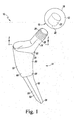
- FIG. 1 shows a femoral orthopaedic implant 10 of a hip prosthesis which includes a head component 12 and an elongated stem component 14 that is configured to be inserted into an intramedullary canal of a patient's surgically-prepared femur (not shown).
- the head component 12 includes a spherical outer surface 16 configured to engage a patient's natural acetabulum (not shown) or a prosthetic acetabular cup implanted into the patient's pelvic bone.
- the head component 12 also includes a distal surface 18 having an opening 20 defined therein, and an inner wall (not shown) extends inwardly from the opening 20 to define an aperture 22 in the head component 12.
- the stem component 14 of the implant 10 includes a core 24 having a neck 26 configured to be coupled to the head component 12.
- the neck 26 includes a plurality of external threads 28 that are configured to engage with a plurality of internal threads (not shown) lining the aperture 22 of the head component 12.
- the neck and the head component may also be configured to be press fit, taper fit, or secured together by other fastening means.
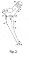
- the core 24 of the stem component 14 also includes a collar 30 and a core body 32 extending distally from the collar 30.
- the neck 26 extends medially and proximally from the collar 30.
- the neck 26, the collar 30, and the core body 32 are formed as a monolithic structure (e.g., a single moulded or cast part).
- the components of the core 24 may also be formed as separate components secured to one another by a mechanical fastener (e.g., screw, bolt, taper fit, etc.), adhesive, or other suitable fastener.
- the stem core 24 is formed from an implant grade metallic material having a high tensile strength and a high elastic modulus (i.e., a high material stiffness).
- the term "high tensile strength” is used to refer to a tensile strength that is greater than 650 MPa.
- the term “high elastic modulus” is used to refer to an elastic modulus or modulus of elasticity that is greater than or equal to 100 GPa.
- the core 24 is formed from cobalt-chromium alloy ("CoCr") having a minimum ultimate tensile strength of 650 MPa and an elastic modulus of approximately 195 GPa.
- the core 24 may be formed any material having a high tensile strength and a high elastic modulus, including, for example, a titanium alloy such as Ti-6Al-4V, which has a minimum ultimate tensile strength of 750 MPa and an elastic modulus of approximately 105 GPa.
- a titanium alloy such as Ti-6Al-4V, which has a minimum ultimate tensile strength of 750 MPa and an elastic modulus of approximately 105 GPa.
- the core 24 of the stem component 14 includes a core body 32, which lies generally in the coronal plane of a patient's body when the implant 10 is secured to the patient's femur. As shown in FIG. 2 , the core body 32 of the core 24 extends from a proximal end 34 attached to the collar 30 to a distal end 36, and the core body 32 has a longitudinal axis 74 that extends through the ends 34, 36.
- the core body 32 includes a medial surface 38 and a lateral surface 40 positioned opposite the medial surface 38.
- the core body 32 has a thickness 42 at the proximal end 34, which is defined between the surfaces 38, 40 of the core body 32.
- the core body 32 has another thickness 44 defined between the surfaces 38, 40 at the distal end 36.
- the thickness 44 is less than the thickness 42, and the core body 32 tapers to decrease in thickness between the proximal end 34 and the distal end 36.
- the thickness 42 is equal to approximately 18 mm, and the thickness 44 is equal to approximately 3.5 mm.
- the thicknesses 42, 44 may be varied depending on the patient's anatomy and the performance requirements of the implant 10.
- the medial surface 38 of the core body 32 is convex.
- the medial surface 38 is defined by a radius 46 (see FIGS. 4 to 7 ) that decreases in magnitude as the medial surface 38 extends from the proximal end 34 of the core body 32 to the distal end 36.
- the lateral surface 40 is also convex in the device shown in the drawings.
- the lateral surface 40 like the medial surface 38, is defined by a radius 48 (see FIGS. 4 to 7 ) that decreases in magnitude as the lateral surface 40 extends from the proximal end 34 of the core body 32 to the distal end 36. While the radii 46, 48 decrease in magnitude, the magnitude of the radius 48 of the lateral surface 40 at each point along the longitudinal axis 74 of the core body 32 is greater than the magnitude of the radius 46 of the medial surface 38.
- the stem component 14 of the implant 10 also includes a shell 50 that is secured to the core 24.
- the shell 50 has a sheath 52 that has a proximal end 54 attached to the collar 30 and a distal end 56 positioned between the collar 30 and the distal end 36 of the core 24.
- the shell 50 also includes a cover layer 58 that extends distally from the sheath 52 to the distal end 36 of the core body 32.
- the sheath 52 and the cover layer 58 are formed as a monolithic structure.
- the components of the shell 50 e.g., sheath 52 and the cover layer 58
- the separate components may be secured to one another by a mechanical fastener (e.g., screw, bolt, taper fit, etc.), adhesive, or other suitable fastener or secured separately to the core 24.
- the shell 50 of the stem component 14 is formed from a metallic foam matrix having a low elastic modulus.
- low elastic modulus is used to refer to an elastic modulus or modulus of elasticity similar to that of a patient's natural femur (i.e., between 10 GPa and 20 GPa).
- the shell 50 is formed from a foam matrix of titanium having an elastic modulus of approximately 10 GPa and an ultimate tensile strength of the foam matrix of titanium is approximately 35 MPa. In that way, the shell 50 has an elastic modulus that is closer to that of a patient's femur.
- the shell 50 may be formed any metallic foam matrix having a low elastic modulus, such as, for example, a CoCr foam matrix having an elastic modulus of approximately 19 GPa, a CoCr alloy foam matrix, a titanium foam alloy matrix, or other foam matrix.
- the core 24 of the stem component 14 in the device shown in the drawings is formed from CoCr having an elastic modulus of approximately 195 GPa while the shell 50 is formed from a foam matrix of titanium having an elastic modulus of approximately 10 GPa.
- the elastic modulus of the shell 50 is therefore approximately 5% of the elastic modulus of the core 24.
- the core may be formed from CoCr having an elastic modulus of approximately 195 GPa and the shell may be formed from a CoCr foam matrix having an elastic modulus of approximately 19 GPa.
- the elastic modulus of the shell is then approximately 10% of the elastic modulus of the core.
- the core may be formed from Ti-6Al-4V having an elastic modulus of approximately 105 GPa and the shell may be formed from a titanium foam matrix having an elastic modulus of approximately 10 GPa.
- the elastic modulus of the shell is then about 10% of the elastic modulus of the core.
- the sheath 52 of the shell 50 has an outer surface 60
- the cover layer 58 has an outer surface 62.
- the outer surfaces 60, 62 define a portion of the external geometry of the implant 10. As such, the outer surfaces 60, 62 engage the portion of the patient's femur defining the intramedullary canal when the implant 10 is inserted into the proximal end of the patient's surgically-prepared femur.
- the outer surface 60 of the sheath 52 is porous to enable bone ingrowth fixation
- the outer surface 62 of the cover layer 58 is non-porous.
- the cover layer 58 may also be porous.
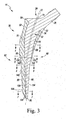
- the core body 32 of the stem core 24 extends through the sheath 52 of the shell 50.
- the core body 32 includes a core segment 64 that is positioned in the sheath 52, and a core segment 66 that is positioned distal of the sheath 52.
- the sheath 52 is attached to and encases a medial surface 68 and a lateral surface 70 of the core segment 64.
- the surfaces 68, 70 form proximal sections of the medial surface 38 and lateral surface 40, respectively, of the core body 32.
- each of the surfaces 68, 70 extends from an outer anterior surface 84 of the core body 32 to an outer posterior surface 86 of the core body 32.
- the core body 32 i.e., the core segments 64, 66
- the shell 50 i.e., the sheath 52 and cover layer 58
- the core body 32 has a longitudinal axis 74 that is defined between the ends 34, 36, and the axis 74 is offset from the axis 72.
- the axis 74 is offset in the medial direction from the axis 72 such that the core body 32 is biassed toward the medial side 80 of the stem component 14 and away from the lateral side 82 of the stem component 14.
- the thickness (referred to herein as the "lateral thickness") of the shell 50 on the lateral side 82 of the stem component 14 is greater than the thickness (referred to herein as the "medial thickness") of the shell 50 on the medial side 80 of the stem component 14.
- the sheath 52 of the foam shell 50 has a proximal end 54 and a distal end 56.
- the ratio of the medial thickness of the shell 50 to the lateral thickness of the shell 50 is between 0.80 and 0.17 at each point along the longitudinal axis 72 between the ends 54, 56 of the sheath 52.
- the medial thickness may be 17% to 80% of the lateral thickness.
- the ratio at each point may be between 0.95 and 0.14.
- the sheath 52 has a lateral thickness 90 and a medial thickness 92 when viewed in a transverse plane extending through the stem component 14 at a point 88 on the axis 72 between the proximal end 54 and the distal end 56 of the sheath 52.
- the lateral thickness 90 of the sheath 52 is defined between a lateral-most point 94 of the lateral surface 70 of the core segment 64 and a lateral-most point 96 of the outer surface 60 of the sheath 52.
- the medial thickness 92 of the sheath 52 is defined between a medial-most point 98 of the medial surface 68 of the core segment 64 and a lateral-most point 100 of the outer surface 60 of the sheath 52.
- Each of the points 94, 96, 98, 100 lies in the coronal plane, as indicated by an imaginary line 102.
- the lateral thickness 90 is greater than the medial thickness 92 at the point 88 on the longitudinal axis 72.
- the thickness 90 of the shell 50 on the lateral side 82 of the stem component 14 is greater than the thickness 92 of the shell 50 on the medial side 80 of the stem component 14.
- the lateral thickness 90 is greater than 5 mm
- the medial thickness 92 is between 2.0 and 4.5 mm.
- the ratio of the medial thickness 92 to the lateral thickness 90 is less than or equal to 0.40 at the point 88.
- the ratio of the medial thickness 92 to the lateral thickness 90 can be about 0.37 at the point 88.
- the thickness of the sheath 52 of the shell 50 on the medial side 80 of the stem component 14 generally decreases from the proximal end 54 and the distal end 56 of the sheath 52.
- the sheath 52 has a lateral thickness 110 and a medial thickness 112 when viewed in a transverse plane extending through the stem component 14 at a point 108 on the longitudinal axis 72 at the distal end 56 of the sheath 52.
- the lateral thickness 110 of the sheath 52 is defined between a lateral-most point 114 of the lateral surface 70 of the core segment 64 and a lateral-most point 116 of the outer surface 60 of the sheath 52.
- the medial thickness 112 of the sheath 52 is defined between a medial-most point 118 of the medial surface 68 of the core segment 64 and a lateral-most point 120 of the outer surface 60 of the sheath 52.
- Each of the points 114, 116, 118, 120 lies in the coronal plane, as indicated by the imaginary line 102.
- the lateral thickness 110 of the sheath 52 is greater than the medial thickness 112 of the sheath 52 at the point 108 on the longitudinal axis 72.
- the lateral thickness 110 is greater than 5 mm.
- the medial thickness 112 at the distal end 56 of the sheath 52 is less than the medial thickness 92 (see FIG. 4 ).
- the medial thickness 92 of sheath 52 in the device shown in the drawings is between 2.0 and 4.5 mm, and the medial thickness 112 of the sheath 52 is between 1.0 and 1.5 mm.
- the ratio of the medial thickness 112 to the lateral thickness 110 is less than or equal to 0.30 at the point 108.
- the ratio of the medial thickness 112 to the lateral thickness 110 may be about 0.17 at the point 108.
- the outer surface 60 of the sheath 52 has a curved or rounded distal surface section 130 at the distal end 56 of the sheath 52.
- the distal surface section 130 has an edge 132 that extends around the core body 32 of the stem core 24 and the cover layer 58 of the shell 50.
- the core body 32 also includes a core segment 66 that is positioned distal of the end 56 of the sheath 52. The core segment 66 extends from the edge 132 of the sheath 52 to the distal end 36 of the core body 32.
- the core segment 66 has a medial surface 134 that forms a distal section of the medial surface 38 of the core body 32.
- the core segment 66 also has a lateral surface 136 that forms a distal section of the lateral surface 40 of the core body 32.
- the medial surface 134 and the lateral surface 136 extend from the outer anterior surface 84 of the core body 32 to the outer posterior surface 86 of the core body 32.
- the cover layer 58 of the shell 50 is attached to only the lateral surface 136 of the core segment 66.
- the medial surface 134 of the core segment 66 forms a portion of the external geometry of the implant 10 such that the medial surface 134 may engage the patient's bone when the implant 10 is inserted into the intramedullary canal.
- the cover layer 58 has a body 140 that extends from a proximal end 142 attached to the sheath 52.
- the cover layer body 140 extends to a distal end 144 connected to a tip 128 of the cover layer 58.
- the tip 128 extends to the distal end of the stem component 14.
- the tip 128 is shaped to provide relief during insertion of the stem component 14 into the proximal end of the patient's femur.
- the tip 128 may be omitted and the body 140 of the cover layer 58 may extend to the distal end of the stem component 14.
- the stem component 14 has a medial-lateral thickness that is the sum of the thickness of the cover layer body 140 and the thickness of the lower core segment 66.
- the ratio of the thickness of the cover layer body 140 to the thickness of the segment 66 is between 0.80 and 0.57 at each point along the longitudinal axis 72 between the ends 142, 144 of the cover layer body 140.
- the cover layer body thickness may be 57% to 80% of the thickness of the core segment 66.
- the ratio at each point may be between 0.96 and 0.46.
- the tip 128 of the cover layer 58 is tapered such that the thickness of the cover layer 58 decreases from the distal end 144 of the cover layer body 140 to the distal end of the stem component 14.
- the cover layer 58 makes up a significant percentage of the overall thickness of stem component 14.
- the ratio of the thickness of the cover layer body 140 to the overall thickness of the stem component 14 is between 0.45 and 0.36 at each point between the ends 142, 144 of the cover layer body 140.
- the cover layer body 140 may be 36% to 45% of the overall thickness of the stem component 14 between the ends 142, 144.
- the ratio of the thickness of the cover layer body 140 to the overall thickness may be between 0.54 and 0.29.
- the thickness of the cover layer body 140 decreases along the longitudinal axis 72 between the ends 142, 144.
- the cover layer body 140 has a lateral thickness 150 when viewed in a transverse plane that extends through the stem component 14 between the ends 142, 144 at the point 138 on the axis 72.
- the lateral thickness 150 of the cover layer body 140 is defined between a lateral-most point 152 of the lateral surface 136 of the core segment 66 and a lateral-most point 154 of the outer surface 62 of the cover layer 58.
- the lateral thickness 150 is greater than 4.5 mm.
- the core segment 66 at the point 138 has a thickness 146 defined between the lateral-most point 152 of the core segment 66 and a medial-most point 148 of the core segment 66.
- the thickness 146 in the device shown in the drawings is greater than 7.0 mm.
- the ratio of the lateral thickness 150 to the core thickness 146 at the point 138 is between 0.65 and 0.57. Optionally, the ratio may be about 0.59 at the point 138.
- the ratio of the lateral thickness 150 to the overall thickness of the stem component 14 may be between 0.39 and 0.29.
- the ratio of the lateral thickness 150 to the overall thickness may be about 0.37 at the point 138.
- the cover layer body 140 has a lateral thickness 158 when viewed in a transverse plane extending through the stem component 14 at a point 164 on the axis 72 at the distal end 144 of the cover layer 58.
- the lateral thickness 158 of the body 140 is defined between a lateral-most point 160 of the lateral surface 136 of the core segment 66 and a lateral-most point 162 of the outer surface 62 of the cover layer 58.
- the lateral thickness 158 of the body 140 is between 3 mm and 4 mm. In other words, the lateral thickness 158 of the cover layer body 140 at the distal end 144 of the cover layer 58 is less than the lateral thickness 150 of the body 140 between the ends 142, 144.
- the core segment 66 at the point 164 has a thickness 166 defined between the lateral-most point 160 of the core segment 66 and a medial-most point 168 of the core segment 66.
- the thickness 166 in the device shown in the drawings is greater than 3.5 mm.
- the ratio of the lateral thickness 158 to the core thickness 166 at the point 164 is between 0.85 and 0.57. Optionally, the ratio is about 0.80 at the point 164 along the longitudinal axis 72.
- the ratio of the lateral thickness 158 to the overall thickness of the stem component 14 is between 0.40 and 0.29.
- the ratio of the lateral thickness 158 to the overall thickness is about 0.45 at the point 164.
- the foam shell 50 comprises a significant portion of the stem component 14, as indicated by the ratio between the cross-sectional area of the foam shell 50 (identified as ⁇ in FIGS. 4 to 7 ) to the total cross-sectional area of the stem component 14 (designated ⁇ in FIGS. 4 to 7 ).
- the total cross-sectional area of the stem component comprises the cross-sectional area of the foam shell 50 and the cross-sectional area of the core body 32.
- the ratio of the cross-sectional area of the foam shell 50 designated ⁇ in FIGS. 4 to 7
- the cross-sectional area of the stem component 14 designated ⁇ in FIGS.
- the foam shell 50 may form 37% to 55% of the cross-sectional area of the stem component 14 at each of those points.
- the ratio at each point may be between 0.70 and 0.30.
- a table 170 shows values for the cross-sectional area ⁇ of the foam shell 50, the cross-sectional area ⁇ of the core body 32, and the cross-sectional area ⁇ of the stem component 14 at each of the points 88, 108, 138, 164 along the axis 72.
- the total cross-sectional area ⁇ of the stem component 14 is equal to the sum of the cross-sectional area ⁇ of the foam shell 50 and the cross-sectional area ⁇ of the core body 32 at each point along the axis 72 above the tip 128 of the foam shell 50.
- the ratio of cross-sectional area ⁇ to the cross-sectional area ⁇ ranges from 0.46 to 0.54.
- the ratio of cross-sectional area ⁇ to the cross-sectional area ⁇ is between 0.55 and 0.47.
- the ratio of cross-sectional area ⁇ to the cross-sectional area ⁇ between the ends 54, 56 of the sheath 52 may be between 0.70 and 0.38.
- the ratio of cross-sectional area ⁇ to the cross-sectional area ⁇ is between 0.47 and 0.37.
- the ratio of cross-sectional area ⁇ to the cross-sectional area ⁇ between the ends 142, 144 of the cover layer body 140 may be between 0.56 and 0.30.
- the implant 10 is inserted into a proximal end of a patient's surgically-prepared femur.
- the elongated stem component 14 is received in the intramedullary canal and the sheath 52 and the cover layer 58 of the shell 50 engage the portion of the patient's femur surrounding the canal.
- the core 24 is sized and shaped to meet the minimum strength requirements of the implant 10, while the shell 50 is configured to possess the external geometry necessary to fit into the intramedullary canal.
- the combination of the high tensile strength/high elastic modulus core 24 with the low modulus shell 50 results in a reduced stiffness for the implant 10 such that stress shielding of the patient's bone is reduced.
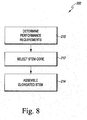
- FIG. 8 shows steps in a method 200 of manufacturing the elongated stem component 14 of the implant 10, in which the performance requirements of the stem component 14 are determined and the stem core 24 of the stem component 14 is procured. The stem core 24 and the shell 50 may then be assembled to form the stem component 14.
- the performance requirements of the stem component 14 are determined.
- the performance requirements for the stem component 14 may vary between different patients such that a customized stem component 14 may be required.
- the performance requirements include the external geometry and the minimum endurance and performance requirements, such as, for example, the minimum tensile strength and the minimum stiffness of the stem component 14.
- the core 24 of the stem component 14 is selected in block 212.
- the core 24 may be a generic core that may be used with multiple implant sizes.
- the core 24 may be a customized, patient-specific component designed to satisfy the performance requirements of a particular patient. Whether the core 24 is generic or custom, the selected core 24 of the component 14 is sized and shaped to provide the minimum strength of the implant 10.
- the minimum strength of the core 24 is determined in accordance with International Organization for Standardization Standard No. 7206-4:2010 "Implants for Surgery-Partial and Total Hip Joint Prostheses -- Part 4: Determination of Endurance Properties and Performance of Stemmed Femoral Components" and Standard No. 7206-6:1992 "Implants for Surgery -- Partial and Total Hip Joint Prostheses -- Part 6: Determination of Endurance Properties of Head and Neck Region of Stemmed Femoral Components".
- the stem component 14 is assembled.
- a metallic foam matrix which will form the shell 50 of the stem component 14, is procured.
- the metallic foam matrix may be compressed around the core 24 such that the core 24 is received in a channel within the foam matrix.
- the foam matrix may then be machined to the required external geometry of the shell 50.
- the metallic foam matrix may be compressed separately into the shape of shell 50.
- a channel sized to receive the core 24 may be machined in the shell 50 before the shell 50 is assembled with the core 24.
- a sintering operation may be used to secure the shell 50 to the core 24. It should also be appreciated that the shell 50 and the core 24 may be secured by a brazing operation, a press-fit, or other securing means.
Landscapes
- Health & Medical Sciences (AREA)
- Orthopedic Medicine & Surgery (AREA)
- Cardiology (AREA)
- Oral & Maxillofacial Surgery (AREA)
- Transplantation (AREA)
- Engineering & Computer Science (AREA)
- Biomedical Technology (AREA)
- Heart & Thoracic Surgery (AREA)
- Vascular Medicine (AREA)
- Life Sciences & Earth Sciences (AREA)
- Animal Behavior & Ethology (AREA)
- General Health & Medical Sciences (AREA)
- Public Health (AREA)
- Veterinary Medicine (AREA)
- Prostheses (AREA)
Abstract
Description
- The invention relates to orthopaedic prostheses, including prostheses which can be used in hip replacement surgery.
- Joint arthroplasty is a well-known surgical procedure by which a diseased and/or damaged natural joint is replaced by a prosthetic joint. The prosthetic joint may include a prosthesis that is implanted into one or more of the patient's bones. Many hip prostheses include a femoral prosthesis that is implanted into a patient's femur. A femoral prosthesis typically includes an elongated stem component that is received in the medullary canal of the patient's femur and a spherically-shaped head component that bears against the patient's acetabulum or a prosthetic replacement acetabular cup.
- Many femoral prostheses are formed from metallic materials or a combination of metallic and polymeric materials. According to Wolff's law, a patient's bone tissue will remodel in proportion to the stress applied it. Because elongated stem components formed from metal typically have an elastic modulus greater than the elastic modulus of the patient's bone, metallic stem components may shield the patient's bone from stress such that the proximal femoral bone does not remodel to an effective degree, possibly resulting in a loss of support for the implant and/or implant failures.
- The invention provides an orthopaedic prosthesis which includes a metallic foam shell including a sheath, and a metallic core including a neck positioned proximal of the sheath a first core segment positioned in the sheath, and a second core segment positioned distal of the sheath. The neck of the metallic core is configured to receive a femoral head component. The metallic foam shell further includes a cover layer extending distally from the sheath that engages only a lateral surface of the second core segment. When the orthopaedic prosthesis is viewed in a transverse plane extending through the cover layer of the metallic foam shell, the cover layer defines a first cross-sectional area, the cover layer and the second core segment define a second cross-sectional area, and a ratio of the first cross-sectional area to the second cross-sectional area is greater than 0.30.
- Optionally, the ratio of the first cross-sectional area to the second cross-sectional area may be between 0.35 and 0.47. Optionally, the ratio of the first cross-sectional area to the second cross-sectional area may be less than 0.56.
- Optionally, when the orthopaedic prosthesis is viewed in a second transverse plane extending through the sheath of the metallic foam shell, the sheath may define a third cross-sectional area, the sheath and the first core segment may define a fourth cross-sectional area, and a ratio of the third cross-sectional area to the fourth cross-sectional area may be greater than 0.38. Optionally, the ratio of the third cross-sectional area to the fourth cross-sectional area may be between 0.46 and 0.54.
- Optionally, the ratio of the third cross-sectional area to the fourth cross-sectional area may be less than 0.70. Optionally, the ratio of the third cross-sectional area to the fourth cross-sectional area may be greater than the ratio of the first cross-sectional area to the second cross-sectional area.
- Optionally, the cover layer of the metallic foam shell may extend distally from a proximal end attached to the sheath, and the transverse plane extends through the proximal end of the cover layer. When the orthopaedic prosthesis is viewed in the transverse plane, the cover layer has a first thickness, the second core segment has a second thickness, and a ratio of the first thickness to the second thickness may be greater than 0.46.
- Optionally, the first thickness may be greater than 3 mm. When the orthopaedic prosthesis is viewed in the transverse plane, a medial surface of the first core segment may be convex and a lateral surface of the first core segment may be convex.
- Optionally, when the orthopaedic prosthesis is viewed in the transverse plane, the medial surface of the first core segment may be defined by a first radius, and the lateral surface of the first core segment may be defined by a second radius that is greater than the first radius.
- Optionally, the first core segment of the metallic core may have a medial surface and a lateral surface positioned opposite the medial surface of the first core segment, and the sheath may have a medial surface and a lateral surface positioned opposite the medial surface of the sheath. When the orthopaedic prosthesis is viewed in the transverse plane, a first thickness may be defined between a lateral-most point of the lateral surface of the sheath and a lateral-most point of the lateral surface of the first core segment, a second thickness may be defined between a medial-most point of the medial surface of the sheath and a medial-most point of the medial surface of the first core segment, and a ratio of the second thickness to the first thickness may be greater than 0.14.
- The invention also provides an orthopaedic prosthesis for a patient which includes an elongate femoral stem component having a longitudinal axis. The stem component includes a metallic foam shell having a first elastic modulus, and a metallic core including a neck positioned proximal of the shell and a body that extends through the shell. The core has a second elastic modulus which is greater than the first elastic modulus. The metallic foam shell defines a first cross-sectional area at a first point on the longitudinal axis, the stem component defines a second cross-sectional area at the first point, and the ratio of the first cross-sectional area to the second cross-sectional area is greater than 0.38. The metallic foam shell defines a third cross-sectional area at a second point on the longitudinal axis that is distal of the first point, the stem component defines a fourth cross-sectional area at the second point, and the ratio of the third cross-sectional area to the fourth cross-sectional area is greater than the ratio of the first cross-sectional area to the second cross-sectional area.
- Optionally, the metallic foam shell may define a fifth cross-sectional area at a third point on the longitudinal axis. The third point may be distal of the second point. The stem component may define a sixth cross-sectional area at the third point, and a ratio of the fifth cross-sectional area to the sixth cross-sectional area may be less than the ratio of the third cross-sectional area to the fourth cross-sectional area.
- Optionally, the ratio of the fifth cross-sectional area to the sixth cross-sectional area may be between 0.30 and 0.56.
- Optionally, the metallic foam shell may include a cover layer attached to only a lateral surface of the metallic core at the third point on the longitudinal axis.
- Optionally, the ratio of the third cross-sectional area to the fourth cross-sectional area may be less than 0.70.
- The invention also provides an orthopaedic prosthesis which includes an elongated femoral stem component having a longitudinal axis. The stem component includes a metallic foam shell including a sheath, and a metallic core including a neck positioned proximal of the sheath that is configured to receive a femoral head component, a first core segment positioned in the sheath, and a second core segment positioned distal of the sheath. The metallic foam shell further includes a cover layer extending distally from the sheath and engaging only a lateral surface of the second core segment. The cover layer defines a first cross-sectional area at a first point on the longitudinal axis. The cover layer and the second core segment define a second cross-sectional area at the first point, and a ratio of the first cross-sectional area to the second cross-sectional area is greater than 0.30.
- Optionally, the sheath may define a third cross-sectional area at a second point on the longitudinal axis, the sheath and the first core segment may define a fourth cross-sectional area at the second point, and a ratio of the third cross-sectional area to the fourth cross-sectional area may be greater than 0.38.
- The invention also provides an orthopaedic prosthesis which includes a metallic foam shell and a metallic core. The foam shell includes a sheath and a cover layer. The metallic core includes a neck positioned proximal of the sheath, the neck being configured to receive a femoral head component, a first core segment positioned in the sheath, and a second core segment positioned distal of the sheath. The cover layer of the foam shell extends distally from the sheath, and the cover layer engages only a lateral surface of the second core segment.
- Optionally, the first core segment of the metallic core may have a medial surface and a lateral surface positioned opposite the medial surface. Optionally, the sheath may have a medial surface and a lateral surface positioned opposite the medial surface. Optionally, when the orthopaedic prosthesis is viewed in a transverse plane, a first thickness may be defined between a medial-most point of the medial surface of the sheath and a medial-most point of the medial surface of the first core segment and a second thickness may be defined between a lateral-most point of the lateral surface of the sheath and a lateral-most point of the lateral surface of the first core segment. The first thickness may be less than the second thickness.
- Optionally, the transverse plane may be a first transverse plane extending through the orthopaedic prosthesis between a proximal end of the sheath and a distal end of the sheath. When the orthopaedic prosthesis is viewed in a second transverse plane extending through the orthopaedic prosthesis at the distal end of the sheath, a third thickness may be defined between a medial-most point of the medial surface of the sheath and a medial-most point of the medial surface of the first core segment. The third thickness may be less than the first thickness.
- Optionally, the third thickness may be less than 1.5 mm. Optionally, when the orthopaedic prosthesis is viewed in the second transverse plane, a fourth thickness may be defined between a lateral-most point of the lateral surface of the sheath and a lateral-most point of the lateral surface of the first core segment. The fourth thickness may be greater than 5 mm.
- Optionally, when the orthopaedic prosthesis is viewed in the second transverse plane, the medial surface of the first core segment may be convex, and the lateral surface of the first core segment may be convex. Optionally, when the orthopaedic prosthesis is viewed in the second transverse plane, the medial surface of the first core segment may be defined by a first radius, and the lateral surface of the first core segment may be defined by a second radius that is greater than the first radius.
- Optionally, the cover layer of the metallic foam shell may have a body that extends from a proximal end attached to the sheath to a distal end. The body may have a first thickness at the proximal end and a second thickness at the distal end. The second thickness may be less than the first thickness. Optionally, the first thickness of the body may be greater than 3 mm.
- Optionally, the sheath of the metallic foam shell may have a porous outer surface. Optionally, the cover layer of the metallic foam shell may have a non-porous outer surface.
- Optionally, the metallic foam shell may have a first elastic modulus, and the metallic core may have a second elastic modulus. The first elastic modulus may be approximately 5% of the second elastic modulus. Optionally, the metallic foam shell may be shaped to engage a surgically-prepared proximal end of a patient's femur. Optionally, the first elastic modulus may be approximately 10% of the second elastic modulus. Optionally, the metallic foam shell may be shaped to engage a surgically-prepared proximal end of a patient's femur.
- The invention also provides an orthopaedic prosthesis which includes a metallic foam shell having a first elastic modulus. The shell has an outer surface that engages a patient's bony anatomy. The orthopaedic prosthesis includes a metallic core having a neck positioned proximal of the shell and a body that extends through the shell. The core has a second elastic modulus greater than the first elastic modulus of the shell. When the orthopaedic prosthesis is viewed in a transverse plane extending through the shell and the core, a first thickness is defined between a medial-most point of the outer surface of the shell and a medial-most point of a medial surface of the core, and a second thickness is defined between a lateral-most point of the outer surface of the shell and a lateral-most point of a lateral surface of the core. The first thickness is less than the second thickness.
- Optionally, the metallic core may be formed from a cobalt-chromium alloy. Optionally, the metallic foam shell may be formed from titanium. Optionally, the metallic foam shell may be formed from a cobalt-chromium alloy. Optionally, the metallic foam shell may be formed from titanium alloy.
- Optionally, the body of the metallic core may include a first core segment coupled to the neck and positioned in the metallic foam shell and a second core segment positioned distal of the metallic foam shell. Optionally, the metallic foam shell may include a cover layer attached to only a lateral surface of the second core segment.
- The invention also provides a method of manufacturing an orthopaedic prosthesis, which includes producing a shell from a metallic foam material having a first elastic modulus, producing a stem core from a metallic material having a second elastic modulus greater than the first elastic modulus. The stem core includes a neck configured to receive a femoral head component. The method also includes securing the shell to the stem core such that the shell is positioned over a proximal segment of the stem core, and a cover layer of the shell extends along a lateral surface of a distal segment of the stem core.
- Optionally, the step of producing the shell may include forming a sheath over the proximal segment of the stem core such that the proximal segment of the stem core is encased therein. Optionally, the step of forming the sheath may include setting a medial thickness of the shell to between 1 mm and 1.5 mm at a distal end of the sheath.
- Optionally, the step of securing the shell to the core may include sintering the shell to the core. Optionally, the step of producing the shell from the metallic foam material may include compressing the metallic foam material around the stem core, and machining the metallic foam material to form the shell. Optionally, the step of producing the shell from the metallic foam material may include compressing the metallic foam material to form an outer geometry of the shell, and machining a channel in the metallic foam material sized to receive the stem core.
- The invention is described below by way of example with reference to the accompanying drawings, in which:
-
FIG. 1 is a perspective view of an orthopaedic implant. -
FIG. 2 is a perspective view of a core of the orthopaedic implant ofFIG. 1 . -
FIG. 3 is a cross-sectional view of the orthopaedic implant taken along the line 3-3 inFIG. 1 . -
FIG. 4 is a cross-sectional view of the orthopaedic implant taken along the line 4-4 inFIG. 3 . -
FIG. 5 is a cross-sectional view of the orthopaedic implant taken along the line 5-5 inFIG. 3 . -
FIG. 6 is a cross-sectional view of the orthopaedic implant taken along the line 6-6 inFIG. 3 . -
FIG. 7 is a cross-sectional view of the orthopaedic implant taken along the line 7-7 inFIG. 3 . -
FIG. 8 is a simplified block diagram of a process for manufacturing the orthopaedic implant ofFIGS. 1 to 7 . -
FIG. 9 is a table showing cross-sectional areas of various components of the orthopaedic implant ofFIG. 1 at various points along the length of the implant. - Terms representing anatomical references, such as anterior, posterior, medial, lateral, superior, inferior, transverse, and coronal, may be used throughout this document to refer to the orthopaedic implants or prostheses and surgical instruments described herein as well as to refer to the patient's natural anatomy. Such terms have well-understood meanings in both the study of anatomy and the field of orthopaedics. Use of such anatomical reference terms in this document is intended to be consistent with their well-understood meanings unless noted otherwise.
- Referring to the drawings,
FIG. 1 shows a femoralorthopaedic implant 10 of a hip prosthesis which includes ahead component 12 and anelongated stem component 14 that is configured to be inserted into an intramedullary canal of a patient's surgically-prepared femur (not shown). Thehead component 12 includes a sphericalouter surface 16 configured to engage a patient's natural acetabulum (not shown) or a prosthetic acetabular cup implanted into the patient's pelvic bone. Thehead component 12 also includes adistal surface 18 having anopening 20 defined therein, and an inner wall (not shown) extends inwardly from theopening 20 to define anaperture 22 in thehead component 12. - The
stem component 14 of theimplant 10 includes a core 24 having aneck 26 configured to be coupled to thehead component 12. In the device shown in the drawings, theneck 26 includes a plurality ofexternal threads 28 that are configured to engage with a plurality of internal threads (not shown) lining theaperture 22 of thehead component 12. The neck and the head component may also be configured to be press fit, taper fit, or secured together by other fastening means. - As shown in
FIG. 2 , thecore 24 of thestem component 14 also includes acollar 30 and acore body 32 extending distally from thecollar 30. As shown inFIG. 1 , theneck 26 extends medially and proximally from thecollar 30. In the device shown in the drawings, theneck 26, thecollar 30, and thecore body 32 are formed as a monolithic structure (e.g., a single moulded or cast part). The components of the core 24 (e.g., theneck 26, thecollar 30, and the core body 32) may also be formed as separate components secured to one another by a mechanical fastener (e.g., screw, bolt, taper fit, etc.), adhesive, or other suitable fastener. - The
stem core 24 is formed from an implant grade metallic material having a high tensile strength and a high elastic modulus (i.e., a high material stiffness). The term "high tensile strength" is used to refer to a tensile strength that is greater than 650 MPa. The term "high elastic modulus" is used to refer to an elastic modulus or modulus of elasticity that is greater than or equal to 100 GPa. In the device shown in the drawings, thecore 24 is formed from cobalt-chromium alloy ("CoCr") having a minimum ultimate tensile strength of 650 MPa and an elastic modulus of approximately 195 GPa. The core 24 may be formed any material having a high tensile strength and a high elastic modulus, including, for example, a titanium alloy such as Ti-6Al-4V, which has a minimum ultimate tensile strength of 750 MPa and an elastic modulus of approximately 105 GPa. - As described above, the
core 24 of thestem component 14 includes acore body 32, which lies generally in the coronal plane of a patient's body when theimplant 10 is secured to the patient's femur. As shown inFIG. 2 , thecore body 32 of thecore 24 extends from aproximal end 34 attached to thecollar 30 to adistal end 36, and thecore body 32 has alongitudinal axis 74 that extends through theends core body 32 includes amedial surface 38 and alateral surface 40 positioned opposite themedial surface 38. When thecore 24 of thestem component 14 is viewed in the coronal plane, thecore body 32 has athickness 42 at theproximal end 34, which is defined between thesurfaces core body 32. Thecore body 32 has anotherthickness 44 defined between thesurfaces distal end 36. In the device shown in the drawings, thethickness 44 is less than thethickness 42, and thecore body 32 tapers to decrease in thickness between theproximal end 34 and thedistal end 36. In the device shown in the drawings, thethickness 42 is equal to approximately 18 mm, and thethickness 44 is equal to approximately 3.5 mm. Thethicknesses implant 10. - In the device shown in the drawings, the
medial surface 38 of thecore body 32 is convex. As described below, themedial surface 38 is defined by a radius 46 (seeFIGS. 4 to 7 ) that decreases in magnitude as themedial surface 38 extends from theproximal end 34 of thecore body 32 to thedistal end 36. Thelateral surface 40 is also convex in the device shown in the drawings. Thelateral surface 40, like themedial surface 38, is defined by a radius 48 (seeFIGS. 4 to 7 ) that decreases in magnitude as thelateral surface 40 extends from theproximal end 34 of thecore body 32 to thedistal end 36. While theradii radius 48 of thelateral surface 40 at each point along thelongitudinal axis 74 of thecore body 32 is greater than the magnitude of theradius 46 of themedial surface 38. - Returning to
FIG. 1 , thestem component 14 of theimplant 10 also includes ashell 50 that is secured to thecore 24. Theshell 50 has asheath 52 that has aproximal end 54 attached to thecollar 30 and adistal end 56 positioned between thecollar 30 and thedistal end 36 of thecore 24. Theshell 50 also includes acover layer 58 that extends distally from thesheath 52 to thedistal end 36 of thecore body 32. In the device shown in the drawings, thesheath 52 and thecover layer 58 are formed as a monolithic structure. The components of the shell 50 (e.g.,sheath 52 and the cover layer 58) may instead be formed as separate components. The separate components may be secured to one another by a mechanical fastener (e.g., screw, bolt, taper fit, etc.), adhesive, or other suitable fastener or secured separately to thecore 24. - The
shell 50 of thestem component 14 is formed from a metallic foam matrix having a low elastic modulus. The term "low elastic modulus" is used to refer to an elastic modulus or modulus of elasticity similar to that of a patient's natural femur (i.e., between 10 GPa and 20 GPa). In the device shown in the drawings, theshell 50 is formed from a foam matrix of titanium having an elastic modulus of approximately 10 GPa and an ultimate tensile strength of the foam matrix of titanium is approximately 35 MPa. In that way, theshell 50 has an elastic modulus that is closer to that of a patient's femur. Theshell 50 may be formed any metallic foam matrix having a low elastic modulus, such as, for example, a CoCr foam matrix having an elastic modulus of approximately 19 GPa, a CoCr alloy foam matrix, a titanium foam alloy matrix, or other foam matrix. - As described above, the
core 24 of thestem component 14 in the device shown in the drawings is formed from CoCr having an elastic modulus of approximately 195 GPa while theshell 50 is formed from a foam matrix of titanium having an elastic modulus of approximately 10 GPa. The elastic modulus of theshell 50 is therefore approximately 5% of the elastic modulus of thecore 24. The core may be formed from CoCr having an elastic modulus of approximately 195 GPa and the shell may be formed from a CoCr foam matrix having an elastic modulus of approximately 19 GPa. The elastic modulus of the shell is then approximately 10% of the elastic modulus of the core. The core may be formed from Ti-6Al-4V having an elastic modulus of approximately 105 GPa and the shell may be formed from a titanium foam matrix having an elastic modulus of approximately 10 GPa. The elastic modulus of the shell is then about 10% of the elastic modulus of the core. - As shown in
FIG. 1 , thesheath 52 of theshell 50 has anouter surface 60, and thecover layer 58 has anouter surface 62. Theouter surfaces implant 10. As such, theouter surfaces implant 10 is inserted into the proximal end of the patient's surgically-prepared femur. In the device shown in the drawings, theouter surface 60 of thesheath 52 is porous to enable bone ingrowth fixation, and theouter surface 62 of thecover layer 58 is non-porous. Thecover layer 58 may also be porous. - As shown in
FIG. 3 , thecore body 32 of thestem core 24 extends through thesheath 52 of theshell 50. Thecore body 32 includes acore segment 64 that is positioned in thesheath 52, and acore segment 66 that is positioned distal of thesheath 52. Thesheath 52 is attached to and encases amedial surface 68 and alateral surface 70 of thecore segment 64. Thesurfaces medial surface 38 andlateral surface 40, respectively, of thecore body 32. In the device shown in the drawings, each of thesurfaces anterior surface 84 of thecore body 32 to anouter posterior surface 86 of thecore body 32. - The core body 32 (i.e., the
core segments 64, 66) and the shell 50 (i.e., thesheath 52 and cover layer 58) cooperate to define alongitudinal axis 72 of thestem component 14, which extends between theproximal end 34 and thedistal end 36. As described above, thecore body 32 has alongitudinal axis 74 that is defined between theends axis 74 is offset from theaxis 72. In the device shown in the drawings, theaxis 74 is offset in the medial direction from theaxis 72 such that thecore body 32 is biassed toward themedial side 80 of thestem component 14 and away from thelateral side 82 of thestem component 14. Additionally, the thickness (referred to herein as the "lateral thickness") of theshell 50 on thelateral side 82 of thestem component 14 is greater than the thickness (referred to herein as the "medial thickness") of theshell 50 on themedial side 80 of thestem component 14. - As described above, the
sheath 52 of thefoam shell 50 has aproximal end 54 and adistal end 56. In the device shown in the drawings, the ratio of the medial thickness of theshell 50 to the lateral thickness of theshell 50 is between 0.80 and 0.17 at each point along thelongitudinal axis 72 between theends sheath 52. In other words, at any point between theends sheath 52, the medial thickness may be 17% to 80% of the lateral thickness. Optionally, the ratio at each point may be between 0.95 and 0.14. - For example, as shown in
FIG. 4 , thesheath 52 has alateral thickness 90 and amedial thickness 92 when viewed in a transverse plane extending through thestem component 14 at apoint 88 on theaxis 72 between theproximal end 54 and thedistal end 56 of thesheath 52. Thelateral thickness 90 of thesheath 52 is defined between alateral-most point 94 of thelateral surface 70 of thecore segment 64 and alateral-most point 96 of theouter surface 60 of thesheath 52. Themedial thickness 92 of thesheath 52 is defined between amedial-most point 98 of themedial surface 68 of thecore segment 64 and alateral-most point 100 of theouter surface 60 of thesheath 52. Each of thepoints imaginary line 102. - As shown in
FIG. 4 , thelateral thickness 90 is greater than themedial thickness 92 at thepoint 88 on thelongitudinal axis 72. In other words, thethickness 90 of theshell 50 on thelateral side 82 of thestem component 14 is greater than thethickness 92 of theshell 50 on themedial side 80 of thestem component 14. In the device shown in the drawings, thelateral thickness 90 is greater than 5 mm, and themedial thickness 92 is between 2.0 and 4.5 mm. The ratio of themedial thickness 92 to thelateral thickness 90 is less than or equal to 0.40 at thepoint 88. Optionally, the ratio of themedial thickness 92 to thelateral thickness 90 can be about 0.37 at thepoint 88. - As shown in
FIGS. 3 to 5 , the thickness of thesheath 52 of theshell 50 on themedial side 80 of thestem component 14 generally decreases from theproximal end 54 and thedistal end 56 of thesheath 52. As shown inFIG. 5 , thesheath 52 has alateral thickness 110 and amedial thickness 112 when viewed in a transverse plane extending through thestem component 14 at apoint 108 on thelongitudinal axis 72 at thedistal end 56 of thesheath 52. Thelateral thickness 110 of thesheath 52 is defined between alateral-most point 114 of thelateral surface 70 of thecore segment 64 and alateral-most point 116 of theouter surface 60 of thesheath 52. Themedial thickness 112 of thesheath 52 is defined between a medial-most point 118 of themedial surface 68 of thecore segment 64 and alateral-most point 120 of theouter surface 60 of thesheath 52. Each of thepoints imaginary line 102. - As shown in
FIG. 5 , thelateral thickness 110 of thesheath 52 is greater than themedial thickness 112 of thesheath 52 at thepoint 108 on thelongitudinal axis 72. In the device shown in the drawings, thelateral thickness 110 is greater than 5 mm. Additionally, themedial thickness 112 at thedistal end 56 of thesheath 52 is less than the medial thickness 92 (seeFIG. 4 ). As described above, themedial thickness 92 ofsheath 52 in the device shown in the drawings is between 2.0 and 4.5 mm, and themedial thickness 112 of thesheath 52 is between 1.0 and 1.5 mm. The ratio of themedial thickness 112 to thelateral thickness 110 is less than or equal to 0.30 at thepoint 108. Optionally, the ratio of themedial thickness 112 to thelateral thickness 110 may be about 0.17 at thepoint 108. - Returning to
FIG. 3 , theouter surface 60 of thesheath 52 has a curved or roundeddistal surface section 130 at thedistal end 56 of thesheath 52. Thedistal surface section 130 has anedge 132 that extends around thecore body 32 of thestem core 24 and thecover layer 58 of theshell 50. As described above, thecore body 32 also includes acore segment 66 that is positioned distal of theend 56 of thesheath 52. Thecore segment 66 extends from theedge 132 of thesheath 52 to thedistal end 36 of thecore body 32. - The
core segment 66 has amedial surface 134 that forms a distal section of themedial surface 38 of thecore body 32. Thecore segment 66 also has alateral surface 136 that forms a distal section of thelateral surface 40 of thecore body 32. Themedial surface 134 and thelateral surface 136 extend from the outeranterior surface 84 of thecore body 32 to theouter posterior surface 86 of thecore body 32. As shown inFIG. 3 , thecover layer 58 of theshell 50 is attached to only thelateral surface 136 of thecore segment 66. Themedial surface 134 of thecore segment 66 forms a portion of the external geometry of theimplant 10 such that themedial surface 134 may engage the patient's bone when theimplant 10 is inserted into the intramedullary canal. - As shown in
FIG. 3 , thecover layer 58 has abody 140 that extends from aproximal end 142 attached to thesheath 52. Thecover layer body 140 extends to adistal end 144 connected to atip 128 of thecover layer 58. Thetip 128 extends to the distal end of thestem component 14. In the device shown in the drawings, thetip 128 is shaped to provide relief during insertion of thestem component 14 into the proximal end of the patient's femur. Thetip 128 may be omitted and thebody 140 of thecover layer 58 may extend to the distal end of thestem component 14. - The
stem component 14 has a medial-lateral thickness that is the sum of the thickness of thecover layer body 140 and the thickness of thelower core segment 66. In the device shown in the drawings, the ratio of the thickness of thecover layer body 140 to the thickness of thesegment 66 is between 0.80 and 0.57 at each point along thelongitudinal axis 72 between theends cover layer body 140. In other words, at any point between theends body 140, the cover layer body thickness may be 57% to 80% of the thickness of thecore segment 66. Optionally, the ratio at each point may be between 0.96 and 0.46. As shown inFIG. 3 , thetip 128 of thecover layer 58 is tapered such that the thickness of thecover layer 58 decreases from thedistal end 144 of thecover layer body 140 to the distal end of thestem component 14. - As shown in
FIGS. 3 ,6 and 7 , thecover layer 58 makes up a significant percentage of the overall thickness ofstem component 14. The ratio of the thickness of thecover layer body 140 to the overall thickness of thestem component 14 is between 0.45 and 0.36 at each point between theends cover layer body 140. In other words, thecover layer body 140 may be 36% to 45% of the overall thickness of thestem component 14 between theends cover layer body 140 to the overall thickness may be between 0.54 and 0.29. - In the device shown in the drawings, the thickness of the
cover layer body 140 decreases along thelongitudinal axis 72 between theends FIG. 6 , thecover layer body 140 has alateral thickness 150 when viewed in a transverse plane that extends through thestem component 14 between theends point 138 on theaxis 72. Thelateral thickness 150 of thecover layer body 140 is defined between a lateral-most point 152 of thelateral surface 136 of thecore segment 66 and alateral-most point 154 of theouter surface 62 of thecover layer 58. As shown inFIG. 6 , thelateral thickness 150 is greater than 4.5 mm. - As shown in
FIG. 6 , thecore segment 66 at thepoint 138 has athickness 146 defined between the lateral-most point 152 of thecore segment 66 and a medial-most point 148 of thecore segment 66. Thethickness 146 in the device shown in the drawings is greater than 7.0 mm. The ratio of thelateral thickness 150 to thecore thickness 146 at thepoint 138 is between 0.65 and 0.57. Optionally, the ratio may be about 0.59 at thepoint 138. Additionally, at thepoint 138, the ratio of thelateral thickness 150 to the overall thickness of thestem component 14 may be between 0.39 and 0.29. Optionally, the ratio of thelateral thickness 150 to the overall thickness may be about 0.37 at thepoint 138. - As shown in
FIG. 7 , thecover layer body 140 has alateral thickness 158 when viewed in a transverse plane extending through thestem component 14 at apoint 164 on theaxis 72 at thedistal end 144 of thecover layer 58. Thelateral thickness 158 of thebody 140 is defined between alateral-most point 160 of thelateral surface 136 of thecore segment 66 and alateral-most point 162 of theouter surface 62 of thecover layer 58. In the device shown in the drawings, thelateral thickness 158 of thebody 140 is between 3 mm and 4 mm. In other words, thelateral thickness 158 of thecover layer body 140 at thedistal end 144 of thecover layer 58 is less than thelateral thickness 150 of thebody 140 between theends - The
core segment 66 at thepoint 164 has athickness 166 defined between thelateral-most point 160 of thecore segment 66 and amedial-most point 168 of thecore segment 66. Thethickness 166 in the device shown in the drawings is greater than 3.5 mm. The ratio of thelateral thickness 158 to thecore thickness 166 at thepoint 164 is between 0.85 and 0.57. Optionally, the ratio is about 0.80 at thepoint 164 along thelongitudinal axis 72. Additionally, at thepoint 164, the ratio of thelateral thickness 158 to the overall thickness of thestem component 14 is between 0.40 and 0.29. Optionally, the ratio of thelateral thickness 158 to the overall thickness is about 0.45 at thepoint 164. - As shown in
FIGS. 3 to 7 , thefoam shell 50 comprises a significant portion of thestem component 14, as indicated by the ratio between the cross-sectional area of the foam shell 50 (identified as α inFIGS. 4 to 7 ) to the total cross-sectional area of the stem component 14 (designated τ inFIGS. 4 to 7 ). It should be appreciated that in the device shown in the drawings the total cross-sectional area of the stem component comprises the cross-sectional area of thefoam shell 50 and the cross-sectional area of thecore body 32. In the device shown in the drawings, the ratio of the cross-sectional area of the foam shell 50 (designated α inFIGS. 4 to 7 ) to the cross-sectional area of the stem component 14 (designated β inFIGS. 4 to 7 ) is between 0.55 and 0.37 at each point along thelongitudinal axis 72 ofstem component 14 above thetip 128 of thefoam shell 50. In other words, thefoam shell 50 may form 37% to 55% of the cross-sectional area of thestem component 14 at each of those points. Optionally, the ratio at each point may be between 0.70 and 0.30. - As shown in
FIG. 9 , a table 170 shows values for the cross-sectional area α of thefoam shell 50, the cross-sectional area β of thecore body 32, and the cross-sectional area τ of thestem component 14 at each of thepoints axis 72. In the device shown in the drawings, the total cross-sectional area τ of thestem component 14 is equal to the sum of the cross-sectional area α of thefoam shell 50 and the cross-sectional area β of thecore body 32 at each point along theaxis 72 above thetip 128 of thefoam shell 50. As shown in the table 170, the ratio of cross-sectional area α to the cross-sectional area τ ranges from 0.46 to 0.54. Between theends foam sheath 52, the ratio of cross-sectional area α to the cross-sectional area τ is between 0.55 and 0.47. Optionally, the ratio of cross-sectional area α to the cross-sectional area β between theends sheath 52 may be between 0.70 and 0.38. - Between the
ends cover layer body 140, the ratio of cross-sectional area α to the cross-sectional area β is between 0.47 and 0.37. Optionally, the ratio of cross-sectional area α to the cross-sectional area τ between theends cover layer body 140 may be between 0.56 and 0.30. - In use, the
implant 10 is inserted into a proximal end of a patient's surgically-prepared femur. Theelongated stem component 14 is received in the intramedullary canal and thesheath 52 and thecover layer 58 of theshell 50 engage the portion of the patient's femur surrounding the canal. Thecore 24 is sized and shaped to meet the minimum strength requirements of theimplant 10, while theshell 50 is configured to possess the external geometry necessary to fit into the intramedullary canal. The combination of the high tensile strength/highelastic modulus core 24 with thelow modulus shell 50 results in a reduced stiffness for theimplant 10 such that stress shielding of the patient's bone is reduced. -
FIG. 8 shows steps in amethod 200 of manufacturing theelongated stem component 14 of theimplant 10, in which the performance requirements of thestem component 14 are determined and thestem core 24 of thestem component 14 is procured. Thestem core 24 and theshell 50 may then be assembled to form thestem component 14. - In
block 210, the performance requirements of thestem component 14 are determined. The performance requirements for thestem component 14 may vary between different patients such that a customizedstem component 14 may be required. The performance requirements include the external geometry and the minimum endurance and performance requirements, such as, for example, the minimum tensile strength and the minimum stiffness of thestem component 14. - The
core 24 of thestem component 14 is selected inblock 212. The core 24 may be a generic core that may be used with multiple implant sizes. The core 24 may be a customized, patient-specific component designed to satisfy the performance requirements of a particular patient. Whether thecore 24 is generic or custom, the selectedcore 24 of thecomponent 14 is sized and shaped to provide the minimum strength of theimplant 10. The minimum strength of thecore 24 is determined in accordance with International Organization for Standardization Standard No. 7206-4:2010 "Implants for Surgery-Partial and Total Hip Joint Prostheses -- Part 4: Determination of Endurance Properties and Performance of Stemmed Femoral Components" and Standard No. 7206-6:1992 "Implants for Surgery -- Partial and Total Hip Joint Prostheses -- Part 6: Determination of Endurance Properties of Head and Neck Region of Stemmed Femoral Components". - In
block 214, thestem component 14 is assembled. To do so, a metallic foam matrix, which will form theshell 50 of thestem component 14, is procured. The metallic foam matrix may be compressed around thecore 24 such that thecore 24 is received in a channel within the foam matrix. The foam matrix may then be machined to the required external geometry of theshell 50. Alternatively, the metallic foam matrix may be compressed separately into the shape ofshell 50. After the matrix is compressed, a channel sized to receive the core 24 may be machined in theshell 50 before theshell 50 is assembled with thecore 24. - A sintering operation may be used to secure the
shell 50 to thecore 24. It should also be appreciated that theshell 50 and the core 24 may be secured by a brazing operation, a press-fit, or other securing means.
Claims (15)
- An orthopaedic prosthesis, comprising:a metallic foam shell including a sheath, anda metallic core including (i) a neck positioned proximal of the sheath, the neck being configured to receive a femoral head component, (ii) a first core segment positioned in the sheath, and (iii) a second core segment positioned distal of the sheath,in which the metallic foam shell further includes a cover layer extending distally from the sheath, the cover layer engaging only a lateral surface of the second core segment, in which when the orthopaedic prosthesis is viewed in a transverse plane extending through the cover layer of the metallic foam shell, (i) the cover layer defines a first cross-sectional area, (ii) the cover layer and the second core segment define a second cross-sectional area, and (iii) a ratio of the first cross-sectional area to the second cross-sectional area is greater than 0.30.
- The orthopaedic prosthesis of claim 1, in which the ratio of the first cross-sectional area to the second cross-sectional area is less than 0.56, and preferably is between 0.35 and 0.47.
- The orthopaedic prosthesis of claim 1, in which when the orthopaedic prosthesis is viewed in a second transverse plane extending through the sheath of the metallic foam shell,
the sheath defines a third cross-sectional area,
the sheath and the first core segment define a fourth cross-sectional area, and
a ratio of the third cross-sectional area to the fourth cross-sectional area is greater than 0.38. - The orthopaedic prosthesis of claim 3, in which the ratio of the third cross-sectional area to the fourth cross-sectional area is less than 0.70, and preferably is between 0.46 and 0.54.
- The orthopaedic prosthesis of claim 3, in which the ratio of the third cross-sectional area to the fourth cross-sectional area is greater than the ratio of the first cross-sectional area to the second cross-sectional area.
- The orthopaedic prosthesis of claim 1, in which:the cover layer of the metallic foam shell extends distally from a proximal end attached to the sheath, andthe transverse plane extends through the proximal end of the cover layer, and when the orthopaedic prosthesis is viewed in the transverse plane: (i) the cover layer has a first thickness, (ii) the second core segment has a second thickness, and (iii) a ratio of the first thickness to the second thickness is greater than 0.46.
- The orthopaedic prosthesis of claim 6, in which the first thickness is greater than 3 mm.
- The orthopaedic prosthesis of claim 1, in which when the orthopaedic prosthesis is viewed in the transverse plane, a medial surface of the first core segment is convex and a lateral surface of the first core segment is convex.
- The orthopaedic prosthesis of claim 8, in which when the orthopaedic prosthesis is viewed in the transverse plane, the medial surface of the first core segment is defined by a first radius, and the lateral surface of the first core segment is defined by a second radius that is greater than the first radius.
- The orthopaedic prosthesis of claim 1, in which:the first core segment of the metallic core has a medial surface and a lateral surface positioned opposite the medial surface of the first core segment,the sheath has a medial surface and a lateral surface positioned opposite the medial surface of the sheath, andwhen the orthopaedic prosthesis is viewed in the transverse plane, a first thickness is defined between a lateral-most point of the lateral surface of the sheath and a lateral-most point of the lateral surface of the first core segment, (ii) a second thickness is defined between a medial-most point of the medial surface of the sheath and a medial-most point of the medial surface of the first core segment, and (iii) a ratio of the second thickness to the first thickness is greater than 0.14.
- The orthopaedic prosthesis of claim 1, in which the sheath and the cover layer of the metallic foam shell have a first elastic modulus and the first core segment and the second core segment of the metallic core have a second elastic modulus, the first elastic modulus being approximately one-twentieth of the second elastic modulus.
- An orthopaedic prosthesis for a patient, comprising:an elongated femoral stem component having a longitudinal axis, the stem component comprising:a metallic foam shell having a first elastic modulus, anda metallic core including a neck positioned proximal of the shell and a body that extends through the shell, the core having a second elastic modulus greater than the first elastic modulus,in which (i) the metallic foam shell defines a first cross-sectional area at a first point on the longitudinal axis, (ii) the stem component defines a second cross-sectional area at the first point, and (iii) a ratio of the first cross-sectional area to the second cross-sectional area is greater than 0.38,in which (i) the metallic foam shell defines a third cross-sectional area at a second point on the longitudinal axis, the second point being distal of the first point, (ii) the stem component defines a fourth cross-sectional area at the second point, and (iii) a ratio of the third cross-sectional area to the fourth cross-sectional area is greater than the ratio of the first cross-sectional area to the second cross-sectional area.
- The orthopaedic prosthesis of claim 12, in which (i) the metallic foam shell defines a fifth cross-sectional area at a third point on the longitudinal axis, the third point being distal of the second point, (ii) the stem component defines a sixth cross-sectional area at the third point, and (iii) a ratio of the fifth cross-sectional area to the sixth cross-sectional area is less than the ratio of the third cross-sectional area to the fourth cross-sectional area, and in which either the ratio of the fifth cross-sectional area to the sixth cross-sectional area is between 0.30 and 0.56, or the ratio of the third cross-sectional area to the fourth cross-sectional area is less than 0.70, or both
- The orthopaedic prosthesis of claim 13, in which the metallic foam shell includes a cover layer attached to only a lateral surface of the metallic core at the third point on the longitudinal axis.
- An orthopaedic prosthesis, comprising:an elongated femoral stem component having a longitudinal axis, the stem component comprising:a metallic foam shell including a sheath, anda metallic core including (i) a neck positioned proximal of the sheath, the neck being configured to receive a femoral head component, (ii) a first core segment positioned in the sheath, and (iii) a second core segment positioned distal of the sheath,in which (i) the metallic foam shell further includes a cover layer extending distally from the sheath, the cover layer engaging only a lateral surface of the second core segment and defining a first cross-sectional area at a first point on the longitudinal axis, (ii) the cover layer and the second core segment define a second cross-sectional area at the first point, and (iii) a ratio of the first cross-sectional area to the second cross-sectional area is greater than 0.30.
Applications Claiming Priority (1)
| Application Number | Priority Date | Filing Date | Title |
|---|---|---|---|
| US14/132,917 US9132013B2 (en) | 2012-06-18 | 2013-12-18 | Dual modulus hip stem |
Publications (3)
| Publication Number | Publication Date |
|---|---|
| EP2886085A2 true EP2886085A2 (en) | 2015-06-24 |
| EP2886085A3 EP2886085A3 (en) | 2015-10-07 |
| EP2886085B1 EP2886085B1 (en) | 2017-03-15 |
Family
ID=52021092
Family Applications (1)
| Application Number | Title | Priority Date | Filing Date |
|---|---|---|---|
| EP14197339.6A Active EP2886085B1 (en) | 2013-12-18 | 2014-12-11 | Dual modulus orthopaedic prosthesis stem |
Country Status (1)
| Country | Link |
|---|---|
| EP (1) | EP2886085B1 (en) |
Family Cites Families (5)
| Publication number | Priority date | Publication date | Assignee | Title |
|---|---|---|---|---|
| CS238282B1 (en) * | 1983-11-30 | 1985-11-13 | Rudolf Pavlansky | Hip endoprosthesis |
| AU680400B2 (en) * | 1991-10-07 | 1997-07-31 | Boehringer Mannheim Corporation | Reduced stiffness femoral hip implant |
| US6913623B1 (en) * | 2000-08-15 | 2005-07-05 | Centerpulse Orthopedics, Inc. | Two piecefused femoral hip stem |
| US20080167723A1 (en) * | 2006-03-20 | 2008-07-10 | Zimmer, Inc. | Prosthetic hip implants |
| US9370427B2 (en) * | 2007-04-13 | 2016-06-21 | Christopher G. Sidebotham | Bone-compliant femoral stem |
-
2014
- 2014-12-11 EP EP14197339.6A patent/EP2886085B1/en active Active
Non-Patent Citations (1)
| Title |
|---|
| None |
Also Published As
| Publication number | Publication date |
|---|---|
| EP2886085A3 (en) | 2015-10-07 |
| EP2886085B1 (en) | 2017-03-15 |
Similar Documents
| Publication | Publication Date | Title |
|---|---|---|
| EP2730254B1 (en) | Dual modulus hip stem | |
| US12295851B2 (en) | Femoral component for an implantable hip prosthesis and method of making same | |
| EP2712582B1 (en) | Orthopaedic hip prosthesis | |
| US20080312746A1 (en) | Femoral head calcar loading prosthesis | |
| WO1993006793A1 (en) | Reduced stiffness femoral hip implant | |
| EP2886085B1 (en) | Dual modulus orthopaedic prosthesis stem | |
| US20240252217A1 (en) | Kit for the installation of prosthetic components and/or biomedical implants | |
| CN121335680A (en) | A filler block for orthopedic implants |
Legal Events
| Date | Code | Title | Description |
|---|---|---|---|
| PUAI | Public reference made under article 153(3) epc to a published international application that has entered the european phase |
Free format text: ORIGINAL CODE: 0009012 |
|
| 17P | Request for examination filed |
Effective date: 20141211 |
|
| AK | Designated contracting states |
Kind code of ref document: A2 Designated state(s): AL AT BE BG CH CY CZ DE DK EE ES FI FR GB GR HR HU IE IS IT LI LT LU LV MC MK MT NL NO PL PT RO RS SE SI SK SM TR |
|
| AX | Request for extension of the european patent |
Extension state: BA ME |
|
| PUAL | Search report despatched |
Free format text: ORIGINAL CODE: 0009013 |
|
| AK | Designated contracting states |
Kind code of ref document: A3 Designated state(s): AL AT BE BG CH CY CZ DE DK EE ES FI FR GB GR HR HU IE IS IT LI LT LU LV MC MK MT NL NO PL PT RO RS SE SI SK SM TR |
|
| AX | Request for extension of the european patent |
Extension state: BA ME |
|
| RIC1 | Information provided on ipc code assigned before grant |
Ipc: A61F 2/30 20060101ALI20150901BHEP Ipc: A61F 2/36 20060101AFI20150901BHEP |
|
| R17P | Request for examination filed (corrected) |
Effective date: 20160202 |
|
| RBV | Designated contracting states (corrected) |
Designated state(s): AL AT BE BG CH CY CZ DE DK EE ES FI FR GB GR HR HU IE IS IT LI LT LU LV MC MK MT NL NO PL PT RO RS SE SI SK SM TR |
|
| GRAP | Despatch of communication of intention to grant a patent |
Free format text: ORIGINAL CODE: EPIDOSNIGR1 |
|
| INTG | Intention to grant announced |
Effective date: 20161102 |
|
| GRAS | Grant fee paid |
Free format text: ORIGINAL CODE: EPIDOSNIGR3 |
|
| GRAA | (expected) grant |
Free format text: ORIGINAL CODE: 0009210 |
|
| AK | Designated contracting states |
Kind code of ref document: B1 Designated state(s): AL AT BE BG CH CY CZ DE DK EE ES FI FR GB GR HR HU IE IS IT LI LT LU LV MC MK MT NL NO PL PT RO RS SE SI SK SM TR |
|
| REG | Reference to a national code |
Ref country code: CH Ref legal event code: EP Ref country code: GB Ref legal event code: FG4D |
|
| REG | Reference to a national code |
Ref country code: CH Ref legal event code: NV Representative=s name: E. BLUM AND CO. AG PATENT- UND MARKENANWAELTE , CH |
|
| REG | Reference to a national code |
Ref country code: IE Ref legal event code: FG4D |
|
| REG | Reference to a national code |
Ref country code: AT Ref legal event code: REF Ref document number: 874797 Country of ref document: AT Kind code of ref document: T Effective date: 20170415 |
|
| REG | Reference to a national code |
Ref country code: DE Ref legal event code: R096 Ref document number: 602014007563 Country of ref document: DE |
|
| REG | Reference to a national code |
Ref country code: NL Ref legal event code: MP Effective date: 20170315 |
|
| REG | Reference to a national code |
Ref country code: LT Ref legal event code: MG4D |
|
| PG25 | Lapsed in a contracting state [announced via postgrant information from national office to epo] |
Ref country code: LT Free format text: LAPSE BECAUSE OF FAILURE TO SUBMIT A TRANSLATION OF THE DESCRIPTION OR TO PAY THE FEE WITHIN THE PRESCRIBED TIME-LIMIT Effective date: 20170315 Ref country code: NO Free format text: LAPSE BECAUSE OF FAILURE TO SUBMIT A TRANSLATION OF THE DESCRIPTION OR TO PAY THE FEE WITHIN THE PRESCRIBED TIME-LIMIT Effective date: 20170615 Ref country code: GR Free format text: LAPSE BECAUSE OF FAILURE TO SUBMIT A TRANSLATION OF THE DESCRIPTION OR TO PAY THE FEE WITHIN THE PRESCRIBED TIME-LIMIT Effective date: 20170616 Ref country code: HR Free format text: LAPSE BECAUSE OF FAILURE TO SUBMIT A TRANSLATION OF THE DESCRIPTION OR TO PAY THE FEE WITHIN THE PRESCRIBED TIME-LIMIT Effective date: 20170315 Ref country code: FI Free format text: LAPSE BECAUSE OF FAILURE TO SUBMIT A TRANSLATION OF THE DESCRIPTION OR TO PAY THE FEE WITHIN THE PRESCRIBED TIME-LIMIT Effective date: 20170315 |
|
| REG | Reference to a national code |
Ref country code: AT Ref legal event code: MK05 Ref document number: 874797 Country of ref document: AT Kind code of ref document: T Effective date: 20170315 |
|
| PG25 | Lapsed in a contracting state [announced via postgrant information from national office to epo] |
Ref country code: BG Free format text: LAPSE BECAUSE OF FAILURE TO SUBMIT A TRANSLATION OF THE DESCRIPTION OR TO PAY THE FEE WITHIN THE PRESCRIBED TIME-LIMIT Effective date: 20170615 Ref country code: RS Free format text: LAPSE BECAUSE OF FAILURE TO SUBMIT A TRANSLATION OF THE DESCRIPTION OR TO PAY THE FEE WITHIN THE PRESCRIBED TIME-LIMIT Effective date: 20170315 Ref country code: LV Free format text: LAPSE BECAUSE OF FAILURE TO SUBMIT A TRANSLATION OF THE DESCRIPTION OR TO PAY THE FEE WITHIN THE PRESCRIBED TIME-LIMIT Effective date: 20170315 Ref country code: SE Free format text: LAPSE BECAUSE OF FAILURE TO SUBMIT A TRANSLATION OF THE DESCRIPTION OR TO PAY THE FEE WITHIN THE PRESCRIBED TIME-LIMIT Effective date: 20170315 |
|
| PG25 | Lapsed in a contracting state [announced via postgrant information from national office to epo] |
Ref country code: NL Free format text: LAPSE BECAUSE OF FAILURE TO SUBMIT A TRANSLATION OF THE DESCRIPTION OR TO PAY THE FEE WITHIN THE PRESCRIBED TIME-LIMIT Effective date: 20170315 |
|
| PG25 | Lapsed in a contracting state [announced via postgrant information from national office to epo] |
Ref country code: ES Free format text: LAPSE BECAUSE OF FAILURE TO SUBMIT A TRANSLATION OF THE DESCRIPTION OR TO PAY THE FEE WITHIN THE PRESCRIBED TIME-LIMIT Effective date: 20170315 Ref country code: CZ Free format text: LAPSE BECAUSE OF FAILURE TO SUBMIT A TRANSLATION OF THE DESCRIPTION OR TO PAY THE FEE WITHIN THE PRESCRIBED TIME-LIMIT Effective date: 20170315 Ref country code: RO Free format text: LAPSE BECAUSE OF FAILURE TO SUBMIT A TRANSLATION OF THE DESCRIPTION OR TO PAY THE FEE WITHIN THE PRESCRIBED TIME-LIMIT Effective date: 20170315 Ref country code: EE Free format text: LAPSE BECAUSE OF FAILURE TO SUBMIT A TRANSLATION OF THE DESCRIPTION OR TO PAY THE FEE WITHIN THE PRESCRIBED TIME-LIMIT Effective date: 20170315 Ref country code: SK Free format text: LAPSE BECAUSE OF FAILURE TO SUBMIT A TRANSLATION OF THE DESCRIPTION OR TO PAY THE FEE WITHIN THE PRESCRIBED TIME-LIMIT Effective date: 20170315 Ref country code: AT Free format text: LAPSE BECAUSE OF FAILURE TO SUBMIT A TRANSLATION OF THE DESCRIPTION OR TO PAY THE FEE WITHIN THE PRESCRIBED TIME-LIMIT Effective date: 20170315 |
|
| REG | Reference to a national code |
Ref country code: FR Ref legal event code: PLFP Year of fee payment: 4 |
|
| PG25 | Lapsed in a contracting state [announced via postgrant information from national office to epo] |
Ref country code: PT Free format text: LAPSE BECAUSE OF FAILURE TO SUBMIT A TRANSLATION OF THE DESCRIPTION OR TO PAY THE FEE WITHIN THE PRESCRIBED TIME-LIMIT Effective date: 20170717 Ref country code: IS Free format text: LAPSE BECAUSE OF FAILURE TO SUBMIT A TRANSLATION OF THE DESCRIPTION OR TO PAY THE FEE WITHIN THE PRESCRIBED TIME-LIMIT Effective date: 20170715 Ref country code: SM Free format text: LAPSE BECAUSE OF FAILURE TO SUBMIT A TRANSLATION OF THE DESCRIPTION OR TO PAY THE FEE WITHIN THE PRESCRIBED TIME-LIMIT Effective date: 20170315 Ref country code: PL Free format text: LAPSE BECAUSE OF FAILURE TO SUBMIT A TRANSLATION OF THE DESCRIPTION OR TO PAY THE FEE WITHIN THE PRESCRIBED TIME-LIMIT Effective date: 20170315 |
|
| REG | Reference to a national code |
Ref country code: DE Ref legal event code: R097 Ref document number: 602014007563 Country of ref document: DE |
|
| PLBE | No opposition filed within time limit |
Free format text: ORIGINAL CODE: 0009261 |
|
| STAA | Information on the status of an ep patent application or granted ep patent |
Free format text: STATUS: NO OPPOSITION FILED WITHIN TIME LIMIT |
|
| PG25 | Lapsed in a contracting state [announced via postgrant information from national office to epo] |
Ref country code: DK Free format text: LAPSE BECAUSE OF FAILURE TO SUBMIT A TRANSLATION OF THE DESCRIPTION OR TO PAY THE FEE WITHIN THE PRESCRIBED TIME-LIMIT Effective date: 20170315 |
|
| 26N | No opposition filed |
Effective date: 20171218 |
|
| PG25 | Lapsed in a contracting state [announced via postgrant information from national office to epo] |
Ref country code: SI Free format text: LAPSE BECAUSE OF FAILURE TO SUBMIT A TRANSLATION OF THE DESCRIPTION OR TO PAY THE FEE WITHIN THE PRESCRIBED TIME-LIMIT Effective date: 20170315 |
|
| PG25 | Lapsed in a contracting state [announced via postgrant information from national office to epo] |
Ref country code: LU Free format text: LAPSE BECAUSE OF NON-PAYMENT OF DUE FEES Effective date: 20171211 Ref country code: MT Free format text: LAPSE BECAUSE OF NON-PAYMENT OF DUE FEES Effective date: 20171211 |
|
| REG | Reference to a national code |
Ref country code: BE Ref legal event code: MM Effective date: 20171231 |
|
| PG25 | Lapsed in a contracting state [announced via postgrant information from national office to epo] |
Ref country code: BE Free format text: LAPSE BECAUSE OF NON-PAYMENT OF DUE FEES Effective date: 20171231 |
|
| PG25 | Lapsed in a contracting state [announced via postgrant information from national office to epo] |
Ref country code: MC Free format text: LAPSE BECAUSE OF FAILURE TO SUBMIT A TRANSLATION OF THE DESCRIPTION OR TO PAY THE FEE WITHIN THE PRESCRIBED TIME-LIMIT Effective date: 20170315 Ref country code: HU Free format text: LAPSE BECAUSE OF FAILURE TO SUBMIT A TRANSLATION OF THE DESCRIPTION OR TO PAY THE FEE WITHIN THE PRESCRIBED TIME-LIMIT; INVALID AB INITIO Effective date: 20141211 |
|
| PG25 | Lapsed in a contracting state [announced via postgrant information from national office to epo] |
Ref country code: CY Free format text: LAPSE BECAUSE OF FAILURE TO SUBMIT A TRANSLATION OF THE DESCRIPTION OR TO PAY THE FEE WITHIN THE PRESCRIBED TIME-LIMIT Effective date: 20170315 |
|
| PG25 | Lapsed in a contracting state [announced via postgrant information from national office to epo] |
Ref country code: MK Free format text: LAPSE BECAUSE OF FAILURE TO SUBMIT A TRANSLATION OF THE DESCRIPTION OR TO PAY THE FEE WITHIN THE PRESCRIBED TIME-LIMIT Effective date: 20170315 |
|
| PG25 | Lapsed in a contracting state [announced via postgrant information from national office to epo] |
Ref country code: TR Free format text: LAPSE BECAUSE OF FAILURE TO SUBMIT A TRANSLATION OF THE DESCRIPTION OR TO PAY THE FEE WITHIN THE PRESCRIBED TIME-LIMIT Effective date: 20170315 |
|
| PG25 | Lapsed in a contracting state [announced via postgrant information from national office to epo] |
Ref country code: AL Free format text: LAPSE BECAUSE OF FAILURE TO SUBMIT A TRANSLATION OF THE DESCRIPTION OR TO PAY THE FEE WITHIN THE PRESCRIBED TIME-LIMIT Effective date: 20170315 |
|
| PGFP | Annual fee paid to national office [announced via postgrant information from national office to epo] |
Ref country code: IT Payment date: 20221111 Year of fee payment: 9 |
|
| PG25 | Lapsed in a contracting state [announced via postgrant information from national office to epo] |
Ref country code: IT Free format text: LAPSE BECAUSE OF NON-PAYMENT OF DUE FEES Effective date: 20231211 |
|
| REG | Reference to a national code |
Ref country code: CH Ref legal event code: U11 Free format text: ST27 STATUS EVENT CODE: U-0-0-U10-U11 (AS PROVIDED BY THE NATIONAL OFFICE) Effective date: 20260101 |
|
| PGFP | Annual fee paid to national office [announced via postgrant information from national office to epo] |
Ref country code: DE Payment date: 20251028 Year of fee payment: 12 |
|
| PGFP | Annual fee paid to national office [announced via postgrant information from national office to epo] |
Ref country code: GB Payment date: 20251030 Year of fee payment: 12 |
|
| PGFP | Annual fee paid to national office [announced via postgrant information from national office to epo] |
Ref country code: FR Payment date: 20251110 Year of fee payment: 12 |
|
| PGFP | Annual fee paid to national office [announced via postgrant information from national office to epo] |
Ref country code: IE Payment date: 20251111 Year of fee payment: 12 |
|
| PGFP | Annual fee paid to national office [announced via postgrant information from national office to epo] |
Ref country code: CH Payment date: 20260101 Year of fee payment: 12 |