EP2886051A1 - Heartbeat measuring apparatus, heartbeat measuring method and driver monitoring system - Google Patents
Heartbeat measuring apparatus, heartbeat measuring method and driver monitoring system Download PDFInfo
- Publication number
- EP2886051A1 EP2886051A1 EP14186894.3A EP14186894A EP2886051A1 EP 2886051 A1 EP2886051 A1 EP 2886051A1 EP 14186894 A EP14186894 A EP 14186894A EP 2886051 A1 EP2886051 A1 EP 2886051A1
- Authority
- EP
- European Patent Office
- Prior art keywords
- signal
- heartbeat
- subject
- uwb
- amplitude
- Prior art date
- Legal status (The legal status is an assumption and is not a legal conclusion. Google has not performed a legal analysis and makes no representation as to the accuracy of the status listed.)
- Withdrawn
Links
Images


Classifications
-
- A—HUMAN NECESSITIES
- A61—MEDICAL OR VETERINARY SCIENCE; HYGIENE
- A61B—DIAGNOSIS; SURGERY; IDENTIFICATION
- A61B5/00—Measuring for diagnostic purposes; Identification of persons
- A61B5/05—Detecting, measuring or recording for diagnosis by means of electric currents or magnetic fields; Measuring using microwaves or radio waves
-
- A—HUMAN NECESSITIES
- A61—MEDICAL OR VETERINARY SCIENCE; HYGIENE
- A61B—DIAGNOSIS; SURGERY; IDENTIFICATION
- A61B5/00—Measuring for diagnostic purposes; Identification of persons
- A61B5/02—Detecting, measuring or recording for evaluating the cardiovascular system, e.g. pulse, heart rate, blood pressure or blood flow
- A61B5/0205—Simultaneously evaluating both cardiovascular conditions and different types of body conditions, e.g. heart and respiratory condition
-
- A—HUMAN NECESSITIES
- A61—MEDICAL OR VETERINARY SCIENCE; HYGIENE
- A61B—DIAGNOSIS; SURGERY; IDENTIFICATION
- A61B5/00—Measuring for diagnostic purposes; Identification of persons
- A61B5/02—Detecting, measuring or recording for evaluating the cardiovascular system, e.g. pulse, heart rate, blood pressure or blood flow
- A61B5/024—Measuring pulse rate or heart rate
-
- A—HUMAN NECESSITIES
- A61—MEDICAL OR VETERINARY SCIENCE; HYGIENE
- A61B—DIAGNOSIS; SURGERY; IDENTIFICATION
- A61B5/00—Measuring for diagnostic purposes; Identification of persons
- A61B5/05—Detecting, measuring or recording for diagnosis by means of electric currents or magnetic fields; Measuring using microwaves or radio waves
- A61B5/0507—Detecting, measuring or recording for diagnosis by means of electric currents or magnetic fields; Measuring using microwaves or radio waves using microwaves or terahertz waves
-
- A—HUMAN NECESSITIES
- A61—MEDICAL OR VETERINARY SCIENCE; HYGIENE
- A61B—DIAGNOSIS; SURGERY; IDENTIFICATION
- A61B5/00—Measuring for diagnostic purposes; Identification of persons
- A61B5/16—Devices for psychotechnics; Testing reaction times ; Devices for evaluating the psychological state
- A61B5/18—Devices for psychotechnics; Testing reaction times ; Devices for evaluating the psychological state for vehicle drivers or machine operators
-
- A—HUMAN NECESSITIES
- A61—MEDICAL OR VETERINARY SCIENCE; HYGIENE
- A61B—DIAGNOSIS; SURGERY; IDENTIFICATION
- A61B2503/00—Evaluating a particular growth phase or type of persons or animals
- A61B2503/20—Workers
- A61B2503/22—Motor vehicles operators, e.g. drivers, pilots, captains
-
- A—HUMAN NECESSITIES
- A61—MEDICAL OR VETERINARY SCIENCE; HYGIENE
- A61B—DIAGNOSIS; SURGERY; IDENTIFICATION
- A61B2562/00—Details of sensors; Constructional details of sensor housings or probes; Accessories for sensors
- A61B2562/02—Details of sensors specially adapted for in-vivo measurements
- A61B2562/0228—Microwave sensors
-
- A—HUMAN NECESSITIES
- A61—MEDICAL OR VETERINARY SCIENCE; HYGIENE
- A61B—DIAGNOSIS; SURGERY; IDENTIFICATION
- A61B5/00—Measuring for diagnostic purposes; Identification of persons
- A61B5/68—Arrangements of detecting, measuring or recording means, e.g. sensors, in relation to patient
- A61B5/6887—Arrangements of detecting, measuring or recording means, e.g. sensors, in relation to patient mounted on external non-worn devices, e.g. non-medical devices
- A61B5/6893—Cars
Definitions
- the present disclosure relates to a non-contact heartbeat measuring apparatus for measuring a heartbeat without contact a subject, a heartbeat measuring method, and a driver monitoring system for monitoring a driver using the same.
- a method of measuring a heartbeat using radar reflected from a heart has also been developed.
- the method using the reflected wave which is based on a change in a distance between a radar transceiver terminal and the heart, may be influenced by a motion of the subject.
- An aspect of the present disclosure provides a heartbeat measuring apparatus capable of measuring a heartbeat regardless of a motion of a subject, a heartbeat measuring method, and a driver monitoring system.
- a heartbeat measuring apparatus including a receiver and a measurer.
- the receiver is configured to receive an ultra wideband (UWB) signals penetrating a subject.
- the measurer is configured to measure a heartbeat of the subject using at least one of center frequency and amplitude of the received UWB signals.
- UWB ultra wideband
- the measurer may include a signal detector configured to detect a UWB signal penetrating a heart of the subject among the received UWB signals, a signal analyzer configured to analyze a variation of at least one of center frequency and amplitude of the detected UWB signal, and a heartbeat measurer configured to measure the heartbeat of the subject by monitoring the variation.
- the measurer may include a signal detector configured to detect the UWB signal penetrating the heart of the subject among the received UWB signals, a signal analyzer configured to analyze at least one of center frequency and amplitude of the detected UWB signal, and a heartbeat measurer configured to measure the heartbeat of the subject by monitoring the at least one of the center frequency and amplitude.
- the measurer may be configured to determine whether or not a heart of the subject is contracted or relaxed by monitoring the at least one of center frequency and amplitude of the received UWB signals.
- a driver monitoring system including a signal generating apparatus and a heartbeat measuring apparatus.
- the signal generating apparatus is configured to generate and transmit an ultra wideband (UWB) signal.
- the heartbeat measuring apparatus is configured to receive the UVB signal penetrating a subject and measure a heartbeat of the subject using at least one of center frequency and amplitude of the received UWB signal.
- the heartbeat measuring apparatus may be positioned opposite to the signal generating apparatus with respect to the subject.
- the driver monitoring system may further include a breath measuring apparatus configured to receive the UWB signal reflected from the subject and measure a breath or a motion of the subject using a delayed amount of time of the received UWB signal.
- a breath measuring apparatus configured to receive the UWB signal reflected from the subject and measure a breath or a motion of the subject using a delayed amount of time of the received UWB signal.
- the heartbeat measuring apparatus may be configured to determine whether or not the heart of the subject is contracted or relaxed by monitoring the at least one of center frequency and amplitude of the received UWB signal.
- Still another aspect of the present disclosure relates to a heartbeat measuring method including receiving ultra wideband (UWB) signals penetrating a subject.
- a heartbeat of the subject is measured using at least one of center frequency and amplitude of the received UWB signals.
- UWB ultra wideband
- a UWB signal penetrating a heart of the subject may be detected among the received UWB signals, a variation of at least one of center frequency and amplitude of the detected UWB signal may be analyzed, and the heartbeat of the subject may be measured by monitoring the variation.
- an UWB signal penetrating a heart of the subject may be detected among the received UWB signals, at least one of center frequency and amplitude of the detected UWB signal may be analyzed, and the heartbeat of the subject may be measured by monitoring the at least one of center frequency and amplitude of the detected UWB signal.
- the measuring of the heartbeat of the subject it may be determined whether or not a heart of the subject is contracted or relaxed by monitoring the at least one of center frequency and amplitude of the received UWB signals
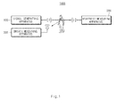
- FIG. 1 is a diagram showing a configuration of a driver monitoring system according to an exemplary embodiment of the present inventive concept.
- a driver monitoring system 1000 may include a signal generating apparatus 100, a heartbeat measuring apparatus 200, and a breath measuring apparatus 300.
- the signal generating apparatus 100 may generate and transmit a signal.
- the signal generating apparatus 100 may generate a signal having a predetermined signal property (e.g., center frequency, amplitude, or the like) and continuously emit the signal to the surroundings.
- the signal generating apparatus 100 may transmit the signal at periods of 1 to 5ms.
- the signal generating apparatus 100 may generate an ultra wideband (UWB) signal.
- UWB ultra wideband
- the signal generating apparatus 100 may be implemented in a form embedded in a steering wheel of a vehicle or a driver's seat sheet.
- the heartbeat measuring apparatus 200 may receive a signal penetrating a subject and measure a heartbeat of the subject. Specifically, the heartbeat measuring apparatus 200 may receive the signal penetrating the subject and measure the heartbeat of the subject using a variation of at least one of center frequency and amplitude of the received signal.
- the heartbeat measuring apparatus 200 may be positioned in a direction opposite to the signal generating apparatus 100 based on the subject. For example, the heartbeat measuring apparatus 200 may be positioned opposite to the signal generating apparatus 100 with respect to the subject. The reason is that the heartbeat measuring apparatus 200 may measure the heartbeat of the driver using the signal penetrating the heart of the driver. For example, when the signal generating apparatus 100 is positioned in the steering wheel, the heartbeat measuring apparatus 200 may be implemented in a form embedded in the driver's seat sheet. As another example, when the signal generating apparatus 100 is positioned in the driver's seat sheet, the heartbeat measuring apparatus 200 may be implemented in a form embedded in the steering wheel or the driver's seat sheet.
- the configurations of the signal generating apparatus 100 and the heartbeat measuring apparatus 200 only the configuration of transmitting the signal and the configuration of receiving the signal may be positioned in a direction opposite to each other (e.g., positioned opposite to each other with respect to the subject). In this case, the remaining configurations of the signal generating apparatus 100 and the heartbeat measuring apparatus 200 may be implemented in a physically single form.
- the breath measuring apparatus 300 may receive a signal reflected from the subject and measure breath or motion of the subject.
- the breath measuring apparatus 300 may measure the breath or the motion of the subject using a delayed amount of time of the signal reflected from the subject.
- the breath measuring apparatus 300 may compare a time of receiving the reflected signal with a time of transmitting the signal from the signal generating apparatus 100 to measure the delayed amount of time.
- the breath measuring apparatus 300 may be connected to the signal generating apparatus 100 to measure the delayed amount of time and may receive the time at which the signal is transmitted from the signal generating apparatus 100.
- the breath measuring apparatus 300 may measure the breath or the motion of the subject by monitoring the delayed amount of time.
- a chest of subject is expanded, such that a distance, in which the signal transmitted from the signal generating apparatus 100 is reflected from the subject and is then received by the breath measuring apparatus 300, becomes short.
- the delayed amount of time of the received signal may be decreased.
- the chest of subject is contracted, such that the distance, in which the signal transmitted from the signal generating apparatus 100 is reflected from the subject and is then received by the breath measuring apparatus 300, becomes long.
- the delayed amount of time of the received signal may be increased.
- the breath measuring apparatus 300 may measure the breath or the motion of the subject by continuously monitoring the delayed amount of time of the received signal.
- the breath measuring apparatus 300 among the configurations of the driver monitoring system 1000 may be omitted depending on an exemplary embodiment of the present inventive concept.
- FIG. 2 is a block diagram showing a configuration of a heartbeat measuring apparatus according to an exemplary embodiment of the present inventive concept.
- the heartbeat measuring apparatus 200 may include a receiver 210 and a measurer 220.
- the receiver 210 may receive a signal penetrating the subject among signals transmitted from the signal generating apparatus 100.
- the receiver 210 may include a low-noise amplifier for amplifying the received signal.
- the measurer 220 may measure the heartbeat of the subject using variation of at least one of center frequency and amplitude of the signal received by the receiver 210.
- the measurer 220 will be described in detail with reference to FIGS. 3 to 6 .
- FIG. 3 is a block diagram showing a detailed configuration of a measurer according to an exemplary embodiment of the present inventive concept.
- the measurer 220 may include a signal detector 221, a signal analyzer 222, and a heartbeat measurer 223.
- the signal detector 221 may detect a signal penetrating the heart of the subject among the signals received by the receiver 210. As an example of detecting the signal, a method using an attenuation amount of the signal will be described with reference to FIGS. 4A and 4B .
- FIGS. 4A and 4B are diagrams for describing a principle of detecting a signal according to an exemplary embodiment of the present inventive concept.
- a first path is a path penetrating the heart and a second path (path 2) is a path penetrating lungs. Because the heart is filled with liquid and the lungs are filled with gas, attenuation characteristics of the signal may be different when the signal penetrates two paths.
- Tables in FIG. 4B show attenuation characteristics of the signal when the signal penetrates the first path and the second path, respectively.
- a (signal) loss in the first path (through the heart) is 157.76dB and a (signal) loss in the second path (through the lung) is 80.16dB. That is, the path penetrating the heart and the path penetrating the lungs have very different signal attenuation degrees. Therefore, the signal detector 221 may classify the received signal into two groups depending on strength of the signal and may detect the group having a small strength of the signal as the signal penetrating the heart.
- time receiving the signal may be used.
- the signal detector 221 may detect an initially received signal among signals transmitted from the signal generating apparatus 100 at the same time.
- the initially received signal among the signals transmitted from the signal generating apparatus 100 may correspond to a signal having the shortest transmitting distance. That is, the initially received signal may correspond to a signal rectilinearly passing between the signal generating apparatus 100 and the heartbeat measuring apparatus 200. Referring to FIG. 4A . That is, the signal rectilinearly passing between the signal generating apparatus 100 and the heartbeat measuring apparatus 200 passes through the heart of the subject.
- the signal analyzer 222 may analyzes the signal detected by the signal detector 221. According to the exemplary embodiment of the present inventive concept, the signal analyzer 222 may analyze the signal in two ways.
- the signal analyzer 222 may analyze variation of at least one of center frequency and amplitude of the detected signal.
- the signal generating apparatus 100 may periodically transmit a signal having predetermined signal characteristics.
- the signal analyzer 222 may recognize the center frequency and amplitude of the signal transmitted from the signal generating apparatus 100 in advance, and may compares the center frequency and amplitude with center frequency and amplitude of the received signal to thereby analyze the variation of the center frequency and amplitude.
- the center frequency and amplitude of the UWB signal may be decreased.
- the signal analyzer 222 may analyze at least one of the center frequency and amplitude of the detected signal. That is, unlike the first exemplary embodiment in which the variation of the received signal is analyzed, the center frequency and amplitude of the received signal may be simply measured.
- the heartbeat measurer 223 may measure the heartbeat of the subject using the analyzed result of the signal analyzer 222. Specifically, the heartbeat measurer 223 may measure the heartbeat of the subject by monitoring the analyzed result of the signal analyzer 222. A principle of measuring the heartbeat by the heartbeat measurer 223 will be described with reference to FIGS. 5 and 6 .
- FIG. 5 is a diagram for describing a change in a center frequency of a signal penetrating a heart of a subject.
- the center frequency thereof may be decreased.
- a decreased amount of center frequency may be varied depending on a size of the heart.
- FIG. 5 corresponds to a result generated by performing an experiment on a water balloon in order to make an environment similar to the heart. Referring to FIG. 5 , it may be appreciated that the center frequency of the signal passing through the water balloon is decreased and as the size of the water balloon is increased, the decreased amount of center frequency is increased.
- the heart of the subject may be repeatedly contracted and relaxed. When being contracted, the size of the heart may be decreased, and when being relaxed, the size of the heart may be increased. That is, the heartbeat measurer 223 may determine whether or not the heart is contracted or relaxed by monitoring the center frequency of the received signal or the variation of the center frequency.
- FIG. 6 is a diagram for describing an amplitude change of the signal penetrating the heart of the subject.
- the amplitude thereof may be decreased.
- a decreased amount of amplitude may be varied depending on the size of the heart.
- FIG. 6 corresponds to a result generated by performing an experiment on a water balloon in order to make an environment similar to the heart. It may be appreciated from FIG. 6 that as the size of the water balloon is increased, the decreased amount of amplitude is increased.
- the heart of the subject may be repeatedly contracted and relaxed. When being contracted, the size of the heart may be decreased, and when being relaxed, the size of the heart may be increased. That is, the heartbeat measurer 223 may determine whether or not the heart is contracted or relaxed by monitoring the amplitude of the received signal or the variation of the amplitude.
- the heartbeat measuring apparatus may measure the heartbeat regardless of a location of the heart unlike a heartbeat measuring apparatus based on a reflective wave. Therefore, even though the subject moves during the heartbeat measurement, when the heart of the subject is located in a penetration path of the signal, the heartbeat may be measured.
- FIG. 7 is a flow chart for describing a heartbeat measuring method according to an exemplary embodiment of the present inventive concept.
- the heartbeat measuring apparatus 200 may firstly receive the signal penetrating the subject (S710).
- the signal penetrating the subject may be an ultra wideband (UWB) signal.
- UWB ultra wideband
- the heartbeat measuring apparatus 200 may measure the heartbeat of the subject using at least one of the center frequency and amplitude of the received signal (S720). Describing processes of measuring the heartbeat in detail, first, a signal penetrating the heart of the subject among the received signals may be detected. Here, when the signal is detected, the attenuation amount of signal may be used or the time receiving the signal may be used.
- the heartbeat measuring apparatus 200 may classify the received signal into two groups depending on strength of the signal and may detect the group having a small strength of the signal as the signal penetrating the heart.
- the heartbeat measuring apparatus 200 may detect an initially received signal among the received signals as the signal penetrating the heart. Because the initially received signal may be received through a straight line path, it may correspond to a signal having the shortest transmission distance. When it is configured such that the heart of the subject is positioned in the straight line path between the signal generating apparatus 100 and the heartbeat measuring apparatus 200, the initially received signal may be detected as the signal penetrating the heart.
- At least one of the center frequency and amplitude of the detected signal may be analyzed.
- the center frequency and amplitude may be analyzed or the variation of the center frequency and amplitude may be analyzed.
- the heartbeat of the subject may be measured by monitoring the analyzed result.
- the center frequency and amplitude thereof may be decreased.
- the decreased amount may be increased.
- a contraction or relaxation of the heart may be determined by continuously monitoring the analyzed result.
- the heartbeat may be measured regardless of the location of the heart. Therefore, even though the subject moves during the heartbeat measurement, when the heart of the subject is located in the penetration path of the signal, the heartbeat may be stably measured.
- the breath measurement together with the heartbeat measurement is possible, the state of the subject may be more accurately observed.
Landscapes
- Health & Medical Sciences (AREA)
- Life Sciences & Earth Sciences (AREA)
- Engineering & Computer Science (AREA)
- Animal Behavior & Ethology (AREA)
- Public Health (AREA)
- Veterinary Medicine (AREA)
- Biophysics (AREA)
- Pathology (AREA)
- Physics & Mathematics (AREA)
- Biomedical Technology (AREA)
- Heart & Thoracic Surgery (AREA)
- Medical Informatics (AREA)
- Molecular Biology (AREA)
- Surgery (AREA)
- General Health & Medical Sciences (AREA)
- Cardiology (AREA)
- Physiology (AREA)
- Nuclear Medicine, Radiotherapy & Molecular Imaging (AREA)
- Radiology & Medical Imaging (AREA)
- Pulmonology (AREA)
- Developmental Disabilities (AREA)
- Child & Adolescent Psychology (AREA)
- Educational Technology (AREA)
- Hospice & Palliative Care (AREA)
- Psychiatry (AREA)
- Psychology (AREA)
- Social Psychology (AREA)
- Measuring Pulse, Heart Rate, Blood Pressure Or Blood Flow (AREA)
Abstract
A heartbeat measuring apparatus includes a receiver and a measurer. The receiver is configured to receive ultra wideband (UWB) signals penetrating a subject. The measurer is configured to measure a heartbeat of the subject using at least one of center frequency and amplitude of the received UWB signals.
Description
- The present disclosure relates to a non-contact heartbeat measuring apparatus for measuring a heartbeat without contact a subject, a heartbeat measuring method, and a driver monitoring system for monitoring a driver using the same.
- In order to measure a heart state, a method in which electrodes contact a body to measure electrocardiogram has been generally used. However, the method of measuring the electrocardiogram has disadvantage in that the electrodes should be attached to the body and it is difficult for an ordinary person having no expert knowledge to use the method of measuring the electrocardiogram.
- In order to solve the above-mentioned problems, a method of measuring a heartbeat using radar reflected from a heart has also been developed. However, the method using the reflected wave, which is based on a change in a distance between a radar transceiver terminal and the heart, may be influenced by a motion of the subject.
- The present disclosure has been made to solve the above-mentioned problems occurring when using the prior art while advantages achieved by the prior art are maintained intact.
- An aspect of the present disclosure provides a heartbeat measuring apparatus capable of measuring a heartbeat regardless of a motion of a subject, a heartbeat measuring method, and a driver monitoring system.
- One aspect of the present disclosure relates to a heartbeat measuring apparatus including a receiver and a measurer. The receiver is configured to receive an ultra wideband (UWB) signals penetrating a subject. The measurer is configured to measure a heartbeat of the subject using at least one of center frequency and amplitude of the received UWB signals.
- The measurer may include a signal detector configured to detect a UWB signal penetrating a heart of the subject among the received UWB signals, a signal analyzer configured to analyze a variation of at least one of center frequency and amplitude of the detected UWB signal, and a heartbeat measurer configured to measure the heartbeat of the subject by monitoring the variation.
- The measurer may include a signal detector configured to detect the UWB signal penetrating the heart of the subject among the received UWB signals, a signal analyzer configured to analyze at least one of center frequency and amplitude of the detected UWB signal, and a heartbeat measurer configured to measure the heartbeat of the subject by monitoring the at least one of the center frequency and amplitude.
- The measurer may be configured to determine whether or not a heart of the subject is contracted or relaxed by monitoring the at least one of center frequency and amplitude of the received UWB signals.
- Another aspect of the present disclosure encompasses a driver monitoring system including a signal generating apparatus and a heartbeat measuring apparatus. The signal generating apparatus is configured to generate and transmit an ultra wideband (UWB) signal. The heartbeat measuring apparatus is configured to receive the UVB signal penetrating a subject and measure a heartbeat of the subject using at least one of center frequency and amplitude of the received UWB signal.
- The heartbeat measuring apparatus may be positioned opposite to the signal generating apparatus with respect to the subject.
- The driver monitoring system may further include a breath measuring apparatus configured to receive the UWB signal reflected from the subject and measure a breath or a motion of the subject using a delayed amount of time of the received UWB signal.
- The heartbeat measuring apparatus may be configured to determine whether or not the heart of the subject is contracted or relaxed by monitoring the at least one of center frequency and amplitude of the received UWB signal.
- Still another aspect of the present disclosure relates to a heartbeat measuring method including receiving ultra wideband (UWB) signals penetrating a subject. A heartbeat of the subject is measured using at least one of center frequency and amplitude of the received UWB signals.
- In the measuring of the heartbeat, a UWB signal penetrating a heart of the subject may be detected among the received UWB signals, a variation of at least one of center frequency and amplitude of the detected UWB signal may be analyzed, and the heartbeat of the subject may be measured by monitoring the variation.
- In the measuring of the heartbeat, an UWB signal penetrating a heart of the subject may be detected among the received UWB signals, at least one of center frequency and amplitude of the detected UWB signal may be analyzed, and the heartbeat of the subject may be measured by monitoring the at least one of center frequency and amplitude of the detected UWB signal.
- In the measuring of the heartbeat of the subject, it may be determined whether or not a heart of the subject is contracted or relaxed by monitoring the at least one of center frequency and amplitude of the received UWB signals
- The above and other objects, features and advantages of the present disclosure will be more apparent from the following detailed description taken in conjunction with the accompanying drawings.
-
FIG. 1 is a diagram showing a configuration of a driver monitoring system according to an exemplary embodiment of the present inventive concept. -
FIG. 2 is a block diagram showing a configuration of a heartbeat measuring apparatus according to an exemplary embodiment of the present inventive concept. -
FIG. 3 is a block diagram showing a detailed configuration of a measurer according to an exemplary embodiment of the present inventive concept. -
FIGS. 4A and 4B are diagrams for describing a principle of detecting a signal according to an exemplary embodiment of the present inventive concept. -
FIG. 5 is a diagram for describing a change in a center frequency of a signal penetrating a heart of a subject. -
FIG. 6 is a diagram for describing an amplitude change of a signal penetrating a heart of the subject. -
FIG. 7 is a flow chart for describing a heartbeat measuring method according to an exemplary embodiment of the present inventive concept. - Hereinafter, exemplary embodiments of the present inventive concept will be described in detail with reference to the accompanying drawings.
-
FIG. 1 is a diagram showing a configuration of a driver monitoring system according to an exemplary embodiment of the present inventive concept. - Referring to
FIG. 1 , adriver monitoring system 1000 may include asignal generating apparatus 100, aheartbeat measuring apparatus 200, and abreath measuring apparatus 300. - The
signal generating apparatus 100 may generate and transmit a signal. Thesignal generating apparatus 100 may generate a signal having a predetermined signal property (e.g., center frequency, amplitude, or the like) and continuously emit the signal to the surroundings. For example, thesignal generating apparatus 100 may transmit the signal at periods of 1 to 5ms. Particularly, thesignal generating apparatus 100 may generate an ultra wideband (UWB) signal. - Meanwhile, the
signal generating apparatus 100 may be implemented in a form embedded in a steering wheel of a vehicle or a driver's seat sheet. - The
heartbeat measuring apparatus 200 may receive a signal penetrating a subject and measure a heartbeat of the subject. Specifically, theheartbeat measuring apparatus 200 may receive the signal penetrating the subject and measure the heartbeat of the subject using a variation of at least one of center frequency and amplitude of the received signal. - The
heartbeat measuring apparatus 200 may be positioned in a direction opposite to thesignal generating apparatus 100 based on the subject. For example, theheartbeat measuring apparatus 200 may be positioned opposite to thesignal generating apparatus 100 with respect to the subject. The reason is that theheartbeat measuring apparatus 200 may measure the heartbeat of the driver using the signal penetrating the heart of the driver. For example, when thesignal generating apparatus 100 is positioned in the steering wheel, theheartbeat measuring apparatus 200 may be implemented in a form embedded in the driver's seat sheet. As another example, when thesignal generating apparatus 100 is positioned in the driver's seat sheet, theheartbeat measuring apparatus 200 may be implemented in a form embedded in the steering wheel or the driver's seat sheet. As another example, among the configurations of thesignal generating apparatus 100 and theheartbeat measuring apparatus 200, only the configuration of transmitting the signal and the configuration of receiving the signal may be positioned in a direction opposite to each other (e.g., positioned opposite to each other with respect to the subject). In this case, the remaining configurations of thesignal generating apparatus 100 and theheartbeat measuring apparatus 200 may be implemented in a physically single form. - The
breath measuring apparatus 300 may receive a signal reflected from the subject and measure breath or motion of the subject. Thebreath measuring apparatus 300 may measure the breath or the motion of the subject using a delayed amount of time of the signal reflected from the subject. Thebreath measuring apparatus 300 may compare a time of receiving the reflected signal with a time of transmitting the signal from thesignal generating apparatus 100 to measure the delayed amount of time. Thebreath measuring apparatus 300 may be connected to thesignal generating apparatus 100 to measure the delayed amount of time and may receive the time at which the signal is transmitted from thesignal generating apparatus 100. In addition, thebreath measuring apparatus 300 may measure the breath or the motion of the subject by monitoring the delayed amount of time. - That is, when the subject breathes in, a chest of subject is expanded, such that a distance, in which the signal transmitted from the
signal generating apparatus 100 is reflected from the subject and is then received by thebreath measuring apparatus 300, becomes short. As a result, the delayed amount of time of the received signal may be decreased. In addition, when the subject breathes out, the chest of subject is contracted, such that the distance, in which the signal transmitted from thesignal generating apparatus 100 is reflected from the subject and is then received by thebreath measuring apparatus 300, becomes long. As a result, the delayed amount of time of the received signal may be increased. Thebreath measuring apparatus 300 may measure the breath or the motion of the subject by continuously monitoring the delayed amount of time of the received signal. - Meanwhile, the
breath measuring apparatus 300 among the configurations of thedriver monitoring system 1000 may be omitted depending on an exemplary embodiment of the present inventive concept. -
FIG. 2 is a block diagram showing a configuration of a heartbeat measuring apparatus according to an exemplary embodiment of the present inventive concept. - Referring to
FIG. 2 , theheartbeat measuring apparatus 200 may include areceiver 210 and ameasurer 220. - The
receiver 210 may receive a signal penetrating the subject among signals transmitted from thesignal generating apparatus 100. Thereceiver 210 may include a low-noise amplifier for amplifying the received signal. - The
measurer 220 may measure the heartbeat of the subject using variation of at least one of center frequency and amplitude of the signal received by thereceiver 210. Themeasurer 220 will be described in detail with reference toFIGS. 3 to 6 . -
FIG. 3 is a block diagram showing a detailed configuration of a measurer according to an exemplary embodiment of the present inventive concept. - Referring to
FIG. 3 , themeasurer 220 may include asignal detector 221, asignal analyzer 222, and aheartbeat measurer 223. - The
signal detector 221 may detect a signal penetrating the heart of the subject among the signals received by thereceiver 210. As an example of detecting the signal, a method using an attenuation amount of the signal will be described with reference toFIGS. 4A and 4B . -
FIGS. 4A and 4B are diagrams for describing a principle of detecting a signal according to an exemplary embodiment of the present inventive concept. - Referring to
FIG. 4A , when the signal penetrates the body, it may penetrate the body through two paths. A first path (path 1) is a path penetrating the heart and a second path (path 2) is a path penetrating lungs. Because the heart is filled with liquid and the lungs are filled with gas, attenuation characteristics of the signal may be different when the signal penetrates two paths. - Tables in
FIG. 4B show attenuation characteristics of the signal when the signal penetrates the first path and the second path, respectively. Referring toFIG. 4B , it may be appreciated that a (signal) loss in the first path (through the heart) is 157.76dB and a (signal) loss in the second path (through the lung) is 80.16dB. That is, the path penetrating the heart and the path penetrating the lungs have very different signal attenuation degrees. Therefore, thesignal detector 221 may classify the received signal into two groups depending on strength of the signal and may detect the group having a small strength of the signal as the signal penetrating the heart. - As another example of detecting the signal, time receiving the signal may be used. Specifically, the
signal detector 221 may detect an initially received signal among signals transmitted from thesignal generating apparatus 100 at the same time. The initially received signal among the signals transmitted from thesignal generating apparatus 100 may correspond to a signal having the shortest transmitting distance. That is, the initially received signal may correspond to a signal rectilinearly passing between thesignal generating apparatus 100 and theheartbeat measuring apparatus 200. Referring toFIG. 4A . That is, the signal rectilinearly passing between thesignal generating apparatus 100 and theheartbeat measuring apparatus 200 passes through the heart of the subject. - The
signal analyzer 222 may analyzes the signal detected by thesignal detector 221. According to the exemplary embodiment of the present inventive concept, thesignal analyzer 222 may analyze the signal in two ways. - According to a first exemplary embodiment of the present inventive concept, the
signal analyzer 222 may analyze variation of at least one of center frequency and amplitude of the detected signal. Thesignal generating apparatus 100 may periodically transmit a signal having predetermined signal characteristics. In addition, thesignal analyzer 222 may recognize the center frequency and amplitude of the signal transmitted from thesignal generating apparatus 100 in advance, and may compares the center frequency and amplitude with center frequency and amplitude of the received signal to thereby analyze the variation of the center frequency and amplitude. When the UWB signal penetrates the heart of the subject, the center frequency and amplitude of the UWB signal may be decreased. - According to a second exemplary embodiment of the present inventive concept, the
signal analyzer 222 may analyze at least one of the center frequency and amplitude of the detected signal. That is, unlike the first exemplary embodiment in which the variation of the received signal is analyzed, the center frequency and amplitude of the received signal may be simply measured. - The
heartbeat measurer 223 may measure the heartbeat of the subject using the analyzed result of thesignal analyzer 222. Specifically, theheartbeat measurer 223 may measure the heartbeat of the subject by monitoring the analyzed result of thesignal analyzer 222. A principle of measuring the heartbeat by theheartbeat measurer 223 will be described with reference toFIGS. 5 and6 . -
FIG. 5 is a diagram for describing a change in a center frequency of a signal penetrating a heart of a subject. - As the signal transmitted from the
signal generating apparatus 100 penetrates the heart of the subject, the center frequency thereof may be decreased. In addition, a decreased amount of center frequency may be varied depending on a size of the heart. - A relationship between the size of the heart and the decreased amount of center frequency may be confirmed from the
FIG. 5. FIG. 5 corresponds to a result generated by performing an experiment on a water balloon in order to make an environment similar to the heart. Referring toFIG. 5 , it may be appreciated that the center frequency of the signal passing through the water balloon is decreased and as the size of the water balloon is increased, the decreased amount of center frequency is increased. - The heart of the subject may be repeatedly contracted and relaxed. When being contracted, the size of the heart may be decreased, and when being relaxed, the size of the heart may be increased. That is, the
heartbeat measurer 223 may determine whether or not the heart is contracted or relaxed by monitoring the center frequency of the received signal or the variation of the center frequency. -
FIG. 6 is a diagram for describing an amplitude change of the signal penetrating the heart of the subject. - As the signal transmitted from the
signal generating apparatus 100 penetrates the heart of the subject, the amplitude thereof may be decreased. In addition, a decreased amount of amplitude may be varied depending on the size of the heart. - The decreased amount of amplitude according to the size of the heart may be confirmed from
FIG. 6 . Similar toFIG. 5 ,FIG. 6 corresponds to a result generated by performing an experiment on a water balloon in order to make an environment similar to the heart. It may be appreciated fromFIG. 6 that as the size of the water balloon is increased, the decreased amount of amplitude is increased. - The heart of the subject may be repeatedly contracted and relaxed. When being contracted, the size of the heart may be decreased, and when being relaxed, the size of the heart may be increased. That is, the
heartbeat measurer 223 may determine whether or not the heart is contracted or relaxed by monitoring the amplitude of the received signal or the variation of the amplitude. - The heartbeat measuring apparatus according to an exemplary embodiment of the present inventive concept may measure the heartbeat regardless of a location of the heart unlike a heartbeat measuring apparatus based on a reflective wave. Therefore, even though the subject moves during the heartbeat measurement, when the heart of the subject is located in a penetration path of the signal, the heartbeat may be measured.
-
FIG. 7 is a flow chart for describing a heartbeat measuring method according to an exemplary embodiment of the present inventive concept. - Referring to
FIG. 7 , theheartbeat measuring apparatus 200 may firstly receive the signal penetrating the subject (S710). Here, the signal penetrating the subject may be an ultra wideband (UWB) signal. - In addition, the
heartbeat measuring apparatus 200 may measure the heartbeat of the subject using at least one of the center frequency and amplitude of the received signal (S720). Describing processes of measuring the heartbeat in detail, first, a signal penetrating the heart of the subject among the received signals may be detected. Here, when the signal is detected, the attenuation amount of signal may be used or the time receiving the signal may be used. - The path penetrating the heart and the path penetrating the lungs have very different signal attenuation degrees. Therefore, the
heartbeat measuring apparatus 200 may classify the received signal into two groups depending on strength of the signal and may detect the group having a small strength of the signal as the signal penetrating the heart. - Alternatively, the
heartbeat measuring apparatus 200 may detect an initially received signal among the received signals as the signal penetrating the heart. Because the initially received signal may be received through a straight line path, it may correspond to a signal having the shortest transmission distance. When it is configured such that the heart of the subject is positioned in the straight line path between thesignal generating apparatus 100 and theheartbeat measuring apparatus 200, the initially received signal may be detected as the signal penetrating the heart. - In addition, at least one of the center frequency and amplitude of the detected signal may be analyzed. When the detected signal is analyzed, the center frequency and amplitude may be analyzed or the variation of the center frequency and amplitude may be analyzed.
- In addition, the heartbeat of the subject may be measured by monitoring the analyzed result. When the UWB signal penetrating the heart is received, the center frequency and amplitude thereof may be decreased. In addition, as the size of the heart is increased, the decreased amount may be increased. As a result, a contraction or relaxation of the heart may be determined by continuously monitoring the analyzed result.
- As described above, according to exemplary embodiments of the present inventive concept, the heartbeat may be measured regardless of the location of the heart. Therefore, even though the subject moves during the heartbeat measurement, when the heart of the subject is located in the penetration path of the signal, the heartbeat may be stably measured.
- Further, because the breath measurement together with the heartbeat measurement is possible, the state of the subject may be more accurately observed.
- Although some embodiments of the present inventive concept have been disclosed for illustrative purposes, those skilled in the art will appreciate that various modifications, additions and substitutions are possible, without departing from the scope and spirit of the disclosure as disclosed in the accompanying claims. Accordingly, such modifications, additions and substitutions should also be understood to fall within the scope of the present inventive concept.
-
- 100:
- SIGNAL GENERATING APPARATUS
- 200:
- HEARTBEAT MEASURING APPARATUS
- 210:
- RECEIVER
- 220:
- MEASURER
- 221:
- SIGNAL DETECTOR
- 222:
- SIGNAL ANALYZER
- 223:
- HEARTBEAT MEASURER
- 300:
- BREATH MEASURING APPARATUS
Claims (12)
- A heartbeat measuring apparatus, comprising:a receiver configured to receive ultra wideband (UWB) signals penetrating a subject; anda measurer configured to measure a heartbeat of the subject using at least one of center frequency and amplitude of the received UWB signals.
- The heartbeat measuring apparatus according to claim 1, wherein the measurer includes:a signal detector configured to detect a UWB signal penetrating a heart of the subject among the received UWB signals;a signal analyzer configured to analyze a variation of at least one of center frequency and amplitude of the detected UWB signal; anda heartbeat measurer configured to measure the heartbeat of the subject by monitoring the variation.
- The heartbeat measuring apparatus according to claim 1, wherein the measurer includes:a signal detector configured to detect the UWB signal penetrating a heart of the subject among the received UWB signals;a signal analyzer configured to analyze at least one of center frequency and amplitude of the detected UWB signal; anda heartbeat measurer configured to measure the heartbeat of the subject by monitoring the at least one of center frequency and amplitude of the detected UWB signal.
- A driver monitoring system, comprising:a signal generating apparatus configured to generate and transmit an ultra wideband (UWB) signal; anda heartbeat measuring apparatus configured to receive the UVB signal penetrating a subject and measure a heartbeat of the subject using at least one of center frequency and amplitude of the received UWB signal.
- The driver monitoring system according to claim 4, wherein the heartbeat measuring apparatus is positioned opposite to the signal generating apparatus with respect to the subject.
- The driver monitoring system according to claim 4, further comprising a breath measuring apparatus configured to receive the UWB signal reflected from the subject and measure a breath or a motion of the subject using a delayed amount of time of the received UWB signal.
- A heartbeat measuring method, comprising:receiving ultra wideband (UWB) signals penetrating a subject; andmeasuring a heartbeat of the subject using at least one of center frequency and amplitude of the received UWB signals.
- The heartbeat measuring method according to claim 7, wherein the measuring of the heartbeat includes:detecting a UWB signal penetrating a heart of the subject among the received UWB signals;analyzing a variation of at least one of center frequency and amplitude of the detected UWB signal; andmeasuring the heartbeat of the subject by monitoring the variation.
- The heartbeat measuring method according to claim 7, wherein the measuring of the heartbeat includes:detecting a UWB signal penetrating a heart of the subject among the received UWB signals;analyzing at least one of center frequency and amplitude of the detected UWB signal; andmeasuring the heartbeat of the subject by monitoring the at least one of center frequency and amplitude of the detected UWB signal.
- The heartbeat measuring apparatus according to claim 1, wherein the measurer is configured to determine whether or not a heart of the subject is contracted or relaxed by monitoring the at least one of center frequency and amplitude of the received UWB signals.
- The driver monitoring system according to claim 4, wherein the heartbeat measuring apparatus is configured to determine whether or not the heart of the subject is contracted or relaxed by monitoring the at least one of center frequency and amplitude of the received UWB signal.
- The heartbeat measuring method according to claim 7, wherein the measuring of the heartbeat of the subject includes determining whether or not a heart of the subject is contracted or relaxed by monitoring the at least one of center frequency and amplitude of the received UWB signals.
Applications Claiming Priority (1)
| Application Number | Priority Date | Filing Date | Title |
|---|---|---|---|
| KR20130158473 | 2013-12-18 |
Publications (1)
| Publication Number | Publication Date |
|---|---|
| EP2886051A1 true EP2886051A1 (en) | 2015-06-24 |
Family
ID=51730313
Family Applications (1)
| Application Number | Title | Priority Date | Filing Date |
|---|---|---|---|
| EP14186894.3A Withdrawn EP2886051A1 (en) | 2013-12-18 | 2014-09-29 | Heartbeat measuring apparatus, heartbeat measuring method and driver monitoring system |
Country Status (4)
| Country | Link |
|---|---|
| US (1) | US20150164364A1 (en) |
| EP (1) | EP2886051A1 (en) |
| JP (1) | JP6549359B2 (en) |
| CN (1) | CN104720769A (en) |
Cited By (5)
| Publication number | Priority date | Publication date | Assignee | Title |
|---|---|---|---|---|
| EP3407778A4 (en) * | 2016-01-27 | 2019-09-18 | Life Detection Technologies, Inc. | SYSTEMS AND METHODS FOR DETECTING PHYSICAL CHANGE WITHOUT PHYSICAL CONTACT |
| US11253163B2 (en) | 2016-01-27 | 2022-02-22 | Life Detection Technologies, Inc. | Systems and methods for detecting physical changes without physical contact |
| US12310709B2 (en) | 2016-01-27 | 2025-05-27 | Life Detection Technologies, Inc. | Computation of parameters of a body using an electric field |
| US12310710B2 (en) | 2016-01-27 | 2025-05-27 | Life Detection Technologies, Inc. | Computation of parameters of a body using an electric field |
| US12350029B2 (en) | 2016-01-27 | 2025-07-08 | Life Detection Technologies, Inc. | Computation of parameters of a body using an electric field |
Families Citing this family (6)
| Publication number | Priority date | Publication date | Assignee | Title |
|---|---|---|---|---|
| KR101571494B1 (en) * | 2014-08-20 | 2015-11-25 | 연세대학교 산학협력단 | System for monitoring user utilizing pulse signal |
| KR101688434B1 (en) * | 2015-08-25 | 2016-12-23 | 재단법인대구경북과학기술원 | Image acquisition apparatus and method |
| KR101766729B1 (en) * | 2016-04-04 | 2017-08-23 | 주식회사 서연전자 | Apparatus for receiving a a bio-signal |
| WO2018189800A1 (en) * | 2017-04-11 | 2018-10-18 | 東京コスモス電機株式会社 | Biological information detection system and biological information detection method |
| CN110573069B (en) * | 2017-04-19 | 2023-01-03 | 学校法人关西大学 | Biological information estimation device |
| CN114601432B (en) * | 2022-01-28 | 2024-10-11 | 中国第一汽车股份有限公司 | Vehicle-mounted human body information acquisition method and device and vehicle |
Citations (4)
| Publication number | Priority date | Publication date | Assignee | Title |
|---|---|---|---|---|
| US5766208A (en) * | 1994-08-09 | 1998-06-16 | The Regents Of The University Of California | Body monitoring and imaging apparatus and method |
| US20070055164A1 (en) * | 2005-09-02 | 2007-03-08 | Industrial Technology Research Institute | Physiological status monitoring system and method |
| EP2157665A1 (en) * | 2008-08-22 | 2010-02-24 | Industrial Technology Research Institute | UWB antenna and detection apparatus for transportation means |
| WO2013096872A1 (en) * | 2011-12-21 | 2013-06-27 | Lifewave, Inc. | Fetal monitoring device and methods |
Family Cites Families (14)
| Publication number | Priority date | Publication date | Assignee | Title |
|---|---|---|---|---|
| US7766383B2 (en) * | 1998-11-17 | 2010-08-03 | Automotive Technologies International, Inc. | Vehicular component adjustment system and method |
| US6454711B1 (en) * | 1999-04-23 | 2002-09-24 | The Regents Of The University Of California | Microwave hemorrhagic stroke detector |
| US7389136B2 (en) * | 2002-12-04 | 2008-06-17 | Ge Medical Systems Global Technology Company, Llc | Method and system using a non-electrical sensor for gating |
| US20040249257A1 (en) * | 2003-06-04 | 2004-12-09 | Tupin Joe Paul | Article of manufacture for extracting physiological data using ultra-wideband radar and improved signal processing techniques |
| EP2101641A2 (en) * | 2006-12-07 | 2009-09-23 | Philometron, Inc. | Platform for detection of tissue content and/or structural changes with closed-loop control in mammalian organisms |
| US7898455B2 (en) * | 2007-07-17 | 2011-03-01 | Rosenbury Erwin T | Handheld instrument capable of measuring heartbeat and breathing motion at a distance |
| JP5131657B2 (en) * | 2007-09-05 | 2013-01-30 | 公益財団法人北九州産業学術推進機構 | Respiration monitoring method and apparatus |
| RU2369323C1 (en) * | 2008-02-20 | 2009-10-10 | Игорь Яковлевич Иммореев | Impulse superwide-band sensor |
| US20100152600A1 (en) * | 2008-04-03 | 2010-06-17 | Kai Sensors, Inc. | Non-contact physiologic motion sensors and methods for use |
| JP6081355B2 (en) * | 2010-07-21 | 2017-02-15 | キマ メディカル テクノロジーズ リミテッド | Embedded radio frequency sensor |
| EP2417908A1 (en) * | 2010-08-12 | 2012-02-15 | Philips Intellectual Property & Standards GmbH | Device, system and method for measuring vital signs |
| DE102011083408A1 (en) * | 2011-09-26 | 2013-03-28 | Siemens Aktiengesellschaft | An imaging method and apparatus for displaying vessels or organs in an examination area of a patient |
| JP2013153783A (en) * | 2012-01-26 | 2013-08-15 | Toyota Infotechnology Center Co Ltd | Heartbeat detector and heartbeat detection method |
| US9532735B2 (en) * | 2013-10-23 | 2017-01-03 | King Abdullah University Of Science And Technology | Apparatus and method for wireless monitoring using ultra-wideband frequencies |
-
2014
- 2014-08-11 JP JP2014163336A patent/JP6549359B2/en active Active
- 2014-09-29 EP EP14186894.3A patent/EP2886051A1/en not_active Withdrawn
- 2014-10-14 US US14/514,231 patent/US20150164364A1/en not_active Abandoned
- 2014-10-17 CN CN201410553093.0A patent/CN104720769A/en active Pending
Patent Citations (4)
| Publication number | Priority date | Publication date | Assignee | Title |
|---|---|---|---|---|
| US5766208A (en) * | 1994-08-09 | 1998-06-16 | The Regents Of The University Of California | Body monitoring and imaging apparatus and method |
| US20070055164A1 (en) * | 2005-09-02 | 2007-03-08 | Industrial Technology Research Institute | Physiological status monitoring system and method |
| EP2157665A1 (en) * | 2008-08-22 | 2010-02-24 | Industrial Technology Research Institute | UWB antenna and detection apparatus for transportation means |
| WO2013096872A1 (en) * | 2011-12-21 | 2013-06-27 | Lifewave, Inc. | Fetal monitoring device and methods |
Non-Patent Citations (1)
| Title |
|---|
| CHRISTINE N. PAULSON ET AL: "<title>Ultra-wideband radar methods and techniques of medical sensing and imaging</title>", PROCEEDINGS OF SPIE, vol. 6007, 9 November 2005 (2005-11-09), pages 60070L, XP055065827, ISSN: 0277-786X, DOI: 10.1117/12.630004 * |
Cited By (8)
| Publication number | Priority date | Publication date | Assignee | Title |
|---|---|---|---|---|
| EP3407778A4 (en) * | 2016-01-27 | 2019-09-18 | Life Detection Technologies, Inc. | SYSTEMS AND METHODS FOR DETECTING PHYSICAL CHANGE WITHOUT PHYSICAL CONTACT |
| US11253163B2 (en) | 2016-01-27 | 2022-02-22 | Life Detection Technologies, Inc. | Systems and methods for detecting physical changes without physical contact |
| US11523745B2 (en) | 2016-01-27 | 2022-12-13 | Life Detection Technologies, Inc. | Systems and methods for detecting physical changes without physical contact |
| US11684283B2 (en) | 2016-01-27 | 2023-06-27 | Life Detection Technologies, Inc. | Systems and methods for detecting physical changes without physical contact |
| US11896357B2 (en) | 2016-01-27 | 2024-02-13 | Life Detection Technologies, Inc. | Systems and methods for detecting physical changes without physical contact |
| US12310709B2 (en) | 2016-01-27 | 2025-05-27 | Life Detection Technologies, Inc. | Computation of parameters of a body using an electric field |
| US12310710B2 (en) | 2016-01-27 | 2025-05-27 | Life Detection Technologies, Inc. | Computation of parameters of a body using an electric field |
| US12350029B2 (en) | 2016-01-27 | 2025-07-08 | Life Detection Technologies, Inc. | Computation of parameters of a body using an electric field |
Also Published As
| Publication number | Publication date |
|---|---|
| JP2015116473A (en) | 2015-06-25 |
| CN104720769A (en) | 2015-06-24 |
| US20150164364A1 (en) | 2015-06-18 |
| JP6549359B2 (en) | 2019-07-24 |
Similar Documents
| Publication | Publication Date | Title |
|---|---|---|
| US20150164364A1 (en) | Heartbeat measuring apparatus, heartbeat measuring method and driver monitoring system | |
| JP5848469B1 (en) | Biological condition detection device | |
| KR101571500B1 (en) | Apparatus for measuring bio signal using bandwidth of pulse signal, and system for monitoring user comprising the same | |
| EP3424418B1 (en) | A method and a system for detecting a vital sign of a subject | |
| US9713434B2 (en) | Microwave contactless heart rate sensor | |
| JP5131744B2 (en) | Biological vibration frequency detection device and vehicle | |
| JP2019132850A (en) | program | |
| US11045145B2 (en) | Buckle and on-vehicle system | |
| US11259715B2 (en) | Monitoring and diagnostics systems and methods | |
| CN106999090B (en) | Apparatus and method for estimating the value of a physiological property | |
| US20170143232A1 (en) | Sweat and heart rate determination system, sweat and heart rate determination apparatus, and sweat and heart rate determination method | |
| JP6222454B2 (en) | Biological information measuring apparatus and biological information measuring method | |
| Gigie et al. | Novel approach for vibration detection using indented radar | |
| US20190374126A1 (en) | Method and device for measuring biometric signal by using radar | |
| Alizadeh et al. | Remote heart rate sensing with mm-wave radar | |
| TW201418712A (en) | Imaging method and system for detecting motion state of object by using ultra-wideband radar | |
| US12102476B2 (en) | Contact-free acoustic monitoring and measurement system | |
| KR100888010B1 (en) | Remote biological signal measurement radar sensor using two frequencies | |
| Rong et al. | Novel respiration-free heartbeat detection algorithm using millimeter-wave radar | |
| Al-Wahedi et al. | Wireless monitoring of respiration and heart rates using software-defined-radio | |
| KR101995966B1 (en) | Apparatus and method measuring real respiration signal based on the frequency analysis and time analysis | |
| US20240302495A1 (en) | Radar based range determination and validation | |
| JP2019050848A5 (en) | ||
| JP2016135233A (en) | Organism status detector | |
| Lee et al. | Heart rate tracking using a Doppler radar with the reassigned joint time-frequency transform |
Legal Events
| Date | Code | Title | Description |
|---|---|---|---|
| PUAI | Public reference made under article 153(3) epc to a published international application that has entered the european phase |
Free format text: ORIGINAL CODE: 0009012 |
|
| 17P | Request for examination filed |
Effective date: 20140929 |
|
| AK | Designated contracting states |
Kind code of ref document: A1 Designated state(s): AL AT BE BG CH CY CZ DE DK EE ES FI FR GB GR HR HU IE IS IT LI LT LU LV MC MK MT NL NO PL PT RO RS SE SI SK SM TR |
|
| AX | Request for extension of the european patent |
Extension state: BA ME |
|
| STAA | Information on the status of an ep patent application or granted ep patent |
Free format text: STATUS: THE APPLICATION IS DEEMED TO BE WITHDRAWN |
|
| 18D | Application deemed to be withdrawn |
Effective date: 20160105 |