EP2886036A1 - Endoscope - Google Patents
Endoscope Download PDFInfo
- Publication number
- EP2886036A1 EP2886036A1 EP13879618.0A EP13879618A EP2886036A1 EP 2886036 A1 EP2886036 A1 EP 2886036A1 EP 13879618 A EP13879618 A EP 13879618A EP 2886036 A1 EP2886036 A1 EP 2886036A1
- Authority
- EP
- European Patent Office
- Prior art keywords
- wire
- bending portion
- bending
- regulation
- bent
- Prior art date
- Legal status (The legal status is an assumption and is not a legal conclusion. Google has not performed a legal analysis and makes no representation as to the accuracy of the status listed.)
- Withdrawn
Links
Images






Classifications
-
- A—HUMAN NECESSITIES
- A61—MEDICAL OR VETERINARY SCIENCE; HYGIENE
- A61B—DIAGNOSIS; SURGERY; IDENTIFICATION
- A61B1/00—Instruments for performing medical examinations of the interior of cavities or tubes of the body by visual or photographical inspection, e.g. endoscopes; Illuminating arrangements therefor
- A61B1/005—Flexible endoscopes
- A61B1/0051—Flexible endoscopes with controlled bending of insertion part
- A61B1/0057—Constructional details of force transmission elements, e.g. control wires
-
- A—HUMAN NECESSITIES
- A61—MEDICAL OR VETERINARY SCIENCE; HYGIENE
- A61B—DIAGNOSIS; SURGERY; IDENTIFICATION
- A61B1/00—Instruments for performing medical examinations of the interior of cavities or tubes of the body by visual or photographical inspection, e.g. endoscopes; Illuminating arrangements therefor
- A61B1/005—Flexible endoscopes
- A61B1/0051—Flexible endoscopes with controlled bending of insertion part
- A61B1/0055—Constructional details of insertion parts, e.g. vertebral elements
-
- A—HUMAN NECESSITIES
- A61—MEDICAL OR VETERINARY SCIENCE; HYGIENE
- A61B—DIAGNOSIS; SURGERY; IDENTIFICATION
- A61B1/00—Instruments for performing medical examinations of the interior of cavities or tubes of the body by visual or photographical inspection, e.g. endoscopes; Illuminating arrangements therefor
- A61B1/005—Flexible endoscopes
- A61B1/0051—Flexible endoscopes with controlled bending of insertion part
- A61B1/0055—Constructional details of insertion parts, e.g. vertebral elements
- A61B1/0056—Constructional details of insertion parts, e.g. vertebral elements the insertion parts being asymmetric, e.g. for unilateral bending mechanisms
-
- A—HUMAN NECESSITIES
- A61—MEDICAL OR VETERINARY SCIENCE; HYGIENE
- A61B—DIAGNOSIS; SURGERY; IDENTIFICATION
- A61B1/00—Instruments for performing medical examinations of the interior of cavities or tubes of the body by visual or photographical inspection, e.g. endoscopes; Illuminating arrangements therefor
- A61B1/005—Flexible endoscopes
- A61B1/008—Articulations
-
- A—HUMAN NECESSITIES
- A61—MEDICAL OR VETERINARY SCIENCE; HYGIENE
- A61B—DIAGNOSIS; SURGERY; IDENTIFICATION
- A61B1/00—Instruments for performing medical examinations of the interior of cavities or tubes of the body by visual or photographical inspection, e.g. endoscopes; Illuminating arrangements therefor
- A61B1/04—Instruments for performing medical examinations of the interior of cavities or tubes of the body by visual or photographical inspection, e.g. endoscopes; Illuminating arrangements therefor combined with photographic or television appliances
- A61B1/05—Instruments for performing medical examinations of the interior of cavities or tubes of the body by visual or photographical inspection, e.g. endoscopes; Illuminating arrangements therefor combined with photographic or television appliances characterised by the image sensor, e.g. camera, being in the distal end portion
-
- G—PHYSICS
- G02—OPTICS
- G02B—OPTICAL ELEMENTS, SYSTEMS OR APPARATUS
- G02B23/00—Telescopes, e.g. binoculars; Periscopes; Instruments for viewing the inside of hollow bodies; Viewfinders; Optical aiming or sighting devices
- G02B23/24—Instruments or systems for viewing the inside of hollow bodies, e.g. fibrescopes
- G02B23/26—Instruments or systems for viewing the inside of hollow bodies, e.g. fibrescopes using light guides
Definitions
- the present invention relates to an endoscope having a bending portion which can be bent in an S-shape.
- Patent Literature 1 discloses an endoscope. This endoscope has a first bending portion provided at the distal end of an insertion portion, a second bending portion which is provided at the proximal end of the insertion portion and which is coupled to the first bending portion, and an operation portion which operates the first bending portion. The second bending portion is bent by external force.
- Patent Literature 2 discloses another endoscope.
- a bending portion of the endoscope is bent preferentially from the distal end portion side of the bending portion.
- Patent Literature 3 discloses yet another endoscope.
- This endoscope has a first bending portion, a second bending portion coupled to the proximal end portion of the first bending portion, a first operation portion which operates the first bending portion, and a second operation portion which operates the second bending portion.
- the endoscope has the operation portions which respectively operate the bending portions.
- the second bending portion is only bent by the external force.
- the bending portion is bent preferentially from the distal end portion side of the bending portion.
- Patent Literature 3 the first operation portion and the second operation portion are provided.
- the operator bends the bending portion in an S-shape, each of the first and second operation portions needs to be operated, thus the operation is complicated.
- the present invention has been made in view of these circumstances, and an object of the invention is to provide an endoscope in which a bending portion can be readily bent in an S-shape by one operation portion.
- An aspect of an endoscope of the present invention includes distal rigid portion comprising an imaging unit configured to image an observation target; a bending portion comprising a first bending portion coupled to the distal rigid portion and a second bending portion coupled to the proximal end portion of the first bending portion; a flexible tube portion coupled to the proximal end portion of the second bending portion; an operation wire which is connected to the distal rigid portion and which is inserted through the first bending portion, the second bending portion, and the flexible tube portion; a wire guide member comprising a distal end fixed to the inside of the distal end of the second bending portion, the wire guide member being inserted through the second bending portion and the flexible tube portion, the wire guide member guiding the operation wire when the operation wire is inserted through the wire guide member; a bending operation portion which is connected to the operation wire and which bends and operates the first bending portion when the bending operation portion pulls the operation wire; and a regulation wire, the regulation wire being longer than the bending portion, the regulation wire being
- the present invention is able to provide an endoscope in which a bending portion can be readily bent in an S-shape by one operation portion.
- FIG. 1 A first embodiment is described with reference to FIG. 1 , FIG. 2 , FIG. 3A, FIG. 3B , FIG. 3C, FIG. 4 , FIG. 5A, FIG. 5B , FIG. 6A , and FIG. 6B .
- wire guide member 101 is not shown in, for example, FIG. 5A , some components are not shown for simplicity in some of the drawings.
- the longitudinal direction of an insertion portion 10 the longitudinal direction of a bending portion 23, and the axial direction of the wire guide member 101 are the same direction.
- an endoscope 1 has the elongate insertion portion 10 to be inserted into, for example, a body cavity of a patient, and an operation portion 60 which is coupled to the proximal end portion of the insertion portion 10 and which operates the endoscope 1.
- the insertion portion 10 has a distal rigid portion 21, a bending portion 23, and a flexible tube portion 25 from the distal end portion side of the insertion portion 10 to the proximal end portion side of the insertion portion 10.
- the proximal end portion of the distal rigid portion 21 is coupled to the distal end portion of the bending portion 23, and the proximal end portion of the bending portion 23 is coupled to the distal end portion of the flexible tube portion 25.
- the distal rigid portion 21 functions as the distal end of the endoscope 1 and the distal end of the insertion portion 10, and is rigid.
- the distal rigid portion 21 has an unshown imaging unit to image an observation target.
- the bending portion 23 will be described later.
- the flexible tube portion 25 has desired flexibility. Therefore, the flexible tube portion 25 is bent by external force.
- the flexible tube portion 25 is a tubular member extending from a later-described main body portion 61 in the operation portion 60.
- the operation portion 60 has the main body portion 61 from which the flexible tube portion 25 extends, a grasping portion 63 which is coupled to the proximal end portion of the main body portion 61 and which is grasped by an operator to operate the endoscope 1, and a universal cord 65 connected to the grasping portion 63.
- the main body portion 61 has a treatment tool insertion opening 61a.
- the treatment tool insertion opening 61a is coupled to the proximal end portion of an unshown treatment tool insertion channel.
- the treatment tool insertion channel is provided from the flexible tube portion 25 to the distal rigid portion 21 inside the insertion portion 10.
- the treatment tool insertion opening 61a is an insertion opening to insert an unshown endoscope treatment tool into the treatment tool insertion channel.
- the unshown endoscope treatment tool is inserted into the treatment tool insertion channel from the treatment tool insertion opening 61a, and pressed to the side of the distal rigid portion 21.
- the unshown endoscope treatment tool is then projected from an unshown distal opening portion of the treatment tool insertion channel provided in the distal rigid portion 21.
- the grasping portion 63 has a bending operation portion 67 which bends and operates the bending portion 23.
- the bending operation portion 67 has a horizontal bending operation knob 67a which is operated to horizontally bend the bending portion 23, and a vertical bending operation knob 67b which is operated to vertically bend the bending portion 23.
- the bending operation portion 67 further has a fixing knob 67c which fixes the position of the bent bending portion 23.
- the horizontal bending operation knob 67a is connected to an unshown horizontal bending operation mechanism driven by the horizontal bending operation knob 67a.
- the vertical bending operation knob 67b is connected to an unshown vertical bending operation mechanism driven by the vertical bending operation knob 67b.
- the vertical bending operation mechanism and the horizontal bending operation mechanism are provided in the operation portion 60.
- the horizontal bending operation mechanism is connected to the proximal end portion of a later-described operation wire 50 inserted through the flexible tube portion 25 and the bending portion 23. As shown in FIG. 2 , the distal end portion of this operation wire 50 is connected to the distal rigid portion 21, for example, by solder.
- the vertical bending operation mechanism is connected to the proximal end portion of an operation wire 50 inserted through the flexible tube portion 25 and the bending portion 23.
- the operation wire 50 connected to the vertical bending operation mechanism is different from the operation wire 50 connected to the horizontal bending operation mechanism.
- the distal end portion of the operation wire 50 connected to the vertical bending operation mechanism is connected to the distal rigid portion 21, for example, by solder.
- the horizontal bending operation knob 67a horizontally bends the bending portion 23 via the horizontal bending operation mechanism and the operation wire 50.
- the vertical bending operation knob 67b vertically bends the bending portion 23 via the vertical bending operation mechanism and the operation wire 50.
- the grasping portion 63 also has a switch section 69.
- the switch section 69 is operated by the hand of the operator when the grasping portion 63 is grasped by the operator.
- the switch section 69 has a suction switch 69a and an air/water supply switch 69b.
- the suction switch 69a is operated when the endoscope 1 sucks, for example, mucus or fluid from an unshown suction opening provided in the distal rigid portion 21 via an unshown suction channel.
- the air/water supply switch 69b is operated when fluid is supplied from an unshown air/water supply channel to ensure an imaging field of the unshown imaging unit provided in the distal rigid portion 21.
- the fluid includes water and gasses.
- the grasping portion 63 also has various buttons 71 for endoscopic photography.
- the universal cord 65 has a connection portion 65a connected to an unshown video processor or light source device.
- the bending portion 23 is bent in a desired direction, for example, in vertical and horizontal directions by the operation of the bending operation portion 67.
- the position and direction of the distal rigid portion 21 are changed, the observation target is caught in the imaging field of the imaging unit, and the observation target is illuminated by illumination light.
- the bending portion 23 is composed of joint rings 30 arrayed along the longitudinal direction of the insertion portion 10.
- the joint ring 30 has a substantially cylindrical (annular) shape.
- the adjacent joint rings 30 front and rear joint rings along the longitudinal direction of the insertion portion 10) are rotatably coupled to each other by a later-described coupling portion 39.
- the bending portion 23 which can be bent (rotatable) as described above is formed.
- the joint rings 30 are described with reference to FIG. 3A and FIG. 3B .
- the joint ring 30 has a substantially cylindrical shape.
- the joint ring 30 is made of a rigid material such as a metal.
- the joint ring 30 is molded by, for example, a pressed sheet metal or forging.
- Such joint rings 30 are arrayed along the longitudinal direction of the insertion portion 10, as shown in FIG. 2 .
- the adjacent joint rings 30 front and rear joint rings along the insertion direction of the insertion portion 10) are rotatably coupled to each other by the coupling portion 39 as described above.
- the joint ring 30 has two projecting pieces (front hinge mounts) 33 provided on the distal end portion side (left side in FIG. 3A and FIG. 3B ) of the joint ring 30.
- the projecting pieces 33 are parts of the joint ring 30 that project forward (to the distal end portion side of the bending portion 23).
- the projecting pieces 33 are formed into planar shape.
- Each of the projecting pieces 33 has a through-hole 33a which passes through the projecting piece 33 in the thickness direction of the projecting piece 33.
- Two projecting pieces 33 are located substantially 180° apart from each other in the circumferential direction of the joint ring 30.
- the joint ring 30 also has two projecting pieces (rear hinge mounts) 35 provided on the rear end portion side (right side in FIG. 3A and FIG. 3B ) of the joint ring 30.
- the projecting pieces 35 show parts of the joint ring 30 that project rearward (to the proximal side of the bending portion 23).
- the projecting pieces 33 are formed into a planar shape.
- Each of the projecting pieces 35 has a step which has substantially the same thickness as the thickness of the projecting piece 33.
- Each of the projecting pieces 35 also has a through-hole 35a which passes through the projecting piece 33 in the thickness direction of the projecting piece 33.
- Two projecting pieces 35 are located substantially 180° apart from each other in the circumferential direction of the joint ring 30.
- the projecting piece 33 and the projecting piece 35 are located substantially 90° apart from each other in the circumferential direction of the joint ring 30.
- rivets 37 shown in FIG. 2 are inserted into the through-holes 33a and 35a.
- the rivet 37 functions as a rotation member (pivot shaft) which rotatably couples the joint rings 30.
- the joint ring 30 on the side of the flexible tube portion 25 and the joint ring 30 on the side of the distal rigid portion 21 are coupled to each other by the rivet 37, and pivotally supported rotatably around the rivet 37.
- the rivet 37 is formed as a rotational support shaft provided between the projecting piece 33 and the projecting piece 35.
- the projecting piece 33, the projecting piece 35, and the rivet 37 function as the coupling portion 39 which couples the joint ring 30 on the side of the flexible tube portion 25 and the joint ring 30 on the side of the distal rigid portion 21.
- the projecting piece 33 provided in the joint ring 30 on the side of the flexible tube portion 25 is stacked on the projecting piece 35 provided in the joint ring 30 on the side of the distal rigid portion 21.
- the rivets 37 are alternately located substantially 90° away from each other on the front and rear sides of each joint ring 30.
- the bending portion 23 can be bent in four vertical and horizontal directions.
- the joint ring 30 provided at the distal end portion of the bending portion 23 as shown in FIG. 2 and FIG. 3A is a distal end portion joint ring (hereinafter referred to as a joint ring 31a), and the joint ring 30 provided at the proximal end portion of the bending portion 23 as shown in FIG. 2 and FIG. 3B is a proximal end portion joint ring (hereinafter referred to as a joint ring 31b).
- the joint ring 31a is coupled to the distal rigid portion 21.
- the joint ring 31b is fitted into a mouthpiece 26 of the flexible tube portion 25, and is then coupled to the mouthpiece 26 of the flexible tube portion 25, for example, by screws or adhesion.
- the joint ring 30 provided between the joint ring 31a and the joint ring 31b as shown in FIG. 2 and FIG. 3A is a distal end portion side joint ring (hereinafter referred to as a joint ring 31c).
- This joint ring 31c has a later-described holding member 45.
- the joint ring 30 provided between the joint ring 31c and the joint ring 31b as shown in FIG. 2 and FIG. 3B is a proximal end portion side joint ring (hereinafter referred to as a joint ring 31d).
- the later-described wire guide member 101 is inserted through the joint ring 31d.
- the joint ring 31c provided closest to the flexible tube portion 25 and the joint ring 31d provided closest to the distal rigid portion 21 are rotatably coupled to each other as described above.
- the bending portion 23 has a first bending portion 23a coupled to the distal rigid portion 21, and a second bending portion 23b coupled to the proximal end portion of the first bending portion 23a.
- the first bending portion 23a is formed by the joint rings 30 having the joint rings 31a and the joint rings 31c.
- the first bending portion 23a is operated and bent by the bending operation portion 67 when the bending operation portion 67 pulls the operation wire 50.
- the proximal end portion of the second bending portion 23b is coupled to the flexible tube portion 25.
- the second bending portion 23b is formed by the joint rings 30 having the joint rings 31d and the joint rings 31b.
- the second bending portion 23b is bent by a later-described regulation wire 103 in a direction opposite to the bending direction of the first bending portion 23a as shown in FIG. 6B .
- the joint ring 31d coupled to the joint ring 31c functions as the distal end portion of the second bending portion 23b.
- the joint ring 31b functions as the proximal end portion of the second bending portion 23b, and is coupled to the mouthpiece 26 of the flexible tube portion 25 as shown in FIG. 4 .
- the second bending portion 23b has the wire guide member 101 so that the wire guide member 101 is inserted through the second bending portion 23b.
- the distal end portion of the wire guide member 101 is fixed to the inside of the distal end portion of the second bending portion 23b, that is, an inner circumferential surface 30a of the joint ring 31d coupled to the joint ring 31c.
- the proximal end portion of the wire guide member 101 is inserted through the flexible tube portion 25.
- the wire guide member 101 is provided in the second bending portion 23b alone, that is, in the joint ring 31b and the joint ring 31d, and is not provided in the first bending portion 23a.
- the bending portion 23 in which the wire guide member 101 is provided functions as the second bending portion 23b.
- the second bending portion 23b has the wire guide member 101 provided therein and is therefore more rigid than the first bending portion 23a.
- the bending portion 23 is bent from the distal end portion of the bending portion 23.
- the first bending portion 23a is bent before the second bending portion 23b.
- the wire guide member 101 guides the operation wire 50 when the operation wire 50 is inserted through the wire guide member 101.
- the wire guide member 101 functions as an elastic tubular member.
- the wire guide member 101 is inserted through the second bending portion 23b, the flexible tube portion 25, and the main body portion 61.
- the operation wire 50 is inserted through the wire guide member 101 so that the operation wire 50 is movable back and forth in the axial direction of the operation wire 50.
- the wire guide member 101 functions as a wire insertion member through which the operation wire 50 is inserted.
- the wire guide member 101 protects the operation wire 50 against inner objects other than the operation wire 50.
- the inner objects mean members such as a suction tube provided inside the insertion portion 20. Since the wire guide member 101 is provided in the second bending portion 23b as described above, the wire guide member 101 guides and protects the operation wire 50 in the second bending portion 23b.
- the wire guide member 101 has, for example, a coil sheath wound around the operation wire 50.
- One operation wire 50 is inserted through one wire guide member 101.
- the distal end portion side of the operation wire 50 projects from the wire guide member 101, and is held by the holding members 45 in the first bending portion 23a.
- the holding members 45 are provided in the first bending portion 23a, that is, the inner circumferential surfaces 30a of the joint rings 31a and 31c, and are not provided in the second bending portion 23b, that is, the joint rings 31b and 31d.
- the holding member 45 functions as a receiving member to receive the operation wire 50.
- the holding member 45 is made of a rigid material such as a metal.
- the holding member 45 has, for example, a cylindrical shape.
- the holding members 45 are fixed to the inner circumferential surface 30a, for example, by welding.
- the holding members 45 are aligned with the projecting pieces 33 and 35 in the longitudinal direction of the bending portion 23. Therefore, in the joint rings 31a and 31c, four holding members 45 are provided 90° apart in the circumferential direction as shown in FIG. 3C .
- the holding members 45 provided in the joint rings 31a and 31c are aligned in the longitudinal direction of the bending portion 23.
- the operation wire 50 is inserted through the holding members 45 so that the operation wire 50 is movable back and forth in the axial direction of the operation wire 50 in the first bending portion 23a, and the operation wire 50 is held by the holding members 45.
- the operation wire 50 is guided by the wire guide member 101 in the second bending portion 23b, and is held by the holding members 45 in the first bending portion 23a.
- the distal end portion of the operation wire 50 is connected to the distal rigid portion 21.
- the operation wire 50 is inserted through the first bending portion 23a, the second bending portion 23b, the flexible tube portion 25, and the main body portion 61.
- the proximal end portion of the operation wire 50 is connected to the bending operation mechanism.
- the regulation wire 103 is inserted through the bending portion 23 (the first bending portion 23a and the second bending portion 23b).
- the regulation wire 103 regulates the bending of the bending portion 23 so that the second bending portion 23b is bent in a direction opposite to the bending direction of the first bending portion 23a as shown in FIG. 6B and the bending portion 23 is bent in an S-shape when the first bending portion 23a is bent as shown in FIG. 6A .
- the regulation wire 103 is separate from the operation wire 50. As shown in FIG. 2 , the regulation wire 103 is longer than the bending portion 23.
- one regulation wire 103 is provided.
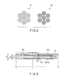
- the regulation wire 103 is provided to face one operation wire 50 as shown in FIG. 2 and FIG. 3C in the diametrical direction of the bending portion 23 (joint ring 30) in order to regulate the bending of the bending portion 23 as described above.
- the regulation wire 103 has a tensile strength and a breaking strength equal to or more than those of the operation wire 50 in order to regulate the bending of the bending portion 23 as described above. Therefore, for example, the diameter of the regulation wire 103 is larger than the diameter of the operation wire 50, as shown in FIG. 3C .
- the regulation wire 103 is made of a material having bending elasticity so that the bending portion 23 can be bent when the bending portion 23 is bent.
- the regulation wire 103 moves back and forth relative to the bending portion 23 along the axial direction of the regulation wire 103 when the bending portion 23 is bent and when the bending portion 23 is restored to a straight state from a bent state.
- a distal end portion 103a of the regulation wire 103 is fixed to the distal rigid portion 21. This fixing is, for example, welding, deposition, or caulking.
- the distal end portion 103a is formed as a fixed end. As shown in FIG.
- a proximal end portion 103b of the regulation wire 103 is provided inside the mouthpiece 26 of the flexible tube portion 25 coupled to the joint ring 31b.
- the proximal end portion 103b is formed as a free end.
- the distal end portion 103a of the regulation wire 103 is fixed as described above, the proximal end portion 103b of the regulation wire 103 moves relative to the bending portion 23 toward the distal rigid portion 21 along the axial direction of the regulation wire 103 when the bending portion 23 is bent.
- the proximal end portion 103b of the regulation wire 103 moves relative to the bending portion 23 toward the mouthpiece 26 of the flexible tube portion 25 along the axial direction.
- the regulation wire 103 is held by a holding member 45a so that the regulation wire 103 is movable (slidable) back and forth relative to the holding member 45a in the axial direction of the regulation wire 103 as shown in FIG. 2 and FIG. 3C when the bending portion 23 is bent and when the bending portion 23 is restored to the straight state from the bent state.
- the holding member 45a is substantially similar in configuration to the holding member 45, and is separate from the holding member 45.
- the holding member 45a is provided in each of the joint rings 30 in the first bending portion 23a and the second bending portion 23b, and the holding member 45a is fixed to the inner circumferential surface 30a of each of the joint rings 30, for example, by welding.
- the holding member 45a is provided out of alignment with the holding member 45 in the circumferential direction of the bending portion 23 (joint ring 30).
- the mouthpiece 26 of the flexible tube portion 25 has, on its edge, a cutout portion 26a into which the holding member 45a is fitted as shown in FIG. 4 to prevent the edge of the mouthpiece 26 from contacting the holding member 45a when fitted into the joint ring 31b.
- the regulation wire 103 is not guided by the wire guide member 101.
- the regulation wire 103 has a prevention portion 105 provided in the proximal end portion 103b of the regulation wire 103.
- the prevention portion 105 contacts the holding member 45a, and thereby regulates the bending of the bending portion 23 as shown in FIG. 6B and prevents the regulation wire 103 from coming off the joint ring 31b.
- This prevention portion 105 has, for example, a cylindrical member to cover the proximal end portion 103b.
- the prevention portion 105 is fitted in, for example, the proximal end portion 103b, and is thicker than the holding member 45a.
- the prevention portion 105 contacts the holding member 45a provided in the joint ring 31b. The prevention portion 105 thereby prevents the regulation wire 103 from coming off the joint ring 31b, and regulates the bending of the bending portion 23 as shown in FIG. 6B .
- the proximal end portion 103b of the regulation wire 103 projects a desired length L from the joint ring 31b toward the mouthpiece 26 of the flexible tube portion 25.
- the desired length L is calculated as below.
- the radius of the joint ring 30 is r.
- the bending radius of the first bending portion 23a is R1 when the bending portion 23 is bent in an S-shape.
- the bending radius of the second bending portion 23b is R2 when the bending portion 23 is bent in an S-shape.
- the bending angle of the first bending portion 23a is ⁇ 1.
- the bending angle of the second bending portion 23b is ⁇ 2.
- the stretch amount r ⁇ 1 of the first bending portion 23a the contraction amount r ⁇ 2 of the second bending portion 23b.
- the bending angle of the whole first bending portion 23a is ⁇ 0
- the bending angle of the first bending portion 23a is ⁇ 0- ⁇ 1 when the first bending portion 23a is bent until the prevention portion 105 contacts the holding member 45a.
- the stretch amount of the first bending portion 23a in this case is r( ⁇ 0- ⁇ 1).
- the above-mentioned desired length L is r( ⁇ 0- ⁇ 1).
- a curvature R1 of the inner circumferential surface is R0-r.
- R1 indicates the curvature of the inner operation wire 50.
- a curvature R2 of the outer circumferential surface is R0+r.
- R2 indicates the curvature of the outer operation wire 50.
- R0 indicates the curvature of the bending portion 23, and P1/2/tan ⁇ 3.
- P1 indicates a length of an axial direction of the joint ring 30.
- ⁇ 3 indicates the bending angle of the joint ring 30.
- a length L0 of an arc of R0 is R0 ⁇ 4.
- a length L1 of an arc of R1 is R1 ⁇ 4.
- a length L2 of an arc of R2 is R2 ⁇ 4.
- ⁇ 0 indicates a bending angle
- the regulation wire 103 is provided to face the downward operation wire 50, and provided adjacent to the upward operation wire 50.
- the downward operation wire 50 for example, is pulled, and the bending portion 23 is bent, for example, downward as shown in FIG. 6A .
- the first bending portion 23a is bent downward before the second bending portion 23b as shown in FIG. 6A because the wire guide member 101 is provided in the second bending portion 23b.
- the second bending portion 23b still remains straight.
- the downward operation wire 50 is disposed on the inner side of the bent bending portion 23, and the upward operation wire 50 (not shown) and the regulation wire 103 are disposed on the outer side of the bent bending portion 23.
- the proximal end portion 103b of the regulation wire 103 moves relative to the bending portion 23 toward the distal rigid portion 21 along the axial direction of the regulation wire 103.
- the path length of the outer circumferential side (the side of the regulation wire 103) of the bending portion 23 is greater than the path length of the inner circumferential side (the side of the downward operation wire 50) of the bending portion 23. Therefore, if the first bending portion 23a is bent as shown in FIG. 6A , the proximal end portion 103b of the regulation wire 103 is retracted toward the distal rigid portion 21. As the regulation wire 103 is made of a material having bending elasticity, the regulation wire 103 bends along the bending shape of the first bending portion 23a while being retracted.
- the regulation wire 103 has a tensile strength and a breaking strength equal to or more than those of the operation wire 50. Therefore, for example, the diameter of the regulation wire 103 is larger than the diameter of the operation wire 50. Thus, the first bending portion 23a is not easily bent because of the regulation wire 103, and a constant path length on the outer circumferential side of the bending portion 23 is maintained. In this way, the bending of the bending portion 23 is regulated by the regulation wire 103.
- the proximal end portion 103b of the regulation wire 103 is retracted toward the distal rigid portion 21 to ensure that the prevention portion 105 contacts the holding member 45a provided in the joint ring 31b. This ensures that a constant path length on the outer circumferential side of the bending portion 23 is maintained. In this way, the bending of the bending portion 23 is regulated by the regulation wire 103.
- the vertical bending operation knob 67b is further operated and the downward operation wire 50, for example, is further pulled, the first bending portion 23a is further bent.
- the regulation wire 103 has a tensile strength and a breaking strength equal to or more than those of the operation wire 50, and the prevention portion 105 is in contact with the holding member 45a, so that a constant path length on the outer circumferential side of the bending portion 23 is maintained. Therefore, more force is applied to the outer circumferential side (the side of the regulation wire 103) of the bending portion 23 than the inner circumferential side (the side of the downward operation wire 50) of the bending portion 23.
- the second bending portion 23b is bent to the side (upper side) opposite to the first bending portion 23a.
- the bending portion 23 is bent in an S-shape, as shown in FIG. 6B .
- the second bending portion 23b is first bent at its distal end (the side of the joint ring 31d) rather than at its proximal end (the side of the joint ring 31b).
- the regulation wire 103 regulates the bending of the bending portion 23 to ensure that the second bending portion 23b is bent in a direction opposite to the bending direction of the first bending portion 23a and that the bending portion 23 is bent in an S-shape because the regulation wire 103 has a tensile strength and a breaking strength equal to or more than those of the operation wire 50 and the prevention portion 105 contacts the holding member 45a.
- the distal rigid portion 21 is moved by the bending of the first bending portion 23a, and moved to be pulled back by the bending of the second bending portion 23b. Consequently, the position of the distal rigid portion 21 is changed, and, for example, the direction of the imaging unit is changed so that the observation target is caught in the imaging field of the imaging unit.
- the first bending portion 23a and the second bending portion 23b are formed in the bending portion 23 by the wire guide member 101.
- the regulation wire 103 is provided to face one operation wire 50 in the diametrical direction of the bending portion 23 (joint ring 30), and has a tensile strength and a breaking strength equal to or more than those of the operation wire 50. Therefore, in the present embodiment, a constant path length on the outer circumferential side of the bending portion 23 can be maintained, the bending of the bending portion 23 is regulated by the regulation wire 103, and the second bending portion 23b can be bent in a direction opposite to the bending direction of the first bending portion 23a.
- the bending portion 23 can be readily bent in an S-shape by one bending operation portion 67.
- the distal end portion 103a of the regulation wire 103 is fixed to the distal rigid portion 21, and the proximal end portion 103b of the regulation wire 103 is movable.
- the regulation wire 103 is longer than the bending portion 23, and the proximal end portion 103b of the regulation wire 103 has the prevention portion 105.
- the prevention portion 105 contacts the holding member 45a when the bending portion 23 is bent.
- this ensures that a constant path length on the outer circumferential side of the bending portion 23 can be maintained, the second bending portion 23b can be bent in a direction opposite to the bending direction of the first bending portion 23a, and the bending portion 23 can be readily bent in an S-shape by one bending operation portion 67.
- the wire guide member 101 is provided in the second bending portion 23b to ensure that the first bending portion 23a can be bent before the second bending portion 23b.
- the regulation wire 103 is made of a material having bending elasticity so that the bending portion 23 can be bent when the bending portion 23 is bent. In the present embodiment, this ensures that the bending portion 23 can be bent.
- FIG. 7A , FIG. 7B , and FIG. 7C a first modification of the embodiment is described with reference to FIG. 7A , FIG. 7B , and FIG. 7C .
- the distal end portion 103a of the regulation wire 103 is fixed to the distal rigid portion 21, the proximal end portion 103b of the regulation wire 103 is movable, and the proximal end portion 103b of the regulation wire 103 has the prevention portion 105.
- the present invention does not need to be limited to this as long as the bending portion 23 can be bent in an S-shape by one bending operation portion 67.
- the proximal end portion 103b of the regulation wire 103 is fixed to the joint ring 31b.
- the distal end portion 103a of the regulation wire 103 is formed as a free end, and is movable along the axial direction of the regulation wire 103.
- the distal end portion 103a of the regulation wire 103 has the prevention portion 105. As shown in FIG. 7B , the prevention portion 105 contacts the holding member 45a provided in the distal rigid portion 21 when the bending portion 23 is bent.
- the distal rigid portion 21 has a groove portion 109 in which the prevention portion 105 can slide along the axial direction of the regulation wire 103.
- the length of this groove portion 109 is the above-mentioned r( ⁇ 0- ⁇ 1).
- the distal end portion 103a and the proximal end portion 103b of the regulation wire 103 may be formed as free ends, and movable along the axial direction of the regulation wire 103.
- the distal end portion 103a and the proximal end portion 103b of the regulation wire 103 may have the prevention portions 105.
- At least one of the distal end portion 103a and the proximal end portion 103b of the regulation wire 103 has only to be formed as a free end so that the regulation wire 103 is movable along the axial direction of the regulation wire 103, and the free end has only to have the prevention portion 105.
- the diameter of the regulation wire 103 is larger than the diameter of the operation wire 50.
- the present invention does not need to be limited to this as long as the regulation wire 103 has a tensile strength and a breaking strength equal to or more than those of the operation wire 50.
- the number of the wires bundled in the regulation wire 103 has only to be larger than the number of the wires bundled in the operation wire 50.
- the regulation wire 103 has only to have a larger amount of a high tensile-and breaking-strength material such as tungsten than the operation wire 50.
- the stretchability of the regulation wire 103 has only to be lower than the stretchability of the operation wire 50.
- the elasticity of the regulation wire 103 has only to be lower than the elasticity of the operation wire 50.
- the operation wire 50 is separate from the regulation wire 103, but may double as the regulation wire 103 as in the present modification.
- the operation wire 50 has, for example, the prevention portion 105 located a predetermined length apart from the holding member 45a of the joint ring 31b toward the mouthpiece 26 of the flexible tube portion 25 when the bending portion 23 is straight.
- the wire guide member 101 is provided up to the side of the holding member 45a of the joint ring 31b, and is not provided in the bending portion 23.
- the inside diameter of the wire guide member 101 is substantially the same as the inside diameter d2 of the prevention portion 105.
- a wire guide member 101a having the same inside diameter d1 as the outside diameter d1 of the wire guide member 101 is provided at the distal end portion of the wire guide member 101.
- the wire guide member 101a is fixed to the distal end portion of the wire guide member 101, for example, by welding.
- the wire guide member 101a is provided up to the holding member 45a of the joint ring 31b from the distal end portion of the wire guide member 101, and is not provided in the bending portion 23.
- the inside diameter d1 of the wire guide member 101a is larger than the outside diameter d2 of the prevention portion 105 and the inside diameter d3 of the holding member 45a.
- the operation wire 50 doubles as the regulation wire 103 while being guided up to the bending portion 23 by the wire guide members 101 and 101a.
- the prevention portion 105 can axially slide the wire guide member 101a together with the regulation wire 103 (operation wire 50).
- the operation wire 50 doubles as the regulation wire 103, so that the number of components can be reduced, and the bending portion 23 can be reduced in diameter.
- the holding member 45 which holds the operation wire 50 and the holding member 45a which holds the regulation wire 103 are separate in the first bending portion 23a.
- the present invention does not need to be limited to this.
- the holding member 45 may integrally hold the operation wire 50 and the regulation wire 103.
- the holding member 45a can be omitted, and the number of processes in the fabrication of the bending portion 23 can be reduced.
- the holding member 45 which holds the operation wire 50 is provided out of alignment in the circumferential direction with the holding member 45a which holds the regulation wire 103 in the first bending portion 23a.
- the present invention does not need to be limited to this.
- the holding member 45 and the holding member 45a may overlap so that the operation wire 50 and the regulation wire 103 do not overlap in the axial direction of the bending portion 23.
- the bending portion 23 can be reduced in diameter.
Landscapes
- Health & Medical Sciences (AREA)
- Life Sciences & Earth Sciences (AREA)
- Surgery (AREA)
- Physics & Mathematics (AREA)
- Optics & Photonics (AREA)
- Biomedical Technology (AREA)
- Animal Behavior & Ethology (AREA)
- Radiology & Medical Imaging (AREA)
- Nuclear Medicine, Radiotherapy & Molecular Imaging (AREA)
- Engineering & Computer Science (AREA)
- Biophysics (AREA)
- Heart & Thoracic Surgery (AREA)
- Medical Informatics (AREA)
- Molecular Biology (AREA)
- Pathology (AREA)
- General Health & Medical Sciences (AREA)
- Public Health (AREA)
- Veterinary Medicine (AREA)
- Rehabilitation Therapy (AREA)
- Astronomy & Astrophysics (AREA)
- General Physics & Mathematics (AREA)
- Instruments For Viewing The Inside Of Hollow Bodies (AREA)
- Endoscopes (AREA)
Abstract
Description
- The present invention relates to an endoscope having a bending portion which can be bent in an S-shape.
- For example,
Patent Literature 1 discloses an endoscope. This endoscope has a first bending portion provided at the distal end of an insertion portion, a second bending portion which is provided at the proximal end of the insertion portion and which is coupled to the first bending portion, and an operation portion which operates the first bending portion. The second bending portion is bent by external force. - For example,
Patent Literature 2 discloses another endoscope. A bending portion of the endoscope is bent preferentially from the distal end portion side of the bending portion. - For example, Patent Literature 3 discloses yet another endoscope. This endoscope has a first bending portion, a second bending portion coupled to the proximal end portion of the first bending portion, a first operation portion which operates the first bending portion, and a second operation portion which operates the second bending portion. Thus, the endoscope has the operation portions which respectively operate the bending portions.
-
- Patent Literature 1: Jpn. Pat. Appln. KOKAI Publication No.
2005-261513 - Patent Literature 2: Jpn. Pat. Appln. KOKAI Publication No.
10-234653 - Patent Literature 3: Jpn. Pat. Appln. KOKAI Publication No.
2004-298466 - For example, in
Patent Literature 1, the second bending portion is only bent by the external force. For example, inPatent Literature 2, the bending portion is bent preferentially from the distal end portion side of the bending portion. When these bending portions need to be bent in an S-shape in, for example, a sigmoid colon in a large intestine, the bending portions are not bent in an S-shape as intended by an operator. This deteriorates the operability of the bending portions. - Moreover, for example, in Patent Literature 3, the first operation portion and the second operation portion are provided. When the operator bends the bending portion in an S-shape, each of the first and second operation portions needs to be operated, thus the operation is complicated.
- The present invention has been made in view of these circumstances, and an object of the invention is to provide an endoscope in which a bending portion can be readily bent in an S-shape by one operation portion.
- An aspect of an endoscope of the present invention includes distal rigid portion comprising an imaging unit configured to image an observation target; a bending portion comprising a first bending portion coupled to the distal rigid portion and a second bending portion coupled to the proximal end portion of the first bending portion; a flexible tube portion coupled to the proximal end portion of the second bending portion; an operation wire which is connected to the distal rigid portion and which is inserted through the first bending portion, the second bending portion, and the flexible tube portion; a wire guide member comprising a distal end fixed to the inside of the distal end of the second bending portion, the wire guide member being inserted through the second bending portion and the flexible tube portion, the wire guide member guiding the operation wire when the operation wire is inserted through the wire guide member; a bending operation portion which is connected to the operation wire and which bends and operates the first bending portion when the bending operation portion pulls the operation wire; and a regulation wire, the regulation wire being longer than the bending portion, the regulation wire being inserted through the first bending portion and the second bending portion, the regulation wire being provided to face the operation wire in the diametrical direction of the bending portion, the regulation wire having a tensile strength and a breaking strength equal to or more than those of the operation wire, and the regulation wire regulating the bending of the bending portion so that the second bending portion is bent in a direction opposite to the bending direction of the first bending portion and the bending portion is bent in an S-shape when the first bending portion is bent.
- According to the present invention, it is able to provide an endoscope in which a bending portion can be readily bent in an S-shape by one operation portion.
-
-
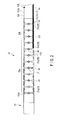
FIG. 1 is a schematic diagram showing an endoscope according to a first embodiment of the present invention; -
FIG. 2 is a diagram simply showing the structure of a bending portion; -
FIG. 3A is a perspective view of a joint ring provided in a first bending portion; -
FIG. 3B is a perspective view of a joint ring provided in a second bending portion; -
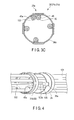
FIG. 3C is a front view of a joint ring through which an operation wire and a regulation wire are inserted; -
FIG. 4 is a perspective view simply showing a coupling structure between a joint ring provided at the proximal end portion of the bending portion and a mouthpiece of a flexible tube portion; -
FIG. 5A is a schematic diagram for calculating a difference L3 between a contracted inner operation wire and a stretched outer operation wire when the bending portion is bent; -
FIG. 5B is a schematic diagram for calculating the difference L3 between the contracted inner operation wire and the stretched outer operation wire when the bending portion is bent; -
FIG. 6A is a schematic diagram in which the first bending portion alone is bent; -
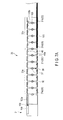
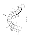
FIG. 6B is a schematic diagram in which the bending portion is bent in an S-shape; -
FIG. 7A is a diagram simply showing the structure of the bending portion according to a first modification; -
FIG. 7B is a schematic diagram in which the first bending portion alone is bent; -
FIG. 7C is a schematic diagram in which the bending portion is bent in an S-shape; -
FIG. 8 is a diagram showing the structures of the operation wire and the regulation wire according to a second modification; -
FIG. 9 is a diagram showing how the operation wire doubles as the regulation wire according to a third modification; -
FIG. 10A is a diagram showing a modification of a holding member according to a fourth modification; and -
FIG. 10B is a diagram showing a modification of the holding member according to a fifth modification. - Hereinafter, embodiments of the present invention will be described in detail with reference to the drawings.
- A first embodiment is described with reference to
FIG. 1 ,FIG. 2 ,FIG. 3A, FIG. 3B ,FIG. 3C, FIG. 4 ,FIG. 5A, FIG. 5B ,FIG. 6A , andFIG. 6B . - As a
wire guide member 101 is not shown in, for example,FIG. 5A , some components are not shown for simplicity in some of the drawings. - In the present embodiment, the longitudinal direction of an
insertion portion 10, the longitudinal direction of a bendingportion 23, and the axial direction of thewire guide member 101 are the same direction. - As shown in
FIG. 1 , anendoscope 1 has theelongate insertion portion 10 to be inserted into, for example, a body cavity of a patient, and anoperation portion 60 which is coupled to the proximal end portion of theinsertion portion 10 and which operates theendoscope 1. - The
insertion portion 10 has a distalrigid portion 21, a bendingportion 23, and aflexible tube portion 25 from the distal end portion side of theinsertion portion 10 to the proximal end portion side of theinsertion portion 10. The proximal end portion of the distalrigid portion 21 is coupled to the distal end portion of the bendingportion 23, and the proximal end portion of the bendingportion 23 is coupled to the distal end portion of theflexible tube portion 25. - The distal
rigid portion 21 functions as the distal end of theendoscope 1 and the distal end of theinsertion portion 10, and is rigid. The distalrigid portion 21 has an unshown imaging unit to image an observation target. - The bending
portion 23 will be described later. - The
flexible tube portion 25 has desired flexibility. Therefore, theflexible tube portion 25 is bent by external force. Theflexible tube portion 25 is a tubular member extending from a later-describedmain body portion 61 in theoperation portion 60. - The
operation portion 60 has themain body portion 61 from which theflexible tube portion 25 extends, a graspingportion 63 which is coupled to the proximal end portion of themain body portion 61 and which is grasped by an operator to operate theendoscope 1, and auniversal cord 65 connected to the graspingportion 63. - The
main body portion 61 has a treatmenttool insertion opening 61a. The treatmenttool insertion opening 61a is coupled to the proximal end portion of an unshown treatment tool insertion channel. The treatment tool insertion channel is provided from theflexible tube portion 25 to the distalrigid portion 21 inside theinsertion portion 10. The treatmenttool insertion opening 61a is an insertion opening to insert an unshown endoscope treatment tool into the treatment tool insertion channel. The unshown endoscope treatment tool is inserted into the treatment tool insertion channel from the treatmenttool insertion opening 61a, and pressed to the side of the distalrigid portion 21. The unshown endoscope treatment tool is then projected from an unshown distal opening portion of the treatment tool insertion channel provided in the distalrigid portion 21. - The grasping
portion 63 has abending operation portion 67 which bends and operates the bendingportion 23. The bendingoperation portion 67 has a horizontal bending operation knob 67a which is operated to horizontally bend the bendingportion 23, and a verticalbending operation knob 67b which is operated to vertically bend the bendingportion 23. The bendingoperation portion 67 further has a fixingknob 67c which fixes the position of thebent bending portion 23. - The horizontal bending operation knob 67a is connected to an unshown horizontal bending operation mechanism driven by the horizontal bending operation knob 67a. The vertical
bending operation knob 67b is connected to an unshown vertical bending operation mechanism driven by the verticalbending operation knob 67b. The vertical bending operation mechanism and the horizontal bending operation mechanism are provided in theoperation portion 60. - The horizontal bending operation mechanism is connected to the proximal end portion of a later-described
operation wire 50 inserted through theflexible tube portion 25 and the bendingportion 23. As shown inFIG. 2 , the distal end portion of thisoperation wire 50 is connected to the distalrigid portion 21, for example, by solder. - The vertical bending operation mechanism is connected to the proximal end portion of an
operation wire 50 inserted through theflexible tube portion 25 and the bendingportion 23. Theoperation wire 50 connected to the vertical bending operation mechanism is different from theoperation wire 50 connected to the horizontal bending operation mechanism. The distal end portion of theoperation wire 50 connected to the vertical bending operation mechanism is connected to the distalrigid portion 21, for example, by solder. - The horizontal bending operation knob 67a horizontally bends the bending
portion 23 via the horizontal bending operation mechanism and theoperation wire 50. The verticalbending operation knob 67b vertically bends the bendingportion 23 via the vertical bending operation mechanism and theoperation wire 50. - The grasping
portion 63 also has aswitch section 69. Theswitch section 69 is operated by the hand of the operator when the graspingportion 63 is grasped by the operator. Theswitch section 69 has asuction switch 69a and an air/water supply switch 69b. Thesuction switch 69a is operated when theendoscope 1 sucks, for example, mucus or fluid from an unshown suction opening provided in the distalrigid portion 21 via an unshown suction channel. The air/water supply switch 69b is operated when fluid is supplied from an unshown air/water supply channel to ensure an imaging field of the unshown imaging unit provided in the distalrigid portion 21. The fluid includes water and gasses. - The grasping
portion 63 also hasvarious buttons 71 for endoscopic photography. - The
universal cord 65 has aconnection portion 65a connected to an unshown video processor or light source device. - Now, the bending
portion 23 is described with reference toFIG. 2 . - The bending
portion 23 is bent in a desired direction, for example, in vertical and horizontal directions by the operation of the bendingoperation portion 67. When the bendingportion 23 is bent, the position and direction of the distalrigid portion 21 are changed, the observation target is caught in the imaging field of the imaging unit, and the observation target is illuminated by illumination light. - As shown in
FIG. 2 , the bendingportion 23 is composed ofjoint rings 30 arrayed along the longitudinal direction of theinsertion portion 10. Thejoint ring 30 has a substantially cylindrical (annular) shape. The adjacent joint rings 30 (front and rear joint rings along the longitudinal direction of the insertion portion 10) are rotatably coupled to each other by a later-describedcoupling portion 39. As the joint rings 30 are rotatably coupled to each other, the bendingportion 23 which can be bent (rotatable) as described above is formed. - The joint rings 30 are described with reference to
FIG. 3A and FIG. 3B . - As described above, the
joint ring 30 has a substantially cylindrical shape. Thejoint ring 30 is made of a rigid material such as a metal. Thejoint ring 30 is molded by, for example, a pressed sheet metal or forging. Suchjoint rings 30 are arrayed along the longitudinal direction of theinsertion portion 10, as shown inFIG. 2 . The adjacent joint rings 30 (front and rear joint rings along the insertion direction of the insertion portion 10) are rotatably coupled to each other by thecoupling portion 39 as described above. - The
joint ring 30 has two projecting pieces (front hinge mounts) 33 provided on the distal end portion side (left side inFIG. 3A and FIG. 3B ) of thejoint ring 30. The projectingpieces 33 are parts of thejoint ring 30 that project forward (to the distal end portion side of the bending portion 23). The projectingpieces 33 are formed into planar shape. Each of the projectingpieces 33 has a through-hole 33a which passes through the projectingpiece 33 in the thickness direction of the projectingpiece 33. Two projectingpieces 33 are located substantially 180° apart from each other in the circumferential direction of thejoint ring 30. - The
joint ring 30 also has two projecting pieces (rear hinge mounts) 35 provided on the rear end portion side (right side inFIG. 3A and FIG. 3B ) of thejoint ring 30. The projectingpieces 35 show parts of thejoint ring 30 that project rearward (to the proximal side of the bending portion 23). The projectingpieces 33 are formed into a planar shape. Each of the projectingpieces 35 has a step which has substantially the same thickness as the thickness of the projectingpiece 33. Each of the projectingpieces 35 also has a through-hole 35a which passes through the projectingpiece 33 in the thickness direction of the projectingpiece 33. Two projectingpieces 35 are located substantially 180° apart from each other in the circumferential direction of thejoint ring 30. - The projecting
piece 33 and the projectingpiece 35 are located substantially 90° apart from each other in the circumferential direction of thejoint ring 30. - In the projecting
piece 35 provided in thejoint ring 30 on the side of the flexible tube portion 25 (the proximal end portion of the insertion portion 20) and in the projectingpiece 33 provided in thejoint ring 30 on the side of the distal rigid portion 21 (the distal end portion of the insertion portion 20), rivets 37 shown inFIG. 2 are inserted into the through-holes rivet 37 functions as a rotation member (pivot shaft) which rotatably couples the joint rings 30. Thus, thejoint ring 30 on the side of theflexible tube portion 25 and thejoint ring 30 on the side of the distalrigid portion 21 are coupled to each other by therivet 37, and pivotally supported rotatably around therivet 37. In this way, therivet 37 is formed as a rotational support shaft provided between the projectingpiece 33 and the projectingpiece 35. - In other words, the projecting
piece 33, the projectingpiece 35, and therivet 37 function as thecoupling portion 39 which couples thejoint ring 30 on the side of theflexible tube portion 25 and thejoint ring 30 on the side of the distalrigid portion 21. - When the joint rings 30 are coupled by the
rivet 37, the projectingpiece 33 provided in thejoint ring 30 on the side of theflexible tube portion 25 is stacked on the projectingpiece 35 provided in thejoint ring 30 on the side of the distalrigid portion 21. - In the bending
portion 23 according to the present embodiment, therivets 37 are alternately located substantially 90° away from each other on the front and rear sides of eachjoint ring 30. Thus, the bendingportion 23 can be bent in four vertical and horizontal directions. - In the present embodiment, the
joint ring 30 provided at the distal end portion of the bendingportion 23 as shown inFIG. 2 andFIG. 3A is a distal end portion joint ring (hereinafter referred to as ajoint ring 31a), and thejoint ring 30 provided at the proximal end portion of the bendingportion 23 as shown inFIG. 2 andFIG. 3B is a proximal end portion joint ring (hereinafter referred to as ajoint ring 31b). As shown inFIG. 2 , thejoint ring 31a is coupled to the distalrigid portion 21. As shown inFIG. 4 , thejoint ring 31b is fitted into amouthpiece 26 of theflexible tube portion 25, and is then coupled to themouthpiece 26 of theflexible tube portion 25, for example, by screws or adhesion. - The
joint ring 30 provided between thejoint ring 31a and thejoint ring 31b as shown inFIG. 2 andFIG. 3A is a distal end portion side joint ring (hereinafter referred to as ajoint ring 31c). Thisjoint ring 31c has a later-described holdingmember 45. Thejoint ring 30 provided between thejoint ring 31c and thejoint ring 31b as shown inFIG. 2 andFIG. 3B is a proximal end portion side joint ring (hereinafter referred to as ajoint ring 31d). The later-describedwire guide member 101 is inserted through thejoint ring 31d. Thejoint ring 31c provided closest to theflexible tube portion 25 and thejoint ring 31d provided closest to the distalrigid portion 21 are rotatably coupled to each other as described above. - As shown in
FIG. 2 , the bendingportion 23 has afirst bending portion 23a coupled to the distalrigid portion 21, and asecond bending portion 23b coupled to the proximal end portion of thefirst bending portion 23a. Thefirst bending portion 23a is formed by the joint rings 30 having thejoint rings 31a and thejoint rings 31c. Thefirst bending portion 23a is operated and bent by the bendingoperation portion 67 when the bendingoperation portion 67 pulls theoperation wire 50. The proximal end portion of thesecond bending portion 23b is coupled to theflexible tube portion 25. Thesecond bending portion 23b is formed by the joint rings 30 having thejoint rings 31d and thejoint rings 31b. Thesecond bending portion 23b is bent by a later-describedregulation wire 103 in a direction opposite to the bending direction of thefirst bending portion 23a as shown inFIG. 6B . In thesecond bending portion 23b, thejoint ring 31d coupled to thejoint ring 31c functions as the distal end portion of thesecond bending portion 23b. Thejoint ring 31b functions as the proximal end portion of thesecond bending portion 23b, and is coupled to themouthpiece 26 of theflexible tube portion 25 as shown inFIG. 4 . - As shown in
FIG. 2 , thesecond bending portion 23b has thewire guide member 101 so that thewire guide member 101 is inserted through thesecond bending portion 23b. The distal end portion of thewire guide member 101 is fixed to the inside of the distal end portion of thesecond bending portion 23b, that is, an innercircumferential surface 30a of thejoint ring 31d coupled to thejoint ring 31c. Although described later, the proximal end portion of thewire guide member 101 is inserted through theflexible tube portion 25. Thewire guide member 101 is provided in thesecond bending portion 23b alone, that is, in thejoint ring 31b and thejoint ring 31d, and is not provided in thefirst bending portion 23a. In other words, the bendingportion 23 in which thewire guide member 101 is provided functions as thesecond bending portion 23b. In the bendingportion 23, thesecond bending portion 23b has thewire guide member 101 provided therein and is therefore more rigid than thefirst bending portion 23a. Thus, the bendingportion 23 is bent from the distal end portion of the bendingportion 23. In other words, thefirst bending portion 23a is bent before thesecond bending portion 23b. - The
wire guide member 101 guides theoperation wire 50 when theoperation wire 50 is inserted through thewire guide member 101. Thewire guide member 101 functions as an elastic tubular member. Thewire guide member 101 is inserted through thesecond bending portion 23b, theflexible tube portion 25, and themain body portion 61. - The
operation wire 50 is inserted through thewire guide member 101 so that theoperation wire 50 is movable back and forth in the axial direction of theoperation wire 50. Thewire guide member 101 functions as a wire insertion member through which theoperation wire 50 is inserted. Thewire guide member 101 protects theoperation wire 50 against inner objects other than theoperation wire 50. The inner objects mean members such as a suction tube provided inside the insertion portion 20. Since thewire guide member 101 is provided in thesecond bending portion 23b as described above, thewire guide member 101 guides and protects theoperation wire 50 in thesecond bending portion 23b. Thewire guide member 101 has, for example, a coil sheath wound around theoperation wire 50. Oneoperation wire 50 is inserted through onewire guide member 101. - In this case, as shown in
FIG. 2 andFIG. 3A , the distal end portion side of theoperation wire 50 projects from thewire guide member 101, and is held by the holdingmembers 45 in thefirst bending portion 23a. As shown inFIG. 2 andFIG. 3A , the holdingmembers 45 are provided in thefirst bending portion 23a, that is, the innercircumferential surfaces 30a of thejoint rings second bending portion 23b, that is, the joint rings 31b and 31d. The holdingmember 45 functions as a receiving member to receive theoperation wire 50. The holdingmember 45 is made of a rigid material such as a metal. As shown inFIG. 3A andFIG. 3C , the holdingmember 45 has, for example, a cylindrical shape. The holdingmembers 45 are fixed to the innercircumferential surface 30a, for example, by welding. The holdingmembers 45 are aligned with the projectingpieces portion 23. Therefore, in thejoint rings members 45 are provided 90° apart in the circumferential direction as shown inFIG. 3C . The holdingmembers 45 provided in thejoint rings portion 23. - The
operation wire 50 is inserted through the holdingmembers 45 so that theoperation wire 50 is movable back and forth in the axial direction of theoperation wire 50 in thefirst bending portion 23a, and theoperation wire 50 is held by the holdingmembers 45. Thus, theoperation wire 50 is guided by thewire guide member 101 in thesecond bending portion 23b, and is held by the holdingmembers 45 in thefirst bending portion 23a. - As described above, the distal end portion of the
operation wire 50 is connected to the distalrigid portion 21. Theoperation wire 50 is inserted through thefirst bending portion 23a, thesecond bending portion 23b, theflexible tube portion 25, and themain body portion 61. The proximal end portion of theoperation wire 50 is connected to the bending operation mechanism. - As shown in
FIG. 2 , theregulation wire 103 is inserted through the bending portion 23 (thefirst bending portion 23a and thesecond bending portion 23b). Theregulation wire 103 regulates the bending of the bendingportion 23 so that thesecond bending portion 23b is bent in a direction opposite to the bending direction of thefirst bending portion 23a as shown inFIG. 6B and the bendingportion 23 is bent in an S-shape when thefirst bending portion 23a is bent as shown inFIG. 6A . Theregulation wire 103 is separate from theoperation wire 50. As shown inFIG. 2 , theregulation wire 103 is longer than the bendingportion 23. - For example, one
regulation wire 103 is provided. Theregulation wire 103 is provided to face oneoperation wire 50 as shown inFIG. 2 andFIG. 3C in the diametrical direction of the bending portion 23 (joint ring 30) in order to regulate the bending of the bendingportion 23 as described above. Theregulation wire 103 has a tensile strength and a breaking strength equal to or more than those of theoperation wire 50 in order to regulate the bending of the bendingportion 23 as described above. Therefore, for example, the diameter of theregulation wire 103 is larger than the diameter of theoperation wire 50, as shown inFIG. 3C . Theregulation wire 103 is made of a material having bending elasticity so that the bendingportion 23 can be bent when the bendingportion 23 is bent. - As shown in
FIG. 2 ,FIG. 6A , andFIG. 6B , theregulation wire 103 moves back and forth relative to the bendingportion 23 along the axial direction of theregulation wire 103 when the bendingportion 23 is bent and when the bendingportion 23 is restored to a straight state from a bent state. In the present embodiment, as shown inFIG. 2 , for example, adistal end portion 103a of theregulation wire 103 is fixed to the distalrigid portion 21. This fixing is, for example, welding, deposition, or caulking. Thedistal end portion 103a is formed as a fixed end. As shown inFIG. 2 , when the bendingportion 23 has a natural length and is stretched straight, aproximal end portion 103b of theregulation wire 103 is provided inside themouthpiece 26 of theflexible tube portion 25 coupled to thejoint ring 31b. Theproximal end portion 103b is formed as a free end. As thedistal end portion 103a of theregulation wire 103 is fixed as described above, theproximal end portion 103b of theregulation wire 103 moves relative to the bendingportion 23 toward the distalrigid portion 21 along the axial direction of theregulation wire 103 when the bendingportion 23 is bent. When the bendingportion 23 is restored to the straight state from the bent state, theproximal end portion 103b of theregulation wire 103 moves relative to the bendingportion 23 toward themouthpiece 26 of theflexible tube portion 25 along the axial direction. - The
regulation wire 103 is held by a holdingmember 45a so that theregulation wire 103 is movable (slidable) back and forth relative to the holdingmember 45a in the axial direction of theregulation wire 103 as shown inFIG. 2 andFIG. 3C when the bendingportion 23 is bent and when the bendingportion 23 is restored to the straight state from the bent state. The holdingmember 45a is substantially similar in configuration to the holdingmember 45, and is separate from the holdingmember 45. The holdingmember 45a is provided in each of the joint rings 30 in thefirst bending portion 23a and thesecond bending portion 23b, and the holdingmember 45a is fixed to the innercircumferential surface 30a of each of the joint rings 30, for example, by welding. As shown inFIG. 3C , the holdingmember 45a is provided out of alignment with the holdingmember 45 in the circumferential direction of the bending portion 23 (joint ring 30). - The
mouthpiece 26 of theflexible tube portion 25 has, on its edge, acutout portion 26a into which the holdingmember 45a is fitted as shown inFIG. 4 to prevent the edge of themouthpiece 26 from contacting the holdingmember 45a when fitted into thejoint ring 31b. - As shown in
FIG. 2 , theregulation wire 103 is not guided by thewire guide member 101. - As shown in
FIG. 2 andFIG. 4 , theregulation wire 103 has aprevention portion 105 provided in theproximal end portion 103b of theregulation wire 103. When the bendingportion 23 is bent as shown inFIG. 6A so that theregulation wire 103 moves toward the distalrigid portion 21, theprevention portion 105 contacts the holdingmember 45a, and thereby regulates the bending of the bendingportion 23 as shown inFIG. 6B and prevents theregulation wire 103 from coming off thejoint ring 31b. Thisprevention portion 105 has, for example, a cylindrical member to cover theproximal end portion 103b. Theprevention portion 105 is fitted in, for example, theproximal end portion 103b, and is thicker than the holdingmember 45a. When the bendingportion 23 is bent as shown inFIG. 6A so that theproximal end portion 103b of theregulation wire 103 moves toward the distalrigid portion 21, theprevention portion 105 contacts the holdingmember 45a provided in thejoint ring 31b. Theprevention portion 105 thereby prevents theregulation wire 103 from coming off thejoint ring 31b, and regulates the bending of the bendingportion 23 as shown inFIG. 6B . - As shown in
FIG. 2 , when the bendingportion 23 is straight, theproximal end portion 103b of theregulation wire 103 projects a desired length L from thejoint ring 31b toward themouthpiece 26 of theflexible tube portion 25. The desired length L is calculated as below. - As shown in
FIG. 6B , for example, the radius of thejoint ring 30 is r. - As shown in
FIG. 6B , the bending radius of thefirst bending portion 23a is R1 when the bendingportion 23 is bent in an S-shape. - As shown in
FIG. 6B , the bending radius of thesecond bending portion 23b is R2 when the bendingportion 23 is bent in an S-shape. - When the bending
portion 23 is bent in an S-shape and thefirst bending portion 23a is further bent after theprevention portion 105 has contacted the holdingmember 45a, the bending angle of thefirst bending portion 23a is θ1. - When the bending
portion 23 is bent in an S-shape and thesecond bending portion 23b is bent after theprevention portion 105 has contacted the holdingmember 45a, the bending angle of thesecond bending portion 23b is θ2. - In this case, the stretch amount rθ1 of the
first bending portion 23a = the contraction amount rθ2 of thesecond bending portion 23b. - When R1=R2, θ1=θ2.
- If the bending angle of the whole
first bending portion 23a is θ0, the bending angle of thefirst bending portion 23a is θ0-θ1 when thefirst bending portion 23a is bent until theprevention portion 105 contacts the holdingmember 45a. - The stretch amount of the
first bending portion 23a in this case is r(θ0-θ1). - The above-mentioned desired length L is r(θ0-θ1).
- When the
first bending portion 23a and thesecond bending portion 23b are bent in the same direction as shown inFIG. 5A , a difference L3 between the contractedinner operation wire 50 and the stretchedouter operation wire 50 is calculated as below. - A curvature R1 of the inner circumferential surface is R0-r. R1 indicates the curvature of the
inner operation wire 50. - A curvature R2 of the outer circumferential surface is R0+r. R2 indicates the curvature of the
outer operation wire 50. - R0 indicates the curvature of the bending
portion 23, and P1/2/tanθ3. - As shown in
FIG. 5B , P1 indicates a length of an axial direction of thejoint ring 30. θ3 indicates the bending angle of thejoint ring 30. - A length L0 of an arc of R0 is R0θ4.
- A length L1 of an arc of R1 is R1θ4.
- A length L2 of an arc of R2 is R2θ4.
- θ0 indicates a bending angle.
- In this case, the difference L3 between the contracted
inner operation wire 50 and the stretchedouter operation wire 50 is L2-L1=(R2-R1)θ4=2rθ4. - Now, an operation method according to the present embodiment is described.
- Here, the
regulation wire 103 is provided to face thedownward operation wire 50, and provided adjacent to theupward operation wire 50. - For example, if the vertical
bending operation knob 67b is operated, thedownward operation wire 50, for example, is pulled, and the bendingportion 23 is bent, for example, downward as shown inFIG. 6A . At the same time, thefirst bending portion 23a is bent downward before thesecond bending portion 23b as shown inFIG. 6A because thewire guide member 101 is provided in thesecond bending portion 23b. Thesecond bending portion 23b still remains straight. - Moreover, at the same time, the
downward operation wire 50 is disposed on the inner side of thebent bending portion 23, and the upward operation wire 50 (not shown) and theregulation wire 103 are disposed on the outer side of thebent bending portion 23. As a result, theproximal end portion 103b of theregulation wire 103 moves relative to the bendingportion 23 toward the distalrigid portion 21 along the axial direction of theregulation wire 103. - More specifically, the path length of the outer circumferential side (the side of the regulation wire 103) of the bending
portion 23 is greater than the path length of the inner circumferential side (the side of the downward operation wire 50) of the bendingportion 23. Therefore, if thefirst bending portion 23a is bent as shown inFIG. 6A , theproximal end portion 103b of theregulation wire 103 is retracted toward the distalrigid portion 21. As theregulation wire 103 is made of a material having bending elasticity, theregulation wire 103 bends along the bending shape of thefirst bending portion 23a while being retracted. - The
regulation wire 103 has a tensile strength and a breaking strength equal to or more than those of theoperation wire 50. Therefore, for example, the diameter of theregulation wire 103 is larger than the diameter of theoperation wire 50. Thus, thefirst bending portion 23a is not easily bent because of theregulation wire 103, and a constant path length on the outer circumferential side of the bendingportion 23 is maintained. In this way, the bending of the bendingportion 23 is regulated by theregulation wire 103. - The
proximal end portion 103b of theregulation wire 103 is retracted toward the distalrigid portion 21 to ensure that theprevention portion 105 contacts the holdingmember 45a provided in thejoint ring 31b. This ensures that a constant path length on the outer circumferential side of the bendingportion 23 is maintained. In this way, the bending of the bendingportion 23 is regulated by theregulation wire 103. - In this condition, if the vertical
bending operation knob 67b is further operated and thedownward operation wire 50, for example, is further pulled, thefirst bending portion 23a is further bent. However, theregulation wire 103 has a tensile strength and a breaking strength equal to or more than those of theoperation wire 50, and theprevention portion 105 is in contact with the holdingmember 45a, so that a constant path length on the outer circumferential side of the bendingportion 23 is maintained. Therefore, more force is applied to the outer circumferential side (the side of the regulation wire 103) of the bendingportion 23 than the inner circumferential side (the side of the downward operation wire 50) of the bendingportion 23. Thus, force is applied to thesecond bending portion 23b in a direction (upward direction) opposite to thefirst bending portion 23a, and thesecond bending portion 23b is bent to the side (upper side) opposite to thefirst bending portion 23a. As a result, the bendingportion 23 is bent in an S-shape, as shown inFIG. 6B . In this case, thesecond bending portion 23b is first bent at its distal end (the side of thejoint ring 31d) rather than at its proximal end (the side of thejoint ring 31b). - Thus, when the
first bending portion 23a is bent, theregulation wire 103 regulates the bending of the bendingportion 23 to ensure that thesecond bending portion 23b is bent in a direction opposite to the bending direction of thefirst bending portion 23a and that the bendingportion 23 is bent in an S-shape because theregulation wire 103 has a tensile strength and a breaking strength equal to or more than those of theoperation wire 50 and theprevention portion 105 contacts the holdingmember 45a. - Then the distal
rigid portion 21 is moved by the bending of thefirst bending portion 23a, and moved to be pulled back by the bending of thesecond bending portion 23b. Consequently, the position of the distalrigid portion 21 is changed, and, for example, the direction of the imaging unit is changed so that the observation target is caught in the imaging field of the imaging unit. - As described above, in the present embodiment, the
first bending portion 23a and thesecond bending portion 23b are formed in the bendingportion 23 by thewire guide member 101. Moreover, in the present embodiment, theregulation wire 103 is provided to face oneoperation wire 50 in the diametrical direction of the bending portion 23 (joint ring 30), and has a tensile strength and a breaking strength equal to or more than those of theoperation wire 50. Therefore, in the present embodiment, a constant path length on the outer circumferential side of the bendingportion 23 can be maintained, the bending of the bendingportion 23 is regulated by theregulation wire 103, and thesecond bending portion 23b can be bent in a direction opposite to the bending direction of thefirst bending portion 23a. - Consequently, in the present embodiment, the bending
portion 23 can be readily bent in an S-shape by onebending operation portion 67. - In the present embodiment, the
distal end portion 103a of theregulation wire 103 is fixed to the distalrigid portion 21, and theproximal end portion 103b of theregulation wire 103 is movable. In the present embodiment, theregulation wire 103 is longer than the bendingportion 23, and theproximal end portion 103b of theregulation wire 103 has theprevention portion 105. In the present embodiment, theprevention portion 105 contacts the holdingmember 45a when the bendingportion 23 is bent. In the present embodiment, this ensures that a constant path length on the outer circumferential side of the bendingportion 23 can be maintained, thesecond bending portion 23b can be bent in a direction opposite to the bending direction of thefirst bending portion 23a, and the bendingportion 23 can be readily bent in an S-shape by onebending operation portion 67. - In the present embodiment, the
wire guide member 101 is provided in thesecond bending portion 23b to ensure that thefirst bending portion 23a can be bent before thesecond bending portion 23b. - In the present embodiment, the
regulation wire 103 is made of a material having bending elasticity so that the bendingportion 23 can be bent when the bendingportion 23 is bent. In the present embodiment, this ensures that the bendingportion 23 can be bent. - Now, a first modification of the embodiment is described with reference to
FIG. 7A ,FIG. 7B , andFIG. 7C . - In the embodiment, the
distal end portion 103a of theregulation wire 103 is fixed to the distalrigid portion 21, theproximal end portion 103b of theregulation wire 103 is movable, and theproximal end portion 103b of theregulation wire 103 has theprevention portion 105. However, the present invention does not need to be limited to this as long as the bendingportion 23 can be bent in an S-shape by onebending operation portion 67. - For example, the
proximal end portion 103b of theregulation wire 103 is fixed to thejoint ring 31b. Thedistal end portion 103a of theregulation wire 103 is formed as a free end, and is movable along the axial direction of theregulation wire 103. Thedistal end portion 103a of theregulation wire 103 has theprevention portion 105. As shown inFIG. 7B , theprevention portion 105 contacts the holdingmember 45a provided in the distalrigid portion 21 when the bendingportion 23 is bent. - In this case, the distal
rigid portion 21 has agroove portion 109 in which theprevention portion 105 can slide along the axial direction of theregulation wire 103. The length of thisgroove portion 109 is the above-mentioned r(θ0-θ1). - Alternatively, for example, the
distal end portion 103a and theproximal end portion 103b of theregulation wire 103 may be formed as free ends, and movable along the axial direction of theregulation wire 103. In this case, thedistal end portion 103a and theproximal end portion 103b of theregulation wire 103 may have theprevention portions 105. - Thus, in the present modification, at least one of the
distal end portion 103a and theproximal end portion 103b of theregulation wire 103 has only to be formed as a free end so that theregulation wire 103 is movable along the axial direction of theregulation wire 103, and the free end has only to have theprevention portion 105. - Now, a second modification of the embodiment is described with reference to
FIG. 8 . - In the embodiment, the diameter of the
regulation wire 103 is larger than the diameter of theoperation wire 50. However, the present invention does not need to be limited to this as long as theregulation wire 103 has a tensile strength and a breaking strength equal to or more than those of theoperation wire 50. - As shown in
FIG. 8 , for example, when theoperation wire 50 and theregulation wire 103 are formed by bundles of wires, the number of the wires bundled in theregulation wire 103 has only to be larger than the number of the wires bundled in theoperation wire 50. - Alternatively, for example, the
regulation wire 103 has only to have a larger amount of a high tensile-and breaking-strength material such as tungsten than theoperation wire 50. - Alternatively, the stretchability of the
regulation wire 103 has only to be lower than the stretchability of theoperation wire 50. Alternatively, the elasticity of theregulation wire 103 has only to be lower than the elasticity of theoperation wire 50. - Now, a third modification of the embodiment is described with reference to
FIG. 9 . - In the embodiment, the
operation wire 50 is separate from theregulation wire 103, but may double as theregulation wire 103 as in the present modification. In this case, theoperation wire 50 has, for example, theprevention portion 105 located a predetermined length apart from the holdingmember 45a of thejoint ring 31b toward themouthpiece 26 of theflexible tube portion 25 when the bendingportion 23 is straight. Thewire guide member 101 is provided up to the side of the holdingmember 45a of thejoint ring 31b, and is not provided in the bendingportion 23. The inside diameter of thewire guide member 101 is substantially the same as the inside diameter d2 of theprevention portion 105. Therefore, awire guide member 101a having the same inside diameter d1 as the outside diameter d1 of thewire guide member 101 is provided at the distal end portion of thewire guide member 101. Thewire guide member 101a is fixed to the distal end portion of thewire guide member 101, for example, by welding. Thewire guide member 101a is provided up to the holdingmember 45a of thejoint ring 31b from the distal end portion of thewire guide member 101, and is not provided in the bendingportion 23. The inside diameter d1 of thewire guide member 101a is larger than the outside diameter d2 of theprevention portion 105 and the inside diameter d3 of the holdingmember 45a. - Thus, the
operation wire 50 doubles as theregulation wire 103 while being guided up to the bendingportion 23 by thewire guide members prevention portion 105 can axially slide thewire guide member 101a together with the regulation wire 103 (operation wire 50). - Thus, in the present modification, the
operation wire 50 doubles as theregulation wire 103, so that the number of components can be reduced, and the bendingportion 23 can be reduced in diameter. - Now, a fourth modification of the embodiment is described with reference to
FIG. 10A . - In the embodiment, the holding
member 45 which holds theoperation wire 50 and the holdingmember 45a which holds theregulation wire 103 are separate in thefirst bending portion 23a. However, the present invention does not need to be limited to this. - For example, as in the present modification, the holding
member 45 may integrally hold theoperation wire 50 and theregulation wire 103. Thus, in the present modification, the holdingmember 45a can be omitted, and the number of processes in the fabrication of the bendingportion 23 can be reduced. - Now, a fifth modification of the embodiment is described with reference to
FIG. 10B . - In the embodiment, the holding
member 45 which holds theoperation wire 50 is provided out of alignment in the circumferential direction with the holdingmember 45a which holds theregulation wire 103 in thefirst bending portion 23a. However, the present invention does not need to be limited to this. - For example, as in the present modification, the holding
member 45 and the holdingmember 45a may overlap so that theoperation wire 50 and theregulation wire 103 do not overlap in the axial direction of the bendingportion 23. Thus, in the present modification, the bendingportion 23 can be reduced in diameter. - The present invention is not completely limited to the embodiment described above, and modifications of components can be made at the stage of carrying out the invention without departing from the spirit thereof. Various inventions can be made by a proper combination of the components disclosed in the embodiment described above.
Claims (7)
- An endoscope comprising:a distal rigid portion comprising an imaging unit configured to image an observation target;a bending portion comprising a first bending portion coupled to the distal rigid portion and a second bending portion coupled to the proximal end portion of the first bending portion;a flexible tube portion coupled to the proximal end portion of the second bending portion;an operation wire which is connected to the distal rigid portion and which is inserted through the first bending portion, the second bending portion, and the flexible tube portion;a wire guide member comprising a distal end fixed to the inside of the distal end of the second bending portion, the wire guide member being inserted through the second bending portion and the flexible tube portion, the wire guide member guiding the operation wire when the operation wire is inserted through the wire guide member;a bending operation portion which is connected to the operation wire and which bends and operates the first bending portion when the bending operation portion pulls the operation wire; anda regulation wire, the regulation wire being longer than the bending portion, the regulation wire being inserted through the first bending portion and the second bending portion, the regulation wire being provided to face the operation wire in the diametrical direction of the bending portion, the regulation wire having a tensile strength and a breaking strength equal to or more than those of the operation wire, and the regulation wire regulating the bending of the bending portion so that the second bending portion is bent in a direction opposite to the bending direction of the first bending portion and the bending portion is bent in an S-shape when the first bending portion is bent.
- The endoscope according to claim 1, wherein
the first bending portion and the second bending portion comprise holding members which hold the regulation wire,
at least one of the distal end portion and the proximal end portion of the regulation wire is formed as a free end so that the regulation wire is movable along the axial direction of the regulation wire, and
the free end comprises a prevention portion which contacts the holding member, and thereby regulates the bending of the bending portion and prevents the regulation wire from coming off the bending portion. - The endoscope according to claim 1 or claim 2, wherein
the diameter of the regulation wire is larger than the diameter of the operation wire. - The endoscope according to one of claim 1 to 3, wherein
when the operation wire and the regulation wire are formed by bundles of wires, the number of the wires bundled in the regulation wire is larger than the number of the wires bundled in the operation wire. - The endoscope according to one of claim 1 to 4, wherein
the stretchability of the regulation wire is lower than the stretchability of the operation wire. - The endoscope according to one of claim 1 to 5, wherein
the elasticity of the regulation wire is lower than the elasticity of the operation wire. - The endoscope according to one of claim 1 to 6, wherein
more than one operation wire is provided to face each other in the diametrical direction of the bending portion, and
one of the operation wires doubles as the regulation wire.
Applications Claiming Priority (2)
| Application Number | Priority Date | Filing Date | Title |
|---|---|---|---|
| JP2012179845 | 2012-08-14 | ||
| PCT/JP2013/063824 WO2014027487A1 (en) | 2012-08-14 | 2013-05-17 | Endoscope |
Publications (2)
| Publication Number | Publication Date |
|---|---|
| EP2886036A1 true EP2886036A1 (en) | 2015-06-24 |
| EP2886036A4 EP2886036A4 (en) | 2016-04-13 |
Family
ID=50685520
Family Applications (1)
| Application Number | Title | Priority Date | Filing Date |
|---|---|---|---|
| EP13879618.0A Withdrawn EP2886036A4 (en) | 2012-08-14 | 2013-05-17 | Borescope |
Country Status (5)
| Country | Link |
|---|---|
| US (1) | US8905919B2 (en) |
| EP (1) | EP2886036A4 (en) |
| JP (1) | JP5425354B1 (en) |
| CN (1) | CN103764010B (en) |
| WO (1) | WO2014027487A1 (en) |
Families Citing this family (15)
| Publication number | Priority date | Publication date | Assignee | Title |
|---|---|---|---|---|
| AU2011283048B2 (en) | 2010-07-28 | 2016-02-11 | Medrobotics Corporation | Surgical positioning and support system |
| CA2815396A1 (en) * | 2010-10-22 | 2012-04-26 | Medrobotics Corporation | Highly articulated robotic probes and methods of production and use of such probes |
| JP6167041B2 (en) | 2010-11-11 | 2017-07-19 | メドロボティクス コーポレイション | Introduction assembly for articulated robotic probes |
| US9757856B2 (en) | 2011-09-13 | 2017-09-12 | Medrobotics Corporation | Highly articulated probes with anti-twist link arrangement, methods of formation thereof, and methods of performing medical procedures |
| US9855404B2 (en) * | 2013-05-03 | 2018-01-02 | St. Jude Medical International Holding S.À R.L. | Dual bend radii steering catheter |
| JP5885887B2 (en) * | 2014-01-29 | 2016-03-16 | オリンパス株式会社 | Rigid endoscope and treatment tool for prostate biopsy |
| WO2015159619A1 (en) * | 2014-04-15 | 2015-10-22 | オリンパス株式会社 | Bending endoscope tube, endoscope, and method for manufacturing bending endoscope tube |
| CN105759418B (en) * | 2014-12-19 | 2019-06-28 | 深圳市锐丽视科技有限公司 | Flexible number endoscope |
| US10636555B2 (en) * | 2016-08-22 | 2020-04-28 | Seyed Mostafa Zareei | Articulated video probe with magnetic stimulation |
| CN110352043B (en) | 2017-01-19 | 2024-09-20 | 俄亥俄州国家创新基金会 | System and method for mechanical displacement of esophagus |
| CN111200962A (en) * | 2017-10-11 | 2020-05-26 | 奥林巴斯株式会社 | Operation wire pulling device for endoscope |
| WO2020031378A1 (en) * | 2018-08-10 | 2020-02-13 | オリンパス株式会社 | Endoscope |
| CN110859586A (en) * | 2019-11-26 | 2020-03-06 | 上海熠达光电科技有限公司 | Endoscope bending part |
| CN117628045A (en) * | 2022-08-19 | 2024-03-01 | 武汉联影智融医疗科技有限公司 | A kind of curved structure and medical device |
| CN116077004B (en) * | 2022-12-05 | 2026-02-17 | 浙江优亿医疗器械股份有限公司 | Endoscope and bending structure thereof |
Family Cites Families (18)
| Publication number | Priority date | Publication date | Assignee | Title |
|---|---|---|---|---|
| US3799151A (en) * | 1970-12-21 | 1974-03-26 | Olympus Optical Co | Controllably bendable tube of an endoscope |
| JP2987452B2 (en) * | 1990-05-17 | 1999-12-06 | オリンパス光学工業株式会社 | Endoscope |
| DE4305376C1 (en) * | 1993-02-22 | 1994-09-29 | Wolf Gmbh Richard | Medical instrument shaft |
| JP3752328B2 (en) * | 1996-11-06 | 2006-03-08 | オリンパス株式会社 | Endoscope device |
| JPH10234653A (en) | 1997-02-28 | 1998-09-08 | Olympus Optical Co Ltd | Endoscope |
| DE10100533A1 (en) * | 2001-01-09 | 2002-07-18 | Xion Gmbh | Endoscope device especially for emergency medical intubations has improved positioning and control elements that are also more economical and easier to repair than existing devices |
| JP4409844B2 (en) * | 2003-03-31 | 2010-02-03 | 富士フイルム株式会社 | Endoscope |
| JP2004298466A (en) | 2003-03-31 | 2004-10-28 | Roooringu:Kk | Cushion with loops and cushion cover |
| JP4598410B2 (en) * | 2003-05-27 | 2010-12-15 | オリンパス株式会社 | Endoscope |
| JP2005040293A (en) * | 2003-07-28 | 2005-02-17 | Olympus Corp | Endoscope |
| JP2005261513A (en) | 2004-03-17 | 2005-09-29 | Pentax Corp | Flexible endoscope insertion part |
| JP2006068393A (en) * | 2004-09-03 | 2006-03-16 | Olympus Corp | Endoscope |
| JP4477519B2 (en) * | 2005-02-14 | 2010-06-09 | オリンパス株式会社 | Endoscope |
| JP2009160211A (en) * | 2008-01-07 | 2009-07-23 | Fujifilm Corp | Endoscope bending operation device and endoscope |
| US20090287054A1 (en) | 2008-05-19 | 2009-11-19 | Olympus Medical Systems Corp. | Bending tube and medical apparatus |
| WO2011040104A1 (en) * | 2009-09-30 | 2011-04-07 | オリンパスメディカルシステムズ株式会社 | Endoscope device and method for controlling driving of curving |
| JPWO2011092899A1 (en) * | 2010-01-28 | 2013-05-30 | オリンパスメディカルシステムズ株式会社 | Duodenoscope with front view of nipple |
| WO2011114570A1 (en) * | 2010-03-15 | 2011-09-22 | オリンパスメディカルシステムズ株式会社 | Endoscope |
-
2013
- 2013-05-17 CN CN201380002786.4A patent/CN103764010B/en active Active
- 2013-05-17 EP EP13879618.0A patent/EP2886036A4/en not_active Withdrawn
- 2013-05-17 JP JP2013544050A patent/JP5425354B1/en active Active
- 2013-05-17 WO PCT/JP2013/063824 patent/WO2014027487A1/en not_active Ceased
- 2013-10-15 US US14/054,352 patent/US8905919B2/en active Active
Also Published As
| Publication number | Publication date |
|---|---|
| JPWO2014027487A1 (en) | 2016-07-25 |
| CN103764010A (en) | 2014-04-30 |
| WO2014027487A1 (en) | 2014-02-20 |
| JP5425354B1 (en) | 2014-02-26 |
| US8905919B2 (en) | 2014-12-09 |
| CN103764010B (en) | 2015-12-30 |
| EP2886036A4 (en) | 2016-04-13 |
| US20140088356A1 (en) | 2014-03-27 |
Similar Documents
| Publication | Publication Date | Title |
|---|---|---|
| EP2886036A1 (en) | Endoscope | |
| EP1867270B1 (en) | Flexible tube for endoscope and endoscope device | |
| EP2628434B1 (en) | Endoscope | |
| US9172227B2 (en) | Wire guide member | |
| EP2446802B1 (en) | Insertion instrument, endoscope | |
| US20100168519A1 (en) | Endoscope Flexible Tube and Endoscope Device | |
| US8591404B2 (en) | Bending device for endoscope | |
| US9173552B2 (en) | Endoscope | |
| EP2664267A1 (en) | Flexible tube part for endoscope and endoscope having flexible tube part | |
| JP5606812B2 (en) | Endoscope guide tube | |
| EP2679138A1 (en) | Endsoscope | |
| EP1870017B1 (en) | Endoscope insertion portion | |
| JP6230227B2 (en) | Insertion device and endoscope | |
| JP6689589B2 (en) | Endoscope | |
| CN112312820B (en) | Endoscope | |
| JP2007054400A (en) | Endoscope | |
| JP4777005B2 (en) | Endoscope | |
| JP3869081B2 (en) | Endoscope | |
| JP3927194B2 (en) | Endoscope | |
| JP2004195256A (en) | Endoscope | |
| JPH11197101A (en) | Endoscope |
Legal Events
| Date | Code | Title | Description |
|---|---|---|---|
| PUAI | Public reference made under article 153(3) epc to a published international application that has entered the european phase |
Free format text: ORIGINAL CODE: 0009012 |
|
| 17P | Request for examination filed |
Effective date: 20150304 |
|
| AK | Designated contracting states |
Kind code of ref document: A1 Designated state(s): AL AT BE BG CH CY CZ DE DK EE ES FI FR GB GR HR HU IE IS IT LI LT LU LV MC MK MT NL NO PL PT RO RS SE SI SK SM TR |
|
| AX | Request for extension of the european patent |
Extension state: BA ME |
|
| RAP1 | Party data changed (applicant data changed or rights of an application transferred) |
Owner name: OLYMPUS CORPORATION |
|
| DAX | Request for extension of the european patent (deleted) | ||
| RA4 | Supplementary search report drawn up and despatched (corrected) |
Effective date: 20160315 |
|
| RIC1 | Information provided on ipc code assigned before grant |
Ipc: G02B 23/24 20060101ALI20160309BHEP Ipc: A61B 1/00 20060101AFI20160309BHEP |
|
| RAP1 | Party data changed (applicant data changed or rights of an application transferred) |
Owner name: OLYMPUS CORPORATION |
|
| RAP1 | Party data changed (applicant data changed or rights of an application transferred) |
Owner name: OLYMPUS CORPORATION |
|
| RIN1 | Information on inventor provided before grant (corrected) |
Inventor name: MATSUO, SHIGEKI Inventor name: OKANIWA, SUGURU |
|
| GRAP | Despatch of communication of intention to grant a patent |
Free format text: ORIGINAL CODE: EPIDOSNIGR1 |
|
| STAA | Information on the status of an ep patent application or granted ep patent |
Free format text: STATUS: GRANT OF PATENT IS INTENDED |
|
| INTG | Intention to grant announced |
Effective date: 20171205 |
|
| RIN1 | Information on inventor provided before grant (corrected) |
Inventor name: OKANIWA, SUGURU Inventor name: MATSUO, SHIGEKI |
|
| STAA | Information on the status of an ep patent application or granted ep patent |
Free format text: STATUS: THE APPLICATION IS DEEMED TO BE WITHDRAWN |
|
| 18D | Application deemed to be withdrawn |
Effective date: 20180417 |