EP2884814B1 - Radio communications - Google Patents
Radio communications Download PDFInfo
- Publication number
- EP2884814B1 EP2884814B1 EP13199432.9A EP13199432A EP2884814B1 EP 2884814 B1 EP2884814 B1 EP 2884814B1 EP 13199432 A EP13199432 A EP 13199432A EP 2884814 B1 EP2884814 B1 EP 2884814B1
- Authority
- EP
- European Patent Office
- Prior art keywords
- message
- signal strength
- data value
- received signal
- threshold
- Prior art date
- Legal status (The legal status is an assumption and is not a legal conclusion. Google has not performed a legal analysis and makes no representation as to the accuracy of the status listed.)
- Active
Links
Images



Classifications
-
- H—ELECTRICITY
- H04—ELECTRIC COMMUNICATION TECHNIQUE
- H04W—WIRELESS COMMUNICATION NETWORKS
- H04W8/00—Network data management
- H04W8/005—Discovery of network devices, e.g. terminals
-
- H—ELECTRICITY
- H04—ELECTRIC COMMUNICATION TECHNIQUE
- H04W—WIRELESS COMMUNICATION NETWORKS
- H04W76/00—Connection management
- H04W76/10—Connection setup
-
- H—ELECTRICITY
- H04—ELECTRIC COMMUNICATION TECHNIQUE
- H04W—WIRELESS COMMUNICATION NETWORKS
- H04W24/00—Supervisory, monitoring or testing arrangements
- H04W24/02—Arrangements for optimising operational condition
-
- H—ELECTRICITY
- H04—ELECTRIC COMMUNICATION TECHNIQUE
- H04W—WIRELESS COMMUNICATION NETWORKS
- H04W4/00—Services specially adapted for wireless communication networks; Facilities therefor
- H04W4/80—Services using short range communication, e.g. near-field communication [NFC], radio-frequency identification [RFID] or low energy communication
-
- H—ELECTRICITY
- H04—ELECTRIC COMMUNICATION TECHNIQUE
- H04W—WIRELESS COMMUNICATION NETWORKS
- H04W76/00—Connection management
- H04W76/10—Connection setup
- H04W76/14—Direct-mode setup
-
- H—ELECTRICITY
- H04—ELECTRIC COMMUNICATION TECHNIQUE
- H04W—WIRELESS COMMUNICATION NETWORKS
- H04W84/00—Network topologies
- H04W84/18—Self-organising networks, e.g. ad-hoc networks or sensor networks
- H04W84/20—Leader-follower arrangements
Definitions
- This invention relates to radio communications between two devices, particularly where the communication follows a standard protocol such as Bluetooth (TM) or Bluetooth Low Energy (TM).
- TM Bluetooth
- TM Bluetooth Low Energy
- US 2013/260688 discloses a method in which two devices initiate a communication connection upon manual intervention from a user.
- US 8,520,586 discloses a method for reducing interference associated with communication by multiple collocated wireless devices.
- US 2012/003932 discloses a method in which a Bluetooth® host device can set up proximity trigger ranges.
- connection in a standard communication protocol could be established using another communication medium, such as by using Near Field Communication (NFC) technology.
- NFC Near Field Communication
- NFC requires that devices are brought into close physical proximity with one another in order to exchange data through mutual magnetic induction, this may be a good way to dispense with the steps requiring user intervention in the connection procedure whilst ensuring that connection only takes place when required.
- additional hardware is required such as a separate antenna on both devices and driving circuitry.
- SoC System on Chip
- US 2013/260688 Patent et al. discloses a method in which two devices initiate a communication connection upon manual intervention from a user
- US 8,520,586 discloses a method for reducing interference associated with communication by multiple collocated wireless devices. The Applicant has appreciated that it would be desirable to provide for automatic establishment of a connection between two devices.
- the invention provides a method of digital radio communication between a first device and a second device, each comprising a radio transmitter and a radio receiver, the method comprising:
- the invention also extends to a digital radio communication system comprising a first device and a second device, each comprising a radio transmitter and a radio receiver, the first device being arranged to transmit a first message to said second device comprising a data value; the second device being arranged to:
- the invention also extends to a device for digital radio communication comprising a radio transmitter and a radio receiver, the device being arranged to:
- the invention also extends to a non-transitory computer-readable medium comprising instructions that when executed by a computer cause the computer to perform a method of:
- the invention further extends to a computer software product comprising the instructions set out above.
- the skilled person will appreciate that the aforementioned computer may be a microprocessor in a digital radio communication device, which may be portable.
- the second device could simply not transmit a message, or it could transmit a different message, For example in this case the second device may transmit a negative acknowledgement message (commonly referred to as a 'NACK').
- a 'NACK' a negative acknowledgement message
- connection could therefore take place only where the received signal strength is above the threshold.
- This could permit, for example, a simplified connection protocol when the first and second device are physically close to one another.
- the first and second messages may comprise part of a pre-determined connection establishment protocol.
- the first and second device may be arranged to operate under a pre-defined communication protocol such as Bluetooth® or Bluetooth Low Energy@. For example in a set of embodiments they may operate a protocol compatible with Bluetooth Low Energy specification 4.0 or higher.
- the functionality described herein therefore represents an extension to the core Bluetooth Low Energy@ specification and the data value specified above can act to confirm to the second device that the first device is compatible with the extended specification and that the extended functionality should be employed.
- the data value could simply constitute a flag indicating that the second device should employ the signal-strength-dependent transmission described herein, with the threshold to be applied by the second device when carrying out its signal strength comparison being predetermined - e.g. in a protocol - or determined from elsewhere.
- the data value comprises information relating to the received signal strength threshold to be applied by the second device. This allows the first device to control the procedure by determining how close it needs to be to the second device (and thus how strong the received signal needs to be) in order for the second device to respond.
- the invention provides a device for digital radio communication comprising a radio transmitter and a radio receiver, the device being arranged to transmit a first message to another device comprising a data value wherein said data value comprises a signal strength threshold which said other device is expected to apply in deciding how to reply to said first message.
- absence of the data value could be represented simply by no data being transmitted in a relevant part of the first message (such as at the end), by the transmission of null data, by the transmission of one or more values predetermined to correspond to a null value or to the transmission of data not predetermined to be valid. It follows that there may be more than one candidate data values which trigger the RSSI threshold check in the second device. Indeed this will be the case in the preferred embodiments in which the data value carries the RSSI threshold to be used by the second device.
- the first device may be a slave device - e.g. a Bluetooth-compatible Peripheral device.
- the second device may be a master device - e.g. a Bluetooth-compatible Central device.
- the first message may be an advertisement message.
- the first message comprises a UUID
- the first device may also determine a signal strength it receives from the second device and use said signal strength to restrict communication, or at least some types of communication, to circumstances where the signal is relatively strong.
- the first device is arranged only to acknowledge or respond to a message from the second device (which may be said second message or a further message) if said signal strength exceeds a threshold. This could be carried out routinely or only if the message from the second device contains a data value. Thus the first and second devices could act reciprocally.
- the message may be a polling or advertisement message - e.g. indicating a desire to connect or pair. Alternatively it may be an acknowledgement of a message received from the second device.
- the first device may be a Peripheral device and the second device may be a Central device; or the first device could be a Central device.
- the invention advantageously permits in certain circumstances two devices to perform a connection procedure automatically if they are brought sufficiently close to one another.
- a connection between a first device and a second device each comprising a radio transmitter and a radio receiver
- the method comprising: one of said first and second devices determining a received signal strength for a signal transmitted between the devices using the respective radio transmitter and receivers and the devices automatically carrying out a pre-defined communication establishment protocol to establish a two-way communication connection using said radio transmitters and receivers if said received signal strength exceeds a predetermined threshold.
- Fig. 1 shows a master device 2 (also known as a Central device) having a radio transmitter section 4 and a radio receiver section 6; and a slave device 8 (also known as a Peripheral device) also having a radio transmitter section 10 and a radio receiver section 12.
- a Received Signal Strength Indicator (RSSI) module 14 which is able to determine an absolute value for the strength of signals received.
- a second RSSI module 16 is linked to the second receiver section 12.
- RSSI Received Signal Strength Indicator
- the Master and Slave devices 2, 8 are configured to operate according to the Bluetooth Low Energy (BTLE) core specification version 4.0.
- BTLE Bluetooth Low Energy
- Figs. 2 , 3 and 4 illustrate operation in accordance with an embodiment of the invention.
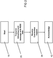
- Fig 2 shows the sequences of steps carried out by the slave 8
- Fig. 3 shows the exchange of messages between the master 2 and slave 8
- Fig. 4 shows the sequence of steps carried out by the master 2.
- the process starts with the slave device 8 wanting to connect to the master 2.
- the slave device 8 transmits at step 20 an Advertisement message 22 which includes an additional data value representing RSSI data. This is part of the universally unique identifier (UUID) data transmitted with the polling message.
- UUID universally unique identifier
- This indicates to the master the minimum signal strength specified by the slave for a connection to be established.
- This is received by the master 2 at step 24 (see Fig. 4 ).
- the master device 2 the measures the received signal strength.
- the presence of the extra data value in the Advertisement message causes the master at step 28 to compare the measured signal strength against the threshold specified by the RSSI data value from the Advertisement message.
- the master device If the RSSI is too low the master 2 ignores the Advertisement message 22 (step 30) but if it exceeds the threshold, the master device transmits a Connection request 32 at step 34. This is received by the slave at step 38 which responds with an Acknowledgement message 40 at step 42. Once the master 8 receives the Acknowledgement message 40 at step 44 a connection 46 is considered established and messages and data can be exchanged, even if the signal strength should now be reduced (subject to error rates staying within specification).
- a master and slave device operating under the Bluetooth Low Energy (TM) protocol can easily and quickly become connected simply by bringing them into close proximity with one another so that the master device receives a high signal strength.
- TM Bluetooth Low Energy
- FIG. 5 A further embodiment of the invention is described below with reference to Fig. 5 .
- a proximity determining procedure similar to that set out above is used when the master 2 and slave 8 are already in a connection.
- the master 2 transmits a polling message 48 to the slave 8 including UUID
- the master 2 polls the slave 8 with an ordinary polling message 54 and the slave replies with another message 56 which includes UUID
- NACK negative acknowledgement
Landscapes
- Engineering & Computer Science (AREA)
- Computer Networks & Wireless Communication (AREA)
- Signal Processing (AREA)
- Databases & Information Systems (AREA)
- Mobile Radio Communication Systems (AREA)
- Detection And Prevention Of Errors In Transmission (AREA)
Description
- This invention relates to radio communications between two devices, particularly where the communication follows a standard protocol such as Bluetooth (TM) or Bluetooth Low Energy (TM).
- In many radio communication protocols such as Bluetooth, it is necessary to exchange message between devices in order to establish a connection in accordance with the protocol. As it is necessary to ensure that a connection is established only if that is what the user of one or both devices wants to do, it will often be necessary for the user to take positive steps to initiate and authorise the connection. Depending on the application and the device this process may be confusing or fiddly for the user.
-
US 2013/260688 (Palin et al. ) discloses a method in which two devices initiate a communication connection upon manual intervention from a user. -
US 8,520,586 (Husted et. al) discloses a method for reducing interference associated with communication by multiple collocated wireless devices. -
US 2012/003932 (Zhodzishsky ) discloses a method in which a Bluetooth® host device can set up proximity trigger ranges. -
US 2012/289159 (Palin et al. ) discloses a method for expediting connection establishment with groups of apparatuses if they meet criteria for multiple selection. - It has been proposed that connection in a standard communication protocol could be established using another communication medium, such as by using Near Field Communication (NFC) technology. Since NFC requires that devices are brought into close physical proximity with one another in order to exchange data through mutual magnetic induction, this may be a good way to dispense with the steps requiring user intervention in the connection procedure whilst ensuring that connection only takes place when required. However there is a significant disadvantage in this approach in that additional hardware is required such as a separate antenna on both devices and driving circuitry. Thus adds to the overall cost and power consumption and makes it impractical to supply as an integrated System on Chip (SoC) product.
- As outlined above,
US 2013/260688 (Palin et al. ) discloses a method in which two devices initiate a communication connection upon manual intervention from a user, whileUS 8,520,586 (Husted et. al) discloses a method for reducing interference associated with communication by multiple collocated wireless devices. The Applicant has appreciated that it would be desirable to provide for automatic establishment of a connection between two devices. - This is achieved by the subject matter of the appended claims.
- When viewed from a first aspect the invention provides a method of digital radio communication between a first device and a second device, each comprising a radio transmitter and a radio receiver, the method comprising:
- the first device transmitting a first message to said second device comprising a data value;
- the second device receiving said first message and determining whether said data value is present;
- the second device determining a received signal strength associated with said first message; and
- the second device comparing said received signal strength to a threshold if it determines that said data value is present;
- characterised by:
the second device transmitting a second message to the first device only if said received signal strength exceeds said threshold. - The invention also extends to a digital radio communication system comprising a first device and a second device, each comprising a radio transmitter and a radio receiver, the first device being arranged to transmit a first message to said second device comprising a data value; the second device being arranged to:
- receive said first message and determine whether said data value is present;
- determine a received signal strength associated with said first message; and
- compare said received signal strength to a threshold if it determines that said data value is present;
- characterised in that:
the second device is further arranged to transmit a second message to the first device only if said received signal strength exceeds said threshold. - The invention also extends to a device for digital radio communication comprising a radio transmitter and a radio receiver, the device being arranged to:
- receive a first message from another device and determine whether a data value is present;
- determine a received signal strength associated with said first message; and
- compare said received signal strength to a threshold if it determines that said data value is present;
- characterised in that:
the device is further arranged to transmit a second message to the other device only if said received signal strength exceeds said threshold. - The invention also extends to a non-transitory computer-readable medium comprising instructions that when executed by a computer cause the computer to perform a method of:
- receiving a first message from a device and determining whether a data value is present in said first message;
- determining a received signal strength associated with said first message; and
- comparing said received signal strength to a threshold if it determines that said data value is present;
- characterised by:
transmitting a second message to the other device only if said received signal strength exceeds said threshold. - The invention further extends to a computer software product comprising the instructions set out above. The skilled person will appreciate that the aforementioned computer may be a microprocessor in a digital radio communication device, which may be portable.
- Thus it will be seen by those skilled in the art that at least some types of wireless communication between the first and second devices may be restricted to circumstances where the signal from the first device to the second device is relatively strong. The data value provides an indication to the second device that this function should be applied.
- If the received signal strength is not above the threshold then the second device could simply not transmit a message, or it could transmit a different message, For example in this case the second device may transmit a negative acknowledgement message (commonly referred to as a 'NACK').
- An example of how this function could be used would be during the establishment a connection between the two devices. The connection could therefore take place only where the received signal strength is above the threshold. This could permit, for example, a simplified connection protocol when the first and second device are physically close to one another. In such embodiments therefore the first and second messages may comprise part of a pre-determined connection establishment protocol.
- The first and second device may be arranged to operate under a pre-defined communication protocol such as Bluetooth® or Bluetooth Low Energy@. For example in a set of embodiments they may operate a protocol compatible with Bluetooth Low Energy specification 4.0 or higher. The functionality described herein therefore represents an extension to the core Bluetooth Low Energy@ specification and the data value specified above can act to confirm to the second device that the first device is compatible with the extended specification and that the extended functionality should be employed.
- The data value could simply constitute a flag indicating that the second device should employ the signal-strength-dependent transmission described herein, with the threshold to be applied by the second device when carrying out its signal strength comparison being predetermined - e.g. in a protocol - or determined from elsewhere. In a preferred set of embodiments however the data value comprises information relating to the received signal strength threshold to be applied by the second device. This allows the first device to control the procedure by determining how close it needs to be to the second device (and thus how strong the received signal needs to be) in order for the second device to respond.
- Such an arrangement is novel and inventive in its own right and thus when viewed from a further aspect the invention provides a device for digital radio communication comprising a radio transmitter and a radio receiver, the device being arranged to transmit a first message to another device comprising a data value wherein said data value comprises a signal strength threshold which said other device is expected to apply in deciding how to reply to said first message.
- In accordance with any aspect of the invention absence of the data value (leading to the second device not performing the RSSI threshold check) could be represented simply by no data being transmitted in a relevant part of the first message (such as at the end), by the transmission of null data, by the transmission of one or more values predetermined to correspond to a null value or to the transmission of data not predetermined to be valid. It follows that there may be more than one candidate data values which trigger the RSSI threshold check in the second device. Indeed this will be the case in the preferred embodiments in which the data value carries the RSSI threshold to be used by the second device.
- The first device may be a slave device - e.g. a Bluetooth-compatible Peripheral device. The second device may be a master device - e.g. a Bluetooth-compatible Central device. The first message may be an advertisement message. In one set of embodiments the first message comprises a UUID||ServiceData message including the data value such as the received signal strength information.
- The first device may also determine a signal strength it receives from the second device and use said signal strength to restrict communication, or at least some types of communication, to circumstances where the signal is relatively strong. In a set of embodiments therefore the first device is arranged only to acknowledge or respond to a message from the second device (which may be said second message or a further message) if said signal strength exceeds a threshold. This could be carried out routinely or only if the message from the second device contains a data value. Thus the first and second devices could act reciprocally.
- The message may be a polling or advertisement message - e.g. indicating a desire to connect or pair. Alternatively it may be an acknowledgement of a message received from the second device.
- The first device may be a Peripheral device and the second device may be a Central device; or the first device could be a Central device.
- As previously mentioned the invention advantageously permits in certain circumstances two devices to perform a connection procedure automatically if they are brought sufficiently close to one another. Such an arrangement is novel in its own right and thus when viewed from a further aspect the invention provides a method of establishing a connection between a first device and a second device, each comprising a radio transmitter and a radio receiver, the method comprising: one of said first and second devices determining a received signal strength for a signal transmitted between the devices using the respective radio transmitter and receivers and the devices automatically carrying out a pre-defined communication establishment protocol to establish a two-way communication connection using said radio transmitters and receivers if said received signal strength exceeds a predetermined threshold.
- An embodiment of the invention will now be described, by way of example only, with reference to the accompanying drawings in which:
-
Fig. 1 is a generalised illustration showing a first and second device communicating with one another; -
Fig. 2 is a flowchart of the procedure followed by the slave device in accordance with an embodiment of the invention; -
Fig. 3 is a schematic illustration of the messages exchanged between the master and slave devices in the embodiment described with reference toFig. 2 ; -
Fig. 4 is a flowchart of the procedure followed by the master device in accordance with the embodiment described with reference toFigs. 2 and3 ; and -
Fig. 5 is a flowchart of a procedure in accordance with another embodiment of the invention. -
Fig. 1 shows a master device 2 (also known as a Central device) having aradio transmitter section 4 and aradio receiver section 6; and a slave device 8 (also known as a Peripheral device) also having aradio transmitter section 10 and aradio receiver section 12. Linked to the firstradio receiver section 6 is a Received Signal Strength Indicator (RSSI)module 14 which is able to determine an absolute value for the strength of signals received. Similarly asecond RSSI module 16 is linked to thesecond receiver section 12. - Apart from where specified to the contrary hereinbelow the Master and
Slave devices -
Figs. 2 ,3 and4 illustrate operation in accordance with an embodiment of the invention.Fig 2 . shows the sequences of steps carried out by theslave 8,Fig. 3 shows the exchange of messages between themaster 2 andslave 8 andFig. 4 shows the sequence of steps carried out by themaster 2. Atstep 18 the process starts with theslave device 8 wanting to connect to themaster 2. Theslave device 8 then transmits atstep 20 anAdvertisement message 22 which includes an additional data value representing RSSI data. This is part of the universally unique identifier (UUID) data transmitted with the polling message. This indicates to the master the minimum signal strength specified by the slave for a connection to be established. This is received by themaster 2 at step 24 (seeFig. 4 ). Atstep 26 themaster device 2 the measures the received signal strength. - The presence of the extra data value in the Advertisement message causes the master at
step 28 to compare the measured signal strength against the threshold specified by the RSSI data value from the Advertisement message. - If the RSSI is too low the
master 2 ignores the Advertisement message 22 (step 30) but if it exceeds the threshold, the master device transmits aConnection request 32 atstep 34. This is received by the slave atstep 38 which responds with anAcknowledgement message 40 atstep 42. Once themaster 8 receives theAcknowledgement message 40 at step 44 aconnection 46 is considered established and messages and data can be exchanged, even if the signal strength should now be reduced (subject to error rates staying within specification). - Thus it will be seen that in accordance with the embodiment set out above, a master and slave device operating under the Bluetooth Low Energy (TM) protocol can easily and quickly become connected simply by bringing them into close proximity with one another so that the master device receives a high signal strength. This gives an elegant way of enabling automatic proximity connection establishment without the need for additional hardware or software such as is required for Near Field Communication.
- A further embodiment of the invention is described below with reference to
Fig. 5 . In this embodiment a proximity determining procedure similar to that set out above is used when themaster 2 andslave 8 are already in a connection. - During the connection, the
master 2 transmits apolling message 48 to theslave 8 including UUID||RSSI data within the polling message. This is received by theslave 8 which then proceeds to determine the received signal strength of themessage 48. The result is tested against the threshold specified in the RSSI data in thepolling message 48. If the signal is too weak, then thepolling message 48 is ignored but if the signal is strong enough theslave 8 issues amessage 50 in reply. - Some time later the
master 2 polls theslave 8 with anordinary polling message 54 and the slave replies with anothermessage 56 which includes UUID||RSSI data. Consequently the master performs an RSSI threshold check based on the data included the message. In this example the received signal strength is found to be below the specified threshold. Themaster 2 could just ignore the message and thus the connection would eventually be broken after the connection supervision timer has expired. Alternatively however, as shown themaster 2 sends a negative acknowledgement (NACK) 58 to theslave 8 so that the slave knows that the message is not being acted upon. This however is sufficient to keep the connection alive. - It may be appreciated from this embodiment therefore that the principle of exchanging messages only if the received signal strength is high enough may be used for any messages that are exchanged within a connection, not just for establishing the connection.
- It will be appreciated by those skilled in the art that whilst specific embodiments of the invention have been described, many variants and alternatives are possible within the scope of the invention. For example it will of course be appreciated that the procedures set out in the two embodiments can be employed together in the same device or method. Equally, although the embodiments have been described with reference to the Bluetooth Low Energy protocol, the principles may be applied to any other communication protocol.
Claims (15)
- A method of digital radio communication between a first device (8) and a second device (2), each comprising a radio transmitter (4, 10) and a radio receiver (6, 12), the method comprising:the first device (8) transmitting a first message (22) to said second device (2) comprising a data value, wherein the data value provides an indication to the second device to employ the signal strength dependent transmission;the second device (2) receiving said first message (22) and determining whether said data value is present;the second device (2) determining a received signal strength associated with said message (22);the second device (2) comparing said received signal strength to a threshold if it determines that said data value is present; andthe second device (2) transmitting a second message (32) to the first device (8) only if said received signal strength exceeds said threshold.
- A method as claimed in claim 1 wherein the first and second devices (2, 8) operate under a pre-defined communication protocol such as Bluetooth® or Bluetooth Low Energy@.
- A method as claimed in claim 1 or 2 wherein the data value comprises information relating to the received signal strength threshold to be applied by the second device (2).
- A method as claimed in any preceding claim wherein the first message (22) is an advertisement message (24).
- A method as claimed in any preceding claim wherein said first and second messages (22, 32) comprise part of a pre-defined connection establishment protocol.
- A method as claimed in any preceding claim wherein the first device (8) also determines a signal strength associated with a message from the second device and is arranged only to acknowledge or respond to said second message (32) or a further message from the second device (2) if said signal strength exceeds a threshold.
- A digital radio communication system comprising a first device (8) and a second device (2), each comprising a radio transmitter (4, 10) and a radio receiver (6, 12), the first device (8) being arranged to transmit a first message (22) to said second device (2) comprising a data value; the second device (2) being arranged to:receive said first message (22) and determine whether said data value is present, wherein the data value provides an indication to the second device to employ the signal strength dependent transmission;determine a received signal strength associated with said first message (22);compare said received signal strength to a threshold if it determines that said data value is present; andthe second device (2) is further arranged to transmit a second message (32) to the first device (8) only if said received signal strength exceeds said threshold.
- A system as claimed in claim 7 wherein the first device (8) also determines a signal strength and is arranged only to acknowledge or respond to said second message (32) or a further message from the second device (2) if said signal strength exceeds a threshold.
- A device (2) for digital radio communication comprising a radio transmitter (4) and a radio receiver (6), the device being arranged to:receive a first message (22) from another device (8) and determine whether a data value is present, wherein the data value provides an indication to the second device to employ the signal strength dependent transmission;determine a received signal strength associated with said first message (22);compare said received signal strength to a threshold if it determines that said data value is present; andthe device (2) is further arranged to transmit a second message (32) to the other device (8) only if said received signal strength exceeds said threshold.
- A system or device (2) as claimed in claim 7, 8 or 9 wherein the device (2) or the first and second devices (2, 8) operate(s) under a pre-defined communication protocol such as Bluetooth® or Bluetooth Low Energy@.
- A system or device (2) as claimed in any one of claims 7 to 10 wherein the data value comprises information relating to the received signal strength threshold to be applied by the other device (8).
- A system or device as claimed in any of claims 7 to 11 wherein the first message (22) is an advertisement message.
- A system or device (2) as claimed in any of claims 7 to 12 wherein said first and second messages (22, 32) comprise part of a pre-defined connection establishment protocol.
- A computer software product comprising instructions that when executed by a computer cause the computer to perform a method of:receiving a first message (22) from a device (8) and determining whether a data value is present in said message (22), wherein the data value provides an indication to the second device to employ the signal strength dependent transmission;determining a received signal strength associated with said first message (22);comparing said received signal strength to a threshold if it determines that said data value is present; andtransmitting a second message (32) to the other device (8) only if said received signal strength exceeds said threshold.
- A non-transitory computer-readable medium having stored thereon the computer software product as claimed in claim 14 wherein said method comprises the features of any one of claims 2 to 6.
Priority Applications (4)
| Application Number | Priority Date | Filing Date | Title |
|---|---|---|---|
| PCT/GB2014/053652 WO2015092366A1 (en) | 2013-12-16 | 2014-12-10 | Radio communications |
| KR1020167018952A KR20160099647A (en) | 2013-12-16 | 2014-12-10 | Radio communications |
| JP2016539909A JP2017511984A (en) | 2013-12-16 | 2014-12-10 | Wireless communication |
| CN201480068523.8A CN105830472A (en) | 2013-12-16 | 2014-12-10 | radio communication |
Applications Claiming Priority (1)
| Application Number | Priority Date | Filing Date | Title |
|---|---|---|---|
| GB1322196.5A GB2521224A (en) | 2013-12-16 | 2013-12-16 | Radio communications |
Publications (2)
| Publication Number | Publication Date |
|---|---|
| EP2884814A1 EP2884814A1 (en) | 2015-06-17 |
| EP2884814B1 true EP2884814B1 (en) | 2020-04-15 |
Family
ID=49918462
Family Applications (1)
| Application Number | Title | Priority Date | Filing Date |
|---|---|---|---|
| EP13199432.9A Active EP2884814B1 (en) | 2013-12-16 | 2013-12-23 | Radio communications |
Country Status (8)
| Country | Link |
|---|---|
| US (1) | US20150172934A1 (en) |
| EP (1) | EP2884814B1 (en) |
| JP (1) | JP2017511984A (en) |
| KR (1) | KR20160099647A (en) |
| CN (1) | CN105830472A (en) |
| GB (1) | GB2521224A (en) |
| TW (1) | TW201526696A (en) |
| WO (1) | WO2015092366A1 (en) |
Families Citing this family (17)
| Publication number | Priority date | Publication date | Assignee | Title |
|---|---|---|---|---|
| CA2826433C (en) | 2011-02-14 | 2022-05-31 | Brenda S. Morse | Micronized placental tissue compositions and methods of making and using the same |
| US8989053B1 (en) | 2013-11-29 | 2015-03-24 | Fedex Corporate Services, Inc. | Association management in a wireless node network |
| KR102201616B1 (en) * | 2014-02-23 | 2021-01-12 | 삼성전자주식회사 | Method of Searching Device Between Electrical Devices |
| US10453023B2 (en) | 2014-05-28 | 2019-10-22 | Fedex Corporate Services, Inc. | Methods and node apparatus for adaptive node communication within a wireless node network |
| US10339496B2 (en) | 2015-06-15 | 2019-07-02 | Milwaukee Electric Tool Corporation | Power tool communication system |
| US10057133B2 (en) * | 2015-07-08 | 2018-08-21 | Fedex Corporate Services, Inc. | Systems, apparatus, and methods of enhanced monitoring for an event candidate associated with cycling power of an ID node within a wireless node network |
| GB201516673D0 (en) | 2015-09-21 | 2015-11-04 | Nicoventures Holdings Ltd | Topology |
| CN108780538A (en) | 2016-03-23 | 2018-11-09 | 联邦快递服务公司 | Systems, devices and methods for self-adjusting broadcast settings of nodes in a network of wireless nodes |
| US9807570B1 (en) * | 2016-06-01 | 2017-10-31 | GM Global Technology Operations LLC | Systems and methods for detecting proximity and location of a smartphone or other device to a vehicle |
| TWM555274U (en) | 2016-06-06 | 2018-02-11 | 米沃奇電子工具公司 | Mobile device for connection to a power tool device |
| US11622392B2 (en) | 2016-06-06 | 2023-04-04 | Milwaukee Electric Tool Corporation | System and method for establishing a wireless connection between power tool and mobile device |
| GB201707050D0 (en) | 2017-05-03 | 2017-06-14 | British American Tobacco Investments Ltd | Data communication |
| GB201722241D0 (en) | 2017-12-29 | 2018-02-14 | British American Tobacco Investments Ltd | Data capture across devices |
| GB201722278D0 (en) | 2017-12-29 | 2018-02-14 | British American Tobacco Investments Ltd | Device identification and method |
| GB201801146D0 (en) | 2018-01-24 | 2018-03-07 | Nicoventures Trading Ltd | Aerosol source for a vapour provision system |
| CN111800836B (en) | 2020-06-30 | 2024-01-16 | 北京小米移动软件有限公司 | A communication method, device, electronic equipment and storage medium |
| EP4385136A1 (en) * | 2021-09-24 | 2024-06-19 | Apple Inc. | Adjustment of radio frequency settings of near-field communication circuitry |
Family Cites Families (19)
| Publication number | Priority date | Publication date | Assignee | Title |
|---|---|---|---|---|
| GB2339994B (en) * | 1998-07-25 | 2000-10-11 | Motorola Ltd | Radio communication system |
| US7174130B2 (en) * | 2001-09-12 | 2007-02-06 | Agere Systems Inc. | Security apparatus and method during BLUETOOTH pairing |
| CN101692127B (en) * | 2009-09-30 | 2011-08-24 | 西安电子科技大学 | Radio frequency SIM card range measurement system and measurement method based on near-field array range estimation |
| US8520586B1 (en) * | 2009-12-16 | 2013-08-27 | Qualcomm Incorporated | Discovery and connection coexistence mechanism for wireless devices |
| CN102215051B (en) * | 2010-04-02 | 2013-08-28 | 国民技术股份有限公司 | Method for determining distance threshold in process of starting transaction by virtue of radio frequency SIM (subscriber identity model) card based on low-frequency magnetic communication |
| US20120003932A1 (en) * | 2010-07-01 | 2012-01-05 | Victor Zhodzishsky | Method and system for reducing power consumption in bluetooth proximity implementations |
| JP5204811B2 (en) * | 2010-07-30 | 2013-06-05 | 株式会社バッファロー | COMMUNICATION DEVICE FOR RADIO COMMUNICATION, RADIO COMMUNICATION SYSTEM, AND METHOD FOR RADIO COMMUNICATION |
| KR101694773B1 (en) * | 2010-08-05 | 2017-01-23 | 삼성전자주식회사 | Method and apparatus for connecting wireless network in a digital device |
| US8929816B2 (en) * | 2011-05-13 | 2015-01-06 | Nokia Corporation | Multiple apparatus selection via touch |
| US8622836B2 (en) * | 2011-12-22 | 2014-01-07 | Igt | Use of wireless signal strength to determine connection |
| US9380550B2 (en) * | 2012-03-07 | 2016-06-28 | Lg Electronics Inc. | Method for checking availability or state of peer entity |
| US8879993B2 (en) * | 2012-03-30 | 2014-11-04 | Nokia Corporation | Method, apparatus, and computer program product for wireless short-range communication establishment |
| US9629646B2 (en) * | 2012-07-11 | 2017-04-25 | Jens Kather | Curved burr surgical instrument |
| US9436192B2 (en) * | 2012-08-01 | 2016-09-06 | Futurewei Technologies, Inc. | Apparatus for PWM gate drive circuit |
| WO2014027436A1 (en) * | 2012-08-17 | 2014-02-20 | ソフトバンクモバイル株式会社 | Communication device, communication method, communication system, and program |
| US9137766B2 (en) * | 2012-10-26 | 2015-09-15 | Qualcomm Incorporated | Systems and methods for synchronization of wireless devices in a peer-to-peer network |
| US20140274031A1 (en) * | 2013-03-13 | 2014-09-18 | Qualcomm Incorporated | Sharing data among proximate mobile devices with short-range wireless signals |
| US9521695B2 (en) * | 2013-06-04 | 2016-12-13 | Tallac Networks, Inc. | Initializing network advertisements from probe requests |
| EP2821118B1 (en) * | 2013-07-02 | 2018-10-17 | Pall Corporation | Dual bag filter |
-
2013
- 2013-12-16 GB GB1322196.5A patent/GB2521224A/en not_active Withdrawn
- 2013-12-23 US US14/139,661 patent/US20150172934A1/en not_active Abandoned
- 2013-12-23 EP EP13199432.9A patent/EP2884814B1/en active Active
-
2014
- 2014-12-01 TW TW103141653A patent/TW201526696A/en unknown
- 2014-12-10 WO PCT/GB2014/053652 patent/WO2015092366A1/en not_active Ceased
- 2014-12-10 KR KR1020167018952A patent/KR20160099647A/en not_active Withdrawn
- 2014-12-10 JP JP2016539909A patent/JP2017511984A/en active Pending
- 2014-12-10 CN CN201480068523.8A patent/CN105830472A/en active Pending
Non-Patent Citations (1)
| Title |
|---|
| None * |
Also Published As
| Publication number | Publication date |
|---|---|
| TW201526696A (en) | 2015-07-01 |
| CN105830472A (en) | 2016-08-03 |
| GB2521224A (en) | 2015-06-17 |
| KR20160099647A (en) | 2016-08-22 |
| GB201322196D0 (en) | 2014-01-29 |
| JP2017511984A (en) | 2017-04-27 |
| EP2884814A1 (en) | 2015-06-17 |
| US20150172934A1 (en) | 2015-06-18 |
| WO2015092366A1 (en) | 2015-06-25 |
Similar Documents
| Publication | Publication Date | Title |
|---|---|---|
| EP2884814A1 (en) | Radio communications | |
| CN114630305B (en) | Devices, systems, and methods for establishing bidirectional links between devices. | |
| EP2798887B1 (en) | Low cost proximity pairing mechanism in wireless personal area networks | |
| EP2628233B1 (en) | Power transmitter and power receiver for an inductive power system | |
| JP2022130669A5 (en) | ||
| KR20160114642A (en) | Using visible light communication to manage wireless communications between devices | |
| JP2008545312A (en) | RFID capability optimization negotiation | |
| US20230052957A1 (en) | Method, apparatus, and computer program for connectionless asset tracking in wireless communication system, and recording medium thereof | |
| JP2020089135A5 (en) | ||
| KR20160017028A (en) | Digital radio communication | |
| JP2015088788A5 (en) | ||
| JP2011514774A5 (en) | ||
| JP2015513341A5 (en) | ||
| WO2009104801A4 (en) | Power line communication apparatus, power line communication system, and registration processing method | |
| CN103824039B (en) | RFID accurate positioning method | |
| CN117134843A (en) | Bidirectional wireless sensing measurement method, device, equipment and storage medium | |
| JP2017169408A (en) | Power transmission device, power transmission device control method, and program | |
| KR102083684B1 (en) | Method for connecting a vehicle and wireless machines | |
| EP3061281B1 (en) | Coupling devices using multiple discovery zones | |
| WO2017213807A1 (en) | Device pairing using a secure zone | |
| CN107465487B (en) | Bus data sending method, system and sub-equipment | |
| WO2018032507A1 (en) | Methods and systems for adding device to sequential personal area network chain | |
| US20240406828A1 (en) | Wireless communication method and system | |
| CN111179571A (en) | System comprising a medical device and a remote control | |
| CN107613573B (en) | Wireless audio reproducing apparatus and communication method thereof |
Legal Events
| Date | Code | Title | Description |
|---|---|---|---|
| PUAI | Public reference made under article 153(3) epc to a published international application that has entered the european phase |
Free format text: ORIGINAL CODE: 0009012 |
|
| 17P | Request for examination filed |
Effective date: 20131223 |
|
| AK | Designated contracting states |
Kind code of ref document: A1 Designated state(s): AL AT BE BG CH CY CZ DE DK EE ES FI FR GB GR HR HU IE IS IT LI LT LU LV MC MK MT NL NO PL PT RO RS SE SI SK SM TR |
|
| AX | Request for extension of the european patent |
Extension state: BA ME |
|
| R17P | Request for examination filed (corrected) |
Effective date: 20151217 |
|
| RBV | Designated contracting states (corrected) |
Designated state(s): AL AT BE BG CH CY CZ DE DK EE ES FI FR GB GR HR HU IE IS IT LI LT LU LV MC MK MT NL NO PL PT RO RS SE SI SK SM TR |
|
| STAA | Information on the status of an ep patent application or granted ep patent |
Free format text: STATUS: EXAMINATION IS IN PROGRESS |
|
| 17Q | First examination report despatched |
Effective date: 20180910 |
|
| REG | Reference to a national code |
Ref country code: DE Ref legal event code: R079 Ref document number: 602013067890 Country of ref document: DE Free format text: PREVIOUS MAIN CLASS: H04W0084200000 Ipc: H04W0008000000 |
|
| GRAP | Despatch of communication of intention to grant a patent |
Free format text: ORIGINAL CODE: EPIDOSNIGR1 |
|
| STAA | Information on the status of an ep patent application or granted ep patent |
Free format text: STATUS: GRANT OF PATENT IS INTENDED |
|
| RIC1 | Information provided on ipc code assigned before grant |
Ipc: H04W 8/00 20090101AFI20190924BHEP Ipc: H04W 76/10 20180101ALI20190924BHEP Ipc: H04W 84/20 20090101ALN20190924BHEP Ipc: H04W 76/14 20180101ALI20190924BHEP |
|
| INTG | Intention to grant announced |
Effective date: 20191028 |
|
| GRAS | Grant fee paid |
Free format text: ORIGINAL CODE: EPIDOSNIGR3 |
|
| GRAA | (expected) grant |
Free format text: ORIGINAL CODE: 0009210 |
|
| STAA | Information on the status of an ep patent application or granted ep patent |
Free format text: STATUS: THE PATENT HAS BEEN GRANTED |
|
| AK | Designated contracting states |
Kind code of ref document: B1 Designated state(s): AL AT BE BG CH CY CZ DE DK EE ES FI FR GB GR HR HU IE IS IT LI LT LU LV MC MK MT NL NO PL PT RO RS SE SI SK SM TR |
|
| REG | Reference to a national code |
Ref country code: GB Ref legal event code: FG4D Ref country code: CH Ref legal event code: EP |
|
| REG | Reference to a national code |
Ref country code: DE Ref legal event code: R096 Ref document number: 602013067890 Country of ref document: DE |
|
| REG | Reference to a national code |
Ref country code: IE Ref legal event code: FG4D |
|
| REG | Reference to a national code |
Ref country code: AT Ref legal event code: REF Ref document number: 1258718 Country of ref document: AT Kind code of ref document: T Effective date: 20200515 |
|
| REG | Reference to a national code |
Ref country code: NL Ref legal event code: MP Effective date: 20200415 |
|
| REG | Reference to a national code |
Ref country code: LT Ref legal event code: MG4D |
|
| PG25 | Lapsed in a contracting state [announced via postgrant information from national office to epo] |
Ref country code: LT Free format text: LAPSE BECAUSE OF FAILURE TO SUBMIT A TRANSLATION OF THE DESCRIPTION OR TO PAY THE FEE WITHIN THE PRESCRIBED TIME-LIMIT Effective date: 20200415 Ref country code: NL Free format text: LAPSE BECAUSE OF FAILURE TO SUBMIT A TRANSLATION OF THE DESCRIPTION OR TO PAY THE FEE WITHIN THE PRESCRIBED TIME-LIMIT Effective date: 20200415 Ref country code: PT Free format text: LAPSE BECAUSE OF FAILURE TO SUBMIT A TRANSLATION OF THE DESCRIPTION OR TO PAY THE FEE WITHIN THE PRESCRIBED TIME-LIMIT Effective date: 20200817 Ref country code: SE Free format text: LAPSE BECAUSE OF FAILURE TO SUBMIT A TRANSLATION OF THE DESCRIPTION OR TO PAY THE FEE WITHIN THE PRESCRIBED TIME-LIMIT Effective date: 20200415 Ref country code: FI Free format text: LAPSE BECAUSE OF FAILURE TO SUBMIT A TRANSLATION OF THE DESCRIPTION OR TO PAY THE FEE WITHIN THE PRESCRIBED TIME-LIMIT Effective date: 20200415 Ref country code: IS Free format text: LAPSE BECAUSE OF FAILURE TO SUBMIT A TRANSLATION OF THE DESCRIPTION OR TO PAY THE FEE WITHIN THE PRESCRIBED TIME-LIMIT Effective date: 20200815 Ref country code: GR Free format text: LAPSE BECAUSE OF FAILURE TO SUBMIT A TRANSLATION OF THE DESCRIPTION OR TO PAY THE FEE WITHIN THE PRESCRIBED TIME-LIMIT Effective date: 20200716 Ref country code: NO Free format text: LAPSE BECAUSE OF FAILURE TO SUBMIT A TRANSLATION OF THE DESCRIPTION OR TO PAY THE FEE WITHIN THE PRESCRIBED TIME-LIMIT Effective date: 20200715 |
|
| REG | Reference to a national code |
Ref country code: AT Ref legal event code: MK05 Ref document number: 1258718 Country of ref document: AT Kind code of ref document: T Effective date: 20200415 |
|
| PG25 | Lapsed in a contracting state [announced via postgrant information from national office to epo] |
Ref country code: RS Free format text: LAPSE BECAUSE OF FAILURE TO SUBMIT A TRANSLATION OF THE DESCRIPTION OR TO PAY THE FEE WITHIN THE PRESCRIBED TIME-LIMIT Effective date: 20200415 Ref country code: BG Free format text: LAPSE BECAUSE OF FAILURE TO SUBMIT A TRANSLATION OF THE DESCRIPTION OR TO PAY THE FEE WITHIN THE PRESCRIBED TIME-LIMIT Effective date: 20200715 Ref country code: LV Free format text: LAPSE BECAUSE OF FAILURE TO SUBMIT A TRANSLATION OF THE DESCRIPTION OR TO PAY THE FEE WITHIN THE PRESCRIBED TIME-LIMIT Effective date: 20200415 Ref country code: HR Free format text: LAPSE BECAUSE OF FAILURE TO SUBMIT A TRANSLATION OF THE DESCRIPTION OR TO PAY THE FEE WITHIN THE PRESCRIBED TIME-LIMIT Effective date: 20200415 |
|
| PG25 | Lapsed in a contracting state [announced via postgrant information from national office to epo] |
Ref country code: AL Free format text: LAPSE BECAUSE OF FAILURE TO SUBMIT A TRANSLATION OF THE DESCRIPTION OR TO PAY THE FEE WITHIN THE PRESCRIBED TIME-LIMIT Effective date: 20200415 |
|
| REG | Reference to a national code |
Ref country code: DE Ref legal event code: R097 Ref document number: 602013067890 Country of ref document: DE |
|
| PG25 | Lapsed in a contracting state [announced via postgrant information from national office to epo] |
Ref country code: CZ Free format text: LAPSE BECAUSE OF FAILURE TO SUBMIT A TRANSLATION OF THE DESCRIPTION OR TO PAY THE FEE WITHIN THE PRESCRIBED TIME-LIMIT Effective date: 20200415 Ref country code: RO Free format text: LAPSE BECAUSE OF FAILURE TO SUBMIT A TRANSLATION OF THE DESCRIPTION OR TO PAY THE FEE WITHIN THE PRESCRIBED TIME-LIMIT Effective date: 20200415 Ref country code: DK Free format text: LAPSE BECAUSE OF FAILURE TO SUBMIT A TRANSLATION OF THE DESCRIPTION OR TO PAY THE FEE WITHIN THE PRESCRIBED TIME-LIMIT Effective date: 20200415 Ref country code: IT Free format text: LAPSE BECAUSE OF FAILURE TO SUBMIT A TRANSLATION OF THE DESCRIPTION OR TO PAY THE FEE WITHIN THE PRESCRIBED TIME-LIMIT Effective date: 20200415 Ref country code: AT Free format text: LAPSE BECAUSE OF FAILURE TO SUBMIT A TRANSLATION OF THE DESCRIPTION OR TO PAY THE FEE WITHIN THE PRESCRIBED TIME-LIMIT Effective date: 20200415 Ref country code: SM Free format text: LAPSE BECAUSE OF FAILURE TO SUBMIT A TRANSLATION OF THE DESCRIPTION OR TO PAY THE FEE WITHIN THE PRESCRIBED TIME-LIMIT Effective date: 20200415 Ref country code: EE Free format text: LAPSE BECAUSE OF FAILURE TO SUBMIT A TRANSLATION OF THE DESCRIPTION OR TO PAY THE FEE WITHIN THE PRESCRIBED TIME-LIMIT Effective date: 20200415 Ref country code: ES Free format text: LAPSE BECAUSE OF FAILURE TO SUBMIT A TRANSLATION OF THE DESCRIPTION OR TO PAY THE FEE WITHIN THE PRESCRIBED TIME-LIMIT Effective date: 20200415 |
|
| PLBE | No opposition filed within time limit |
Free format text: ORIGINAL CODE: 0009261 |
|
| STAA | Information on the status of an ep patent application or granted ep patent |
Free format text: STATUS: NO OPPOSITION FILED WITHIN TIME LIMIT |
|
| PG25 | Lapsed in a contracting state [announced via postgrant information from national office to epo] |
Ref country code: SK Free format text: LAPSE BECAUSE OF FAILURE TO SUBMIT A TRANSLATION OF THE DESCRIPTION OR TO PAY THE FEE WITHIN THE PRESCRIBED TIME-LIMIT Effective date: 20200415 Ref country code: PL Free format text: LAPSE BECAUSE OF FAILURE TO SUBMIT A TRANSLATION OF THE DESCRIPTION OR TO PAY THE FEE WITHIN THE PRESCRIBED TIME-LIMIT Effective date: 20200415 |
|
| 26N | No opposition filed |
Effective date: 20210118 |
|
| PG25 | Lapsed in a contracting state [announced via postgrant information from national office to epo] |
Ref country code: SI Free format text: LAPSE BECAUSE OF FAILURE TO SUBMIT A TRANSLATION OF THE DESCRIPTION OR TO PAY THE FEE WITHIN THE PRESCRIBED TIME-LIMIT Effective date: 20200415 |
|
| REG | Reference to a national code |
Ref country code: CH Ref legal event code: PL |
|
| PG25 | Lapsed in a contracting state [announced via postgrant information from national office to epo] |
Ref country code: MC Free format text: LAPSE BECAUSE OF FAILURE TO SUBMIT A TRANSLATION OF THE DESCRIPTION OR TO PAY THE FEE WITHIN THE PRESCRIBED TIME-LIMIT Effective date: 20200415 |
|
| REG | Reference to a national code |
Ref country code: BE Ref legal event code: MM Effective date: 20201231 |
|
| PG25 | Lapsed in a contracting state [announced via postgrant information from national office to epo] |
Ref country code: LU Free format text: LAPSE BECAUSE OF NON-PAYMENT OF DUE FEES Effective date: 20201223 Ref country code: IE Free format text: LAPSE BECAUSE OF NON-PAYMENT OF DUE FEES Effective date: 20201223 |
|
| PG25 | Lapsed in a contracting state [announced via postgrant information from national office to epo] |
Ref country code: CH Free format text: LAPSE BECAUSE OF NON-PAYMENT OF DUE FEES Effective date: 20201231 Ref country code: LI Free format text: LAPSE BECAUSE OF NON-PAYMENT OF DUE FEES Effective date: 20201231 |
|
| PG25 | Lapsed in a contracting state [announced via postgrant information from national office to epo] |
Ref country code: TR Free format text: LAPSE BECAUSE OF FAILURE TO SUBMIT A TRANSLATION OF THE DESCRIPTION OR TO PAY THE FEE WITHIN THE PRESCRIBED TIME-LIMIT Effective date: 20200415 Ref country code: MT Free format text: LAPSE BECAUSE OF FAILURE TO SUBMIT A TRANSLATION OF THE DESCRIPTION OR TO PAY THE FEE WITHIN THE PRESCRIBED TIME-LIMIT Effective date: 20200415 Ref country code: CY Free format text: LAPSE BECAUSE OF FAILURE TO SUBMIT A TRANSLATION OF THE DESCRIPTION OR TO PAY THE FEE WITHIN THE PRESCRIBED TIME-LIMIT Effective date: 20200415 |
|
| PG25 | Lapsed in a contracting state [announced via postgrant information from national office to epo] |
Ref country code: MK Free format text: LAPSE BECAUSE OF FAILURE TO SUBMIT A TRANSLATION OF THE DESCRIPTION OR TO PAY THE FEE WITHIN THE PRESCRIBED TIME-LIMIT Effective date: 20200415 |
|
| PG25 | Lapsed in a contracting state [announced via postgrant information from national office to epo] |
Ref country code: BE Free format text: LAPSE BECAUSE OF NON-PAYMENT OF DUE FEES Effective date: 20201231 |
|
| PGFP | Annual fee paid to national office [announced via postgrant information from national office to epo] |
Ref country code: DE Payment date: 20251126 Year of fee payment: 13 |
|
| PGFP | Annual fee paid to national office [announced via postgrant information from national office to epo] |
Ref country code: GB Payment date: 20251119 Year of fee payment: 13 |
|
| PGFP | Annual fee paid to national office [announced via postgrant information from national office to epo] |
Ref country code: FR Payment date: 20251120 Year of fee payment: 13 |