EP2884788A1 - Interference reduction method, wireless base station, user terminal, and wireless communication system - Google Patents
Interference reduction method, wireless base station, user terminal, and wireless communication system Download PDFInfo
- Publication number
- EP2884788A1 EP2884788A1 EP13828535.8A EP13828535A EP2884788A1 EP 2884788 A1 EP2884788 A1 EP 2884788A1 EP 13828535 A EP13828535 A EP 13828535A EP 2884788 A1 EP2884788 A1 EP 2884788A1
- Authority
- EP
- European Patent Office
- Prior art keywords
- base station
- macro
- downlink control
- cell
- control signal
- Prior art date
- Legal status (The legal status is an assumption and is not a legal conclusion. Google has not performed a legal analysis and makes no representation as to the accuracy of the status listed.)
- Withdrawn
Links
Images






Classifications
-
- H—ELECTRICITY
- H04—ELECTRIC COMMUNICATION TECHNIQUE
- H04B—TRANSMISSION
- H04B15/00—Suppression or limitation of noise or interference
-
- H—ELECTRICITY
- H04—ELECTRIC COMMUNICATION TECHNIQUE
- H04L—TRANSMISSION OF DIGITAL INFORMATION, e.g. TELEGRAPHIC COMMUNICATION
- H04L5/00—Arrangements affording multiple use of the transmission path
- H04L5/003—Arrangements for allocating sub-channels of the transmission path
- H04L5/0053—Allocation of signalling, i.e. of overhead other than pilot signals
-
- H—ELECTRICITY
- H04—ELECTRIC COMMUNICATION TECHNIQUE
- H04L—TRANSMISSION OF DIGITAL INFORMATION, e.g. TELEGRAPHIC COMMUNICATION
- H04L5/00—Arrangements affording multiple use of the transmission path
- H04L5/003—Arrangements for allocating sub-channels of the transmission path
- H04L5/0058—Allocation criteria
- H04L5/0073—Allocation arrangements that take into account other cell interferences
-
- H—ELECTRICITY
- H04—ELECTRIC COMMUNICATION TECHNIQUE
- H04W—WIRELESS COMMUNICATION NETWORKS
- H04W72/00—Local resource management
- H04W72/20—Control channels or signalling for resource management
- H04W72/23—Control channels or signalling for resource management in the downlink direction of a wireless link, i.e. towards a terminal
-
- H—ELECTRICITY
- H04—ELECTRIC COMMUNICATION TECHNIQUE
- H04L—TRANSMISSION OF DIGITAL INFORMATION, e.g. TELEGRAPHIC COMMUNICATION
- H04L1/00—Arrangements for detecting or preventing errors in the information received
- H04L1/12—Arrangements for detecting or preventing errors in the information received by using return channel
- H04L1/16—Arrangements for detecting or preventing errors in the information received by using return channel in which the return channel carries supervisory signals, e.g. repetition request signals
- H04L1/18—Automatic repetition systems, e.g. Van Duuren systems
- H04L1/1867—Arrangements specially adapted for the transmitter end
-
- H—ELECTRICITY
- H04—ELECTRIC COMMUNICATION TECHNIQUE
- H04L—TRANSMISSION OF DIGITAL INFORMATION, e.g. TELEGRAPHIC COMMUNICATION
- H04L5/00—Arrangements affording multiple use of the transmission path
- H04L5/003—Arrangements for allocating sub-channels of the transmission path
- H04L5/0048—Allocation of pilot signals, i.e. of signals known to the receiver
-
- H—ELECTRICITY
- H04—ELECTRIC COMMUNICATION TECHNIQUE
- H04W—WIRELESS COMMUNICATION NETWORKS
- H04W16/00—Network planning, e.g. coverage or traffic planning tools; Network deployment, e.g. resource partitioning or cells structures
- H04W16/24—Cell structures
- H04W16/32—Hierarchical cell structures
-
- H—ELECTRICITY
- H04—ELECTRIC COMMUNICATION TECHNIQUE
- H04W—WIRELESS COMMUNICATION NETWORKS
- H04W48/00—Access restriction; Network selection; Access point selection
- H04W48/08—Access restriction or access information delivery, e.g. discovery data delivery
- H04W48/12—Access restriction or access information delivery, e.g. discovery data delivery using downlink control channel
-
- H—ELECTRICITY
- H04—ELECTRIC COMMUNICATION TECHNIQUE
- H04W—WIRELESS COMMUNICATION NETWORKS
- H04W72/00—Local resource management
- H04W72/04—Wireless resource allocation
-
- H—ELECTRICITY
- H04—ELECTRIC COMMUNICATION TECHNIQUE
- H04W—WIRELESS COMMUNICATION NETWORKS
- H04W72/00—Local resource management
- H04W72/50—Allocation or scheduling criteria for wireless resources
- H04W72/54—Allocation or scheduling criteria for wireless resources based on quality criteria
- H04W72/541—Allocation or scheduling criteria for wireless resources based on quality criteria using the level of interference
-
- H—ELECTRICITY
- H04—ELECTRIC COMMUNICATION TECHNIQUE
- H04W—WIRELESS COMMUNICATION NETWORKS
- H04W84/00—Network topologies
- H04W84/02—Hierarchically pre-organised networks, e.g. paging networks, cellular networks, WLAN [Wireless Local Area Network] or WLL [Wireless Local Loop]
- H04W84/04—Large scale networks; Deep hierarchical networks
- H04W84/042—Public Land Mobile systems, e.g. cellular systems
- H04W84/045—Public Land Mobile systems, e.g. cellular systems using private Base Stations, e.g. femto Base Stations, home Node B
-
- H—ELECTRICITY
- H04—ELECTRIC COMMUNICATION TECHNIQUE
- H04W—WIRELESS COMMUNICATION NETWORKS
- H04W88/00—Devices specially adapted for wireless communication networks, e.g. terminals, base stations or access point devices
- H04W88/08—Access point devices
Definitions
- the present invention has been made in view of the above, and it is therefore an object of the present invention to provide an interference reduction method, a radio base station, a user terminal and a radio communication system that can reduce interference between a macro cell and a small cell in a radio communication system in which a macro cell and a small cell are arranged to overlap at least in part, such as a HetNet.
- the interference reduction method of the present invention is an interference reduction method in a small base station that forms a small cell so that at least part of the small cell overlaps with a macro cell that is formed by a macro base station, and this interference reduction method includes the steps of transmitting macro cell identification information that identifies the macro cell, to a user terminal in the small cell, allocating a downlink control signal for the user terminal to a radio resource unit having a different index number from that of a radio resource unit where a downlink control signal to be transmitted from the macro base station is allocated, and interleaving the downlink control signal for the user terminal using an interleaving pattern that is generated based on the macro cell identification information and that is same as an interleaving pattern used in the macro base station.
- the present invention in a communication system in which a macro cell and a small cell are arranged to overlap at least in part, as in a HetNet, it is possible to reduce interference between the macro cell and the small cell.
- the cell-specific scrambling sequences are, for example, determined based on equation 1.
- the cell-specific shift patterns are, for example, determined based on equation 2.
- the radio resource units, to which DCI to be transmitted by the PDCCH is allocated are control channel elements (CCEs). Also, the radio resource units, to which DCI to be transmitted by the enhanced PDCCH is allocated, are enhanced control channel elements (eCCEs). Also, the radio resource units, to which CFIs to be transmitted by the PCFICH and delivery acknowledgment information to be transmitted by the PHICH are allocated, are resource element groups (REGs). Note that an REG is formed with four resource elements (REs), and a CCE is formed with nine REGs. eCCEs may be formed with a plurality of enhanced resource element groups (eREGs), or may be formed by dividing a physical resource block (PRB) pair using at least one of frequency division, code division and time division.
- CCEs control channel elements
- eCCEs enhanced control channel elements
- PRB physical resource block
- the interference reduction method is applicable to cases where downlink control signals are the PCFICH signal, the PHICH signal, the enhanced PDCCH signal and so on, by changing radio resource units to allocate the downlink control signals to, from CCEs to REGs and eCCEs. Also, assume that the following interference reduction method is applied to the radio communication system shown in FIG. 7 .
- the small base station 12a may transmit the cell ID "X" of the macro cell C1, which is different from the subject cell(the small cell), using higher layer signaling such as RRC signaling, or may transmit the cell ID "X” using broadcast information such as MIBs (Master Information Blocks) or SIBs (System Information Blocks), to the user terminal 22.
- the cell ID "X" of the macro cell C1 may be stored in the small base station 12a in advance, or may be reported from the macro base station 11 to the small base station 12a.
- the small base station 12 allocates the PDCCH signal to CCEs having different index numbers from those of the macro base station 11, and interleaves the PDCCH signal using the same interleaving pattern as that of the macro base station 11. Consequently, since the radio resources (for example, resource elements) where the PDCCH signal is placed can be made different between the macro base station 11 and the small base station 12, it is possible to realize orthogonalization. Also, it is possible to carry out interference coordination between the PDCCH signals of the small base station and the macro base station 11 on the level of CCEs.
- the radio resources for example, resource elements
- the small base station 12 may scramble the PDCCH signal for the user terminal 22 using either the same scrambling sequence as in the macro base station 11 or a scrambling sequence that is specific to the subject station (the small base station).
- FIG. 5 is a diagram to show another example of an interference reduction method according to the present embodiment.
- the small base station 12 scrambles the PDCCH signal for the user terminal 22 using a scrambling sequence that is generated based on the cell ID of the subject cell and that is specific to the subject cell.
- the PDCCH signals in the macro base station 11 and the small base station 12 are scrambled using different scrambling sequences.
- the PDCCH signals of the macro base station 11 and the small base station 12 cannot be orthogonalized, it is still possible to randomize interference.
- FIG. 6 is a diagram to show yet another example of an interference reduction method according to the present embodiment.
- the radio base station 11 and the small base stations 12 will be referred to as a “macro base station 11" and “small base stations 12,” respectively.
- the macro base station 11 may be referred to as an “eNodeB,” a “radio base station apparatus,” a “transmission point” and so on.
- the small base stations 12 may be referred to as "pico base stations,” “femto base stations,” “Home eNodeBs,” “RRHs (Remote Radio Heads),” “micro base stations,” “transmission points,” and so on.
- the user terminals 20 are terminals supporting each communication scheme such as LTE and LTE-A, and may be not only mobile communication terminals but may also be fixed communication terminals as well.
- user terminals 20 may be referred to as "user terminals 21" when connected to the macro base station 11 and may be referred to as “user terminals 22" when connected to the small base stations 12, both have the same configurations.
- uplink signals include uplink data signals and uplink control signals.
- the uplink data signals include, for example, the PUSCH (Physical Uplink Shared CHannel) signal to transmit user data and uplink layer control information.
- the uplink control signals include, for example, the PUCCH (Physical Uplink Control CHannel) signal, which transmits downlink channel state information (CSI) and delivery acknowledgment information (ACK/NACK/DTX), and so on.
- PUSCH Physical Uplink Shared CHannel
- PUCCH Physical Uplink Control CHannel
- CSI downlink channel state information
- ACK/NACK/DTX delivery acknowledgment information
- FIG. 8 is a diagram of an overall structure of the small base station 12 according to the present embodiment.
- the small base station 12 includes a plurality of transmitting/receiving antennas 101 for MIMO transmission, amplifying sections 102, transmitting/receiving sections 103 (transmitting sections), a baseband signal processing section 104, a call processing section 105 and a transmission path interface 106.
- Each transmitting/receiving section 103 converts baseband signals, which are precoded and output from the baseband signal processing section 104 on a per antenna basis, into a radio frequency band.
- the amplifying sections 102 amplify the radio frequency signals having been subjected to frequency conversion, and output the results through the transmitting/receiving antennas 101.
- the uplink signals included in the input baseband signals are subjected to an FFT process, an IDFT process, error correction decoding, a MAC retransmission control receiving process, and RLC layer and PDCP layer receiving processes, and the result is transferred to the higher station apparatus 30 via the transmission path interface 106.
- the call processing section 105 performs call processing such as setting up and releasing communication channels, manages the state of the small base station 12 and manages the radio resources.
- radio frequency signals that are received in the plurality of transmitting/receiving antennas 201 are each amplified in the amplifying sections 202, and subjected to frequency conversion and converted into baseband signals in the transmitting/receiving sections 203. These baseband signals are subjected to an FFT process, error correction decoding, retransmission control receiving process and so on in the baseband signal processing section 204.
- the user data included in these downlink data signals is transferred to the application section 205.
- the application section 205 performs processes related to higher layers above the physical layer and the MAC layer, and so on. Also, the broadcast information included in the downlink data signals is transferred to the application section 205.
- FIG. 10 is a functional configuration diagram of the baseband signal processing section 104 provided in the small base station 12 according to the present embodiment, and part of higher layers. Note that, although FIG. 10 primarily shows downlink (transmitting) functional configurations, the small base station 12 may have uplink (receiving) functional configurations as well.
- the DCI generating section 305 can generate DCI to be transmitted by the PDCCH on a per control channel element (CCE) basis and DCI to be transmitted by the enhanced PDCCH on a per enhanced control channel element (eCCE) basis.
- CCE control channel element
- eCCE enhanced control channel element
- the sizes of CCEs and eCCEs may be different or may be the same.
- the index numbers of the CCEs (index number information) used in the macro base station 11 may be reported from the macro base station 11 to the DCI generating section 305.
- CCEs that can be used in the small base station 12 and CCEs that can be used in the macro base station 11 may be determined in advance so that at least part of the index numbers are different. In the latter case, it is possible to reduce the amount of control that is required between the macro base station 11 and the small base station 12. Also, the same will apply to the index numbers of eCCEs.
- the CFI generating section 306 generates control format indicators (CFIs) to be transmitted by the PCFICH based on scheduling information from the scheduling section 316.
- the CFI generating section 306 can generate CFIs on a per resource element group (REG) basis.
- REG resource element group
- the delivery acknowledgment information generating section 307 allocates delivery acknowledgment information to REGs having different index numbers from those of the macro base station 11. Also, the delivery acknowledgment information generating section 307 may allocate delivery acknowledgment information to REGs having the same index numbers as in the macro base station 11. The delivery acknowledgment information allocated to the REGs is input in the channel coding sections 308 as the PHICH signal. The delivery acknowledgment information generating section 307 constitutes the allocation section of the present invention.
- this method is effective when CCEs having the same index numbers as in the macro base station 11 are allocated to the PDCCH signal. Similarly, this method is effective when REGs having the same index numbers as in the macro base station 11 are allocated to the PCFICH signal and the PHICH signal. Also, this method is also effective when eCCEs having the same index numbers as in the macro base station 11 are allocated to the enhanced PDCCH signal.
- the PCFICH demodulation section 405 performs demodulation, descrambling and channel decoding of the PCFICH signal output from the deinterleaving section 404. To be more specific, the PCFICH demodulation section 405 descrambles the PCFICH signal using the same scrambling sequence as in the macro base station 11 or using a scrambling sequence that is specific to the subject cell.
- the enhanced PDCCH demodulation section 408 performs deinterleaving, blind decoding, demodulation, descrambling and channel decoding of the enhanced PDCCH signal, based on the channel estimation result in the channel estimation section 410.
- the enhanced PDCCH demodulation section 408 deinterleaves the demapped enhanced PDCCH signal using the same interleaving pattern as the interleaving pattern that is used in the macro base station 11.
- the enhanced PDCCH demodulation section 408 descrambles the PDCCH signal using the same scrambling sequence as in the macro base station 11 or using a scrambling sequence that is specific to the subject cell.
- the same scrambling sequences as in the macro base station 11 are generated based on the cell ID of the macro cell C1 (macro cell identification information). Also, the scrambling sequences that are specific to the subject cell are generated based on the cell ID of the subject cell (small cell C2) (small cell identification information).
- the channel estimation section 410 performs channel estimation using demodulation reference signals (DM-RSs), measurement reference signals (CRSs and CSI-RSs) and so on.
- the channel estimation section 410 outputs the result of channel estimation by the measurement reference signals (CRSs and CSI-RSs) to the PDCCH demodulation section 406. Meanwhile, the channel estimation section 410 outputs the result of channel estimation by the demodulation reference signals (DM-RSs) to the PDSCH demodulation section 409.
- the small base station 12 allocates downlink control signals to radio resource units (for example, CCEs) having different index numbers from those in the macro base station 11, and interleaves the downlink control signals using the same interleaving patterns as in the macro base station 11. Consequently, the radio resources (for example, resource elements) where downlink control signals are allocated can be made different between the macro base station 11 and the small base station 12, so that it is possible to realize orthogonalization. Also, it is possible to perform interference coordination between the downlink control signals of the small base station and the macro base station 11 on the level of radio resource allocation units (for example, on the level of CCEs ).
- CCEs radio resource units
Landscapes
- Engineering & Computer Science (AREA)
- Signal Processing (AREA)
- Computer Networks & Wireless Communication (AREA)
- Mobile Radio Communication Systems (AREA)
Abstract
Description
- The present invention relates to an interference reduction method, a radio base station, a user terminal and a radio communication system in a next-generation mobile communication system in which a macro cell and a small cell overlap at least in part.
- In a UMTS (Universal Mobile Telecommunications System) network, long-term evolution (LTE) is under study for the purposes of further increasing high-speed data rates, providing low delay, and so on (non-patent literature 1). In LTE, as multiple access schemes, a scheme that is based on OFDMA (Orthogonal Frequency Division Multiple Access) is used in downlink channels (downlink), and a scheme that is based on SC-FDMA (Single Carrier Frequency Division Multiple Access) is used in uplink channels (uplink).
- Also, successor systems of LTE (referred to as, for example, "LTE-advanced" or "LTE enhancement" (hereinafter referred to as "LTE-A")) are under study for the purpose of achieving further broadbandization and increased speed beyond LTE. In an LTE-A system, a Het Net (Heterogeneous Network), in which a small cell (for example, a pico cell, a femto cell and so on) having a local coverage area of a radius of approximately several tens of meters is formed in a macro cell having a wide coverage area of a radius of approximately several kilometers, is under study (for example, non-patent literature 1).
- Non-Patent Literature 1: 3GPP TR 25.913 "Requirements for Evolved UTRA and Evolved UTRAN"
- The above-described HetNet is a radio communication system in which a macro cell and a small cell are arranged to overlap geographically at least in part. Consequently, to reduce interference between the macro cell and the small cell, it is desirable to perform interference coordination (eICIC: enhanced Inter-Cell Interference Coordination).
- The present invention has been made in view of the above, and it is therefore an object of the present invention to provide an interference reduction method, a radio base station, a user terminal and a radio communication system that can reduce interference between a macro cell and a small cell in a radio communication system in which a macro cell and a small cell are arranged to overlap at least in part, such as a HetNet.
- The interference reduction method of the present invention is an interference reduction method in a small base station that forms a small cell so that at least part of the small cell overlaps with a macro cell that is formed by a macro base station, and this interference reduction method includes the steps of transmitting macro cell identification information that identifies the macro cell, to a user terminal in the small cell, allocating a downlink control signal for the user terminal to a radio resource unit having a different index number from that of a radio resource unit where a downlink control signal to be transmitted from the macro base station is allocated, and interleaving the downlink control signal for the user terminal using an interleaving pattern that is generated based on the macro cell identification information and that is same as an interleaving pattern used in the macro base station.
- According to the present invention, in a communication system in which a macro cell and a small cell are arranged to overlap at least in part, as in a HetNet, it is possible to reduce interference between the macro cell and the small cell.
-
-
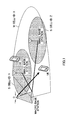
FIG. 1 is a conceptual diagram of a HetNet; -
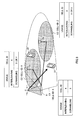
FIG. 2 is a diagram to show an example of interference coordination in a HetNet; -
FIG. 3 is a conceptual diagram of an interference reduction method according to the present embodiment; -
FIG. 4 is a diagram to show an example of an interference reduction method according to the present embodiment; -
FIG. 5 is a diagram to show another example of an interference reduction method according to the present embodiment; -
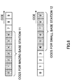
FIG. 6 is a diagram to show yet another example of an interference reduction method according to the present embodiment; -
FIG. 7 is a schematic diagram to show an example of a radio communication system according to the present embodiment; -
FIG. 8 is a diagram to explain an overall structure of a small base station according to the present embodiment; -
FIG. 9 is a diagram to explain an overall structure of a user terminal according to the present embodiment; -
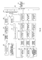
FIG. 10 is a functional configuration diagram to show a baseband processing section of a small base station according to the present embodiment, and part of higher layers; and -
FIG. 11 is a functional configuration diagram of a baseband processing section of a user terminal according to the present embodiment. -
FIG. 1 is a conceptual diagram of a HetNet. As shown inFIG. 1 , the HetNet includes a radio base station that forms a macro cell M (hereinafter referred to as a "macro base station"), radio base stations that form each small cell S (hereinafter referred to as "small base stations"), and user terminals (UE: User Equipment) that are connected to the macro base station or the small base stations. Note that the macro base station may be referred to as an "eNodeB (eNB)," a "macro eNB (MeNB)," a "transmission point" and so on. Also, the small base stations may be referred to as "pico eNBs," "femto eNBs," "transmission points" and so on. - The macro cell M is a cell having relatively wide coverage (for example, a radius of approximately 10 km), and may be referred to as a "wide area" and so on, and may be a sector. Also, the small cells S are cells having local coverage (for example, a radius of approximately several meters), and may be referred to as "local areas," "pico cells," "nano cells," "femto cells," "micro cells," "eLA (enhanced Local Area) cells" and so on.
- In the HetNet, as shown in
FIG. 1 , the macro base station and each small base station are arranged so that the macro cell M and each small cell S overlap geographically at least in part. Although the macro base station and each small base station are connected through, for example, a wired link such as an X2 interface, they may be connected through a radio link as well. - Also, in the HetNet, cell IDs to identify the macro cell M (macro base station) and the small cells S (small base stations), individually, are used. In
FIG. 1 , the macro cell M is identified by the cell ID "X," and the two small cells S are identified by "Y" or "Z," individually. - In a HetNet like this, an overlapping frequency regions are used between a macro cell M and small cells S. Consequently, a study is in progress to reduce interference (especially, interference between downlink signals) between the macro cell M and the small cells S by performing interference coordination (eICIC).
- Here, the downlink signals include downlink data signals (for example, a physical downlink shared channel (PDSCH) signal) in which user data and higher layer control information are transmitted, and downlink control signals (for example, a physical downlink control channel (PDCCH) signal, a physical hybrid-ARQ indicator channel (PHICH) signal, and a physical control format indicator channel (PCFICH) signal) in which control information is transmitted.
- For interference coordination between downlink data signals, it may be possible to prevent the use of overlapping radio resource regions between a macro cell M and a small cell S by using a time-domain approach and a frequency-domain approach.
- To be more specific, in the time-domain approach, in a time region (for example, a subframe) in which the PDSCH signal is allocated in either one of the macro cell M and the small cell S, a muting subframe is applied in the other cell. The muting subframe means a subframe where the PDSCH signal is not allocated, and is, for example, an almost blank subframe (ABS).
- Also, in the frequency-domain approach, as shown in
FIG. 2 , in a frequency region (for example, a physical resource block (PRB)) in which the PDSCH signal is allocated in either one of the macro cell M and the small cell S, the PDSCH signal is not allocated in the other cell. - Meanwhile, for interference coordination between downlink control signals, it may be possible to randomize interference by using different scrambling sequences and interleaving patterns between the macro cell M and the small cell S. Note that, as will be described later, the interleaving patterns may include shift patterns to be used in cyclic shifts, frequency offset values and so on.
- To be more specific, as shown in
FIG. 2 , the PDCCH signal in the macro cell M and the PDCCH signal in the small cell S are arranged in overlapping radio resource regions (maximum three OFDM symbols from the subframe top over the entire system band). In this case, scrambling is conducted using scrambling sequences that are each specific (cell-specific) to the macro cell M and the small cell S. Similarly, cyclic shifts are applied using cell-specific shift patterns. By this means, it is possible to randomize interference that is produced between the PDCCH signals of the macro cell M and the small cell S. - Here, the cell-specific scrambling sequences are, for example, determined based on
equation 1. Also, the cell-specific shift patterns are, for example, determined based onequation 2.

- In
equations 
is the cell ID, which varies per cell. Cell-specific scrambling sequences and shift patterns are generated based on this cell ID. By this means, different scrambling sequences and shift patterns are used between the macro cell M and the small cell S, so that interference between the PDCCHs of the macro cell M and the small cell S can be randomized (equalized). - Similarly, as for other downlink control signals such as the PCFICH signal and the PHICH signal, interference can be randomized (equalized) using cell-specific scrambling sequences and interleaving patterns (including frequency offset values and so on).
- As described above, interference between downlink control signals in the macro cell M and the small cell S is randomized (equalized) using cell-specific scrambling sequences and interleaving patterns (including shift patterns and frequency offset values). However, there is a threat that interference between downlink control signals in the macro cell M and the small cell S cannot be reduced sufficiently by interference randomization. So, the present inventors have studied an interference reduction method that can reduce interference between downlink control signals in the macro cell M and the small cell S more reliably, and arrived at the present invention.
- With the interference reduction method according to the present invention, the small base station transmits macro cell identification information to identify the macro cell M, to a user terminal in the small cell S. Also, the small base station allocates downlink control signals for the user terminal to radio resource units having different index numbers from those of radio resource units, to which downlink control signals transmitted from the macro base station are allocated. Also, the small base station interleaves the downlink control signals for the user terminal using interleaving patterns that are generated based on macro cell identification information, and that are the same as the interleaving patterns used in the macro base station.
- Here, the macro cell identification information is identification information of the macro cell M, and is, for example, the cell ID (also referred to as a "physical cell ID (PCI)") of the macro cell M. Also, small cell identification information (to be described later) is identification information of the small cell S, and is, for example, the cell ID (also referred to as a "PCI") of the small cell S. Note that, as long as the macro cell identification information and the small cell identification information are information specific to each cell, which includes the macro cell M and the small cell S, these are not limited to cell IDs.
- Also, although downlink control signals include the physical downlink control channel (PDCCH) signal, which transmits downlink control information (DCI), the physical control format indicator channel (PCFICH) signal, which transmits control format indicators (CFIs), or the physical hybrid ARQ indicator channel (PHICH) signal, which transmits delivery acknowledgment information (ACK/NACK/DTX) of the physical uplink shared data channel (PUSCH) signal, these are by no means limiting. For example, the downlink control signals may include the enhanced physical downlink control channel (enhanced PDCCH, ePDCCH, E-PDCCH) signal, which is frequency-division-multiplexed with the physical downlink shared data channel (PDSCH) signal and transmits DCI.
- Note that the radio resource units, to which DCI to be transmitted by the PDCCH is allocated, are control channel elements (CCEs). Also, the radio resource units, to which DCI to be transmitted by the enhanced PDCCH is allocated, are enhanced control channel elements (eCCEs). Also, the radio resource units, to which CFIs to be transmitted by the PCFICH and delivery acknowledgment information to be transmitted by the PHICH are allocated, are resource element groups (REGs). Note that an REG is formed with four resource elements (REs), and a CCE is formed with nine REGs. eCCEs may be formed with a plurality of enhanced resource element groups (eREGs), or may be formed by dividing a physical resource block (PRB) pair using at least one of frequency division, code division and time division.
- Also, interleaving means changing the order of resources in accordance with predetermined patterns, and here, means moving the resources where downlink control signals are allocated, at least in the frequency direction, and may include cyclic shifts and frequency offsets. Also, here, the interleaving patterns means patterns of moving the resources where downlink control signals are allocated, in the frequency direction, and may include shift patterns to be used for cyclic shifts and offset values to be used for frequency offsets.
- Now, an interference reduction method according to the present embodiment will be described. Although an example to use the PDCCH signal will be described below, this is by no means limiting. The interference reduction method is applicable to cases where downlink control signals are the PCFICH signal, the PHICH signal, the enhanced PDCCH signal and so on, by changing radio resource units to allocate the downlink control signals to, from CCEs to REGs and eCCEs. Also, assume that the following interference reduction method is applied to the radio communication system shown in
FIG. 7 . -
FIG. 3 is a conceptual diagram to show an interference reduction method according to the present embodiment. InFIG. 3 , amacro base station 11 transmits the cell ID "X" of a macro cell C1 to auser terminal 21 that connects to themacro base station 11. Themacro base station 11 generates an interleaving pattern (including a shift pattern) that is specific to the macro cell C1 using, for example, aboveequation 2, based on the cell ID "X." Themacro base station 11 interleaves (which includes applying a cyclic shift) the PDCCH signal for auser terminal 22 using the generated interleaving pattern and transmits the signal. - Meanwhile, in
FIG. 3 , asmall base station 12a transmits the cell ID "X" of the macro cell C1 to theuser terminal 22 that connects to thesmall base station 12a. Thesmall base station 12a generates the same interleaving pattern (including the shift pattern) as the interleaving pattern to be used in themacro base station 11, using, for example, aboveequation 2, based on the cell ID "X" of the macro cell C1. Thesmall base station 12 interleaves (which includes applying a cyclic shift) the PDCCH signal for theuser terminal 22 using the generated interleaving patterns and transmits the signal. - Here, the
small base station 12a may transmit the cell ID "X" of the macro cell C1, which is different from the subject cell(the small cell), using higher layer signaling such as RRC signaling, or may transmit the cell ID "X" using broadcast information such as MIBs (Master Information Blocks) or SIBs (System Information Blocks), to theuser terminal 22. Note that the cell ID "X" of the macro cell C1 may be stored in thesmall base station 12a in advance, or may be reported from themacro base station 11 to thesmall base station 12a. - Also, in
FIG. 3 , the PDCCH signal for theuser terminal 22 may be scrambled using either the same scrambling sequence as the scrambling sequence used in themacro base station 11 or a scrambling sequence that is specific to the small cell C2. The same scrambling sequence as the scrambling sequence used in themacro base station 11 is generated using, for example, aboveequation 1, based on the cell ID "X" of the macro cell C1. Meanwhile, the scrambling sequence that is specific to the small cell C2 is generated using, for example, aboveequation 1, based on the cell ID "Y" of the small cell C2. - An example of an interference reduction method according to the present embodiment will be described in detail with reference to
FIG. 4. FIG. 4 is a diagram to show an example of an interference reduction method according to the present embodiment. Note that thesmall base station 12 ofFIG. 4 may include thesmall base stations FIG. 3 . - As shown in
FIG. 4 , thesmall base station 12 allocates the PDCCH signal for theuser terminal 22 to CCEs having different index numbers from those of the PDCCH signal transmitted from themacro base station 11. Index number information that represents the index numbers of the CCEs used in themacro base station 11 is reported from themacro base station 11 to thesmall base station 12. Thesmall base station 12 allocates the PDCCH signal to CCEs having different index numbers from those of themacro base station 11. - For example, in
FIG. 4 , themacro base station 11 allocates the PDCCH signal for theuser terminal 21 to the CCEs having the index numbers "1," "4" and "5." Meanwhile, thesmall base station 12 allocates the PDCCH signal for theuser terminal 22 to the CCEs having the index numbers "0," "2," "8" and "9," which are different from those of themacro base station 11. - Also, in
FIG. 4 , thesmall base station 12 generates an interleaving pattern using, for example, aboveequation 2, based on the cell ID "X" of the macro cell C1. This interleaving pattern is generated based on the cell ID "X" of the macro cell C1, so that this interleaving pattern is the same as the interleaving pattern that is used in themacro base station 11. - Using this interleaving pattern, the
small base station 12 interleaves the PDCCH signal, to which CCEs having different index numbers from those of themacro base station 11 are allocated. With this interleaving, as shown inFIG. 4 , the PDCCH signal of thesmall base station 12 is mapped to different radio resources (for example, resource elements) from those of the PDCCH signal in themacro base station 11. - In this way, in
FIG. 4 , thesmall base station 12 allocates the PDCCH signal to CCEs having different index numbers from those of themacro base station 11, and interleaves the PDCCH signal using the same interleaving pattern as that of themacro base station 11. Consequently, since the radio resources (for example, resource elements) where the PDCCH signal is placed can be made different between themacro base station 11 and thesmall base station 12, it is possible to realize orthogonalization. Also, it is possible to carry out interference coordination between the PDCCH signals of the small base station and themacro base station 11 on the level of CCEs. - Note that, in the case shown in
FIG. 4 , thesmall base station 12 may scramble the PDCCH signal for theuser terminal 22 using either the same scrambling sequence as in themacro base station 11 or a scrambling sequence that is specific to the subject station (the small base station). - Another example of an interference reduction method according to the present invention will be described with reference to
FIG. 5. FIG. 5 is a diagram to show another example of an interference reduction method according to the present embodiment. - In
FIG. 4 , thesmall base station 12 allocates the PDCCH signal for theuser terminal 22 only to CCEs having different index numbers from those of themacro base station 11. Meanwhile, as shown inFIG. 5 , thesmall base station 12 may allocate the PDCCH signal for theuser terminal 22 not only to CCEs having different index numbers from those of themacro base station 11, but also to the CCEs having the same index numbers as those of themacro base station 11. - For example, in
FIG. 5 , themacro base station 11 allocates the PDCCH signal for theuser terminal 21 to the CCE having the index number "6." Also, thesmall base station 12 allocates the PDCCH signal for theuser terminal 22 to the CCE having the index number "6," which is the same index number as that of the CCE, to which the PDCCH signal from themacro base station 11 is allocated. - Also, the
small base station 12 interleaves the PDCCH signal, to which the CCE having the index number "6" is allocated, using the same interleaving pattern as the interleaving pattern that is used in themacro base station 11. By this means, as shown inFIG. 5 , the PDCCH signal is allocated to the same CCE , in themacro base station 11 and in thesmall base station 12, and mapped to the same radio resources (for example, resource elements). - So, the
small base station 12 scrambles the PDCCH signal for theuser terminal 22 using a scrambling sequence that is generated based on the cell ID of the subject cell and that is specific to the subject cell. By this means, the PDCCH signals in themacro base station 11 and thesmall base station 12 are scrambled using different scrambling sequences. As a result of this, even if the PDCCH signals of themacro base station 11 and thesmall base station 12 cannot be orthogonalized, it is still possible to randomize interference. - Yet another example of an interference reduction method according to the present embodiment will be described with reference to
FIG. 6. FIG. 6 is a diagram to show yet another example of an interference reduction method according to the present embodiment. - In
FIG. 4 andFIG. 5 , thesmall base station 12 allocates the PDCCH to CCEs having different index numbers from those of themacro base station 11, based on index number information reported from themacro base station 11. Meanwhile, as shown inFIG. 6 , the CCEs to which the PDCCH can be allocated in thesmall base station 12 and the CCEs to which the PDCCH can be allocated in themacro base station 11 may be determined in advance so that at least part of the index numbers are different. - In
FIG. 6 , the CCEs of the index numbers "0" to "6" are determined as CCEs for themacro base station 11. Meanwhile, the CCEs of the index numbers "4" to "9" are determined as CCEs for thesmall base station 12. Note that inFIG. 6 , although the CCEs of the index numbers "4" to "6" are determined for themacro base station 11 and thesmall base station 12 in an overlapping manner, CCEs that are determined in an overlapping manner may not exist as well. - In this way, by determining CCEs that can be used in both the
macro base station 11 and thesmall base station 12 in advance, it is possible to reduce the amount of signaling between themacro base station 11 and thesmall base station 12. - Now, a configuration of a radio communication system according to the present embodiment will be described.
-
FIG. 7 is a schematic configuration diagram of a radio communication system according to the present embodiment. Note that the radio communication system shown inFIG. 7 is a system to accommodate, for example, the LTE system or its successor system. In this radio communication system, carrier aggregation to group a plurality of fundamental frequency blocks into one, where the system band of the LTE system is one unit, is used. Also, this radio communication system may be referred to as "IMT-Advanced" or may be referred to as "4G." - As shown in
FIG. 7 , aradio communication system 1 has aradio base station 11 forming a macro cell C1 andradio base stations FIG. 7 , each small cell C2 is formed so that the small cell C2 overlaps with the macro cell C1 at least in part. Theradio base station 11 and theradio base stations 12 communicate withuser terminals 20 using frequency bands that at least partly overlap. - With the present embodiment, the
radio base station 11 and the small base stations 12 (including 12a and 12b) will be referred to as a "macro base station 11" and "small base stations 12," respectively. Note that themacro base station 11 may be referred to as an "eNodeB," a "radio base station apparatus," a "transmission point" and so on. Also thesmall base stations 12 may be referred to as "pico base stations," "femto base stations," "Home eNodeBs," "RRHs (Remote Radio Heads)," "micro base stations," "transmission points," and so on. - Also, the
user terminals 20 are terminals supporting each communication scheme such as LTE and LTE-A, and may be not only mobile communication terminals but may also be fixed communication terminals as well. With the present embodiment, althoughuser terminals 20 may be referred to as "user terminals 21" when connected to themacro base station 11 and may be referred to as "user terminals 22" when connected to thesmall base stations 12, both have the same configurations. - As shown in
FIG. 7 , themacro base station 11 and eachsmall base station 12 are each connected to ahigher station apparatus 30, and connected to acore network 40 via thehigher station apparatus 30. Note that thehigher station apparatus 30 may be, for example, an access gateway apparatus, a radio network controller (RNC), a mobility management entity (MME) and so on, but is by no means limited to these. Also, eachsmall base station 12 may be connected with the higher station apparatus via themacro base station 11. - Also, the
macro base station 11 and eachsmall base station 12 are connected using, for example, an X2 interface. Although an example in which themacro base station 11 and eachsmall base station 12 are connected using wire connection such as optical fiber will be described below, they may be connected using wireless connection. - In the
radio communication system 1, as radio access schemes, OFDMA (Orthogonal Frequency Division Multiple Access) is applied to the downlink, and SC-FDMA (Single-Carrier Frequency-Division Multiple Access) is applied to the uplink. OFDMA is a multi-carrier transmission scheme to perform communication by dividing a frequency band into a plurality of narrow frequency bands (subcarriers) and mapping data to each subcarrier. SC-FDMA is a single carrier transmission scheme to reduce interference between terminals by dividing, per terminal, the system band into bands formed with one or continuous resource blocks, and allowing a plurality of terminals to use mutually different bands. - Signals to be used in the radio communication system shown in
FIG. 7 will be described. Downlink signals include downlink data signals and downlink control signals. The downlink data signals include, for example, the PDSCH signal that transmits user data and higher layer control information. Also, the downlink control signals include, for example, the PDCCH signal, which transmits downlink control information (DCI), the PCFICH signal, which transmits control format indicators (CFIs), the PHICH signal, which transmits delivery acknowledgment information (ACK/NACK/DTX), and the enhanced PDCCH signal, which transmits downlink control information (DCI) and which is frequency-division-multiplexed with the PDSCH signal. - Similarly, uplink signals include uplink data signals and uplink control signals. The uplink data signals include, for example, the PUSCH (Physical Uplink Shared CHannel) signal to transmit user data and uplink layer control information. Also, the uplink control signals include, for example, the PUCCH (Physical Uplink Control CHannel) signal, which transmits downlink channel state information (CSI) and delivery acknowledgment information (ACK/NACK/DTX), and so on.
-
FIG. 8 is a diagram of an overall structure of thesmall base station 12 according to the present embodiment. Thesmall base station 12 includes a plurality of transmitting/receivingantennas 101 for MIMO transmission, amplifyingsections 102, transmitting/receiving sections 103 (transmitting sections), a basebandsignal processing section 104, acall processing section 105 and atransmission path interface 106. - Downlink data signals are input from the
higher station apparatus 30 into the basebandsignal processing section 104, via thetransmission path interface 106. - In the baseband
signal processing section 104, a PDCP layer process, division and coupling of user data, RLC (Radio Link Control) layer transmission processes such as an RLC retransmission control transmission process, MAC (Medium Access Control) retransmission control, including, for example, an HARQ transmission process, scheduling, transport format selection, channel coding, an inverse fast Fourier transform (IFFT) process, and a precoding process are performed, and the result is transferred to each transmitting/receivingsection 103. Also, the downlink control channel signals are also subjected to transmission processes such as channel coding and an inverse fast Fourier transform, and are transferred to each transmitting/receivingsection 103. - Also, the baseband
signal processing section 104 reports, to theuser terminals 20, broadcast information for allowing communication in the cell, through a broadcast channel. This broadcast information includes, for example, the cell ID of the subject cell, and system bandwidth on the uplink or the downlink and so on. - Each transmitting/receiving
section 103 converts baseband signals, which are precoded and output from the basebandsignal processing section 104 on a per antenna basis, into a radio frequency band. The amplifyingsections 102 amplify the radio frequency signals having been subjected to frequency conversion, and output the results through the transmitting/receivingantennas 101. - Meanwhile, as for the uplink signals, the radio frequency signals that are received in each transmitting/receiving
antennas 101 are amplified in the amplifyingsections 102, converted into baseband signals through frequency conversion in each transmitting/receivingsection 103, and input in the basebandsignal processing section 104. - In the baseband
signal processing section 104, the uplink signals included in the input baseband signals are subjected to an FFT process, an IDFT process, error correction decoding, a MAC retransmission control receiving process, and RLC layer and PDCP layer receiving processes, and the result is transferred to thehigher station apparatus 30 via thetransmission path interface 106. Thecall processing section 105 performs call processing such as setting up and releasing communication channels, manages the state of thesmall base station 12 and manages the radio resources. - Also, control information reported from the
macro base station 11 to thesmall base station 12 is input in the basebandsignal processing section 104 via thetransmission path interface 106. The control information reported from themacro base station 11 includes, for example, the cell ID of the macro cell C1 and index number information (to be described later). -
FIG. 9 is a diagram of an overall structure of theuser terminal 20 according to the present embodiment. Theuser terminal 20 has a plurality of transmitting/receivingantennas 201 for MIMO transmission, amplifyingsections 202, transmitting/receiving sections (receiving sections) 203, a basebandsignal processing section 204, and anapplication section 205. - As for the downlink data signals, radio frequency signals that are received in the plurality of transmitting/receiving
antennas 201 are each amplified in the amplifyingsections 202, and subjected to frequency conversion and converted into baseband signals in the transmitting/receivingsections 203. These baseband signals are subjected to an FFT process, error correction decoding, retransmission control receiving process and so on in the basebandsignal processing section 204. The user data included in these downlink data signals is transferred to theapplication section 205. Theapplication section 205 performs processes related to higher layers above the physical layer and the MAC layer, and so on. Also, the broadcast information included in the downlink data signals is transferred to theapplication section 205. - Meanwhile, the uplink data signals are input from the
application section 205 to the basebandsignal processing section 204. The basebandsignal processing section 204 performs a retransmission control (H-ARQ (Hybrid ARQ)) transmission process, channel coding, precoding, a DFT process, an IFFT process and so on, and the result is transferred to each transmitting/receivingsection 203. The transmitting/receivingsections 203 convert the baseband signals that are output from the basebandsignal processing section 204 into a radio frequency band. After that, the amplifyingsections 202 amplify the radio frequency signals having been subjected to frequency conversion, and transmit the result from the transmitting/receivingantennas 201. -
FIG. 10 is a functional configuration diagram of the basebandsignal processing section 104 provided in thesmall base station 12 according to the present embodiment, and part of higher layers. Note that, althoughFIG. 10 primarily shows downlink (transmitting) functional configurations, thesmall base station 12 may have uplink (receiving) functional configurations as well. - As shown in
FIG. 10 , thesmall base station 12 has a higher layer controlinformation generating section 300, adata generating section 301, achannel coding section 302, amodulation section 303, amapping section 304, a downlink control information (DCI)generating section 305, a control format indicator (CFI)generating section 306, a delivery acknowledgmentinformation generating section 307,channel coding sections 308, scramblingsections 309,modulation sections 310, interleavingsections 311, anIFFT section 312, amapping section 313, aweight multiplication section 314, aCP inserting section 315 and ascheduling section 316. - The higher layer control
information generating section 300 generates higher layer control information on a peruser terminal 20 basis. Also, the higher layer control information is control information that is sent by higher layer signaling (for example, RRC signaling), and includes, for example, the cell ID of the macro cell C1 reported from themacro base station 11. Thedata generating section 301 generates downlink user data peruser terminal 20. - The downlink user data that is generated in the
data generating section 301 and the higher layer control information that is generated in the higher layer controlinformation generating section 300 are input in thechannel coding section 302 as the PDSCH signal. Thechannel coding section 302 performs channel coding of the PDSCH signal for eachuser terminal 20 in accordance with the coding rate determined based on feedback information from eachuser terminal 20. Themodulation section 303 modulates the PDSCH signal having been subjected to channel coding, in accordance with the modulation scheme determined based on feedback information from eachuser terminal 20. Themapping section 304 maps the modulated PDSCH signal to radio resources (for example, resource elements) in accordance with commands from thescheduling section 316. - The
DCI generating section 305 generates downlink control information (DCI) based on the scheduling information from thescheduling section 316. The DCI includes cell-specific shared control information and UE-specific control information. The UE-specific control information includes PDSCH allocation information (DL assignment), PUSCH allocation information (UL grants) and so on. - Also, the
DCI generating section 305 can generate DCI to be transmitted by the PDCCH on a per control channel element (CCE) basis and DCI to be transmitted by the enhanced PDCCH on a per enhanced control channel element (eCCE) basis. Also, the sizes of CCEs and eCCEs (the number of REs) may be different or may be the same. - Also, as shown in
FIG. 4 , theDCI generating section 305 allocates the generated DCI to CCEs having different index numbers from those of themacro base station 11. Furthermore, as shown inFIG. 5 , theDCI generating section 305 may allocate the DCI to CCEs having the same index numbers as in themacro base station 11. The DCI allocated to CCEs is input in thechannel coding sections 308 as the PDCCH signal. Similarly, the DCI to be transmitted by the enhanced PDCCH is allocated to eCCEs, and input in thechannel coding sections 308 as the enhanced PDCCH signal. TheDCI generating section 305 constitutes the allocation section of the present invention. - Note that the index numbers of the CCEs (index number information) used in the
macro base station 11 may be reported from themacro base station 11 to theDCI generating section 305. Alternatively, CCEs that can be used in thesmall base station 12 and CCEs that can be used in themacro base station 11 may be determined in advance so that at least part of the index numbers are different. In the latter case, it is possible to reduce the amount of control that is required between themacro base station 11 and thesmall base station 12. Also, the same will apply to the index numbers of eCCEs. - The
CFI generating section 306 generates control format indicators (CFIs) to be transmitted by the PCFICH based on scheduling information from thescheduling section 316. TheCFI generating section 306 can generate CFIs on a per resource element group (REG) basis. - Also, the
CFI generating section 306 allocates the CFIs to REGs having different index numbers from those of themacro base station 11. Also, theCFI generating section 306 may allocate the CFIs to REGs having the same index numbers as in themacro base station 11. The CFIs that are allocated to the REGs are input in thechannel coding sections 308. TheCFI generating section 306 constitutes the allocation section of the present invention. - The delivery acknowledgment
information generating section 307 generates delivery acknowledgment information (ACK/NACK/DTX) to be transmitted by the PHICH based on the scheduling information from thescheduling section 316. The delivery acknowledgmentinformation generating section 307 can generate delivery acknowledgment information on a per resource element group (REG) basis. - Also, the delivery acknowledgment
information generating section 307 allocates delivery acknowledgment information to REGs having different index numbers from those of themacro base station 11. Also, the delivery acknowledgmentinformation generating section 307 may allocate delivery acknowledgment information to REGs having the same index numbers as in themacro base station 11. The delivery acknowledgment information allocated to the REGs is input in thechannel coding sections 308 as the PHICH signal. The delivery acknowledgmentinformation generating section 307 constitutes the allocation section of the present invention. - Note that the index numbers (index number information) of the REGs used in the
macro base station 11 may be reported from themacro base station 11 to theCFI generating section 306 and the delivery acknowledgmentinformation generating section 307, or may be determined in advance. - The
channel coding sections 308 perform channel coding of the input downlink signals in a predetermined coding rate. To be more specific, thechannel coding sections 308 perform channel coding of the PDCCH signal input from theDCI generating section 305, the enhanced PDCCH signal input from theCFI generating section 306, the PCFICH signal input from theCFI generating section 306, and the PHICH signal input from the delivery acknowledgmentinformation generating section 307. - The scrambling
sections 309 perform channel coding of the downlink control signals having been subjected to channel coding using predetermined scrambling sequences. To be more specific, the scramblingsections 309 scrambles the PDCCH signal, the enhanced PDCCH signal, the PCFICH signal, and the PHICH signal, that have been subjected to channel coding, using the same scrambling sequence as that used in themacro base station 11 or using a scrambling sequence that is specific to the subject cell. - Here, the same scrambling sequence as the scrambling sequence used in the
macro base station 11 is generated based on the cell ID of the macro cell C1 (macro cell identification information). Meanwhile, the scrambling sequence that is specific to the subject cell is generated based on the cell ID (small cell identification information) of the subject cell (small cell C2). - When a scrambling sequence that is specific to the subject cell is used, it is possible to randomize interference between downlink control signals in the
macro base station 11 and thesmall base station 12. Consequently, this method is effective when CCEs having the same index numbers as in themacro base station 11 are allocated to the PDCCH signal. Similarly, this method is effective when REGs having the same index numbers as in themacro base station 11 are allocated to the PCFICH signal and the PHICH signal. Also, this method is also effective when eCCEs having the same index numbers as in themacro base station 11 are allocated to the enhanced PDCCH signal. - The
modulation sections 310 modulate the scrambled downlink control signals in a predetermined modulation scheme. To be more specific, themodulation sections 310 modulate the scrambled PDCCH signal, the enhanced PDCCH signal, the PCFICH signal, which have been scrambled, and the PHICH signal. Note that themodulation sections 310 output the PDCCH signal, the PCFICH signal and the PHICH signal that have been modulated, to theinterleaving sections 311. Meanwhile, themodulation sections 310 output the modulated enhanced PDCCH signal to themapping section 313. - The interleaving
sections 311 interleave the modulated downlink control signals using the same interleaving pattern as the interleaving pattern that is used in themacro base station 11. The interleaving pattern is generated based on the cell ID of the macro cell C1 (macro cell identification information). - Note that, as described above, the interleaving pattern may be a shift pattern of a cyclic shift and an offset value of a frequency offset. Consequently, the interleaving
sections 311 can apply a cyclic shift to the modulated PDCCH signal using the same shift pattern as the shift pattern that is used in themacro base station 11. Also, the interleavingsections 311 can move the PCFICH signal and the PHICH signal, which have been modulated, in the frequency direction using the same offset values as the frequency offset values used in themacro base station 11. - In the
DCI generating section 305, when the PDCCH signal is allocated to CCEs having different index numbers from those of themacro base station 11, by the interleavingsections 311, this PDCCH signal is mapped to different radio resources (for example, resource elements) from those of the PDCCH signal in themacro base station 11. In this case, the PDCCH signals in themacro base station 11 and thesmall base station 12 are orthogonalized, so that interference is reduced. - Similarly, in the
CFI generating section 306 and the delivery acknowledgmentinformation generating section 307, when the PCFICH signal and the PHICH signal are allocated to REGs having different index numbers from those of themacro base station 11, by the interleavingsections 311, these PCFICH signals and PHICH signals are mapped to different radio resources (for example, resource elements) from those of themacro base station 11. In this case, the PCFICH signals and the PHICH signals in themacro base station 11 and thesmall base station 12 are orthogonalized, so that interference is reduced. - Meanwhile, in the
DCI generating section 305, when the PDCCH signal is allocated to CCEs having the same index numbers as in themacro base station 11, by the interleavingsections 311, this PDCCH signal is mapped to the same radio resources as the PDCCH signal in themacro base station 11. In this case, it is preferable to randomize interference by scrambling the PDCCH signal using a cell-specific scrambling sequence in the scramblingsections 309. - Similarly, in the
CFI generating section 306 and the delivery acknowledgmentinformation generating section 307, when the PCFICH signal and the PHICH signal are allocated to REGs having the same index numbers as in themacro base station 11, by the interleavingsections 311, these PCFICH signal and PHICH signal are mapped to the same radio resources (for example, resource elements) as in themacro base station 11. In this case, it is preferable to randomize interference by scrambling the PCFICH signal and the PHICH signal using cell-specific scrambling sequences in the scramblingsections 309. - The
mapping section 313 maps the enhanced PDCCH signal to the predetermined radio resources (for example, resource elements). At this time, themapping section 313 can interleave the enhanced PDCCH signal using the same interleaving pattern as the interleaving pattern that is used in themacro base station 11, based on the cell ID of the macro cell C1 (macro cell identification information). By this means, it is possible to allocate the enhanced PDCCH signal to different radio resources from those in themacro base station 11. - The enhanced PDCCH signal mapped in the
mapping section 313 is input in theweight multiplication section 314 with the PDSCH signal mapped in themapping section 304. Theweight multiplication section 314 multiplies the PDSCH signal, the enhanced PDCCH signal, and the demodulated reference signal by user terminal 20-specific precoding weights, and pre-encodes them. - The
IFFT section 312 performs an inverse fast Fourier transform process on the input signals from the interleavingsections 311 and theweight multiplication section 314, and converts the frequency domain signals into time domain signals. Cyclic prefixes (CPs) to function as guard intervals are inserted in the output signals from theIFFT section 312 by theCP inserting section 315, and the signals are output to the transmitting/receivingsections 103. - The
scheduling section 316 schedules the PDSCH signal and the enhanced PDCCH signal and generates scheduling information. Thescheduling section 316 outputs the generated scheduling information to theDCI generating section 305, theCFI generating section 306, and the delivery acknowledgmentinformation generating section 307. -
FIG. 11 is a functional configuration diagram of the basebandsignal processing section 104 provided in theuser terminal 20. Note that, althoughFIG. 11 primarily shows downlink (receiving) functional configurations, theuser terminal 20 may have uplink (transmitting) functional configurations as well. Also, although a case in which theuser terminal 20 is connected to thesmall base station 12 will be mainly described below, theuser terminal 20 may be connected to themacro base station 11 as well. - The
user terminal 20 has aCP removing section 401, anFFT section 402, ademapping section 403, adeinterleaving section 404, aPCFICH demodulation section 405, aPDCCH demodulation section 406, aPHICH demodulation section 407, an enhancedPDCCH demodulation section 408, aPDSCH demodulation section 409, and achannel estimation section 410. - Downlink signals received from the
small base station 12 have the cyclic prefixes (CPs) removed in theCP removing section 401. The downlink signals, from which the CPs have been removed, are input in theFFT section 402. TheFFT section 402 performs a fast Fourier transform (FFT) on the downlink signals, converts the time domain signals into frequency domain signals, and inputs these signals in thedemapping section 403. Thedemapping section 403 demaps the downlink signals. Note that the demapping process by thedemapping section 403 is performed based on higher layer control information that is received as input from theapplication section 205. - The
deinterleaving section 404 deinterleaved the demapped downlink control signals using the same interleaving pattern as the interleaving pattern that is used in themacro base station 11. This interleaving pattern is generated based on the cell ID of the macro cell C1 (macro cell identification information) reported from thesmall base station 12. Note that the cell ID of the macro cell C1 may be reported by either higher layer signaling or the broadcast signal from thesmall base station 12. - Also, the
deinterleaving section 404 outputs the PCFICH signal, the PDCCH signal and the PHICH signal that have been deinterleaved, to thePCFICH demodulation section 405, thePDCCH demodulation section 406, and thePHICH demodulation section 407, respectively. - The
PCFICH demodulation section 405 performs demodulation, descrambling and channel decoding of the PCFICH signal output from thedeinterleaving section 404. To be more specific, thePCFICH demodulation section 405 descrambles the PCFICH signal using the same scrambling sequence as in themacro base station 11 or using a scrambling sequence that is specific to the subject cell. - The
PDCCH demodulation section 406 performs blind decoding, demodulation, descrambling and channel decoding of the PDCCH signal output from thedeinterleaving section 404, based on the channel estimation result in thechannel estimation section 410. To be more specific, thePDCCH demodulation section 406 descrambles the PDCCH signal using the same scrambling sequence as in themacro base station 11 or using a scrambling sequence that is specific to the subject cell. - The
PHICH demodulation section 407 performs demodulation, descrambling and channel decoding of the PHICH signal output from thedeinterleaving section 404. To be more specific, thePHICH demodulation section 407 descrambles the PHICH signal using the same scrambling sequence as in themacro base station 11 or using a scrambling sequence that is specific to the subject cell. - The enhanced
PDCCH demodulation section 408 performs deinterleaving, blind decoding, demodulation, descrambling and channel decoding of the enhanced PDCCH signal, based on the channel estimation result in thechannel estimation section 410. To be more specific, the enhancedPDCCH demodulation section 408 deinterleaves the demapped enhanced PDCCH signal using the same interleaving pattern as the interleaving pattern that is used in themacro base station 11. Also, the enhancedPDCCH demodulation section 408 descrambles the PDCCH signal using the same scrambling sequence as in themacro base station 11 or using a scrambling sequence that is specific to the subject cell. - Here, in the
PCFICH demodulation section 405, thePDCCH demodulation section 406, thePHICH demodulation section 407 and the enhancedPDCCH demodulation section 408, the same scrambling sequences as in themacro base station 11 are generated based on the cell ID of the macro cell C1 (macro cell identification information). Also, the scrambling sequences that are specific to the subject cell are generated based on the cell ID of the subject cell (small cell C2) (small cell identification information). - The
PDSCH demodulation section 409 performs demodulation and channel decoding of the PDSCH signal and so on output from thedemapping section 403, based on the channel estimation result in thechannel estimation section 410. To be more specific, thePDSCH demodulation section 409 demodulates the PDSCH signal allocated to the subject terminal based on DCI demodulated in thePDCCH demodulation section 406 or the enhancedPDCCH demodulation section 408, and acquires downlink data (downlink user data and higher layer control information) for the subject terminal. - The
channel estimation section 410 performs channel estimation using demodulation reference signals (DM-RSs), measurement reference signals (CRSs and CSI-RSs) and so on. Thechannel estimation section 410 outputs the result of channel estimation by the measurement reference signals (CRSs and CSI-RSs) to thePDCCH demodulation section 406. Meanwhile, thechannel estimation section 410 outputs the result of channel estimation by the demodulation reference signals (DM-RSs) to thePDSCH demodulation section 409. - As has been described above, with the
radio communication system 1 according to the present embodiment, thesmall base station 12 allocates downlink control signals to radio resource units (for example, CCEs) having different index numbers from those in themacro base station 11, and interleaves the downlink control signals using the same interleaving patterns as in themacro base station 11. Consequently, the radio resources (for example, resource elements) where downlink control signals are allocated can be made different between themacro base station 11 and thesmall base station 12, so that it is possible to realize orthogonalization. Also, it is possible to perform interference coordination between the downlink control signals of the small base station and themacro base station 11 on the level of radio resource allocation units (for example, on the level of CCEs ). - Now, although the present invention has been described in detail with reference to the above embodiment, it should be obvious to a person skilled in the art that the present invention is by no means limited to the embodiment described herein. The present invention can be implemented with various corrections and in various modifications, without departing from the spirit and scope of the present invention defined by the recitations of the claims. Consequently, the descriptions herein are provided only for the purpose of explaining examples, and should by no means be construed to limit the present invention in any way.
- The disclosure of Japanese Patent Application No.
2012-175148, filed on August 7, 2012
Claims (10)
- An interference reduction method in a small base station that forms a small cell so that at least part of the small cell overlaps with a macro cell that is formed by a macro base station, the interference reduction method comprising the steps of:transmitting macro cell identification information that identifies the macro cell, to a user terminal in the small cell;allocating a downlink control signal for the user terminal to a radio resource unit having a different index number from that of a radio resource unit where a downlink control signal to be transmitted from the macro base station is allocated; andinterleaving the downlink control signal for the user terminal using an interleaving pattern that is generated based on the macro cell identification information and that is same as an interleaving pattern used in the macro base station.
- The interference reduction method according to claim 1, wherein the downlink control signal for the user terminal is scrambled using a scrambling sequence that is generated based on the macro cell identification information and that is same as a scrambling sequence used in the macro base station.
- The interference reduction method according to claim 1 or claim 2, wherein:in the allocating step, the downlink control signal for the user terminal is allocated to a radio resource unit having a same index number as that of the radio resource unit where the downlink control signal to be transmitted from the macro base station is allocated; andthe downlink control signal for the user terminal is scrambled using a scrambling sequence that is generated based on small cell identification information that identifies the small cell, and that is specific to the small cell.
- The interference reduction method according to claim 1, wherein the index number of the radio resource unit where the downlink control signal to be transmitted from the macro base station is allocated is reported from the macro base station to the small base station.
- The interference reduction method according to claim 1, wherein, a radio resource unit where the downlink control signal can be allocated in the small base station and a radio resource unit where the downlink control signal can be allocated in the macro base station are determined in advance so that at least part of index numbers are different.
- The interference reduction method according to claim 1, wherein:the downlink control signal is a physical downlink control channel (PDCCH) signal that transmits downlink control information; andthe radio resource unit is a control channel element (CCE).
- The interference reduction method according to claim 1, wherein:the downlink control signal is a physical control format indicator channel (PCFICH) signal that transmits a control format indicator, or a physical hybrid ARQ indicator channel (PHICH) signal that transmits delivery acknowledgment information of a physical uplink shared data channel (PUSCH) signal; andthe radio resource units are resource element groups (REGs).
- A radio base station that forms a small cell so that at least part of the small cell overlaps with a macro cell that is formed by a macro base station, the radio base station comprising:a transmission section configured to transmit macro cell identification information that identifies the macro cell, to a user terminal in the small cell;an allocation section configured to allocate a downlink control signal for the user terminal to a radio resource unit having a different index number from that of a radio resource unit where a downlink control signal to be transmitted from the macro base station is allocated; andan interleaving section configured to interleave the downlink control signal for the user terminal using an interleaving pattern that is generated based on the macro cell identification information and that is same as an interleaving pattern used in the macro base station.
- A user terminal that receives downlink control information from a small base station that forms a small cell so that at least part of the small cell overlaps with a macro cell that is formed by a macro base station, the user terminal comprising:a receiving section configured to receive macro cell identification information that identifies the macro cell, from the small base station; anda deinterleaving section configured to deinterleave the downlink control signal using an interleaving pattern that is generated based on the macro cell identification information and that is same as an interleaving pattern used in the macro base station; andthe downlink control signal is allocated to a radio resource unit having a different index number from that of a radio resource unit where a downlink control signal to be transmitted from the macro base station is allocated.
- A radio communication system that includes a macro base station that forms a macro cell and a small base station that forms a small cell so that at least part of the small cell overlaps with the macro cell, wherein:the small base station comprises:a transmission section configured to transmit macro cell identification information that identifies the macro cell, to a user terminal in the small cell;an allocation section configured to allocate a downlink control signal for the user terminal to a radio resource unit having a different index number from that of a radio resource unit where a downlink control signal to be transmitted from the macro base station is allocated; andan interleaving section configured to interleave the downlink control signal for the user terminal using an interleaving pattern that is generated based on the macro cell identification information and that is same as an interleaving pattern used in the macro base station; andthe user terminal comprises:a deinterleaving section configured to deinterleave the downlink control signal using the interleaving pattern.
Applications Claiming Priority (2)
| Application Number | Priority Date | Filing Date | Title |
|---|---|---|---|
| JP2012175148A JP6033601B2 (en) | 2012-08-07 | 2012-08-07 | Interference reduction method, radio base station, user terminal, and radio communication system |
| PCT/JP2013/068655 WO2014024615A1 (en) | 2012-08-07 | 2013-07-08 | Interference reduction method, wireless base station, user terminal, and wireless communication system |
Publications (2)
| Publication Number | Publication Date |
|---|---|
| EP2884788A1 true EP2884788A1 (en) | 2015-06-17 |
| EP2884788A4 EP2884788A4 (en) | 2016-03-30 |
Family
ID=50067855
Family Applications (1)
| Application Number | Title | Priority Date | Filing Date |
|---|---|---|---|
| EP13828535.8A Withdrawn EP2884788A4 (en) | 2012-08-07 | 2013-07-08 | INTERFERENCE REDUCTION METHOD, WIRELESS BASE STATION, USER TERMINAL AND WIRELESS COMMUNICATION SYSTEM |
Country Status (4)
| Country | Link |
|---|---|
| US (1) | US9628197B2 (en) |
| EP (1) | EP2884788A4 (en) |
| JP (1) | JP6033601B2 (en) |
| WO (1) | WO2014024615A1 (en) |
Families Citing this family (5)
| Publication number | Priority date | Publication date | Assignee | Title |
|---|---|---|---|---|
| IL194996A0 (en) * | 2008-10-30 | 2011-08-01 | Mariana Goldhamer | A method for depoying heterogeneous base stations in a wireless network |
| CN107465483B (en) * | 2016-06-03 | 2020-11-27 | 华为技术有限公司 | License-free transmission method and device |
| CN116249213A (en) * | 2016-08-05 | 2023-06-09 | 三菱电机株式会社 | Communication system, first base station, second base station, and user equipment |
| CN112534787B (en) * | 2018-08-08 | 2022-05-27 | 中兴通讯股份有限公司 | Wireless communication method, wireless communication device and computer readable medium |
| US12317144B2 (en) * | 2020-06-15 | 2025-05-27 | Nippon Telegraph And Telephone Corporation | Radio communication system, control method and control device for radio communication system, and radio communication system control program |
Family Cites Families (7)
| Publication number | Priority date | Publication date | Assignee | Title |
|---|---|---|---|---|
| JP5089504B2 (en) * | 2008-07-01 | 2012-12-05 | 株式会社エヌ・ティ・ティ・ドコモ | Wireless communication system, base station, user apparatus and method |
| EP2326127B1 (en) * | 2009-11-18 | 2017-11-15 | Mitsubishi Electric R&D Centre Europe B.V. | Method and a device for controlling signals transferred by a wireless telecommunication device |
| KR101707870B1 (en) * | 2009-12-15 | 2017-02-17 | 엘지전자 주식회사 | Method and apparatus for removing inter-heterogeneous cell interference |
| KR101552280B1 (en) * | 2009-12-23 | 2015-09-11 | 삼성전자주식회사 | Method and apparatus for initial connection of terminal using power reduction request in heterogeneous network |
| JP5467146B2 (en) * | 2010-04-16 | 2014-04-09 | 京セラ株式会社 | Wireless communication system, high power base station, low power base station, and communication control method |
| JP5366890B2 (en) * | 2010-06-21 | 2013-12-11 | 株式会社エヌ・ティ・ティ・ドコモ | Base station apparatus, mobile terminal apparatus and communication control method |
| EP2439984B1 (en) * | 2010-10-05 | 2015-09-02 | Alcatel Lucent | Interference mitigation on a physical downlink control channel |
-
2012
- 2012-08-07 JP JP2012175148A patent/JP6033601B2/en not_active Expired - Fee Related
-
2013
- 2013-07-08 WO PCT/JP2013/068655 patent/WO2014024615A1/en not_active Ceased
- 2013-07-08 EP EP13828535.8A patent/EP2884788A4/en not_active Withdrawn
- 2013-07-08 US US14/419,533 patent/US9628197B2/en not_active Expired - Fee Related
Also Published As
| Publication number | Publication date |
|---|---|
| JP2014036263A (en) | 2014-02-24 |
| US9628197B2 (en) | 2017-04-18 |
| WO2014024615A1 (en) | 2014-02-13 |
| EP2884788A4 (en) | 2016-03-30 |
| US20150229413A1 (en) | 2015-08-13 |
| JP6033601B2 (en) | 2016-11-30 |
Similar Documents
| Publication | Publication Date | Title |
|---|---|---|
| EP2903371B1 (en) | Radio base station, user terminal, radio communication system, and radio communication method | |
| EP2876960B1 (en) | Collision prevention during transmissin of control information using ePDCCH resources. | |
| US9491749B2 (en) | Radio communication method, radio communication system and radio base station | |
| US9763240B2 (en) | Blind decoding method, radio base station, user terminal and radio communication system | |
| EP3780827B1 (en) | Radio base station, user terminal, radio communication system and radio communication method | |
| CN103503543B (en) | Radio base station apparatus, mobile terminal apparatus, wireless communications method and wireless communication system | |
| EP2811799A1 (en) | Wireless base station device, user terminal, wireless communication system, and wireless communication method | |
| US9882694B2 (en) | Radio base station, user terminal, radio communication system and radio communication method | |
| EP2908587A1 (en) | User terminal, wireless base station, wireless communication system, and wireless communication method | |
| JP6068860B2 (en) | Wireless communication method, wireless base station, user terminal, and wireless communication system | |
| EP3104634A1 (en) | User terminal, wireless base station, and wireless communication method | |
| EP2911463A1 (en) | Radio communication method, radio communication system, radio base station and user terminal | |
| US9628197B2 (en) | Interference reduction method, radio base station, user terminal and radio communication system |
Legal Events
| Date | Code | Title | Description |
|---|---|---|---|
| PUAI | Public reference made under article 153(3) epc to a published international application that has entered the european phase |
Free format text: ORIGINAL CODE: 0009012 |
|
| 17P | Request for examination filed |
Effective date: 20150220 |
|
| AK | Designated contracting states |
Kind code of ref document: A1 Designated state(s): AL AT BE BG CH CY CZ DE DK EE ES FI FR GB GR HR HU IE IS IT LI LT LU LV MC MK MT NL NO PL PT RO RS SE SI SK SM TR |
|
| AX | Request for extension of the european patent |
Extension state: BA ME |
|
| DAX | Request for extension of the european patent (deleted) | ||
| RA4 | Supplementary search report drawn up and despatched (corrected) |
Effective date: 20160225 |
|
| RIC1 | Information provided on ipc code assigned before grant |
Ipc: H04L 5/00 20060101AFI20160219BHEP |
|
| RAP1 | Party data changed (applicant data changed or rights of an application transferred) |
Owner name: NTT DOCOMO, INC. |
|
| 17Q | First examination report despatched |
Effective date: 20180607 |
|
| STAA | Information on the status of an ep patent application or granted ep patent |
Free format text: STATUS: THE APPLICATION HAS BEEN WITHDRAWN |
|
| 18W | Application withdrawn |
Effective date: 20181009 |