EP2884615A1 - Modular power electronics distribution system - Google Patents
Modular power electronics distribution system Download PDFInfo
- Publication number
- EP2884615A1 EP2884615A1 EP14196020.3A EP14196020A EP2884615A1 EP 2884615 A1 EP2884615 A1 EP 2884615A1 EP 14196020 A EP14196020 A EP 14196020A EP 2884615 A1 EP2884615 A1 EP 2884615A1
- Authority
- EP
- European Patent Office
- Prior art keywords
- power
- modules
- module
- controller
- load
- Prior art date
- Legal status (The legal status is an assumption and is not a legal conclusion. Google has not performed a legal analysis and makes no representation as to the accuracy of the status listed.)
- Granted
Links
Images


Classifications
-
- H—ELECTRICITY
- H02—GENERATION; CONVERSION OR DISTRIBUTION OF ELECTRIC POWER
- H02J—ELECTRIC POWER NETWORKS; CIRCUIT ARRANGEMENTS OR SYSTEMS FOR SUPPLYING OR DISTRIBUTING ELECTRIC POWER; SYSTEMS FOR STORING ELECTRIC ENERGY
- H02J3/00—Circuit arrangements for AC mains or AC distribution networks
- H02J3/38—Arrangements for feeding a single network from two or more generators or sources in parallel; Arrangements for feeding already energised networks from additional generators or sources in parallel
- H02J3/46—Controlling the sharing of generated power between the generators, sources or networks
-
- F—MECHANICAL ENGINEERING; LIGHTING; HEATING; WEAPONS; BLASTING
- F02—COMBUSTION ENGINES; HOT-GAS OR COMBUSTION-PRODUCT ENGINE PLANTS
- F02C—GAS-TURBINE PLANTS; AIR INTAKES FOR JET-PROPULSION PLANTS; CONTROLLING FUEL SUPPLY IN AIR-BREATHING JET-PROPULSION PLANTS
- F02C9/00—Controlling gas-turbine plants; Controlling fuel supply in air- breathing jet-propulsion plants
-
- H—ELECTRICITY
- H02—GENERATION; CONVERSION OR DISTRIBUTION OF ELECTRIC POWER
- H02J—ELECTRIC POWER NETWORKS; CIRCUIT ARRANGEMENTS OR SYSTEMS FOR SUPPLYING OR DISTRIBUTING ELECTRIC POWER; SYSTEMS FOR STORING ELECTRIC ENERGY
- H02J4/00—Circuit arrangements for mains or distribution networks not specified as AC or DC; Circuit arrangements for mains or distribution networks combining AC and DC sections or sub-networks
-
- H—ELECTRICITY
- H05—ELECTRIC TECHNIQUES NOT OTHERWISE PROVIDED FOR
- H05K—PRINTED CIRCUITS; CASINGS OR CONSTRUCTIONAL DETAILS OF ELECTRIC APPARATUS; MANUFACTURE OF ASSEMBLAGES OF ELECTRICAL COMPONENTS
- H05K7/00—Constructional details common to different types of electric apparatus
- H05K7/20—Modifications to facilitate cooling, ventilating, or heating
- H05K7/2089—Modifications to facilitate cooling, ventilating, or heating for power electronics, e.g. for inverters for controlling motor
- H05K7/20927—Liquid coolant without phase change
-
- H—ELECTRICITY
- H02—GENERATION; CONVERSION OR DISTRIBUTION OF ELECTRIC POWER
- H02J—ELECTRIC POWER NETWORKS; CIRCUIT ARRANGEMENTS OR SYSTEMS FOR SUPPLYING OR DISTRIBUTING ELECTRIC POWER; SYSTEMS FOR STORING ELECTRIC ENERGY
- H02J1/00—Circuit arrangements for DC mains or DC distribution networks
- H02J1/10—Parallel operation of DC sources
- H02J1/102—Parallel operation of DC sources being switching converters
-
- H—ELECTRICITY
- H02—GENERATION; CONVERSION OR DISTRIBUTION OF ELECTRIC POWER
- H02J—ELECTRIC POWER NETWORKS; CIRCUIT ARRANGEMENTS OR SYSTEMS FOR SUPPLYING OR DISTRIBUTING ELECTRIC POWER; SYSTEMS FOR STORING ELECTRIC ENERGY
- H02J2105/00—Networks for supplying or distributing electric power characterised by their spatial reach or by the load
- H02J2105/30—Networks for supplying or distributing electric power characterised by their spatial reach or by the load the load networks being external to vehicles, i.e. exchanging power with vehicles
-
- H—ELECTRICITY
- H02—GENERATION; CONVERSION OR DISTRIBUTION OF ELECTRIC POWER
- H02J—ELECTRIC POWER NETWORKS; CIRCUIT ARRANGEMENTS OR SYSTEMS FOR SUPPLYING OR DISTRIBUTING ELECTRIC POWER; SYSTEMS FOR STORING ELECTRIC ENERGY
- H02J2105/00—Networks for supplying or distributing electric power characterised by their spatial reach or by the load
- H02J2105/30—Networks for supplying or distributing electric power characterised by their spatial reach or by the load the load networks being external to vehicles, i.e. exchanging power with vehicles
- H02J2105/32—Networks for supplying or distributing electric power characterised by their spatial reach or by the load the load networks being external to vehicles, i.e. exchanging power with vehicles for aircrafts
Definitions
- An improved integrated design and control of a gas turbine is disclosed. More particularly, performance and efficiency are improved by optimizing size and usage of components of a gas turbine, the components including propulsion, thermal, electrical, and control systems, as examples.
- the improvements are applicable to turbines used for propulsive power in marine, land, air, and underwater applications, as examples.
- gas turbine engine In a system having a typical gas turbine engine, electrical power is extracted via an electrical generator to supply electrical power to control systems, actuators, weapons systems, climate control systems, and the like. Electrical storage, such as a battery, is typically provided to operate such systems when the gas turbine engine is not running or to provide power for starting the gas turbine engine.
- the gas turbine engine includes a high pressure shaft and a lower pressure shaft, and the electrical generator is coupled to one of the high and low pressure shafts.
- the electrical system includes at least two generator circuits, one coupled to a high pressure portion of a gas turbine engine and the other coupled to a low pressure portion of the gas turbine engine.
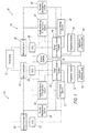
- Figure 1 illustrates an electrical system 10 in which a power plant or engine 12, such as a gas turbine engine, provides electrical power to a first power circuit 14 and a second power circuit 16.
- a system controller 18 is coupled to engine 12 and also to first and second circuits 14, 16.
- First power circuit 14 includes a motor/generator 20 and a General Control Unit (GCU) 22 coupled thereto.
- GCU 22 is also coupled to other components within first power circuit 14, such as a health monitoring and prognostics system 24, a thermal management system 26, and a power conversion/distribution system 28.
- First power circuit 14 also includes an energy storage system 30, an expansion module 32, and application electrical load(s) 34.
- System controller 18 is configured to regulate power flow (such as electrical currents and voltages within system 10) to provide power to various electrical busses.
- System controller 18 may also be configured to execute computer program instructions to control the operation of engine 12, including fuel flow, or the position of any variable geometry systems (e.g., from the flight control system of an aircraft or from a steering system of a ship).
- Health monitoring and prognostics system 24 is generally a unit that monitors the health of system components, and may be used to estimate component life based on sensor feedback received from components within engine 12.
- Thermal management system 26 includes pumps, expansion valves, and the like, as well as a controller, to provide coolant for the purposes of climate control, and other system operations.
- Power conversion/distribution system 28 receives electrical power from motor/generator 20 via GCU 22, and converts the power to a more useable form such as a DC voltage for storage in energy storage system 30, expansion module 32, and application electrical load(s) 34.
- the energy storage system 30 may include a battery or other energy storage system.
- Energy storage system 30 stores energy for providing power when engine 12 is not running (i.e., not generating power), but also to provide power to motor/generator 20 to provide starting power to engine 12 during startup.
- Expansion module 32 and application electrical load 34 represent additional electrical components that receive power from power conversion/distribution system 28.
- Second power circuit 16 similarly includes a motor/generator 36 and a GCU 38 coupled thereto. GCU 38 is also coupled to other components within second power circuit 16, such as a health monitoring and prognostics system 40, a thermal management system 42, and a power conversion/distribution system 44. Second power circuit 16 also includes an energy storage system 46, an expansion module 48, and application electrical load(s) 50. The components 36-50 of second power circuit 16 are similarly arranged as described with respect to first power circuit 14. Additionally, in one example electrical system 10 includes one or more additional motor/generators 52 and corresponding GCUs 54 as well, which may be coupled to a gas turbine engine as will be further described. Thus, the system 10 is modular and flexible in that it may be expanded to include a number N of motor/generators based on contemplated operating conditions.
- Figure 2 illustrates a gas turbine engine 200, which includes a fan 202, a low pressure compressor and a high pressure compressor, 204 and 206, a combustor 208, and a high pressure turbine and low pressure turbine, 210 and 212, respectively.
- the high pressure compressor 206 is connected to a first rotor shaft 214 while the low pressure compressor 204 is connected to a second rotor shaft 216.
- the shafts extend axially and are parallel to a longitudinal center line axis 218.
- Ambient air 220 enters the fan 202 and is directed across a fan rotor 222 in an annular duct 224, which in part is circumscribed by fan case 226.
- Bypass airflow 228 provides engine thrust while a primary gas stream 230 is directed to a combustor 232 and the high pressure turbine 210.
- First and second rotor shafts 214, 216 are coupled, respectively, to first and second power circuits 14, 16, as illustrated in Figure 1 .
- first and second power circuits 14, 16 are configured to split power between motor/generators 20, 36 so that each provides a portion of the power demand.
- a power sharing/transfer arrangement between motor/generators 20, 36 provides the platform power demand, and includes a capability to provide power to one of the shafts 214, 216, as necessary.
- Such arrangement also provides an ability to optimize load shedding and a demand side management of the power requirement.
- life and performance considerations may be taken into account in real-time and optimized to actively seek and obtain performance optima while equipment is in operation.
- Figures 3A and 3B illustrate a modular power electronics distribution system 300.
- the system 300 may be incorporated into power conversion/distribution systems 28, 44 of the electrical system 10.
- the modular power electronics distribution system 300 may be associated with various electrical systems and components in an aircraft, ship, train, laboratory facility, etc.
- the system 300 may be configured to receive various power inputs, for example input form motor/generators 20, 26 and energy storage systems 30, 46.
- the modular power electronics distribution system 300 may be operable to convert the power input into an appropriate electrical power for various loads and/or sources, including but not limited to an air conditioning system, weapon system, navigation system, cabin air compressor, braking system, starter generators, ground power carts, etc.
- the modular power electrical distribution system 300 may include modules 302 comprising both common and functional components 304, 306.
- Traditional distribution designs generally use a backplane approach where the backplane (e.g., distribution box or cabinet) contains all the hardware common in the system and the individual modules contain only the equipment performing a single function assigned to that module.
- the backplane e.g., distribution box or cabinet
- individual modules e.g., individual converter boxes (e.g., a dedicated DC-DC converter from 270 V to 28V) connected with the distribution box containing common hardware, such as the bus, wiring, and cooling system.
- the distribution box was generally designed as an enclosure which needed to be sized to accommodate the maximum possible number of converter boxes in the system, which could vary from system to system.
- the modular power electrical distribution system 300 segments the "common" hardware and adds a functional segment to each module such that, when mated the collection/plurality of modules contain both functional as well as common hardware. Accordingly, lighter and more efficient units may be built due to the shared/common hardware. In like manner, duplicability is easily achieved allowing malfunctioning modules to be conveniently removed and replaced.
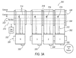
- FIG. 3A illustrates one example of the modular power electronics distribution system 300.
- the system 300 may include a plurality of modules 302, each including a common segment 304 in communication with a functional segment 306.
- the common segment 304 may include the backplane elements such as a power bus network 308, which may include one or more buses 308, wiring circuitry (not shown), and electrical filters (not shown) configured to perform signal processing (e.g., to reduce AC or DC ripple).
- the common segment 304 may include the communication and low power/voltage harnesses 310 configured to transmit commands to the functional segment 306.
- Fault isolation circuitry 312, such as electronic breakers and switches, may be included to protect the module 302 from power surges.
- the fault isolation circuitry 312 may trip and disconnect the module 302 from a load. If a module 302 includes more than one power bus 308, each may include fault isolation circuitry 312. Additionally, the common segment 304 may include cooling system 314 including coolant inlet and return lines that may provide coolant to the functional segment 306 as well as a metering and cutoff valve 316 which monitor the flow of coolant.
- the components of the common segment 304 may be electrically and thermally coupled to the functional segment 306.
- the functional segment 306 may provide electrical power in the required form to various loads and/or sources.
- a non-exhaustive exemplary list of actions the function segment 306 may be operable to perform may include a DC-DC converter providing uni-directional power, a DC-DC converter providing bi-directional power, DC-AC inverter, AC-DC rectifier, or a bi-directional DC-AC inverter/rectifier.
- the module 302 may be configured to provide power for a 28 V DC load, 400 Hz loads, High Frequency loads, supply 115 V three-phase power to AC loads, provide power to motor/generator 20, 36, hydraulic loads, merely as examples.
- the modular power electronics distribution system 300 may provide integrated distribution of power to various loads.
- exemplary modular power electrical distribution system 300 is illustrated according to another example.
- the system 300 may include all the elements incorporated into Figure 3A , but may further include a second common hardware segment 320 on the load or source side of the functional element 306.
- Segment 320 may include the elements associated with common segment 304, including a second fault isolation circuitry 322.
- the faulty functional segment 306 may be isolated on both sides of the functional segment 306 near the source of the fault.
- the plurality of modules 302 may be interconnected through a pluggable interface 318.
- the interface 318 may include a standard interface such that modules 302 may be freely switched or exchanged with one another, thereby allowing the modular power electrical distribution system 300 to be customized to the electrical load and/or source configuration of the associated electrical system.
- the pluggable interface 318 enables any number of modules 302 to be stacked or mated in the system 300, as illustrated in Figures 3A and 3B as module N, as the number of modules 302 is not limited to the size of a cabinet/enclosure.
- Interface 318 may facilitate transmission of electrical power and signals, provide electrical shielding and coolant sealing, and additionally provide mechanical structure between modules 302. Accordingly, the pluggable interface 318 may serve as the distribution, with each individual module 302 comprising the distribution elements. In this way, the distribution is not limited to a maximum number of modules 302.
- the system 300 may additionally include module-to-module mechanical interfaces 324 to provide further mechanical structure between the modules 302.
- the modules 302 at the end of the stung/row of modules 302 may include a mechanical interface 326 to an external structure.
- the module 302 at the end of the string in the system 300 may include a termination plug 328 for the cooling system 314, and to provide electrical isolation from the bus (or buses).
- Each module 302 may include an electrical interface 330 which couples the module 302 to the load and/or source, e.g., transmits the electrical power from the functional segment 306 to the load or source.
- the electrical interface 330 may be in electrical communication with at least one load or source, such as for example a starter/generator, ground power cart, 400 Hz load, hydraulic loads, etc. Additionally or alternatively, each module 302 may have multiple connections to loads/sources, such that each module 302, via the functional segment 306, is configured to drive multiple loads and/or sources simultaneously.
- load or source such as for example a starter/generator, ground power cart, 400 Hz load, hydraulic loads, etc.
- each module 302 may have multiple connections to loads/sources, such that each module 302, via the functional segment 306, is configured to drive multiple loads and/or sources simultaneously.
- the system 300 may include a system controller 332 integrally coupled to the plurality of modules 302.
- the controller 332 may be operable to integrally control the distribution of power across the system 300. Additionally or alternatively, the controller 332 may be configured to control the distribution of coolant via the metering and cutoff valves 316.
- the controller 332 may include any computing device configured to execute computer-readable instructions.
- the controller 332 may include a processor (not shown) and a module (not shown).
- the processor may be integrated with, or separate from, the controller 332.
- the controller 332 may include various modules, each configured to communicate with the processor via a gateway module. Additionally or alternatively, the system 300 may include multiple controllers, each including a processor and module.
- the controller 332 may be configured to perform the functions of controller 18, and vice versa, or may otherwise be integrated with controller 18.
- the controller 332 may be configured to receive various inputs and generate and deliver various outputs in accordance with the inputs received or computer-executable instructions maintained in a database (not shown).
- controller 332 may employ any number of computer operations. It will be apparent to those skilled in the art from the disclosure that the precise hardware and software of the controller 332 and processor may be any combination sufficient to carry out the functions of the examples discussed herein.
- Controller 332 may be configured to receive input from various sensors and sensor systems, including but not limited to, coolant flow, electrical current, motor/generator 20, 36 output, load/source demands, etc.
- the controller 332 may be operable to control and manage the function of various components of the system 300 in response to detected sensor input.
- the controller 332 may be in communication with the plurality of modules 302 via interfaces (not shown).
- the interfaces may include an input/output system configured to transmit and receive data from the respective components.
- the interfaces may be one-directional such that data may only be transmitted in one direction, e.g., from the controller 332 to a module 302.
- the interfaces may be bi-directional, allowing both receiving and transmitting data between the components.
- the controller 332 may be in communication with the fault isolation circuitry 312, 322.
- the controller 332 may monitor the electrical current, via current sensors (not shown), and if the output exceeds or otherwise triggers a threshold value, the controller 332 may trip switch 312 and/or 322.
- the controller 332 may be configured to periodically check if the breaker/switch 312, 322 has been tripped and re-enable the breaker/switch 312, 322 to see if the fault still exists. Consequently, the controller's 332 management over the fault isolation circuitry 312, 322 may eliminate module 302 disconnects caused by source or load transients.
- the controller 332 may communicate with the health monitoring and prognostics (HMP) system 24, 40 to quantify, via a memory or database, the number and location of faults, and the electrical current associated with each fault. If a module 302 faults or otherwise fails, the controller 332 may isolate or disconnect the module 302 until later service (e.g., by disconnecting the circuitry via switch 312 and/or 322).
- HMP health monitoring and prognostics
- the controller 332 may be configured to divert power to a secondary module 302 in response to detecting a fault in a primary module 302.
- the controller 332 may switch in a module 302 as a substitute to provide electrical power to a load or source if the primary module 302 fails. That is, a module 302 driving non-critical loads/sources may be switched in to take over for the module 302 that fails.
- the controller 332 may direct the module 302 labeled 3 (or the module 302 labeled 2, or others such as N) to provide the necessary electrical power required for the 270 V DC load.
- the controller 332 integrates the plurality of modules 302 to thereby optimize power distribution, thus eliminating the complexity of dedicated converters, inverters, and rectifiers.
- the controller 332 may monitor and regulate the thermal energy dispersed across the system 300.
- the controller 332 may be configured to control the flow of coolant between and within each module 302 via the cooling system 314. For example, the controller 332 may regulate the flow of coolant to each module 302 by actuating the valves 316 between 100% open and 100% closed in response to increased operating temperature or work. Additionally, the controller 332 may be configured to increase/decrease coolant flow to modules 302 in response to the modules 302 differing in temperature in relation to one another past a threshold differential. For example, if one module 302 is operating at a higher temperature in relation to the other modules 302, the controller 332 may increase the coolant flow to that module 302 until the temperature decreases below the threshold.
- the controller 332 may operate together with controller 18 and thermal management systems 26, 42 to increase/decrease coolant to one or more modules 302 in response changed operating temperatures.
- the system 300 illustrated in Figure 3A and 3B can serve as a standard platform which may be customized/tailored to fit the requirements of a given engine.
- the pluggable interface 318 allows for easy substitution and replacement of the modules 302.
- the system 300 may be formatted based on specific load requirements or demands.
- the configuration of modules 302 having particular functional segments 306 e.g., DC-AC inverter, AC-DC rectifier, DC-DC converter, etc
- the configuration of modules 302 having particular functional segments 306 may be based on estimated/predicted operating conditions and/or mission requirements.
- they system 300 configuration may be based on determined load requirements over multiple missions.
- modules 302 having a specific functional segment 306 over an aircraft engine which undergoes steady acceleration and consistent cruise speeds.
- the platform for both types of engines may be the same, with differing configurations of the modules 302.
- the pluggable interface 318 removes the necessity of an enclosure (e.g., a chassis or cabinet) to house the individual modules 302 as was required for traditional designs.
- Mechanical structure is achieved through the pluggable interface 318 and optionally the mechanical interfaces 324 and 326.
- the number of modules 302 included in system 300 is not limited to the size of the cabinet or limited to pre-allocated number of modules 302 because there is no enclosure, thus expandability is easily achieved. Consequently, mass and volume savings are achieved because the extra enclosure is not required to contain the converter and distribution elements. Similarly, cost is reduced due to the elimination of excess materials such as the enclosure.
- Each module 302 may be operable to perform variable power sharing to provide power to the electrical loads and/or sources.
- the modules 302 may be configured to provide electrical power in parallel equally, or in different proportions to one another (e.g., 75% : 25%). Indeed, two or more modules 302 may be stacked in parallel and connected simultaneously to a load or source so that electrical power can be shared between the modules 302. For instance, two modules 302 configured to supply 50 kW each may provide power in tandem to a 100 kW load. Similarly, multiple modules 302 may be operable to supply electrical power to a common source such as a starter/generator. Additionally or alternatively, the modules 302 may be configured to perform multiple functions or supply multiple loads and/or sources individually.
- a module 302 may be configured to supply a variety of loads/sources at different times, or may be configured to supply power to multiple loads and/or sources simultaneously.
- a module 302 may be operable to power to a hydraulic load and a 400 Hz load simultaneously.
- a module 302 may be configured to drive a load (e.g., 270 V DC load, 100 kW load, etc.) and a source (e.g., generator, ground power cart, etc.) simultaneously.
- a load e.g., 270 V DC load, 100 kW load, etc.
- a source e.g., generator, ground power cart, etc.
- Computing devices such as system 10 generally include computer-executable instructions such as the instructions of the system controller 18, where the instructions may be executable by one or more computing devices such as those listed above.
- Computer-executable instructions may be compiled or interpreted from computer programs created using a variety of programming languages and/or technologies, including, without limitation, and either alone or in combination, JavaTM, C, C++, C#, Objective C, Visual Basic, Java Script, Perl, etc.
- a processor e.g., a microprocessor
- receives instructions e.g., from a memory, a computer-readable medium, etc., and executes these instructions, thereby performing one or more processes, including one or more of the processes described herein.
- Such instructions and other data may be stored and transmitted using a variety of computer-readable media.
- a computer-readable medium includes any non-transitory (e.g., tangible) medium that participates in providing data (e.g., instructions) that may be read by a computer (e.g., by a processor of a computer).
- a medium may take many forms, including, but not limited to, non-volatile media and volatile media.
- Non-volatile media may include, for example, optical or magnetic disks and other persistent memory.
- Volatile media may include, for example, dynamic random access memory (DRAM), which typically constitutes a main memory.
- Such instructions may be transmitted by one or more transmission media, including coaxial cables, copper wire and fiber optics, including the wires that comprise a system bus coupled to a processor of a computer.
- Computer-readable media include, for example, a floppy disk, a flexible disk, hard disk, magnetic tape, any other magnetic medium, a CD-ROM, DVD, any other optical medium, punch cards, paper tape, any other physical medium with patterns of holes, a RAM, a PROM, an EPROM, a FLASH-EEPROM, any other memory chip or cartridge, or any other medium from which a computer can read.
- Databases, data repositories or other data stores described herein may include various kinds of mechanisms for storing, accessing, and retrieving various kinds of data, including a hierarchical database, a set of files in a file system, an application database in a proprietary format, a relational database management system (RDBMS), etc.
- Each such data store is generally included within a computing device employing a computer operating system such as one of those mentioned above, and are accessed via a network in any one or more of a variety of manners.
- a file system may be accessible from a computer operating system, and may include files stored in various formats.
- An RDBMS generally employs the Structured Query Language (SQL) in addition to a language for creating, storing, editing, and executing stored procedures, such as the PL/SQL language mentioned above.
- SQL Structured Query Language
- system elements may be implemented as computer-readable instructions (e.g., software) on one or more computing devices (e.g., servers, personal computers, etc.), stored on computer readable media associated therewith (e.g., disks, memories, etc.).
- a computer program product may comprise such instructions stored on computer readable media for carrying out the functions described herein.
Landscapes
- Engineering & Computer Science (AREA)
- Power Engineering (AREA)
- Chemical & Material Sciences (AREA)
- Combustion & Propulsion (AREA)
- Microelectronics & Electronic Packaging (AREA)
- Mechanical Engineering (AREA)
- General Engineering & Computer Science (AREA)
- Physics & Mathematics (AREA)
- Thermal Sciences (AREA)
- Inverter Devices (AREA)
Abstract
Description
- This application claims priority to
U.S. Provisional Patent Application No. 61/915,899 filed December 13, 2013 - An improved integrated design and control of a gas turbine is disclosed. More particularly, performance and efficiency are improved by optimizing size and usage of components of a gas turbine, the components including propulsion, thermal, electrical, and control systems, as examples. The improvements are applicable to turbines used for propulsive power in marine, land, air, and underwater applications, as examples.
- It has become increasingly desirable to improve the overall system design and operation of gas turbines. In a system having a typical gas turbine engine, electrical power is extracted via an electrical generator to supply electrical power to control systems, actuators, weapons systems, climate control systems, and the like. Electrical storage, such as a battery, is typically provided to operate such systems when the gas turbine engine is not running or to provide power for starting the gas turbine engine. In some known gas turbine engines, the gas turbine engine includes a high pressure shaft and a lower pressure shaft, and the electrical generator is coupled to one of the high and low pressure shafts.
- However, extraction of power from the gas turbine engine via one of the shafts itself typically results in a loss in overall system life, and in particular to the components of the engine to which the electrical generator is coupled.
- Overcoming these concerns would be desirable and could save the industry substantial resources.
- While the claims are not limited to a specific illustration, an appreciation of the various aspects is best gained through a discussion of various examples thereof. Referring now to the drawings, exemplary illustrations are shown in detail. Although the drawings represent the illustrations, the drawings are not necessarily to scale and certain features may be exaggerated to better illustrate and explain an innovative aspect of an example. Further, the exemplary illustrations described herein are not intended to be exhaustive or otherwise limiting or restricted to the precise form and configuration shown in the drawings and disclosed in the following detailed description. Exemplary illustrations are described in detail by referring to the drawings as follows:
-
FIG. 1 is a schematic illustration of an electrical system coupled to a gas turbine engine, according to one example; -
FIG. 2 illustrates an exemplary gas turbine engine that incorporates the electrical system illustrated inFIG. 1 ; -
FIG. 3A illustrates a modular power electronics distribution system according to one example; and -
FIG. 3B illustrates a modular power electronics distribution system according to another example. - An exemplary gas turbine engine and schematic of an electrical system coupled thereto are described herein and are shown in the attached drawings. The electrical system includes at least two generator circuits, one coupled to a high pressure portion of a gas turbine engine and the other coupled to a low pressure portion of the gas turbine engine.
-
Figure 1 illustrates anelectrical system 10 in which a power plant orengine 12, such as a gas turbine engine, provides electrical power to afirst power circuit 14 and asecond power circuit 16. Asystem controller 18 is coupled toengine 12 and also to first andsecond circuits First power circuit 14 includes a motor/generator 20 and a General Control Unit (GCU) 22 coupled thereto. GCU 22 is also coupled to other components withinfirst power circuit 14, such as a health monitoring andprognostics system 24, athermal management system 26, and a power conversion/distribution system 28.First power circuit 14 also includes anenergy storage system 30, anexpansion module 32, and application electrical load(s) 34.System controller 18 is configured to regulate power flow (such as electrical currents and voltages within system 10) to provide power to various electrical busses. The power may be DC, AC, or conversion therebetween.System controller 18 may also be configured to execute computer program instructions to control the operation ofengine 12, including fuel flow, or the position of any variable geometry systems (e.g., from the flight control system of an aircraft or from a steering system of a ship). - Health monitoring and
prognostics system 24 is generally a unit that monitors the health of system components, and may be used to estimate component life based on sensor feedback received from components withinengine 12.Thermal management system 26 includes pumps, expansion valves, and the like, as well as a controller, to provide coolant for the purposes of climate control, and other system operations. Power conversion/distribution system 28 receives electrical power from motor/generator 20 viaGCU 22, and converts the power to a more useable form such as a DC voltage for storage inenergy storage system 30,expansion module 32, and application electrical load(s) 34. Theenergy storage system 30 may include a battery or other energy storage system.Energy storage system 30 stores energy for providing power whenengine 12 is not running (i.e., not generating power), but also to provide power to motor/generator 20 to provide starting power toengine 12 during startup.Expansion module 32 and applicationelectrical load 34 represent additional electrical components that receive power from power conversion/distribution system 28. -
Second power circuit 16 similarly includes a motor/generator 36 and aGCU 38 coupled thereto. GCU 38 is also coupled to other components withinsecond power circuit 16, such as a health monitoring andprognostics system 40, athermal management system 42, and a power conversion/distribution system 44.Second power circuit 16 also includes anenergy storage system 46, anexpansion module 48, and application electrical load(s) 50. The components 36-50 ofsecond power circuit 16 are similarly arranged as described with respect tofirst power circuit 14. Additionally, in one exampleelectrical system 10 includes one or more additional motor/generators 52 and correspondingGCUs 54 as well, which may be coupled to a gas turbine engine as will be further described. Thus, thesystem 10 is modular and flexible in that it may be expanded to include a number N of motor/generators based on contemplated operating conditions. -
Figure 2 illustrates agas turbine engine 200, which includes afan 202, a low pressure compressor and a high pressure compressor, 204 and 206, acombustor 208, and a high pressure turbine and low pressure turbine, 210 and 212, respectively. Thehigh pressure compressor 206 is connected to afirst rotor shaft 214 while thelow pressure compressor 204 is connected to asecond rotor shaft 216. The shafts extend axially and are parallel to a longitudinalcenter line axis 218.Ambient air 220 enters thefan 202 and is directed across afan rotor 222 in anannular duct 224, which in part is circumscribed byfan case 226. Bypassairflow 228 provides engine thrust while aprimary gas stream 230 is directed to acombustor 232 and thehigh pressure turbine 210. - First and
second rotor shafts second power circuits Figure 1 . Thus, first andsecond power circuits generators generators shafts -
Figures 3A and3B illustrate a modular powerelectronics distribution system 300. Thesystem 300 may be incorporated into power conversion/distribution systems electrical system 10. The modular powerelectronics distribution system 300 may be associated with various electrical systems and components in an aircraft, ship, train, laboratory facility, etc. Thesystem 300 may be configured to receive various power inputs, for example input form motor/generators energy storage systems electronics distribution system 300 may be operable to convert the power input into an appropriate electrical power for various loads and/or sources, including but not limited to an air conditioning system, weapon system, navigation system, cabin air compressor, braking system, starter generators, ground power carts, etc. - The modular power
electrical distribution system 300 may includemodules 302 comprising both common andfunctional components electrical distribution system 300, however, segments the "common" hardware and adds a functional segment to each module such that, when mated the collection/plurality of modules contain both functional as well as common hardware. Accordingly, lighter and more efficient units may be built due to the shared/common hardware. In like manner, duplicability is easily achieved allowing malfunctioning modules to be conveniently removed and replaced. -
Figure 3A illustrates one example of the modular powerelectronics distribution system 300. Thesystem 300 may include a plurality ofmodules 302, each including acommon segment 304 in communication with afunctional segment 306. Thecommon segment 304 may include the backplane elements such as apower bus network 308, which may include one ormore buses 308, wiring circuitry (not shown), and electrical filters (not shown) configured to perform signal processing (e.g., to reduce AC or DC ripple). Likewise, thecommon segment 304 may include the communication and low power/voltage harnesses 310 configured to transmit commands to thefunctional segment 306.Fault isolation circuitry 312, such as electronic breakers and switches, may be included to protect themodule 302 from power surges. For example, if the electrical current exceeds a predefined threshold, thefault isolation circuitry 312 may trip and disconnect themodule 302 from a load. If amodule 302 includes more than onepower bus 308, each may includefault isolation circuitry 312. Additionally, thecommon segment 304 may includecooling system 314 including coolant inlet and return lines that may provide coolant to thefunctional segment 306 as well as a metering andcutoff valve 316 which monitor the flow of coolant. - The components of the
common segment 304 may be electrically and thermally coupled to thefunctional segment 306. Thefunctional segment 306 may provide electrical power in the required form to various loads and/or sources. A non-exhaustive exemplary list of actions thefunction segment 306 may be operable to perform may include a DC-DC converter providing uni-directional power, a DC-DC converter providing bi-directional power, DC-AC inverter, AC-DC rectifier, or a bi-directional DC-AC inverter/rectifier. Thus, for example, themodule 302 may be configured to provide power for a 28 V DC load, 400 Hz loads, High Frequency loads, supply 115 V three-phase power to AC loads, provide power to motor/generator electronics distribution system 300 may provide integrated distribution of power to various loads. - With reference to
Figure 3B , exemplary modular powerelectrical distribution system 300 is illustrated according to another example. Thesystem 300 may include all the elements incorporated intoFigure 3A , but may further include a secondcommon hardware segment 320 on the load or source side of thefunctional element 306.Segment 320 may include the elements associated withcommon segment 304, including a secondfault isolation circuitry 322. As such, the faultyfunctional segment 306 may be isolated on both sides of thefunctional segment 306 near the source of the fault. - Referring to
Figures 3A and3B , the plurality ofmodules 302 may be interconnected through apluggable interface 318. Theinterface 318 may include a standard interface such thatmodules 302 may be freely switched or exchanged with one another, thereby allowing the modular powerelectrical distribution system 300 to be customized to the electrical load and/or source configuration of the associated electrical system. Additionally, thepluggable interface 318 enables any number ofmodules 302 to be stacked or mated in thesystem 300, as illustrated inFigures 3A and3B as module N, as the number ofmodules 302 is not limited to the size of a cabinet/enclosure.Interface 318 may facilitate transmission of electrical power and signals, provide electrical shielding and coolant sealing, and additionally provide mechanical structure betweenmodules 302. Accordingly, thepluggable interface 318 may serve as the distribution, with eachindividual module 302 comprising the distribution elements. In this way, the distribution is not limited to a maximum number ofmodules 302. - The
system 300 may additionally include module-to-modulemechanical interfaces 324 to provide further mechanical structure between themodules 302. Optionally, themodules 302 at the end of the stung/row ofmodules 302 may include amechanical interface 326 to an external structure. Themodule 302 at the end of the string in thesystem 300 may include atermination plug 328 for thecooling system 314, and to provide electrical isolation from the bus (or buses). Eachmodule 302 may include anelectrical interface 330 which couples themodule 302 to the load and/or source, e.g., transmits the electrical power from thefunctional segment 306 to the load or source. That is, theelectrical interface 330 may be in electrical communication with at least one load or source, such as for example a starter/generator, ground power cart, 400 Hz load, hydraulic loads, etc. Additionally or alternatively, eachmodule 302 may have multiple connections to loads/sources, such that eachmodule 302, via thefunctional segment 306, is configured to drive multiple loads and/or sources simultaneously. - The
system 300 may include asystem controller 332 integrally coupled to the plurality ofmodules 302. Thecontroller 332 may be operable to integrally control the distribution of power across thesystem 300. Additionally or alternatively, thecontroller 332 may be configured to control the distribution of coolant via the metering andcutoff valves 316. Thecontroller 332 may include any computing device configured to execute computer-readable instructions. For example, thecontroller 332 may include a processor (not shown) and a module (not shown). The processor may be integrated with, or separate from, thecontroller 332. Alternatively, thecontroller 332 may include various modules, each configured to communicate with the processor via a gateway module. Additionally or alternatively, thesystem 300 may include multiple controllers, each including a processor and module. Thecontroller 332 may be configured to perform the functions ofcontroller 18, and vice versa, or may otherwise be integrated withcontroller 18. Thecontroller 332 may be configured to receive various inputs and generate and deliver various outputs in accordance with the inputs received or computer-executable instructions maintained in a database (not shown). - In general, computing systems and/or devices, such as the
controller 332 and processor may employ any number of computer operations. It will be apparent to those skilled in the art from the disclosure that the precise hardware and software of thecontroller 332 and processor may be any combination sufficient to carry out the functions of the examples discussed herein.Controller 332 may be configured to receive input from various sensors and sensor systems, including but not limited to, coolant flow, electrical current, motor/generator controller 332 may be operable to control and manage the function of various components of thesystem 300 in response to detected sensor input. - The
controller 332 may be in communication with the plurality ofmodules 302 via interfaces (not shown). The interfaces may include an input/output system configured to transmit and receive data from the respective components. The interfaces may be one-directional such that data may only be transmitted in one direction, e.g., from thecontroller 332 to amodule 302. Alternatively, the interfaces may be bi-directional, allowing both receiving and transmitting data between the components. - The
controller 332 may be in communication with thefault isolation circuitry controller 332 may monitor the electrical current, via current sensors (not shown), and if the output exceeds or otherwise triggers a threshold value, thecontroller 332 may tripswitch 312 and/or 322. Thecontroller 332 may be configured to periodically check if the breaker/switch switch fault isolation circuitry module 302 disconnects caused by source or load transients. - The
controller 332 may communicate with the health monitoring and prognostics (HMP)system module 302 faults or otherwise fails, thecontroller 332 may isolate or disconnect themodule 302 until later service (e.g., by disconnecting the circuitry viaswitch 312 and/or 322). The stackable or pluggable design of thesystem 300 enables easy substitution/replacement of the faulty or malfunctioningmodules 302 without having to sacrifice the performance or life of thehealthy modules 302. - Additionally, the
controller 332 may be configured to divert power to asecondary module 302 in response to detecting a fault in aprimary module 302. Thecontroller 332 may switch in amodule 302 as a substitute to provide electrical power to a load or source if theprimary module 302 fails. That is, amodule 302 driving non-critical loads/sources may be switched in to take over for themodule 302 that fails. For example, with reference toFigure 3A , if themodule 302 labeled 1 is the primarypower distribution module 302 for a load, such as 270 V DC load, and faults or otherwise fails, thecontroller 332 may direct themodule 302 labeled 3 (or themodule 302 labeled 2, or others such as N) to provide the necessary electrical power required for the 270 V DC load. As such, thecontroller 332 integrates the plurality ofmodules 302 to thereby optimize power distribution, thus eliminating the complexity of dedicated converters, inverters, and rectifiers. - The
controller 332 may monitor and regulate the thermal energy dispersed across thesystem 300. Thecontroller 332 may be configured to control the flow of coolant between and within eachmodule 302 via thecooling system 314. For example, thecontroller 332 may regulate the flow of coolant to eachmodule 302 by actuating thevalves 316 between 100% open and 100% closed in response to increased operating temperature or work. Additionally, thecontroller 332 may be configured to increase/decrease coolant flow tomodules 302 in response to themodules 302 differing in temperature in relation to one another past a threshold differential. For example, if onemodule 302 is operating at a higher temperature in relation to theother modules 302, thecontroller 332 may increase the coolant flow to thatmodule 302 until the temperature decreases below the threshold. Thecontroller 332 may operate together withcontroller 18 andthermal management systems more modules 302 in response changed operating temperatures. - The
system 300 illustrated inFigure 3A and3B can serve as a standard platform which may be customized/tailored to fit the requirements of a given engine. Thepluggable interface 318 allows for easy substitution and replacement of themodules 302. Accordingly, thesystem 300 may be formatted based on specific load requirements or demands. For example, the configuration ofmodules 302 having particular functional segments 306 (e.g., DC-AC inverter, AC-DC rectifier, DC-DC converter, etc) may be based on estimated/predicted operating conditions and/or mission requirements. Likewise, theysystem 300 configuration may be based on determined load requirements over multiple missions. An aircraft, for instance, which undergoes extreme thrust and aerial maneuvers may require a different configuration ofmodules 302 having a specificfunctional segment 306 over an aircraft engine which undergoes steady acceleration and consistent cruise speeds. However, the platform for both types of engines may be the same, with differing configurations of themodules 302. - Advantageously, the
pluggable interface 318 removes the necessity of an enclosure (e.g., a chassis or cabinet) to house theindividual modules 302 as was required for traditional designs. Mechanical structure is achieved through thepluggable interface 318 and optionally themechanical interfaces modules 302 included insystem 300 is not limited to the size of the cabinet or limited to pre-allocated number ofmodules 302 because there is no enclosure, thus expandability is easily achieved. Consequently, mass and volume savings are achieved because the extra enclosure is not required to contain the converter and distribution elements. Similarly, cost is reduced due to the elimination of excess materials such as the enclosure. - Each
module 302 may be operable to perform variable power sharing to provide power to the electrical loads and/or sources. Themodules 302 may be configured to provide electrical power in parallel equally, or in different proportions to one another (e.g., 75% : 25%). Indeed, two ormore modules 302 may be stacked in parallel and connected simultaneously to a load or source so that electrical power can be shared between themodules 302. For instance, twomodules 302 configured to supply 50 kW each may provide power in tandem to a 100 kW load. Similarly,multiple modules 302 may be operable to supply electrical power to a common source such as a starter/generator. Additionally or alternatively, themodules 302 may be configured to perform multiple functions or supply multiple loads and/or sources individually. Amodule 302 may be configured to supply a variety of loads/sources at different times, or may be configured to supply power to multiple loads and/or sources simultaneously. For example, amodule 302 may be operable to power to a hydraulic load and a 400 Hz load simultaneously. Similarly, amodule 302 may be configured to drive a load (e.g., 270 V DC load, 100 kW load, etc.) and a source (e.g., generator, ground power cart, etc.) simultaneously. As such,fewer modules 302 than the number of loads and sources may be used without thesystem 300 suffering from mass or volume penalties because one module may have dual roles. - Computing devices such as
system 10 generally include computer-executable instructions such as the instructions of thesystem controller 18, where the instructions may be executable by one or more computing devices such as those listed above. Computer-executable instructions may be compiled or interpreted from computer programs created using a variety of programming languages and/or technologies, including, without limitation, and either alone or in combination, Java™, C, C++, C#, Objective C, Visual Basic, Java Script, Perl, etc. In general, a processor (e.g., a microprocessor) receives instructions, e.g., from a memory, a computer-readable medium, etc., and executes these instructions, thereby performing one or more processes, including one or more of the processes described herein. Such instructions and other data may be stored and transmitted using a variety of computer-readable media. - A computer-readable medium (also referred to as a processor-readable medium) includes any non-transitory (e.g., tangible) medium that participates in providing data (e.g., instructions) that may be read by a computer (e.g., by a processor of a computer). Such a medium may take many forms, including, but not limited to, non-volatile media and volatile media. Non-volatile media may include, for example, optical or magnetic disks and other persistent memory. Volatile media may include, for example, dynamic random access memory (DRAM), which typically constitutes a main memory. Such instructions may be transmitted by one or more transmission media, including coaxial cables, copper wire and fiber optics, including the wires that comprise a system bus coupled to a processor of a computer. Common forms of computer-readable media include, for example, a floppy disk, a flexible disk, hard disk, magnetic tape, any other magnetic medium, a CD-ROM, DVD, any other optical medium, punch cards, paper tape, any other physical medium with patterns of holes, a RAM, a PROM, an EPROM, a FLASH-EEPROM, any other memory chip or cartridge, or any other medium from which a computer can read.
- Databases, data repositories or other data stores described herein may include various kinds of mechanisms for storing, accessing, and retrieving various kinds of data, including a hierarchical database, a set of files in a file system, an application database in a proprietary format, a relational database management system (RDBMS), etc. Each such data store is generally included within a computing device employing a computer operating system such as one of those mentioned above, and are accessed via a network in any one or more of a variety of manners. A file system may be accessible from a computer operating system, and may include files stored in various formats. An RDBMS generally employs the Structured Query Language (SQL) in addition to a language for creating, storing, editing, and executing stored procedures, such as the PL/SQL language mentioned above.
- In some examples, system elements may be implemented as computer-readable instructions (e.g., software) on one or more computing devices (e.g., servers, personal computers, etc.), stored on computer readable media associated therewith (e.g., disks, memories, etc.). A computer program product may comprise such instructions stored on computer readable media for carrying out the functions described herein.
- With regard to the processes, systems, methods, heuristics, etc. described herein, it should be understood that, although the steps of such processes, etc. have been described as occurring according to a certain ordered sequence, such processes could be practiced with the described steps performed in an order other than the order described herein. It further should be understood that certain steps could be performed simultaneously, that other steps could be added, or that certain steps described herein could be omitted. In other words, the descriptions of processes herein are provided for the purpose of illustrating certain embodiments, and should in no way be construed so as to limit the claims.
- All terms used in the claims are intended to be given their broadest reasonable constructions and their ordinary meanings as understood by those knowledgeable in the technologies described herein unless an explicit indication to the contrary in made herein. In particular, use of the singular articles such as "a," "the," "said," etc. should be read to recite one or more of the indicated elements unless a claim recites an explicit limitation to the contrary.
Claims (15)
- A modular power electronics distribution system (300), comprising:a plurality of modules (302) connectable to a pluggable interface (318), the interface (318) configured to receive and distribute power to the plurality of modules (302);wherein the plurality of modules (302) each include:at least one fault isolation switch (312, 322);a coolant system (314) including an inlet and return line, and a metering valve (316);at least one power bus (308) configured to provide electrical power to at least one of a load or source via a functional segment (306), wherein the functional segment (306) is operable to supply electrical power in a desired form to the load; anda controller (332) in communication with the plurality of modules (302), the controller (332) configured to control at least one of the at least one fault isolation switch (312, 332) and the metering valve (316).
- The system as claimed in claim 1, wherein the controller (332) is further configured to manage the distribution of power between the plurality of modules (302) in response to detected load requirements.
- The system as claimed in claims 1 or 2, wherein the controller (332) is configured to detect a fault in response to electrical current tripping the fault isolation switch (312, 322) of at least one module (302) and direct another module (302) to supply power to a load in substitution of the faulty module.
- The system as claimed in claim 3, wherein the controller (332), after detecting the electrical fault, is configured to periodically re-enable the tripped fault isolation switch (312, 322).
- The system as claimed in any of the claims 1 to 4, further comprising a second fault isolation switch (322) arranged in a segment opposite the at least one fault isolation switch (312) relative to the functional segment (306) such that the functional segment (306) can be isolated on both sides.
- The system as claimed in any of the claims 1 to 5, wherein the functional segment (306) includes at least one of a rectifier, an inverter, and a converter, wherein the at least one of the rectifier, inverter, and converter is one of uni-directional and bi-directional capable.
- The system as claimed in any of the claims 1 to 6, wherein at least two modules (302) can supply power to at least one of a common load or a common source.
- The system as claimed in any of the claims 1 to 7, wherein at least one module (302) can supply power to at least one of multiple loads, multiple sources, and at least one load and one source.
- An electrical power and thermal management system (10), comprising:at least one motor/generator (20, 36) operable to provide power to a bus system (308);a power electronics distribution system (300) coupled to the at least one motor/generator (20, 36), the power electronics distribution system (300) comprising:a modular pluggable interface (318) configured to augment distribution of power and coolant;a plurality of modules (302) configured to mate with the interface (318), wherein each module includes:at least one fault isolation switch (312, 322);a coolant system (314) configured to circulate coolant through an inlet line and a return line, wherein the coolant system includes a metering valve (316);at least one power bus (308) configured to deliver power to a functional segment (306), wherein the functional segment (306) is operable to supply an appropriate electrical power to at least one of a load or a source; anda distribution controller (332) operable to control the fault isolation switch (312, 322) and metering valve (316).
- The system as claimed in claim 9, wherein the controller (332) is further configured to control the distribution of power between the plurality of modules (302).
- The system as claimed in claim 10, wherein the at least one module (302) can supply power to at least one of at least two loads, at least two sources, or at least one load and one source.
- The system as claimed in claims 10 or 11, wherein at least two modules (302) supply power to at least one of a common load or a common source.
- The system as claimed in any of the claims 9 to 12, wherein the power electronic distribution system (300) further comprises a second fault isolation switch (322) arranged opposite the first fault isolation switch (312) relative to the functional segment (306) such that the functional segment (306) can be isolated on both sides.
- The system as claimed in any of the claims 9 to 13, wherein the controller (332) is configured to detect a fault in response to tripping the fault isolation switch (312, 322) of at least one module (302), disconnect the at least one faulty module (302), and direct another module (302) to supply supplemental power to a load in lieu of the at least one faulty module (302).
- The system as claimed in any of the claims 9 to 14, wherein the pluggable interface (318) provides electrical shielding and coolant sealing for the distribution of power and coolant between modules (302).
Applications Claiming Priority (1)
| Application Number | Priority Date | Filing Date | Title |
|---|---|---|---|
| US201361915899P | 2013-12-13 | 2013-12-13 |
Publications (2)
| Publication Number | Publication Date |
|---|---|
| EP2884615A1 true EP2884615A1 (en) | 2015-06-17 |
| EP2884615B1 EP2884615B1 (en) | 2017-03-01 |
Family
ID=52015899
Family Applications (1)
| Application Number | Title | Priority Date | Filing Date |
|---|---|---|---|
| EP14196020.3A Active EP2884615B1 (en) | 2013-12-13 | 2014-12-03 | Modular power electronics distribution system |
Country Status (2)
| Country | Link |
|---|---|
| US (1) | US9386730B2 (en) |
| EP (1) | EP2884615B1 (en) |
Cited By (5)
| Publication number | Priority date | Publication date | Assignee | Title |
|---|---|---|---|---|
| EP3190282A1 (en) * | 2016-01-11 | 2017-07-12 | Liebherr-Aerospace Toulouse SAS | Electrical architecture of an aircraft comprising a cooling plate |
| CN109800227A (en) * | 2018-12-26 | 2019-05-24 | 贵州电网有限责任公司 | Dispatching of power netwoks utilization logger system based on Structured Design |
| EP3605772A1 (en) * | 2018-08-03 | 2020-02-05 | Ge Aviation Systems Llc, Inc. | Dynamically configurable energy storage unit |
| CN112315327A (en) * | 2020-10-27 | 2021-02-05 | 珠海格力电器股份有限公司 | Cooking apparatus, control method thereof, control device thereof, and computer-readable storage medium |
| WO2026075871A1 (en) * | 2024-10-01 | 2026-04-09 | Nextpower Llc | Solar power processing modules with self-guiding universal connectors |
Families Citing this family (8)
| Publication number | Priority date | Publication date | Assignee | Title |
|---|---|---|---|---|
| EP2971699B8 (en) | 2013-03-15 | 2020-01-15 | Rolls-Royce Corporation | Lifing and performance optimization limit management for turbine engine |
| EP3031121A4 (en) | 2013-08-06 | 2017-02-15 | Bedrock Automation Platforms Inc. | Smart power system |
| US10205415B2 (en) | 2015-12-14 | 2019-02-12 | Rolls-Royce North American Technologies Inc. | Multiple generator synchronous electrical power distribution system |
| GB2547946B (en) * | 2016-03-04 | 2020-05-20 | Ge Aviat Systems Ltd | Method and apparatus for modular power distribution |
| US11156128B2 (en) | 2018-08-22 | 2021-10-26 | General Electric Company | Embedded electric machine |
| CN110062560B (en) * | 2019-03-14 | 2022-02-25 | 华为技术有限公司 | Heat dissipation method, heat dissipation device, and cabinet |
| US11428168B2 (en) * | 2020-01-06 | 2022-08-30 | Hamilton Sundstrand Corporation | Starter/generator arrangements for gas turbine engines |
| US12149154B2 (en) | 2021-07-22 | 2024-11-19 | General Electric Company | Electric machine having a hybrid insulative-conductive manifold |
Citations (3)
| Publication number | Priority date | Publication date | Assignee | Title |
|---|---|---|---|---|
| US5466974A (en) * | 1993-02-19 | 1995-11-14 | Sundstrand Corporation | Electric power distribution module for an electric power generation and distribution system |
| US20040069251A1 (en) * | 2001-01-22 | 2004-04-15 | Wolfgang Rzadki | Energy system for watercraft |
| EP2077226A2 (en) * | 2008-01-07 | 2009-07-08 | Converteam Technology Ltd | Marine power distribution and propulsion systems |
Family Cites Families (10)
| Publication number | Priority date | Publication date | Assignee | Title |
|---|---|---|---|---|
| US4064630A (en) * | 1972-03-29 | 1977-12-27 | C.M.W. Laboratories Limited | Dental units and the like |
| EP0992430A3 (en) | 1998-10-07 | 2000-09-13 | Negesat Di Boer Fabrizio & C. SNC | Housing providing cooling for equipment aboard aircraft or spacecraft |
| JP2005019562A (en) | 2003-06-24 | 2005-01-20 | Hitachi Ltd | Electronic equipment cooling structure |
| US7671490B2 (en) | 2005-10-17 | 2010-03-02 | Smiths Aerospace Llc | System for high reliability power distribution within an electronics equipment cabinet |
| US8148842B2 (en) | 2006-02-20 | 2012-04-03 | Hamilton Sundstrand Corporation | Electrical power generation system having multiple secondary power distribution assemblies with integral power conversion |
| US7907423B2 (en) | 2007-10-04 | 2011-03-15 | Tyco Electronics Brasil Ltda. | Modular power distribution assembly and method of making same |
| PL2548211T3 (en) | 2010-07-14 | 2015-06-30 | Vito Nv | Method for packaging and connecting ultracapacitors for energy storage purposes especially for a vehicle |
| US10122178B2 (en) * | 2011-04-15 | 2018-11-06 | Deka Products Limited Partnership | Modular power conversion system |
| FR2980459B1 (en) | 2011-09-22 | 2014-06-27 | Airbus Operations Sas | MODULE OF ELECTRICAL DEVICES FOR AVIONIC BAY |
| EP2662879B1 (en) * | 2012-05-07 | 2015-02-25 | ABB S.p.A. | Accessory device assembly for low and medium voltage switching devices |
-
2014
- 2014-11-18 US US14/546,255 patent/US9386730B2/en active Active
- 2014-12-03 EP EP14196020.3A patent/EP2884615B1/en active Active
Patent Citations (3)
| Publication number | Priority date | Publication date | Assignee | Title |
|---|---|---|---|---|
| US5466974A (en) * | 1993-02-19 | 1995-11-14 | Sundstrand Corporation | Electric power distribution module for an electric power generation and distribution system |
| US20040069251A1 (en) * | 2001-01-22 | 2004-04-15 | Wolfgang Rzadki | Energy system for watercraft |
| EP2077226A2 (en) * | 2008-01-07 | 2009-07-08 | Converteam Technology Ltd | Marine power distribution and propulsion systems |
Cited By (8)
| Publication number | Priority date | Publication date | Assignee | Title |
|---|---|---|---|---|
| EP3190282A1 (en) * | 2016-01-11 | 2017-07-12 | Liebherr-Aerospace Toulouse SAS | Electrical architecture of an aircraft comprising a cooling plate |
| FR3046598A1 (en) * | 2016-01-11 | 2017-07-14 | Liebherr-Aerospace Toulouse Sas | ELECTRICAL ARCHITECTURE OF AN AIRCRAFT WITH A COOLING PLATE |
| EP3605772A1 (en) * | 2018-08-03 | 2020-02-05 | Ge Aviation Systems Llc, Inc. | Dynamically configurable energy storage unit |
| CN110797957A (en) * | 2018-08-03 | 2020-02-14 | 通用电气航空系统有限责任公司 | Dynamically configurable energy storage unit |
| CN109800227A (en) * | 2018-12-26 | 2019-05-24 | 贵州电网有限责任公司 | Dispatching of power netwoks utilization logger system based on Structured Design |
| CN109800227B (en) * | 2018-12-26 | 2022-04-22 | 贵州电网有限责任公司 | Power grid dispatching operation recording system based on structural design |
| CN112315327A (en) * | 2020-10-27 | 2021-02-05 | 珠海格力电器股份有限公司 | Cooking apparatus, control method thereof, control device thereof, and computer-readable storage medium |
| WO2026075871A1 (en) * | 2024-10-01 | 2026-04-09 | Nextpower Llc | Solar power processing modules with self-guiding universal connectors |
Also Published As
| Publication number | Publication date |
|---|---|
| EP2884615B1 (en) | 2017-03-01 |
| US9386730B2 (en) | 2016-07-05 |
| US20150173254A1 (en) | 2015-06-18 |
Similar Documents
| Publication | Publication Date | Title |
|---|---|---|
| US9386730B2 (en) | Modular power electronics distribution system | |
| EP2881563B1 (en) | Integrated electrical power and thermal management system | |
| Barzkar et al. | Electric power systems in more and all electric aircraft: A review | |
| EP2889452B1 (en) | System and method for coordinated control of a power system | |
| EP2930335B1 (en) | Fuel-air ratio control of gas turbine engines | |
| US10472078B2 (en) | Hybrid power system for an aircraft | |
| JP5396670B2 (en) | Electrical network management method | |
| EP2972620B1 (en) | Integrated health management approach to propulsion control system protection limiting | |
| EP2887536B1 (en) | Control system for a dual redundant motor/generator and engine | |
| US9653965B2 (en) | Dual redundant motor/generator for an engine | |
| EP3118925B1 (en) | Thermal management of energy storage | |
| EP2937519B1 (en) | Method to control electric starter generator for gas turbine engines | |
| US9435267B2 (en) | Integrated health management approach to propulsion control system protection limiting | |
| EP4428038A1 (en) | Aircraft hybrid electric propulsion architecture enabling modes of operation | |
| Hegner et al. | Integrated fight through power | |
| US20240017844A1 (en) | Aircraft propulsion utilizing a safety critical energy management system | |
| Lay et al. | Layout and testing of a serial hybrid electric powertrain for a light twin demonstrator platform | |
| US20240425189A1 (en) | Aircraft hybrid electric propulsion and attitude controller | |
| Feehally | Electro-mechanical interaction in gas turbine-generator systems for more-electric aircraft | |
| Todd et al. | Effects of electrical power off-take on finite inertia mechanical systems | |
| Espinosa-Juárez et al. | A Review of Aircraft On-Board Systems: in the Context of Energy and Power Management | |
| Vratny et al. | DESIGN AND OFF-DESIGN PERFORMANCE OF ELECTRIC SYSTEM ARCHITECTURES FOR ELECTRIC POWERED AIRCRAFT |
Legal Events
| Date | Code | Title | Description |
|---|---|---|---|
| PUAI | Public reference made under article 153(3) epc to a published international application that has entered the european phase |
Free format text: ORIGINAL CODE: 0009012 |
|
| 17P | Request for examination filed |
Effective date: 20141203 |
|
| AK | Designated contracting states |
Kind code of ref document: A1 Designated state(s): AL AT BE BG CH CY CZ DE DK EE ES FI FR GB GR HR HU IE IS IT LI LT LU LV MC MK MT NL NO PL PT RO RS SE SI SK SM TR |
|
| AX | Request for extension of the european patent |
Extension state: BA ME |
|
| R17P | Request for examination filed (corrected) |
Effective date: 20151216 |
|
| RBV | Designated contracting states (corrected) |
Designated state(s): AL AT BE BG CH CY CZ DE DK EE ES FI FR GB GR HR HU IE IS IT LI LT LU LV MC MK MT NL NO PL PT RO RS SE SI SK SM TR |
|
| GRAP | Despatch of communication of intention to grant a patent |
Free format text: ORIGINAL CODE: EPIDOSNIGR1 |
|
| INTG | Intention to grant announced |
Effective date: 20161011 |
|
| GRAS | Grant fee paid |
Free format text: ORIGINAL CODE: EPIDOSNIGR3 |
|
| GRAA | (expected) grant |
Free format text: ORIGINAL CODE: 0009210 |
|
| AK | Designated contracting states |
Kind code of ref document: B1 Designated state(s): AL AT BE BG CH CY CZ DE DK EE ES FI FR GB GR HR HU IE IS IT LI LT LU LV MC MK MT NL NO PL PT RO RS SE SI SK SM TR |
|
| REG | Reference to a national code |
Ref country code: GB Ref legal event code: FG4D |
|
| REG | Reference to a national code |
Ref country code: CH Ref legal event code: EP Ref country code: AT Ref legal event code: REF Ref document number: 872366 Country of ref document: AT Kind code of ref document: T Effective date: 20170315 |
|
| REG | Reference to a national code |
Ref country code: IE Ref legal event code: FG4D |
|
| REG | Reference to a national code |
Ref country code: DE Ref legal event code: R096 Ref document number: 602014007090 Country of ref document: DE |
|
| REG | Reference to a national code |
Ref country code: NL Ref legal event code: MP Effective date: 20170301 |
|
| REG | Reference to a national code |
Ref country code: LT Ref legal event code: MG4D |
|
| REG | Reference to a national code |
Ref country code: AT Ref legal event code: MK05 Ref document number: 872366 Country of ref document: AT Kind code of ref document: T Effective date: 20170301 |
|
| PG25 | Lapsed in a contracting state [announced via postgrant information from national office to epo] |
Ref country code: HR Free format text: LAPSE BECAUSE OF FAILURE TO SUBMIT A TRANSLATION OF THE DESCRIPTION OR TO PAY THE FEE WITHIN THE PRESCRIBED TIME-LIMIT Effective date: 20170301 Ref country code: FI Free format text: LAPSE BECAUSE OF FAILURE TO SUBMIT A TRANSLATION OF THE DESCRIPTION OR TO PAY THE FEE WITHIN THE PRESCRIBED TIME-LIMIT Effective date: 20170301 Ref country code: GR Free format text: LAPSE BECAUSE OF FAILURE TO SUBMIT A TRANSLATION OF THE DESCRIPTION OR TO PAY THE FEE WITHIN THE PRESCRIBED TIME-LIMIT Effective date: 20170602 Ref country code: LT Free format text: LAPSE BECAUSE OF FAILURE TO SUBMIT A TRANSLATION OF THE DESCRIPTION OR TO PAY THE FEE WITHIN THE PRESCRIBED TIME-LIMIT Effective date: 20170301 Ref country code: NO Free format text: LAPSE BECAUSE OF FAILURE TO SUBMIT A TRANSLATION OF THE DESCRIPTION OR TO PAY THE FEE WITHIN THE PRESCRIBED TIME-LIMIT Effective date: 20170601 |
|
| PG25 | Lapsed in a contracting state [announced via postgrant information from national office to epo] |
Ref country code: ES Free format text: LAPSE BECAUSE OF FAILURE TO SUBMIT A TRANSLATION OF THE DESCRIPTION OR TO PAY THE FEE WITHIN THE PRESCRIBED TIME-LIMIT Effective date: 20170301 Ref country code: RS Free format text: LAPSE BECAUSE OF FAILURE TO SUBMIT A TRANSLATION OF THE DESCRIPTION OR TO PAY THE FEE WITHIN THE PRESCRIBED TIME-LIMIT Effective date: 20170301 Ref country code: LV Free format text: LAPSE BECAUSE OF FAILURE TO SUBMIT A TRANSLATION OF THE DESCRIPTION OR TO PAY THE FEE WITHIN THE PRESCRIBED TIME-LIMIT Effective date: 20170301 Ref country code: BG Free format text: LAPSE BECAUSE OF FAILURE TO SUBMIT A TRANSLATION OF THE DESCRIPTION OR TO PAY THE FEE WITHIN THE PRESCRIBED TIME-LIMIT Effective date: 20170601 Ref country code: AT Free format text: LAPSE BECAUSE OF FAILURE TO SUBMIT A TRANSLATION OF THE DESCRIPTION OR TO PAY THE FEE WITHIN THE PRESCRIBED TIME-LIMIT Effective date: 20170301 Ref country code: SE Free format text: LAPSE BECAUSE OF FAILURE TO SUBMIT A TRANSLATION OF THE DESCRIPTION OR TO PAY THE FEE WITHIN THE PRESCRIBED TIME-LIMIT Effective date: 20170301 |
|
| PG25 | Lapsed in a contracting state [announced via postgrant information from national office to epo] |
Ref country code: NL Free format text: LAPSE BECAUSE OF FAILURE TO SUBMIT A TRANSLATION OF THE DESCRIPTION OR TO PAY THE FEE WITHIN THE PRESCRIBED TIME-LIMIT Effective date: 20170301 |
|
| PG25 | Lapsed in a contracting state [announced via postgrant information from national office to epo] |
Ref country code: SK Free format text: LAPSE BECAUSE OF FAILURE TO SUBMIT A TRANSLATION OF THE DESCRIPTION OR TO PAY THE FEE WITHIN THE PRESCRIBED TIME-LIMIT Effective date: 20170301 Ref country code: EE Free format text: LAPSE BECAUSE OF FAILURE TO SUBMIT A TRANSLATION OF THE DESCRIPTION OR TO PAY THE FEE WITHIN THE PRESCRIBED TIME-LIMIT Effective date: 20170301 Ref country code: CZ Free format text: LAPSE BECAUSE OF FAILURE TO SUBMIT A TRANSLATION OF THE DESCRIPTION OR TO PAY THE FEE WITHIN THE PRESCRIBED TIME-LIMIT Effective date: 20170301 Ref country code: IT Free format text: LAPSE BECAUSE OF FAILURE TO SUBMIT A TRANSLATION OF THE DESCRIPTION OR TO PAY THE FEE WITHIN THE PRESCRIBED TIME-LIMIT Effective date: 20170301 Ref country code: RO Free format text: LAPSE BECAUSE OF FAILURE TO SUBMIT A TRANSLATION OF THE DESCRIPTION OR TO PAY THE FEE WITHIN THE PRESCRIBED TIME-LIMIT Effective date: 20170301 |
|
| PG25 | Lapsed in a contracting state [announced via postgrant information from national office to epo] |
Ref country code: SM Free format text: LAPSE BECAUSE OF FAILURE TO SUBMIT A TRANSLATION OF THE DESCRIPTION OR TO PAY THE FEE WITHIN THE PRESCRIBED TIME-LIMIT Effective date: 20170301 Ref country code: IS Free format text: LAPSE BECAUSE OF FAILURE TO SUBMIT A TRANSLATION OF THE DESCRIPTION OR TO PAY THE FEE WITHIN THE PRESCRIBED TIME-LIMIT Effective date: 20170701 Ref country code: PL Free format text: LAPSE BECAUSE OF FAILURE TO SUBMIT A TRANSLATION OF THE DESCRIPTION OR TO PAY THE FEE WITHIN THE PRESCRIBED TIME-LIMIT Effective date: 20170301 Ref country code: PT Free format text: LAPSE BECAUSE OF FAILURE TO SUBMIT A TRANSLATION OF THE DESCRIPTION OR TO PAY THE FEE WITHIN THE PRESCRIBED TIME-LIMIT Effective date: 20170703 |
|
| REG | Reference to a national code |
Ref country code: DE Ref legal event code: R097 Ref document number: 602014007090 Country of ref document: DE |
|
| REG | Reference to a national code |
Ref country code: FR Ref legal event code: PLFP Year of fee payment: 4 |
|
| PLBE | No opposition filed within time limit |
Free format text: ORIGINAL CODE: 0009261 |
|
| STAA | Information on the status of an ep patent application or granted ep patent |
Free format text: STATUS: NO OPPOSITION FILED WITHIN TIME LIMIT |
|
| PG25 | Lapsed in a contracting state [announced via postgrant information from national office to epo] |
Ref country code: DK Free format text: LAPSE BECAUSE OF FAILURE TO SUBMIT A TRANSLATION OF THE DESCRIPTION OR TO PAY THE FEE WITHIN THE PRESCRIBED TIME-LIMIT Effective date: 20170301 |
|
| 26N | No opposition filed |
Effective date: 20171204 |
|
| PG25 | Lapsed in a contracting state [announced via postgrant information from national office to epo] |
Ref country code: SI Free format text: LAPSE BECAUSE OF FAILURE TO SUBMIT A TRANSLATION OF THE DESCRIPTION OR TO PAY THE FEE WITHIN THE PRESCRIBED TIME-LIMIT Effective date: 20170301 |
|
| REG | Reference to a national code |
Ref country code: DE Ref legal event code: R119 Ref document number: 602014007090 Country of ref document: DE |
|
| REG | Reference to a national code |
Ref country code: CH Ref legal event code: PL |
|
| REG | Reference to a national code |
Ref country code: IE Ref legal event code: MM4A |
|
| PG25 | Lapsed in a contracting state [announced via postgrant information from national office to epo] |
Ref country code: MT Free format text: LAPSE BECAUSE OF NON-PAYMENT OF DUE FEES Effective date: 20171203 Ref country code: LU Free format text: LAPSE BECAUSE OF NON-PAYMENT OF DUE FEES Effective date: 20171203 |
|
| REG | Reference to a national code |
Ref country code: BE Ref legal event code: MM Effective date: 20171231 |
|
| PG25 | Lapsed in a contracting state [announced via postgrant information from national office to epo] |
Ref country code: IE Free format text: LAPSE BECAUSE OF NON-PAYMENT OF DUE FEES Effective date: 20171203 Ref country code: DE Free format text: LAPSE BECAUSE OF NON-PAYMENT OF DUE FEES Effective date: 20180703 |
|
| PG25 | Lapsed in a contracting state [announced via postgrant information from national office to epo] |
Ref country code: BE Free format text: LAPSE BECAUSE OF NON-PAYMENT OF DUE FEES Effective date: 20171231 Ref country code: LI Free format text: LAPSE BECAUSE OF NON-PAYMENT OF DUE FEES Effective date: 20171231 Ref country code: CH Free format text: LAPSE BECAUSE OF NON-PAYMENT OF DUE FEES Effective date: 20171231 |
|
| PG25 | Lapsed in a contracting state [announced via postgrant information from national office to epo] |
Ref country code: MC Free format text: LAPSE BECAUSE OF FAILURE TO SUBMIT A TRANSLATION OF THE DESCRIPTION OR TO PAY THE FEE WITHIN THE PRESCRIBED TIME-LIMIT Effective date: 20170301 Ref country code: HU Free format text: LAPSE BECAUSE OF FAILURE TO SUBMIT A TRANSLATION OF THE DESCRIPTION OR TO PAY THE FEE WITHIN THE PRESCRIBED TIME-LIMIT; INVALID AB INITIO Effective date: 20141203 |
|
| GBPC | Gb: european patent ceased through non-payment of renewal fee |
Effective date: 20181203 |
|
| PG25 | Lapsed in a contracting state [announced via postgrant information from national office to epo] |
Ref country code: CY Free format text: LAPSE BECAUSE OF FAILURE TO SUBMIT A TRANSLATION OF THE DESCRIPTION OR TO PAY THE FEE WITHIN THE PRESCRIBED TIME-LIMIT Effective date: 20170301 |
|
| PG25 | Lapsed in a contracting state [announced via postgrant information from national office to epo] |
Ref country code: MK Free format text: LAPSE BECAUSE OF FAILURE TO SUBMIT A TRANSLATION OF THE DESCRIPTION OR TO PAY THE FEE WITHIN THE PRESCRIBED TIME-LIMIT Effective date: 20170301 |
|
| PG25 | Lapsed in a contracting state [announced via postgrant information from national office to epo] |
Ref country code: GB Free format text: LAPSE BECAUSE OF NON-PAYMENT OF DUE FEES Effective date: 20181203 |
|
| PG25 | Lapsed in a contracting state [announced via postgrant information from national office to epo] |
Ref country code: TR Free format text: LAPSE BECAUSE OF FAILURE TO SUBMIT A TRANSLATION OF THE DESCRIPTION OR TO PAY THE FEE WITHIN THE PRESCRIBED TIME-LIMIT Effective date: 20170301 |
|
| PG25 | Lapsed in a contracting state [announced via postgrant information from national office to epo] |
Ref country code: AL Free format text: LAPSE BECAUSE OF FAILURE TO SUBMIT A TRANSLATION OF THE DESCRIPTION OR TO PAY THE FEE WITHIN THE PRESCRIBED TIME-LIMIT Effective date: 20170301 |
|
| P01 | Opt-out of the competence of the unified patent court (upc) registered |
Effective date: 20230528 |
|
| PGFP | Annual fee paid to national office [announced via postgrant information from national office to epo] |
Ref country code: FR Payment date: 20251230 Year of fee payment: 12 |