EP2884603B1 - Optical transmission - Google Patents
Optical transmission Download PDFInfo
- Publication number
- EP2884603B1 EP2884603B1 EP14197127.5A EP14197127A EP2884603B1 EP 2884603 B1 EP2884603 B1 EP 2884603B1 EP 14197127 A EP14197127 A EP 14197127A EP 2884603 B1 EP2884603 B1 EP 2884603B1
- Authority
- EP
- European Patent Office
- Prior art keywords
- approximately
- ppm
- trivalent
- optical
- dopant
- Prior art date
- Legal status (The legal status is an assumption and is not a legal conclusion. Google has not performed a legal analysis and makes no representation as to the accuracy of the status listed.)
- Active
Links
Images


Classifications
-
- H—ELECTRICITY
- H01—ELECTRIC ELEMENTS
- H01S—DEVICES USING THE PROCESS OF LIGHT AMPLIFICATION BY STIMULATED EMISSION OF RADIATION [LASER] TO AMPLIFY OR GENERATE LIGHT; DEVICES USING STIMULATED EMISSION OF ELECTROMAGNETIC RADIATION IN WAVE RANGES OTHER THAN OPTICAL
- H01S3/00—Lasers, i.e. devices using stimulated emission of electromagnetic radiation in the infrared, visible or ultraviolet wave range
- H01S3/05—Construction or shape of optical resonators; Accommodation of active medium therein; Shape of active medium
- H01S3/06—Construction or shape of active medium
- H01S3/063—Waveguide lasers, i.e. whereby the dimensions of the waveguide are of the order of the light wavelength
- H01S3/067—Fibre lasers
-
- H—ELECTRICITY
- H04—ELECTRIC COMMUNICATION TECHNIQUE
- H04B—TRANSMISSION
- H04B10/00—Transmission systems employing electromagnetic waves other than radio-waves, e.g. infrared, visible or ultraviolet light, or employing corpuscular radiation, e.g. quantum communication
- H04B10/11—Arrangements specific to free-space transmission, i.e. transmission through air or vacuum
- H04B10/118—Arrangements specific to free-space transmission, i.e. transmission through air or vacuum specially adapted for satellite communication
-
- H—ELECTRICITY
- H01—ELECTRIC ELEMENTS
- H01S—DEVICES USING THE PROCESS OF LIGHT AMPLIFICATION BY STIMULATED EMISSION OF RADIATION [LASER] TO AMPLIFY OR GENERATE LIGHT; DEVICES USING STIMULATED EMISSION OF ELECTROMAGNETIC RADIATION IN WAVE RANGES OTHER THAN OPTICAL
- H01S3/00—Lasers, i.e. devices using stimulated emission of electromagnetic radiation in the infrared, visible or ultraviolet wave range
- H01S3/05—Construction or shape of optical resonators; Accommodation of active medium therein; Shape of active medium
- H01S3/06—Construction or shape of active medium
- H01S3/063—Waveguide lasers, i.e. whereby the dimensions of the waveguide are of the order of the light wavelength
- H01S3/067—Fibre lasers
- H01S3/06708—Constructional details of the fibre, e.g. compositions, cross-section, shape or tapering
- H01S3/06716—Fibre compositions or doping with active elements
-
- C—CHEMISTRY; METALLURGY
- C03—GLASS; MINERAL OR SLAG WOOL
- C03C—CHEMICAL COMPOSITION OF GLASSES, GLAZES OR VITREOUS ENAMELS; SURFACE TREATMENT OF GLASS; SURFACE TREATMENT OF FIBRES OR FILAMENTS MADE FROM GLASS, MINERALS OR SLAGS; JOINING GLASS TO GLASS OR OTHER MATERIALS
- C03C13/00—Fibre or filament compositions
- C03C13/04—Fibre optics, e.g. core and clad fibre compositions
-
- H—ELECTRICITY
- H01—ELECTRIC ELEMENTS
- H01S—DEVICES USING THE PROCESS OF LIGHT AMPLIFICATION BY STIMULATED EMISSION OF RADIATION [LASER] TO AMPLIFY OR GENERATE LIGHT; DEVICES USING STIMULATED EMISSION OF ELECTROMAGNETIC RADIATION IN WAVE RANGES OTHER THAN OPTICAL
- H01S3/00—Lasers, i.e. devices using stimulated emission of electromagnetic radiation in the infrared, visible or ultraviolet wave range
- H01S3/05—Construction or shape of optical resonators; Accommodation of active medium therein; Shape of active medium
- H01S3/06—Construction or shape of active medium
- H01S3/063—Waveguide lasers, i.e. whereby the dimensions of the waveguide are of the order of the light wavelength
- H01S3/067—Fibre lasers
- H01S3/06754—Fibre amplifiers
- H01S3/06762—Fibre amplifiers having a specific amplification band
- H01S3/06766—C-band amplifiers, i.e. amplification in the range of about 1530 nm to 1560 nm
-
- H—ELECTRICITY
- H01—ELECTRIC ELEMENTS
- H01S—DEVICES USING THE PROCESS OF LIGHT AMPLIFICATION BY STIMULATED EMISSION OF RADIATION [LASER] TO AMPLIFY OR GENERATE LIGHT; DEVICES USING STIMULATED EMISSION OF ELECTROMAGNETIC RADIATION IN WAVE RANGES OTHER THAN OPTICAL
- H01S3/00—Lasers, i.e. devices using stimulated emission of electromagnetic radiation in the infrared, visible or ultraviolet wave range
- H01S3/14—Lasers, i.e. devices using stimulated emission of electromagnetic radiation in the infrared, visible or ultraviolet wave range characterised by the material used as the active medium
- H01S3/16—Solid materials
- H01S3/1601—Solid materials characterised by an active (lasing) ion
- H01S3/1603—Solid materials characterised by an active (lasing) ion rare earth
-
- H—ELECTRICITY
- H01—ELECTRIC ELEMENTS
- H01S—DEVICES USING THE PROCESS OF LIGHT AMPLIFICATION BY STIMULATED EMISSION OF RADIATION [LASER] TO AMPLIFY OR GENERATE LIGHT; DEVICES USING STIMULATED EMISSION OF ELECTROMAGNETIC RADIATION IN WAVE RANGES OTHER THAN OPTICAL
- H01S3/00—Lasers, i.e. devices using stimulated emission of electromagnetic radiation in the infrared, visible or ultraviolet wave range
- H01S3/0014—Monitoring arrangements not otherwise provided for
-
- H—ELECTRICITY
- H01—ELECTRIC ELEMENTS
- H01S—DEVICES USING THE PROCESS OF LIGHT AMPLIFICATION BY STIMULATED EMISSION OF RADIATION [LASER] TO AMPLIFY OR GENERATE LIGHT; DEVICES USING STIMULATED EMISSION OF ELECTROMAGNETIC RADIATION IN WAVE RANGES OTHER THAN OPTICAL
- H01S3/00—Lasers, i.e. devices using stimulated emission of electromagnetic radiation in the infrared, visible or ultraviolet wave range
- H01S3/09—Processes or apparatus for excitation, e.g. pumping
- H01S3/091—Processes or apparatus for excitation, e.g. pumping using optical pumping
- H01S3/094—Processes or apparatus for excitation, e.g. pumping using optical pumping by coherent light
- H01S3/094003—Processes or apparatus for excitation, e.g. pumping using optical pumping by coherent light the pumped medium being a fibre
-
- H—ELECTRICITY
- H01—ELECTRIC ELEMENTS
- H01S—DEVICES USING THE PROCESS OF LIGHT AMPLIFICATION BY STIMULATED EMISSION OF RADIATION [LASER] TO AMPLIFY OR GENERATE LIGHT; DEVICES USING STIMULATED EMISSION OF ELECTROMAGNETIC RADIATION IN WAVE RANGES OTHER THAN OPTICAL
- H01S3/00—Lasers, i.e. devices using stimulated emission of electromagnetic radiation in the infrared, visible or ultraviolet wave range
- H01S3/14—Lasers, i.e. devices using stimulated emission of electromagnetic radiation in the infrared, visible or ultraviolet wave range characterised by the material used as the active medium
- H01S3/16—Solid materials
- H01S3/1601—Solid materials characterised by an active (lasing) ion
- H01S3/1603—Solid materials characterised by an active (lasing) ion rare earth
- H01S3/1608—Solid materials characterised by an active (lasing) ion rare earth erbium
-
- H—ELECTRICITY
- H01—ELECTRIC ELEMENTS
- H01S—DEVICES USING THE PROCESS OF LIGHT AMPLIFICATION BY STIMULATED EMISSION OF RADIATION [LASER] TO AMPLIFY OR GENERATE LIGHT; DEVICES USING STIMULATED EMISSION OF ELECTROMAGNETIC RADIATION IN WAVE RANGES OTHER THAN OPTICAL
- H01S3/00—Lasers, i.e. devices using stimulated emission of electromagnetic radiation in the infrared, visible or ultraviolet wave range
- H01S3/14—Lasers, i.e. devices using stimulated emission of electromagnetic radiation in the infrared, visible or ultraviolet wave range characterised by the material used as the active medium
- H01S3/16—Solid materials
- H01S3/1691—Solid materials characterised by additives / sensitisers / promoters as further dopants
- H01S3/1693—Solid materials characterised by additives / sensitisers / promoters as further dopants aluminium
-
- H—ELECTRICITY
- H01—ELECTRIC ELEMENTS
- H01S—DEVICES USING THE PROCESS OF LIGHT AMPLIFICATION BY STIMULATED EMISSION OF RADIATION [LASER] TO AMPLIFY OR GENERATE LIGHT; DEVICES USING STIMULATED EMISSION OF ELECTROMAGNETIC RADIATION IN WAVE RANGES OTHER THAN OPTICAL
- H01S3/00—Lasers, i.e. devices using stimulated emission of electromagnetic radiation in the infrared, visible or ultraviolet wave range
- H01S3/14—Lasers, i.e. devices using stimulated emission of electromagnetic radiation in the infrared, visible or ultraviolet wave range characterised by the material used as the active medium
- H01S3/16—Solid materials
- H01S3/1691—Solid materials characterised by additives / sensitisers / promoters as further dopants
- H01S3/1695—Solid materials characterised by additives / sensitisers / promoters as further dopants germanium
-
- H—ELECTRICITY
- H01—ELECTRIC ELEMENTS
- H01S—DEVICES USING THE PROCESS OF LIGHT AMPLIFICATION BY STIMULATED EMISSION OF RADIATION [LASER] TO AMPLIFY OR GENERATE LIGHT; DEVICES USING STIMULATED EMISSION OF ELECTROMAGNETIC RADIATION IN WAVE RANGES OTHER THAN OPTICAL
- H01S3/00—Lasers, i.e. devices using stimulated emission of electromagnetic radiation in the infrared, visible or ultraviolet wave range
- H01S3/14—Lasers, i.e. devices using stimulated emission of electromagnetic radiation in the infrared, visible or ultraviolet wave range characterised by the material used as the active medium
- H01S3/16—Solid materials
- H01S3/1691—Solid materials characterised by additives / sensitisers / promoters as further dopants
- H01S3/1696—Solid materials characterised by additives / sensitisers / promoters as further dopants transition metal
-
- H—ELECTRICITY
- H01—ELECTRIC ELEMENTS
- H01S—DEVICES USING THE PROCESS OF LIGHT AMPLIFICATION BY STIMULATED EMISSION OF RADIATION [LASER] TO AMPLIFY OR GENERATE LIGHT; DEVICES USING STIMULATED EMISSION OF ELECTROMAGNETIC RADIATION IN WAVE RANGES OTHER THAN OPTICAL
- H01S3/00—Lasers, i.e. devices using stimulated emission of electromagnetic radiation in the infrared, visible or ultraviolet wave range
- H01S3/14—Lasers, i.e. devices using stimulated emission of electromagnetic radiation in the infrared, visible or ultraviolet wave range characterised by the material used as the active medium
- H01S3/16—Solid materials
- H01S3/17—Solid materials amorphous, e.g. glass
- H01S3/176—Solid materials amorphous, e.g. glass silica or silicate glass
Definitions
- the present invention relates to transmission via optical fibers in satellites and spacecraft and other high radiation environments.
- the Sun emits hazardous radiation in the form of SPEs (Solar Particle Events). These charged and highly energetic particles can interact with materials and cause: lattice deformation via ionization (both directly and indirectly); lattice deformation by direct collision; impurity creation in the lattice by neutron capture (neutrons produced in primary interactions); energy deposition which can lead to build up of charge, thus distorting the lattice.
- SPEs Simples
- GCR Galactic Cosmic Rays
- energetic charged particles from Deep Space are less apparent because the solar activity deflects the GCR.
- CME coronal mass ejection
- CMEs coronal mass ejection
- the magnetosphere provides protection from the harmful radiation from the Sun and Deep Space by deflecting the majority of high energy particles.
- the atmosphere attenuates the energetic particles that do pass through the magnetosphere.
- this protection is diminished due to lack of atmosphere and weakening of the magnetosphere with distance from the Earth's core. It is particularly harmful to have the satellites orbiting within the radii of the Van Allen belts due to their nature as regions of trapped electrons and protons within the inner magnetosphere, between 60 and 6000 miles altitude for the inner belt and between 8,400 to 36,000miles for the outer belt. These radii vary with solar activity, so specific orbital tracks must be considered.
- RIA radiation induced attenuation
- any damage thereto could have very serious implications.
- the optical fibers may be utilized within a spacecraft's navigation system, and hence any damage thereto may cause the spacecraft to take an incorrect path.
- optical fibers used on satellites and spacecraft are optimally resistant to damage, particularly radiation damage.
- US2012/0134376 A1 discloses a radiation-insensitive erbium doped amplifying optical fiber pumped at 980nm, with a central core formed of a core matrix and nanoparticles, wherein the nanoparticles are formed of a nanoparticle matrix surrounding the erbium.
- the nano-particle matrix may include complementary dopants such as aluminum and/or lanthanum.
- Todd S Rose ET AL "Gamma and Proton Radiation Effects in Erbium-Doped Fiber Amplifiers: Active and Passive Measurements", JOURNAL OF LIGHTWAVE TECHNOLOGY, IEEE SERVICE CENTER, NEW YORK, NY, US, vol. 19, no. 12, December 2001 , evaluates the relative radiation sensitivity of commercially available Er-doped fibers configured as optical amplifiers using 980nm pump signals.
- Tz-Shiuan Peng ET AL "Photo-annealing effects for erbium doped fiber sources after gamma irradiation tests by using 532 nm and 976 nm lasers", Proceedings of SPIE, vol. 7503, 5 October 2009, pages 750375-750375-4 , investigates two EDFs with different sensitivites to radiation, by comparing photo-annealing efficiencies obtained by using 532nm and 976nm pump lasers.
- One EDF has an Er 3+ concentration of approximately 299ppm, and is co-doped with Al and La.
- optical includes all forms of electromagnetic radiation, whether visible or invisible to the human eye.
- extraterrestrial location is any location outside of the Earth's atmosphere.
- extraterrestrial locations include a low earth orbit (LEO) such as that of the International Space Station (ISS), a medium earth orbit (MEO), a geostationary earth orbit (GEO) and a geostationary transfer orbit (GTO).
- LEO low earth orbit
- MEO medium earth orbit
- GTO geostationary transfer orbit
- high radiation environment is an environment in which the average radiation dose is greater than approximately 1 ⁇ 10 -5 Gy/h.
- an “active dopant” is a dopant which, when optically pumped, absorbs the pump photons and uses the absorbed energy to amplify the seed or signal transmitted by the optical fiber.
- a passive dopant is a dopant that, when pumped, does not substantially absorb the pump photons.
- a passive dopant may, however, modify the optical properties of the optical fiber through modifications of the structure thereof.
- a spacecraft or satellite optical transmission apparatus in accordance with claim 1.
- an optical transmission system in accordance with the present invention demonstrates effective recovery from radiation induced attenuation (RIA).
- RIA radiation induced attenuation
- the doping density of the passive trivalent dopants may be varied according to the doping density of the active trivalent dopant.
- the ratio of doping densities of passive trivalent dopants to active trivalent dopants is between approximately 20 and approximately 180 to 1.
- the active trivalent dopant and passive trivalent dopants are preferably arranged in a trivalent matrix.
- the optical fiber preferably comprises a single active trivalent dopant, but may comprise additional active trivalent dopants.
- the active trivalent dopant is erbium.
- erbium is a trivalent material, but its concentration is fixed by the amount of absorption that is required of the fiber.
- Erbium constitutes the active component of the fiber, which absorbs the pump photons and uses that energy to amplify a signal carried by the fiber.
- the erbium doping concentration is therefore varied according to the absorption required for the particular application.
- Erbium is provided at a doping density of between approximately 100 parts per million (ppm) and approximately 3000 ppm.
- the one or more passive trivalent dopants are selected from the group consisting of: lanthanum; aluminum; and phosphorus.
- the two or more passive trivalent dopants comprise aluminum and lanthanum.
- the passive trivalent dopants may comprise a member of the lanthanide series of chemical elements.
- the passive trivalent dopants comprise lanthanum, which is provided at a dopant density between approximately 10,000 ppm and approximately 120,000 ppm. It has been found by the applicant that the presence of lanthanum in an optical fiber provides an improved recovery during anneal.
- the passive trivalent dopants comprise trivalent aluminum, provided at a doping density of between approximately 10,000 ppm and 60,000 ppm.
- the passive trivalent dopants may comprise phosphorus, which may be provided at a doping density of up to approximately 20,000 ppm.
- the active trivalent dopants and the passive trivalent dopants are preferably disposed within a core of the optical fiber.
- the optical fiber preferably the core thereof, may comprise silica, which preferably defines a base material.
- the optical fiber may comprise germanium.
- the optical fiber, and more preferably the core thereof comprises germanosilicate, which preferably defines a base material.
- the core of the optical fiber preferably comprises a diameter of between approximately 2 ⁇ m and approximately 20 ⁇ m. More preferably, the core of the optical fiber comprises a diameter of between approximately 2 ⁇ m and approximately 7 ⁇ m.
- the optical fiber preferably comprises a cladding layer that circumferentially surrounds the core.
- the cladding layer comprises a diameter of between approximately 60 ⁇ m and approximately 200 ⁇ m. More preferably, the cladding layer comprises a diameter of between approximately 120 ⁇ m and approximately 130 ⁇ m.
- Preferably of the optical fiber comprises an outer dual coating of acrylate.
- the apparatus is configured for optically pumping the optical fiber at a single wavelength only.
- the apparatus comprises exactly one optical pump source configured for optically pumping at least a portion of the optical fiber.
- an optical fiber comprising a passive trivalent dopant shows excellent recovery under optical annealing at a single pump wavelength.
- the present invention therefore obviates the requirement for multiple pumps and consequently permits reduction in the mass and complexity of the optical transmission apparatus. It will be appreciated that mass budgeting is vital to any space mission; an estimate from 2004 provided in " Spacecraft Systems Engineering” (Third Editi on) gives a cost of $25,000 per kilogram of mass launched into space.
- the optical pump source comprises a laser source.
- the optical pump is configured to provide pump energy having a wavelength of between approximately 970 nm and approximately 990 nm. Whilst current space technology uses 1480 nm pumps, it has been found by the applicants that such pumps would not be particularly effective in annealing radiation induced damage.
- the pumping of the optical fiber at around 980nm has been seen to reverse the trend of RIA in fibers containing trivalent materials such as aluminium or lanthanum. Also, it follows that the benefits of co-doping with these trivalent materials can now be achieved in high radiation environments. Therefore the fiber and apparatus described may provide superior gain flatness and maintain a wide spectral bandwidth in a high radiation environment for the lifetime of operation. This means that advantageously, the spectral performance of the fiber is maintained.
- the optical transmission apparatus comprises an optical amplifier.
- the optical amplifier may be included within a spacecraft or satellite data communications system, which may be arranged for internal or external communications.
- the optical transmission apparatus defines part of a fiber optic gyroscope, which may constitute part of a navigation system of the spacecraft or satellite.
- the optical transmission apparatus preferably defines an optical source of the fiber optic gyroscope.
- a pulse of radiation from the optical source is split by an optical splitter, the two pulses being injected into a closed loop or closed series of loops of optical fiber in different directions. If the fiber optic gyroscope is subjected to rotation in the plane of the loop or loops, the beam travelling against the rotation experiences a marginally shorter path delay than the other beam.
- a spacecraft or satellite comprising an optical transmission apparatus as hereinbefore described.
- the high radiation environment may be an extraterrestrial environment, which includes but is not limited to a low earth orbit (LEO), medium earth orbit (MEO), geostationary earth orbit (GEO) or geostationary transfer orbit (GTO).
- LEO low earth orbit
- MEO medium earth orbit
- GEO geostationary earth orbit
- GTO geostationary transfer orbit
- the high radiation environment may be within or proximal to a nuclear reactor facility.
- the high radiation environment may be within or proximal to high energy physics (HEP) apparatus such as a particle collider.
- HEP high energy physics
- the high radiation environment may be within radiation sensing apparatus.
- the optical fiber comprises one or more of the above-mentioned features.
- the optical pump source comprises one or more of the above-mentioned features.
- the method comprises optically pumping the optical fiber with radiation from the optical pump source.
- a radiation insensitive fiber laser cavity there is provided a radiation insensitive fiber laser cavity.
- the optical transmission apparatus 10 is in the form of an erbium doped fiber amplifier (EDFA) within a satellite communications system.
- EDFA erbium doped fiber amplifier
- the apparatus 10 comprises a first optical fiber 11 and second and third optical fibers 12, 13 at each longitudinal end of the first optical fiber 11.
- the first, second and third optical fibers 11, 12, 13 are optically coupled such that photons may travel in a first direction from the second fiber 12, through the first fiber 11 and subsequently through the third fiber.
- the first fiber 11 comprises a central doped core between 3 and 20 ⁇ m in diameter, surrounded by 125 ⁇ m diameter cladding of pure silica.
- the fiber 11 may be further coated, for example in dual acrylate.
- the core of the first optical fiber 11 is formed of germanosilicate doped with erbium, lanthanum and aluminum in the following doping densities (subject to +/- 20%): Erbium: 370 parts per million (ppm) Lanthanum: between 10,000 and 20,000 ppm Aluminum: between 35,000 and 60,000 ppm
- erbium is an active trivalent dopant
- lanthanum and aluminum are passive trivalent dopants.
- the active trivalent dopant concentration namely the erbium concentration, is fixed by the level of absorption required for the particular application but this is not the case for the passive trivalent dopants.
- the second and third optical fibers 12, 13 are identical to one another, each comprising a central core and a surrounding cladding layer.
- the core of the second and third fibers 12, 13 is formed of germanosilicate; the cladding layer is formed of pure silica.
- the optical fibers 12, 13 may further comprise a coating, for example a dual; acrylate coating.
- the apparatus 10 further comprises an optical pump source 14 in the form of a 980nm laser source.
- the fiber could be used as an ASE source, amending apparatus 10 by removing the signal input and pumping the fiber with no seed source.
- a wavelength division multiplexing (WDM) coupler 15 is configured to couple a signal 16 to be amplified by the apparatus 10 with the output from the optical pump source 14.
- the WDM coupler 15 is located at a longitudinal end of the second optical fiber 12 distal to the first optical fiber 11.
- the doping in the first optical fiber 11 facilitates optical amplification: this is achieved by stimulated emission of photons from dopant ions in the core of fiber 11.
- the radiation from the laser source 14 excites the dopant ions into a higher energy level. Once in this higher energy level, the ions decay back to a lower energy level through stimulated emission of a photon at the signal wavelength, thereby amplifying the signal.
- the first fiber 11 in the above-described embodiment will henceforth be referred to as fiber A.
- the core of the first optical fiber 11 is formed of germanosilicate doped with erbium, lanthanum and aluminum the following doping densities (subject to +/- 20%): Erbium: 1200 ppm Lanthanum: between 20,000 and 30,000 ppm Aluminum: between 35,000 and 60,000 ppm
- the core of the first optical fiber 11 is formed of germanosilicate doped with erbium, lanthanum and aluminum in the following doping densities (subject to +/- 20%): Erbium: 1700 ppm Lanthanum: between 80,000 and 120,000 ppm Aluminum: between 35,000 and 60,000 ppm
- the core of the first optical fiber 11 is formed of germanosilicate doped with erbium and aluminum in the following doping densities (subject to +/- 20%): Erbium: 1100 ppm Lanthanum: between 10,000 and 20,000 ppm Aluminum: between 35,000 and 60,000 ppm
- the core of the first optical fiber 11 is formed of silica doped with erbium, aluminum and germanium in the following doping densities (subject to +/- 20%): Erbium: 2600 ppm Lanthanum: between 10,000 and 20,000 ppm Aluminum: between 35,000 and 60,000 ppm
- the core of the first optical fiber 11 may be doped with erbium and aluminum but not with lanthanum.
- the core of the first optical fiber 11 is formed of silica doped with erbium and aluminum in the following doping densities (subject to +/- 20%): Erbium: 380 ppm Aluminum: between 20,000 and 40,000 ppm
- the core of the first optical fiber 11 is formed of germanosilicate doped with erbium and aluminum in the following doping densities (subject to +/- 20%): Erbium: 450 ppm Aluminum: between 35,000 and 60,000 ppm
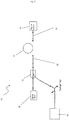
- Figure 3 illustrates an apparatus 50 used by the applicant to test the effects of ionization on the first optical fiber 11 of the apparatus of Figure 1 .
- the various embodiments of this fiber 11 described above have each been tested by the applicant.
- a gamma source 18 was used to simulate the effects of ionization, which are overwhelmingly responsible for radiation induced attenuation (RIA).
- RIA radiation induced attenuation
- the non-ionizing effects, such as lattice displacement, were not simulated but a consensus across the industry demonstrates that using a gamma radiation source to simulate the SEP flux is acceptable.
- 100m lengths of fiber 11 was irradiated passively (without light or pump passing through) using a Co60 source for a period of four hours at a dose rate of 50Gy/hr, confirmed by national standards.
- the total dose was therefore 200Gy, which is equivalent to 146% the total radiation dose in a 20 year mission lifetime in geostationary earth orbit (GEO).
- the radiation level tolerance was ⁇ 10% and the temperature was maintained between 23 and 25 °C.
- a 100 meter length of each fiber 11 was kept as a control.
- the fiber attenuation i.e. optical loss
- a PK2500 system across the wavelengths of interest, before and after radiation.
- RIA was calculated by subtracting the unradiated attenuation values from the post radiated value at each wavelength.
- the fiber was left for a year to thermally anneal at room temperature; it is assumed that all appreciable thermal annealing would have occurred in this time period.
- Photo annealing was subsequently performed using the optical pump 14 at 974nm at 175mW (measured at the amplifying fiber) with seeds 19 at 1536.61nm, 1541.35nm, 1550.92nm and 1552.52nm.
- the length of the fiber 11 used was varied as a function of the absorption per meter at 1531nm so that the total absorption over the full length was constant at 80dB for each sample tested.
- the fiber 11 was pumped continuously at 974nm for several days and the output power was measured at regular intervals by a power meter 20.
- the output power was extrapolated to 20 years using a power curve fit, in keeping with kinetic models of radiation damage such as those discussed by D.L. Griscom, M.E. Gingerich and E.J. Friebele in "Model for the dose, dose rate, and temperature dependence of radiation-induced loss in optical fibers” (IEEE TRANS.NUCL. SCI., VOL. 41, pp. 523-527, 1994 ) and G. M. Williams and E. J. Frieble in "Space radiation effects on erbium doped fiber devices: sources, amplifiers, and passive measurements” (IEEE Trans. Nucl. Sci., vol. 45, pp. 1531-1536, June 1998 ).
- a satellite or spacecraft optical transmission apparatus in accordance with the present invention 10 shows excellent recovery from radiation damage and is likely to withstand a 20 year mission lifetime. It is believed by the applicants that the recovery mechanism is the annealing of point defects associated with trivalent materials under pumping of 980 nm.
- an optical fiber doped with lanthanum such as fiber A
- fiber A show rapid recovery despite suffering substantial initial radiation damage.
- fibers are suitable for use in high radiation environments such as space over prolonged periods.
- such fibers are best suited to applications where the pump will be active for more than 20% of the mission lifetime.
- an optical fiber without lanthanum doping, such as fiber B is more resistant to initial damage but demonstrates a slower rate of recovery. Accordingly, such fibers are optimal for use for less than 20% of a 20 year mission lifetime.
- the high radiation environment is an extraterrestrial environment such as a low Earth orbit (LEO).
- the high radiation environment may be within a nuclear reactor facility, for example.
- the method in accordance with the invention comprises providing, to a high radiation environment, an optical fiber comprising erbium as an active trivalent dopant and at least aluminum and lanthanum as passive trivalent dopants at step 101.
- the optical fiber may be as hereinbefore described in relation to the apparatus illustrated in Figure 1 .
- the core may be formed of silica doped with erbium, lanthanum, aluminum and trivalent germanium in the following doping densities: Erbium: 370 parts per million (ppm) Lanthanum: between 10,000 and 20,000 ppm Aluminum: between 35,000 and 50,000 ppm Germanium: 10,000 ppm
- the core may comprise doping as described in the alternative embodiments above.
- the method comprises providing, to a high radiation environment, an optical pump source configured to provide an output at approximately 980 nm, for example the optical pump source 14 illustrated in the assembly 10 of figure 1 .
- the method further comprises, at step 103, transmitting a signal along the optical fiber in a high radiation environment.
- the signal is amplified during its transmission.
- the signal may, for example, be a communications signal within an intra-satellite data transfer system.
- the method further comprises pumping the optical fiber at a wavelength of approximately 980nm at step 104, this step preferably being performed in the high radiation environment.
- the method may also comprise creating multiple passes through a fiber laser cavity.
- the apparatus 60 for use with this method is illustrated in Figure 5 .
- the cavity is defined between two reflective or partially reflective surfaces such as mirrors 21a, 21b.
- the reflective mechanism may be in the form of Bragg gratings.
- a length of optical fiber 11 extends between the two mirrors 21a, 21b.
- the core of the optical fiber 11 in accordance with the invention comprises as an active trivalent dopant erbium and as passive trivalent dopants lanthanum and aluminum.
- the optical fiber 11 may be as hereinbefore described in relation to the apparatus illustrated in Figure 1 .
- Second and third optical fibers 12, 13 in an embodiment are optically coupled to the first optical fiber 11 at respective longitudinal ends thereof.
- the second and third optical fibers 12, 13 may be as hereinbefore described in relation to the apparatus illustrated in Figure 1 .
- the second and third optical fibers 12, 13 may be identical to the first optical fiber 11 such that the apparatus 60 comprises only one optical fiber.
- the apparatus of Figure 5 illustrates a free space set up and includes lenses 22a, 22b and 22c for focusing and collimating.
- An optical pump source 14 is configured to pump the optical fiber 11 12, 13 at approximately 980nm.
- the fiber composition may be from any source and may be delivered at a constant dose rate or pulsed. All such variations and modifications are intended to be included within the scope of the appended claims.
- the optical transmission apparatus may be included within a steering or other control system for a spacecraft or satellite.
Landscapes
- Physics & Mathematics (AREA)
- Electromagnetism (AREA)
- Engineering & Computer Science (AREA)
- Optics & Photonics (AREA)
- Plasma & Fusion (AREA)
- Chemical & Material Sciences (AREA)
- Signal Processing (AREA)
- Computer Networks & Wireless Communication (AREA)
- Astronomy & Astrophysics (AREA)
- General Physics & Mathematics (AREA)
- Life Sciences & Earth Sciences (AREA)
- Chemical Kinetics & Catalysis (AREA)
- General Chemical & Material Sciences (AREA)
- Geochemistry & Mineralogy (AREA)
- Materials Engineering (AREA)
- Organic Chemistry (AREA)
- Lasers (AREA)
Description
- The present invention relates to transmission via optical fibers in satellites and spacecraft and other high radiation environments.
- The Sun emits hazardous radiation in the form of SPEs (Solar Particle Events). These charged and highly energetic particles can interact with materials and cause: lattice deformation via ionization (both directly and indirectly); lattice deformation by direct collision; impurity creation in the lattice by neutron capture (neutrons produced in primary interactions); energy deposition which can lead to build up of charge, thus distorting the lattice. In addition to SPEs, there are also Galactic Cosmic Rays (GCR), energetic charged particles from Deep Space. These are less apparent because the solar activity deflects the GCR. Occasionally, the Sun emits a coronal mass ejection (CME) which is seen alongside a solar flare. CMEs release a much greater flux of SPEs and have been known to cause mission failure in satellites or spacecraft.
- On Earth, the magnetosphere provides protection from the harmful radiation from the Sun and Deep Space by deflecting the majority of high energy particles. In addition, the atmosphere attenuates the energetic particles that do pass through the magnetosphere. However, when in orbit around the Earth, this protection is diminished due to lack of atmosphere and weakening of the magnetosphere with distance from the Earth's core. It is particularly harmful to have the satellites orbiting within the radii of the Van Allen belts due to their nature as regions of trapped electrons and protons within the inner magnetosphere, between 60 and 6000 miles altitude for the inner belt and between 8,400 to 36,000miles for the outer belt. These radii vary with solar activity, so specific orbital tracks must be considered. Different elevation orbits have different associated dose rates, resulting in different total doses depending on the mission lifetime. A higher total dose is more harmful to both humans and equipment. It is also believed that a higher dose rate can have a more detrimental effect. In a geostationary orbit for 20 years, the expected total dose is 137Gy from behind 10mm thick aluminum shielding. In low earth orbit (LEO) the dose is less than half this value.
- Both SPE and GCR lead to distortions in the lattice of a material and have specific effects on different types of materials. In optical materials, this can lead to defect creation via the previously mentioned processes in the fiber lattice structure. Not only is there creation of new defects, but intrinsic defects are also exacerbated. The radiation induced defects will absorb light, so that less light can propagate the fiber, resulting in so-called radiation induced attenuation (RIA). In order to keep the fiber as radiation tolerant as possible, it is therefore important to keep as perfect a lattice structure as possible.
- It has previously been reported that a full recovery from radiation damage to optical fibers can be found from pumping at both 980nm and 532nm. It is, however, not ideal in space to have multiple pumps since this requires more mass, power and adds another layer of complexity in reliability testing.
- It will be appreciated that the opportunities to repair or replace optical fibers located on satellites or spacecraft are very limited. Even if repair or replacement is possible, it is typically a very expensive process.
- Furthermore, given the use typical applications of optical fibers within satellites and/or spacecraft, any damage thereto could have very serious implications. For example, the optical fibers may be utilized within a spacecraft's navigation system, and hence any damage thereto may cause the spacecraft to take an incorrect path.
- It is therefore essential to ensure that optical fibers used on satellites and spacecraft are optimally resistant to damage, particularly radiation damage.
-
US2012/0134376 A1 discloses a radiation-insensitive erbium doped amplifying optical fiber pumped at 980nm, with a central core formed of a core matrix and nanoparticles, wherein the nanoparticles are formed of a nanoparticle matrix surrounding the erbium. The nano-particle matrix may include complementary dopants such as aluminum and/or lanthanum. - Todd S Rose ET AL: "Gamma and Proton Radiation Effects in Erbium-Doped Fiber Amplifiers: Active and Passive Measurements", JOURNAL OF LIGHTWAVE TECHNOLOGY, IEEE SERVICE CENTER, NEW YORK, NY, US, vol. 19, no. 12, December 2001, evaluates the relative radiation sensitivity of commercially available Er-doped fibers configured as optical amplifiers using 980nm pump signals.
- Tz-Shiuan Peng ET AL: "Photo-annealing effects for erbium doped fiber sources after gamma irradiation tests by using 532 nm and 976 nm lasers", Proceedings of SPIE, vol. 7503, 5 October 2009, pages 750375-750375-4, investigates two EDFs with different sensitivites to radiation, by comparing photo-annealing efficiencies obtained by using 532nm and 976nm pump lasers. One EDF has an Er3+concentration of approximately 299ppm, and is co-doped with Al and La.
- As used herein, "optical" includes all forms of electromagnetic radiation, whether visible or invisible to the human eye.
- As used herein, "extraterrestrial location" is any location outside of the Earth's atmosphere. Examples of extraterrestrial locations include a low earth orbit (LEO) such as that of the International Space Station (ISS), a medium earth orbit (MEO), a geostationary earth orbit (GEO) and a geostationary transfer orbit (GTO).
- As used herein, "high radiation environment" is an environment in which the average radiation dose is greater than approximately 1 × 10⁻⁵ Gy/h.
- As used herein, an "active dopant" is a dopant which, when optically pumped, absorbs the pump photons and uses the absorbed energy to amplify the seed or signal transmitted by the optical fiber.
- As used herein, a "passive dopant" is a dopant that, when pumped, does not substantially absorb the pump photons. A passive dopant may, however, modify the optical properties of the optical fiber through modifications of the structure thereof.
- In accordance with the present invention, as seen from a first aspect, there is provided a spacecraft or satellite optical transmission apparatus in accordance with claim 1.
- It has been found by the applicant that an optical transmission system in accordance with the present invention demonstrates effective recovery from radiation induced attenuation (RIA). This is contrary to established thinking, which suggests that co-doping an active trivalent dopant with a passive trivalent dopant, particularly in high concentrations, produces an optical fiber with poor performance under radiation. Established thinking, in particular, suggests that co-doping an active trivalent dopant with aluminum produces an optical fiber that demonstrates greatly increased losses under high radiation conditions. It has been found by the applicant that optical pumping reverses this trend, which is believed to be due to the annealing of point defects associated with trivalent materials under such pumping.
- The doping density of the passive trivalent dopants may be varied according to the doping density of the active trivalent dopant. Preferably the ratio of doping densities of passive trivalent dopants to active trivalent dopants is between approximately 20 and approximately 180 to 1.
- The active trivalent dopant and passive trivalent dopants are preferably arranged in a trivalent matrix.
- The optical fiber preferably comprises a single active trivalent dopant, but may comprise additional active trivalent dopants.
- In accordance with the invention the active trivalent dopant is erbium. As will be appreciated by a person skilled in the art, erbium is a trivalent material, but its concentration is fixed by the amount of absorption that is required of the fiber. Erbium constitutes the active component of the fiber, which absorbs the pump photons and uses that energy to amplify a signal carried by the fiber. The erbium doping concentration is therefore varied according to the absorption required for the particular application.
- Erbium is provided at a doping density of between approximately 100 parts per million (ppm) and approximately 3000 ppm.
- Preferably the one or more passive trivalent dopants are selected from the group consisting of: lanthanum; aluminum; and phosphorus.
- As set out above co-doping with passive trivalent materials such as aluminium is thought to greatly increase radiation induced attenuation (RIA), which is undesirable. In the case without radiation induced attenuation though the addition of aluminium acts to improve the spectral gain flatness and increase the overall usable spectral bandwidth of a fiber in a fiber amplifier. The addition of aluminium is also beneficial for the incorporation of a higher concentration of erbium and reduces unwanted erbium ion clustering which can improve the amplifier efficiency.
- In accordance with the invention the two or more passive trivalent dopants comprise aluminum and lanthanum.
- The passive trivalent dopants may comprise a member of the lanthanide series of chemical elements.
- The passive trivalent dopants comprise lanthanum, which is provided at a dopant density between approximately 10,000 ppm and approximately 120,000 ppm. It has been found by the applicant that the presence of lanthanum in an optical fiber provides an improved recovery during anneal.
- Additionally the passive trivalent dopants comprise trivalent aluminum, provided at a doping density of between approximately 10,000 ppm and 60,000 ppm.
- Additionally the passive trivalent dopants may comprise phosphorus, which may be provided at a doping density of up to approximately 20,000 ppm.
- The active trivalent dopants and the passive trivalent dopants are preferably disposed within a core of the optical fiber.
- The optical fiber, preferably the core thereof, may comprise silica, which preferably defines a base material.
- The optical fiber, preferably the core thereof, may comprise germanium. Preferably the optical fiber, and more preferably the core thereof, comprises germanosilicate, which preferably defines a base material.
- The core of the optical fiber preferably comprises a diameter of between approximately 2 µm and approximately 20 µm. More preferably, the core of the optical fiber comprises a diameter of between approximately 2 µm and approximately 7 µm.
- The optical fiber preferably comprises a cladding layer that circumferentially surrounds the core. Preferably the cladding layer comprises a diameter of between approximately 60 µm and approximately 200 µm. More preferably, the cladding layer comprises a diameter of between approximately 120 µm and approximately 130 µm. Preferably of the optical fiber comprises an outer dual coating of acrylate.
- The apparatus is configured for optically pumping the optical fiber at a single wavelength only. In this regard, the apparatus comprises exactly one optical pump source configured for optically pumping at least a portion of the optical fiber.
- It has been found by the applicant that an optical fiber comprising a passive trivalent dopant shows excellent recovery under optical annealing at a single pump wavelength. The present invention therefore obviates the requirement for multiple pumps and consequently permits reduction in the mass and complexity of the optical transmission apparatus. It will be appreciated that mass budgeting is vital to any space mission; an estimate from 2004 provided in "Spacecraft Systems Engineering" (Third Edition) gives a cost of $25,000 per kilogram of mass launched into space. Preferably the optical pump source comprises a laser source.
- The optical pump is configured to provide pump energy having a wavelength of between approximately 970 nm and approximately 990 nm. Whilst current space technology uses 1480 nm pumps, it has been found by the applicants that such pumps would not be particularly effective in annealing radiation induced damage.
- Advantageously the pumping of the optical fiber at around 980nm has been seen to reverse the trend of RIA in fibers containing trivalent materials such as aluminium or lanthanum. Also, it follows that the benefits of co-doping with these trivalent materials can now be achieved in high radiation environments. Therefore the fiber and apparatus described may provide superior gain flatness and maintain a wide spectral bandwidth in a high radiation environment for the lifetime of operation. This means that advantageously, the spectral performance of the fiber is maintained.
- In a preferred embodiment, the optical transmission apparatus comprises an optical amplifier.
- The optical amplifier may be included within a spacecraft or satellite data communications system, which may be arranged for internal or external communications.
- In one embodiment, the optical transmission apparatus defines part of a fiber optic gyroscope, which may constitute part of a navigation system of the spacecraft or satellite. The optical transmission apparatus preferably defines an optical source of the fiber optic gyroscope. In use, a pulse of radiation from the optical source, is split by an optical splitter, the two pulses being injected into a closed loop or closed series of loops of optical fiber in different directions. If the fiber optic gyroscope is subjected to rotation in the plane of the loop or loops, the beam travelling against the rotation experiences a marginally shorter path delay than the other beam.
- In accordance with the present invention, also as seen from a first aspect, there is provided a spacecraft or satellite comprising an optical transmission apparatus as hereinbefore described.
- In accordance with the present invention, as seen from a second aspect, there is provided a method for transmitting electromagnetic radiation via an optical fiber in a high radiation environment, in accordance with
claim 10. - The high radiation environment may be an extraterrestrial environment, which includes but is not limited to a low earth orbit (LEO), medium earth orbit (MEO), geostationary earth orbit (GEO) or geostationary transfer orbit (GTO).
- Alternatively or additionally, the high radiation environment may be within or proximal to a nuclear reactor facility.
- Alternatively or additionally, the high radiation environment may be within or proximal to high energy physics (HEP) apparatus such as a particle collider.
- Alternatively or additionally, the high radiation environment may be within radiation sensing apparatus.
- Preferably the optical fiber comprises one or more of the above-mentioned features.
- Preferably the optical pump source comprises one or more of the above-mentioned features.
- Preferably the method comprises optically pumping the optical fiber with radiation from the optical pump source.
- In accordance with the present invention, as seen from a third aspect, there is provided a radiation insensitive fiber laser cavity.
- An embodiment of the present invention will now be described by way of example only and with reference to the accompanying drawings, in which:
-
Figure 1 is a schematic illustration of an optical transmission apparatus within a satellite or spacecraft in accordance with an embodiment of the present invention as seen from the first aspect; -
Figure 2 is a flow diagram of a method for transmitting electromagnetic radiation via an optical fiber in a high radiation environment in accordance with an embodiment of the present invention as seen from the second aspect; -
Figure 3 is a schematic illustration of an apparatus used for testing the optical transmission apparatus illustrated inFigure 1 ; -
Figure 4 is a table of results of the testing illustrated inFigure 1 ; and -
Figure 5 is a schematic illustration of an optical transmission apparatus ofFigure 1 , in accordance with an alternative embodiment of the present invention as seen from the first aspect. - Referring to
Figure 1 of the drawings, there is illustrated anoptical transmission apparatus 10 of a satellite or spacecraft. In the illustrated embodiment, theoptical transmission apparatus 10 is in the form of an erbium doped fiber amplifier (EDFA) within a satellite communications system. - The
apparatus 10 comprises a firstoptical fiber 11 and second and thirdoptical fibers optical fiber 11. The first, second and thirdoptical fibers second fiber 12, through thefirst fiber 11 and subsequently through the third fiber. - The
first fiber 11 comprises a central doped core between 3 and 20µm in diameter, surrounded by 125µm diameter cladding of pure silica. Thefiber 11 may be further coated, for example in dual acrylate. - The core of the first
optical fiber 11 is formed of germanosilicate doped with erbium, lanthanum and aluminum in the following doping densities (subject to +/- 20%):Erbium: 370 parts per million (ppm) Lanthanum: between 10,000 and 20,000 ppm Aluminum: between 35,000 and 60,000 ppm - As will be appreciated by a person skilled in the art, erbium is an active trivalent dopant, whereas lanthanum and aluminum are passive trivalent dopants. The active trivalent dopant concentration, namely the erbium concentration, is fixed by the level of absorption required for the particular application but this is not the case for the passive trivalent dopants.
- The second and third
optical fibers third fibers optical fibers - The
apparatus 10 further comprises anoptical pump source 14 in the form of a 980nm laser source. - The fiber could be used as an ASE source, amending
apparatus 10 by removing the signal input and pumping the fiber with no seed source. - A wavelength division multiplexing (WDM)
coupler 15 is configured to couple asignal 16 to be amplified by theapparatus 10 with the output from theoptical pump source 14. TheWDM coupler 15 is located at a longitudinal end of the secondoptical fiber 12 distal to the firstoptical fiber 11. - In use, the doping in the first
optical fiber 11 facilitates optical amplification: this is achieved by stimulated emission of photons from dopant ions in the core offiber 11. In detail, the radiation from thelaser source 14 excites the dopant ions into a higher energy level. Once in this higher energy level, the ions decay back to a lower energy level through stimulated emission of a photon at the signal wavelength, thereby amplifying the signal. - The
first fiber 11 in the above-described embodiment will henceforth be referred to as fiber A. - In an alternative embodiment, the core of the first
optical fiber 11 is formed of germanosilicate doped with erbium, lanthanum and aluminum the following doping densities (subject to +/- 20%):Erbium: 1200 ppm Lanthanum: between 20,000 and 30,000 ppm Aluminum: between 35,000 and 60,000 ppm - In another alternative embodiment, the core of the first
optical fiber 11 is formed of germanosilicate doped with erbium, lanthanum and aluminum in the following doping densities (subject to +/- 20%):Erbium: 1700 ppm Lanthanum: between 80,000 and 120,000 ppm Aluminum: between 35,000 and 60,000 ppm - In another alternative embodiment, the core of the first
optical fiber 11 is formed of germanosilicate doped with erbium and aluminum in the following doping densities (subject to +/- 20%):Erbium: 1100 ppm Lanthanum: between 10,000 and 20,000 ppm Aluminum: between 35,000 and 60,000 ppm - In yet another alternative embodiment, the core of the first
optical fiber 11 is formed of silica doped with erbium, aluminum and germanium in the following doping densities (subject to +/- 20%):Erbium: 2600 ppm Lanthanum: between 10,000 and 20,000 ppm Aluminum: between 35,000 and 60,000 ppm - In certain examples not in accordance with the invention the core of the first
optical fiber 11 may be doped with erbium and aluminum but not with lanthanum. - In one example not in accordance with the invention, herein fiber B, the core of the first
optical fiber 11 is formed of silica doped with erbium and aluminum in the following doping densities (subject to +/- 20%):Erbium: 380 ppm Aluminum: between 20,000 and 40,000 ppm - In another alternative example not in accordance with the invention, herein fiber C, the core of the first
optical fiber 11 is formed of germanosilicate doped with erbium and aluminum in the following doping densities (subject to +/- 20%):Erbium: 450 ppm Aluminum: between 35,000 and 60,000 ppm -
Figure 3 illustrates anapparatus 50 used by the applicant to test the effects of ionization on the firstoptical fiber 11 of the apparatus ofFigure 1 . The various embodiments of thisfiber 11 described above have each been tested by the applicant. - A
gamma source 18 was used to simulate the effects of ionization, which are overwhelmingly responsible for radiation induced attenuation (RIA). The non-ionizing effects, such as lattice displacement, were not simulated but a consensus across the industry demonstrates that using a gamma radiation source to simulate the SEP flux is acceptable. - 100m lengths of
fiber 11 was irradiated passively (without light or pump passing through) using a Co60 source for a period of four hours at a dose rate of 50Gy/hr, confirmed by national standards. The total dose was therefore 200Gy, which is equivalent to 146% the total radiation dose in a 20 year mission lifetime in geostationary earth orbit (GEO). The radiation level tolerance was ± 10% and the temperature was maintained between 23 and 25 °C. A 100 meter length of eachfiber 11 was kept as a control. - The fiber attenuation, i.e. optical loss, was tested with a PK2500 system across the wavelengths of interest, before and after radiation. RIA was calculated by subtracting the unradiated attenuation values from the post radiated value at each wavelength. The fiber was left for a year to thermally anneal at room temperature; it is assumed that all appreciable thermal annealing would have occurred in this time period.
- Photo annealing was subsequently performed using the
optical pump 14 at 974nm at 175mW (measured at the amplifying fiber) withseeds 19 at 1536.61nm, 1541.35nm, 1550.92nm and 1552.52nm. The length of thefiber 11 used was varied as a function of the absorption per meter at 1531nm so that the total absorption over the full length was constant at 80dB for each sample tested. Thefiber 11 was pumped continuously at 974nm for several days and the output power was measured at regular intervals by apower meter 20. - As will be appreciated by a person skilled in the art, radiating the
fiber 11 at a high dose rate for a short amount of time then following with annealing is not identical treatment to simultaneously irradiating the fiber and photo-annealing, as would occur under continuous use in Earth orbit or other space applications. Instead, giving the total dosage in a short amount of time and then annealing thefiber 11 simulates a worst case scenario, since all of the damage requires healing. Furthermore, research within the industry reveals that the same total dose provided as a higher dose rate produces more damage than a lower dose rate for a longer period. - The output power was extrapolated to 20 years using a power curve fit, in keeping with kinetic models of radiation damage such as those discussed by D.L. Griscom, M.E. Gingerich and E.J. Friebele in "Model for the dose, dose rate, and temperature dependence of radiation-induced loss in optical fibers" (IEEE TRANS.NUCL. SCI., VOL. 41, pp. 523-527, 1994) and G. M. Williams and E. J. Frieble in "Space radiation effects on erbium doped fiber devices: sources, amplifiers, and passive measurements" (IEEE Trans. Nucl. Sci., vol. 45, pp. 1531-1536, June 1998).
- The percentage recovery was found by calculating the extrapolated final output as a percentage of the control fiber output. The results for fibers A, B and C may be seen in
Figure 4 . It will be appreciated that fiber A cannot recover to above 100%; the figure of 100.63% is due to a small standard error within the experimental process. - Testing as described above has demonstrated that a satellite or spacecraft optical transmission apparatus in accordance with the
present invention 10 shows excellent recovery from radiation damage and is likely to withstand a 20 year mission lifetime. It is believed by the applicants that the recovery mechanism is the annealing of point defects associated with trivalent materials under pumping of 980 nm. - Furthermore, it can be seen from the results of such tests that an optical fiber doped with lanthanum, such as fiber A, show rapid recovery despite suffering substantial initial radiation damage. Accordingly, such fibers are suitable for use in high radiation environments such as space over prolonged periods. In particular, such fibers are best suited to applications where the pump will be active for more than 20% of the mission lifetime. On the other hand, an optical fiber without lanthanum doping, such as fiber B, is more resistant to initial damage but demonstrates a slower rate of recovery. Accordingly, such fibers are optimal for use for less than 20% of a 20 year mission lifetime.
- With reference to
Figure 2 of the drawings, there is illustrated amethod 100 for transmitting electromagnetic radiation via an optical fiber in a high radiation environment in accordance with an embodiment of the present invention. - In the illustrated embodiment, the high radiation environment is an extraterrestrial environment such as a low Earth orbit (LEO). Alternatively, the high radiation environment may be within a nuclear reactor facility, for example.
- The method in accordance with the invention comprises providing, to a high radiation environment, an optical fiber comprising erbium as an active trivalent dopant and at least aluminum and lanthanum as passive trivalent dopants at
step 101. The optical fiber may be as hereinbefore described in relation to the apparatus illustrated inFigure 1 . For example, the core may be formed of silica doped with erbium, lanthanum, aluminum and trivalent germanium in the following doping densities:Erbium: 370 parts per million (ppm) Lanthanum: between 10,000 and 20,000 ppm Aluminum: between 35,000 and 50,000 ppm Germanium: 10,000 ppm - Alternatively, the core may comprise doping as described in the alternative embodiments above.
- At
step 102, the method comprises providing, to a high radiation environment, an optical pump source configured to provide an output at approximately 980 nm, for example theoptical pump source 14 illustrated in theassembly 10 offigure 1 . - The method further comprises, at
step 103, transmitting a signal along the optical fiber in a high radiation environment. The signal is amplified during its transmission. The signal may, for example, be a communications signal within an intra-satellite data transfer system. - The method further comprises pumping the optical fiber at a wavelength of approximately 980nm at
step 104, this step preferably being performed in the high radiation environment. - The method may also comprise creating multiple passes through a fiber laser cavity.
- The
apparatus 60 for use with this method is illustrated inFigure 5 . The cavity is defined between two reflective or partially reflective surfaces such asmirrors - A length of
optical fiber 11 extends between the twomirrors optical fiber 11 in accordance with the invention comprises as an active trivalent dopant erbium and as passive trivalent dopants lanthanum and aluminum. Theoptical fiber 11 may be as hereinbefore described in relation to the apparatus illustrated inFigure 1 . - Second and third
optical fibers optical fiber 11 at respective longitudinal ends thereof. The second and thirdoptical fibers Figure 1 . Alternatively, the second and thirdoptical fibers optical fiber 11 such that theapparatus 60 comprises only one optical fiber. The apparatus ofFigure 5 illustrates a free space set up and includeslenses - An
optical pump source 14 is configured to pump theoptical fiber 11 12, 13 at approximately 980nm. - Various modifications may be made to the described embodiments of apparatus and method without departing from the scope of the present invention. For example other dopants in addition to erbium, such as thulium, ytterbium, holium and/or neodymium could be included in the fiber composition. The radiation may be from any source and may be delivered at a constant dose rate or pulsed. All such variations and modifications are intended to be included within the scope of the appended claims. For example the optical transmission apparatus may be included within a steering or other control system for a spacecraft or satellite.
Claims (15)
- A spacecraft or satellite optical transmission apparatus (10) comprising:an optical fiber (11, 12, 13) comprising an active trivalent dopant and at least two passive trivalent dopants wherein in use the optical fiber having recovery from radiation induced attenuation; anda single optical pump source (14) operatively coupled to provide photoannealing pump energy to the optical fiber; whereinthe active trivalent dopant is erbium at a doping density of between approximately 100 ppm and approximately 3,000 ppm andone of the passive trivalent dopants is La at a dopant density of between approximately 10,000 and approximately 120,000 ppm and another of the passive trivalent dopants is trivalent aluminum at a doping density of between approximately 10,000 ppm and 60,000 ppm, preferably 35,000 and 60,000 ppm; wherein the optical pump is configured to provide pump energy having a wavelength of between approximately 970 nm and approximately 990 nm; and further wherein the apparatus is configured for optically pumping the optical fiber at a single wavelength only for recovery from radiation induced attenuation.
- A spacecraft or satellite optical transmission apparatus (10) according to claim 1, wherein the passive trivalent dopants further comprise phosphorus.
- A spacecraft or satellite optical transmission apparatus (10) according to claim 1 or claim 2, wherein the active trivalent dopant and at least one passive trivalent dopant form a trivalent matrix.
- A spacecraft or satellite optical transmission apparatus (10) according to claim 1, claim 2 or claim 3, wherein the active trivalent dopant and the une passive trivalent dopants are within a core of the optical fiber.
- A spacecraft or satellite optical transmission apparatus (10) according to any one of claims 1 to 4, wherein the optical transmission apparatus (10) comprises one or more of an optical amplifier, an amplified spontaneous emission (ASE) source and a fiber laser, and/or forms part of a spacecraft or satellite data communications system.
- A spacecraft or satellite optical transmission apparatus (10) according to any one of claims 1 to 5, wherein the optical transmission apparatus (10) defines part of a fiber optic gyroscope.
- A spacecraft or satellite optical transmission apparatus (10) according to any one of the preceding claims, wherein the La is at a dopant density of between approximately 10,000 and approximately 20,000 ppm; or between approximately 20,000 and approximately 30,000 ppm.
- A spacecraft or satellite optical transmission apparatus (10) according to any one of claims 1 to 6, wherein the La is at a dopant density of between approximately 80,000 and approximately 120,000 ppm.
- A spacecraft or satellite comprising an optical transmission apparatus (10) according to any one of claims 1 to 8.
- A method for transmitting electromagnetic radiation via an optical fiber in a high radiation environment in which the average radiation dose is greater than approximately 1 × 10⁻⁵ Gy/h, and in which there is used:an optical fiber (11, 12, 13) comprising an active trivalent dopant and at least two passive trivalent dopants wherein in use the optical fiber having recovery from radiation induced attenuation; and,a single optical pump source (14) operatively coupled to provide photoannealing pump energy to the optical fiber; whereby the active trivalent dopant is erbium, one of the passive trivalent dopants is La, and another of the passive trivalent dopants is aluminum;wherein the ratio of doping density measured in ppm of passive trivalent dopants to active trivalent dopants is 20:1 to 180:1; wherein the erbium is at a doping density of between approximately 100 ppm and approximately 3,000 ppm, the La is at a dopant density of between approximately 10,000 and approximately 120,000 ppm and the aluminum is at a doping density of between approximately 10,000 ppm and 60,000 ppm, and wherein the optical pump is configured to provide pump energy having a wavelength of between approximately 970 nm and approximately 990 nm; and further wherein the optical pump source is configured for optically pumping the optical fiber at a single wavelength only for recovery from radiation induced attenuation.
- A method according to claim 10, wherein the high radiation environment is an extraterrestrial environment, or is within or proximal to a nuclear reactor facility, or is within or proximal to high energy physics, HEP, apparatus.
- A method according to claim 10 or claim 11, wherein the trivalent aluminum is at a doping density of between approximately 35,000 and 60,000 ppm.
- A method according to claim 10, claim 11 or claim 12, wherein the La is at a dopant density of between approximately 10,000 and approximately 20,000 ppm.
- A method according to claim 10, claim 11 or claim 12, wherein the La is at a dopant density of between approximately 20,000 and approximately 30,000 ppm.
- A method according to claim 10, claim 11 or claim 12, wherein the La is at a dopant density of between approximately 80,000 and approximately 120,000 ppm.
Applications Claiming Priority (1)
| Application Number | Priority Date | Filing Date | Title |
|---|---|---|---|
| GB1321845.8A GB2521156A (en) | 2013-12-10 | 2013-12-10 | Optical transmission |
Publications (3)
| Publication Number | Publication Date |
|---|---|
| EP2884603A2 EP2884603A2 (en) | 2015-06-17 |
| EP2884603A3 EP2884603A3 (en) | 2015-09-02 |
| EP2884603B1 true EP2884603B1 (en) | 2021-10-06 |
Family
ID=50000501
Family Applications (1)
| Application Number | Title | Priority Date | Filing Date |
|---|---|---|---|
| EP14197127.5A Active EP2884603B1 (en) | 2013-12-10 | 2014-12-10 | Optical transmission |
Country Status (4)
| Country | Link |
|---|---|
| US (1) | US9515732B2 (en) |
| EP (1) | EP2884603B1 (en) |
| ES (1) | ES2903372T3 (en) |
| GB (1) | GB2521156A (en) |
Families Citing this family (2)
| Publication number | Priority date | Publication date | Assignee | Title |
|---|---|---|---|---|
| US10177523B2 (en) * | 2015-09-14 | 2019-01-08 | National Applied Research Laboratories | Recovering a rare-earth-doped optical fiber under irradiation |
| US12580359B2 (en) * | 2022-04-18 | 2026-03-17 | Corning Incorporated | Amplifying optical fibers |
Family Cites Families (13)
| Publication number | Priority date | Publication date | Assignee | Title |
|---|---|---|---|---|
| IT1237136B (en) * | 1989-10-30 | 1993-05-24 | Pirelli Cavi Spa | WIDE BANDWIDE SIGNAL WAVE LENGTH OPTICAL AMPLIFIER. |
| FR2714046B1 (en) * | 1993-12-16 | 1996-03-08 | France Telecom | Glass-ceramic materials, in particular for lasers and optical amplifiers doped with rare earths and process for manufacturing such materials. |
| GB2304978A (en) * | 1995-08-25 | 1997-03-26 | Univ Southampton | Optical waveguide, waveguide amplifier and laser |
| US7094361B2 (en) * | 1999-03-19 | 2006-08-22 | Rutgers, The State University | Optically transparent nanocomposite materials |
| US7725028B1 (en) * | 2001-07-30 | 2010-05-25 | At&T Intellectual Property I, Lp | Method for flexible multiple broadcast service delivery over a WDM passive optical network based on RF block-conversion of RF service bands with wavelength bands |
| US20030156318A1 (en) | 2001-12-31 | 2003-08-21 | Anderson Mark T. | Method for manufacturing silicate waveguide compositions for extended L-band and S-band amplification |
| US7724423B2 (en) * | 2006-03-16 | 2010-05-25 | Alcatel-Lucent Usa Inc. | Optical fiber laser having improved efficiency |
| DK2187486T3 (en) * | 2008-11-12 | 2014-07-07 | Draka Comteq Bv | Reinforcing optical fiber and method of manufacture |
| FR2939246B1 (en) | 2008-12-02 | 2010-12-24 | Draka Comteq France | AMPLIFIER OPTICAL FIBER AND METHOD OF MANUFACTURE |
| FR2939522B1 (en) | 2008-12-08 | 2011-02-11 | Draka Comteq France | OPTICAL FIBER AMPLIFIER RESISTANT TO IONIZING RADIATION |
| US9306363B1 (en) * | 2010-10-05 | 2016-04-05 | Stc.Unm | Active bidirectional mode-locked lasers and applications to accurate measurements in navigation systems |
| FR2968092B1 (en) | 2010-11-25 | 2012-12-14 | Draka Comteq France | DOPED OPTICAL FIBER IN RARE EARTHS THAT IS INSENSITIVE TO IRRADIATION |
| FR2968775B1 (en) * | 2010-12-10 | 2012-12-21 | Draka Comteq France | DOPED OPTICAL FIBER IN RARE EARTHS HAVING LOW INTERACTIONS BETWEEN THE DOPING ELEMENTS |
-
2013
- 2013-12-10 GB GB1321845.8A patent/GB2521156A/en not_active Withdrawn
-
2014
- 2014-12-09 US US14/564,619 patent/US9515732B2/en active Active
- 2014-12-10 ES ES14197127T patent/ES2903372T3/en active Active
- 2014-12-10 EP EP14197127.5A patent/EP2884603B1/en active Active
Non-Patent Citations (1)
| Title |
|---|
| TZ-SHIUAN PENG ET AL: "<title>Photo-annealing effects for erbium doped fiber sources after gamma irradiation tests by using 532 nm and 976 nm lasers</title>", PROCEEDINGS OF SPIE, vol. 7503, 5 October 2009 (2009-10-05), pages 750375 - 750375-4, XP055202044, ISSN: 0277-786X, DOI: 10.1117/12.835304 * |
Also Published As
| Publication number | Publication date |
|---|---|
| US9515732B2 (en) | 2016-12-06 |
| GB2521156A (en) | 2015-06-17 |
| GB201321845D0 (en) | 2014-01-22 |
| US20160164609A1 (en) | 2016-06-09 |
| EP2884603A2 (en) | 2015-06-17 |
| EP2884603A3 (en) | 2015-09-02 |
| ES2903372T3 (en) | 2022-04-01 |
Similar Documents
| Publication | Publication Date | Title |
|---|---|---|
| Berghmans et al. | An introduction to radiation effects on optical components and fiber optic sensors | |
| US9025925B2 (en) | Radiation-resistant rare-earth-doped optical fiber and method of radiation-hardening a rare-earth-doped optical fiber | |
| US9515732B2 (en) | Optical transmission | |
| Zhu et al. | Effect of Ce co-doping on radiation resistance behavior and laser performance of Er/Yb/Ce co-doped high-phosphorous polarization-maintaining silica fiber | |
| Haddad et al. | Comparison of gamma radiation effect on erbium doped fiber amplifiers | |
| Li et al. | Investigation of black box model for erbium-doped fiber amplifiers in space radiation environment | |
| Guangbiao et al. | Gamma Radiation-Induced Darkening Effect on Ytterbium-Doped Fiber Oscillators | |
| Yeniay et al. | Radiation induced loss properties and hardness enhancement technique for ErYb doped fibers for avionic applications | |
| Hill et al. | Fibercore AstroGain fiber: multichannel erbium doped fibers for optical space communications | |
| Friebele et al. | Erbium doped fibers for radiation tolerant, high power space laser communications | |
| Ladaci et al. | Optimization of rare-earth-doped amplifiers for space mission through a hardening-by-system strategy | |
| Meyer | Optical-fiber-based distributed dosimetry for space applications | |
| Facchini et al. | Investigation of the Radiation Response of a Dual-Stage Optical Amplifier | |
| Diep | 46 Sc Gamma-Ray Assembly for Studying Erbium and Erbium-Ytterbium Doped Optical Fibers for Space Applications | |
| Girard et al. | Radiation hardening techniques for rare-earth-based optical fibers and amplifiers | |
| Diep et al. | Review of gamma radiation effects on active EDF, EYDF with photobleaching and photoannealing | |
| Hill et al. | Fibers for multi-channel erbium doped amplifiers in optical space communications | |
| Hamdalla et al. | Radiation effects on the gain of thulium doped fiber amplifier: experiment and modeling | |
| Singleton | Radiation effects on ytterbium-doped optical fibers | |
| Girard et al. | Radiation effects on fiber amplifiers: design of radiation tolerant Yb/Er-based devices | |
| Facchini et al. | LED Lighting Influence on the Radiation Response of Erbium-Doped Fiber Amplifiers | |
| Girard et al. | Recent advances in radiation-hardened fiber-optic amplifiers for space-based laser communications | |
| Aubry | Coupled experimental and theoretical study of combined radiation and temperature effects on fiber-based amplifiers | |
| Osman et al. | Gamma radiation testing of reduced-clad Erbium-doped fibers and demonstration of an ultra-compact EDFA for satellite laser communications | |
| Poulin | Radiation Effects on an Active Ytterbium doped Fiber Laser |
Legal Events
| Date | Code | Title | Description |
|---|---|---|---|
| PUAI | Public reference made under article 153(3) epc to a published international application that has entered the european phase |
Free format text: ORIGINAL CODE: 0009012 |
|
| 17P | Request for examination filed |
Effective date: 20141210 |
|
| AK | Designated contracting states |
Kind code of ref document: A2 Designated state(s): AL AT BE BG CH CY CZ DE DK EE ES FI FR GB GR HR HU IE IS IT LI LT LU LV MC MK MT NL NO PL PT RO RS SE SI SK SM TR |
|
| AX | Request for extension of the european patent |
Extension state: BA ME |
|
| PUAL | Search report despatched |
Free format text: ORIGINAL CODE: 0009013 |
|
| AK | Designated contracting states |
Kind code of ref document: A3 Designated state(s): AL AT BE BG CH CY CZ DE DK EE ES FI FR GB GR HR HU IE IS IT LI LT LU LV MC MK MT NL NO PL PT RO RS SE SI SK SM TR |
|
| AX | Request for extension of the european patent |
Extension state: BA ME |
|
| RIC1 | Information provided on ipc code assigned before grant |
Ipc: H01S 3/16 20060101ALN20150724BHEP Ipc: G02B 6/02 20060101ALN20150724BHEP Ipc: H01S 3/067 20060101AFI20150724BHEP Ipc: H01S 3/00 20060101ALN20150724BHEP Ipc: H01S 3/094 20060101ALN20150724BHEP Ipc: H01S 3/17 20060101ALN20150724BHEP |
|
| R17P | Request for examination filed (corrected) |
Effective date: 20160302 |
|
| RBV | Designated contracting states (corrected) |
Designated state(s): AL AT BE BG CH CY CZ DE DK EE ES FI FR GB GR HR HU IE IS IT LI LT LU LV MC MK MT NL NO PL PT RO RS SE SI SK SM TR |
|
| STAA | Information on the status of an ep patent application or granted ep patent |
Free format text: STATUS: EXAMINATION IS IN PROGRESS |
|
| 17Q | First examination report despatched |
Effective date: 20180202 |
|
| GRAP | Despatch of communication of intention to grant a patent |
Free format text: ORIGINAL CODE: EPIDOSNIGR1 |
|
| STAA | Information on the status of an ep patent application or granted ep patent |
Free format text: STATUS: GRANT OF PATENT IS INTENDED |
|
| RIC1 | Information provided on ipc code assigned before grant |
Ipc: H01S 3/067 20060101AFI20210324BHEP Ipc: H01S 3/094 20060101ALN20210324BHEP Ipc: H01S 3/16 20060101ALN20210324BHEP Ipc: H01S 3/00 20060101ALN20210324BHEP Ipc: H01S 3/17 20060101ALN20210324BHEP Ipc: G02B 6/02 20060101ALN20210324BHEP |
|
| INTG | Intention to grant announced |
Effective date: 20210408 |
|
| GRAS | Grant fee paid |
Free format text: ORIGINAL CODE: EPIDOSNIGR3 |
|
| RAP3 | Party data changed (applicant data changed or rights of an application transferred) |
Owner name: FIBERCORE LIMITED |
|
| GRAA | (expected) grant |
Free format text: ORIGINAL CODE: 0009210 |
|
| STAA | Information on the status of an ep patent application or granted ep patent |
Free format text: STATUS: THE PATENT HAS BEEN GRANTED |
|
| RAP3 | Party data changed (applicant data changed or rights of an application transferred) |
Owner name: FIBERCORE LIMITED |
|
| AK | Designated contracting states |
Kind code of ref document: B1 Designated state(s): AL AT BE BG CH CY CZ DE DK EE ES FI FR GB GR HR HU IE IS IT LI LT LU LV MC MK MT NL NO PL PT RO RS SE SI SK SM TR |
|
| REG | Reference to a national code |
Ref country code: GB Ref legal event code: FG4D |
|
| REG | Reference to a national code |
Ref country code: CH Ref legal event code: EP Ref country code: AT Ref legal event code: REF Ref document number: 1437020 Country of ref document: AT Kind code of ref document: T Effective date: 20211015 |
|
| REG | Reference to a national code |
Ref country code: IE Ref legal event code: FG4D |
|
| REG | Reference to a national code |
Ref country code: DE Ref legal event code: R096 Ref document number: 602014080485 Country of ref document: DE |
|
| REG | Reference to a national code |
Ref country code: LT Ref legal event code: MG9D |
|
| REG | Reference to a national code |
Ref country code: NL Ref legal event code: MP Effective date: 20211006 |
|
| REG | Reference to a national code |
Ref country code: AT Ref legal event code: MK05 Ref document number: 1437020 Country of ref document: AT Kind code of ref document: T Effective date: 20211006 |
|
| REG | Reference to a national code |
Ref country code: ES Ref legal event code: FG2A Ref document number: 2903372 Country of ref document: ES Kind code of ref document: T3 Effective date: 20220401 |
|
| PG25 | Lapsed in a contracting state [announced via postgrant information from national office to epo] |
Ref country code: RS Free format text: LAPSE BECAUSE OF FAILURE TO SUBMIT A TRANSLATION OF THE DESCRIPTION OR TO PAY THE FEE WITHIN THE PRESCRIBED TIME-LIMIT Effective date: 20211006 Ref country code: LT Free format text: LAPSE BECAUSE OF FAILURE TO SUBMIT A TRANSLATION OF THE DESCRIPTION OR TO PAY THE FEE WITHIN THE PRESCRIBED TIME-LIMIT Effective date: 20211006 Ref country code: FI Free format text: LAPSE BECAUSE OF FAILURE TO SUBMIT A TRANSLATION OF THE DESCRIPTION OR TO PAY THE FEE WITHIN THE PRESCRIBED TIME-LIMIT Effective date: 20211006 Ref country code: BG Free format text: LAPSE BECAUSE OF FAILURE TO SUBMIT A TRANSLATION OF THE DESCRIPTION OR TO PAY THE FEE WITHIN THE PRESCRIBED TIME-LIMIT Effective date: 20220106 Ref country code: AT Free format text: LAPSE BECAUSE OF FAILURE TO SUBMIT A TRANSLATION OF THE DESCRIPTION OR TO PAY THE FEE WITHIN THE PRESCRIBED TIME-LIMIT Effective date: 20211006 |
|
| PG25 | Lapsed in a contracting state [announced via postgrant information from national office to epo] |
Ref country code: IS Free format text: LAPSE BECAUSE OF FAILURE TO SUBMIT A TRANSLATION OF THE DESCRIPTION OR TO PAY THE FEE WITHIN THE PRESCRIBED TIME-LIMIT Effective date: 20220206 Ref country code: SE Free format text: LAPSE BECAUSE OF FAILURE TO SUBMIT A TRANSLATION OF THE DESCRIPTION OR TO PAY THE FEE WITHIN THE PRESCRIBED TIME-LIMIT Effective date: 20211006 Ref country code: PT Free format text: LAPSE BECAUSE OF FAILURE TO SUBMIT A TRANSLATION OF THE DESCRIPTION OR TO PAY THE FEE WITHIN THE PRESCRIBED TIME-LIMIT Effective date: 20220207 Ref country code: PL Free format text: LAPSE BECAUSE OF FAILURE TO SUBMIT A TRANSLATION OF THE DESCRIPTION OR TO PAY THE FEE WITHIN THE PRESCRIBED TIME-LIMIT Effective date: 20211006 Ref country code: NO Free format text: LAPSE BECAUSE OF FAILURE TO SUBMIT A TRANSLATION OF THE DESCRIPTION OR TO PAY THE FEE WITHIN THE PRESCRIBED TIME-LIMIT Effective date: 20220106 Ref country code: NL Free format text: LAPSE BECAUSE OF FAILURE TO SUBMIT A TRANSLATION OF THE DESCRIPTION OR TO PAY THE FEE WITHIN THE PRESCRIBED TIME-LIMIT Effective date: 20211006 Ref country code: LV Free format text: LAPSE BECAUSE OF FAILURE TO SUBMIT A TRANSLATION OF THE DESCRIPTION OR TO PAY THE FEE WITHIN THE PRESCRIBED TIME-LIMIT Effective date: 20211006 Ref country code: HR Free format text: LAPSE BECAUSE OF FAILURE TO SUBMIT A TRANSLATION OF THE DESCRIPTION OR TO PAY THE FEE WITHIN THE PRESCRIBED TIME-LIMIT Effective date: 20211006 Ref country code: GR Free format text: LAPSE BECAUSE OF FAILURE TO SUBMIT A TRANSLATION OF THE DESCRIPTION OR TO PAY THE FEE WITHIN THE PRESCRIBED TIME-LIMIT Effective date: 20220107 |
|
| REG | Reference to a national code |
Ref country code: DE Ref legal event code: R097 Ref document number: 602014080485 Country of ref document: DE |
|
| PG25 | Lapsed in a contracting state [announced via postgrant information from national office to epo] |
Ref country code: SM Free format text: LAPSE BECAUSE OF FAILURE TO SUBMIT A TRANSLATION OF THE DESCRIPTION OR TO PAY THE FEE WITHIN THE PRESCRIBED TIME-LIMIT Effective date: 20211006 Ref country code: SK Free format text: LAPSE BECAUSE OF FAILURE TO SUBMIT A TRANSLATION OF THE DESCRIPTION OR TO PAY THE FEE WITHIN THE PRESCRIBED TIME-LIMIT Effective date: 20211006 Ref country code: RO Free format text: LAPSE BECAUSE OF FAILURE TO SUBMIT A TRANSLATION OF THE DESCRIPTION OR TO PAY THE FEE WITHIN THE PRESCRIBED TIME-LIMIT Effective date: 20211006 Ref country code: MC Free format text: LAPSE BECAUSE OF FAILURE TO SUBMIT A TRANSLATION OF THE DESCRIPTION OR TO PAY THE FEE WITHIN THE PRESCRIBED TIME-LIMIT Effective date: 20211006 Ref country code: EE Free format text: LAPSE BECAUSE OF FAILURE TO SUBMIT A TRANSLATION OF THE DESCRIPTION OR TO PAY THE FEE WITHIN THE PRESCRIBED TIME-LIMIT Effective date: 20211006 Ref country code: DK Free format text: LAPSE BECAUSE OF FAILURE TO SUBMIT A TRANSLATION OF THE DESCRIPTION OR TO PAY THE FEE WITHIN THE PRESCRIBED TIME-LIMIT Effective date: 20211006 Ref country code: CZ Free format text: LAPSE BECAUSE OF FAILURE TO SUBMIT A TRANSLATION OF THE DESCRIPTION OR TO PAY THE FEE WITHIN THE PRESCRIBED TIME-LIMIT Effective date: 20211006 |
|
| REG | Reference to a national code |
Ref country code: CH Ref legal event code: PL |
|
| PLBE | No opposition filed within time limit |
Free format text: ORIGINAL CODE: 0009261 |
|
| STAA | Information on the status of an ep patent application or granted ep patent |
Free format text: STATUS: NO OPPOSITION FILED WITHIN TIME LIMIT |
|
| 26N | No opposition filed |
Effective date: 20220707 |
|
| PG25 | Lapsed in a contracting state [announced via postgrant information from national office to epo] |
Ref country code: LU Free format text: LAPSE BECAUSE OF NON-PAYMENT OF DUE FEES Effective date: 20211210 Ref country code: IE Free format text: LAPSE BECAUSE OF NON-PAYMENT OF DUE FEES Effective date: 20211210 Ref country code: AL Free format text: LAPSE BECAUSE OF FAILURE TO SUBMIT A TRANSLATION OF THE DESCRIPTION OR TO PAY THE FEE WITHIN THE PRESCRIBED TIME-LIMIT Effective date: 20211006 |
|
| PG25 | Lapsed in a contracting state [announced via postgrant information from national office to epo] |
Ref country code: SI Free format text: LAPSE BECAUSE OF FAILURE TO SUBMIT A TRANSLATION OF THE DESCRIPTION OR TO PAY THE FEE WITHIN THE PRESCRIBED TIME-LIMIT Effective date: 20211006 |
|
| PG25 | Lapsed in a contracting state [announced via postgrant information from national office to epo] |
Ref country code: LI Free format text: LAPSE BECAUSE OF NON-PAYMENT OF DUE FEES Effective date: 20211231 Ref country code: CH Free format text: LAPSE BECAUSE OF NON-PAYMENT OF DUE FEES Effective date: 20211231 |
|
| PGFP | Annual fee paid to national office [announced via postgrant information from national office to epo] |
Ref country code: BE Payment date: 20221227 Year of fee payment: 9 |
|
| PG25 | Lapsed in a contracting state [announced via postgrant information from national office to epo] |
Ref country code: HU Free format text: LAPSE BECAUSE OF FAILURE TO SUBMIT A TRANSLATION OF THE DESCRIPTION OR TO PAY THE FEE WITHIN THE PRESCRIBED TIME-LIMIT; INVALID AB INITIO Effective date: 20141210 |
|
| PG25 | Lapsed in a contracting state [announced via postgrant information from national office to epo] |
Ref country code: CY Free format text: LAPSE BECAUSE OF FAILURE TO SUBMIT A TRANSLATION OF THE DESCRIPTION OR TO PAY THE FEE WITHIN THE PRESCRIBED TIME-LIMIT Effective date: 20211006 |
|
| P01 | Opt-out of the competence of the unified patent court (upc) registered |
Effective date: 20230525 |
|
| PG25 | Lapsed in a contracting state [announced via postgrant information from national office to epo] |
Ref country code: MK Free format text: LAPSE BECAUSE OF FAILURE TO SUBMIT A TRANSLATION OF THE DESCRIPTION OR TO PAY THE FEE WITHIN THE PRESCRIBED TIME-LIMIT Effective date: 20211006 |
|
| REG | Reference to a national code |
Ref country code: BE Ref legal event code: MM Effective date: 20231231 |
|
| PG25 | Lapsed in a contracting state [announced via postgrant information from national office to epo] |
Ref country code: MT Free format text: LAPSE BECAUSE OF FAILURE TO SUBMIT A TRANSLATION OF THE DESCRIPTION OR TO PAY THE FEE WITHIN THE PRESCRIBED TIME-LIMIT Effective date: 20211006 |
|
| PG25 | Lapsed in a contracting state [announced via postgrant information from national office to epo] |
Ref country code: BE Free format text: LAPSE BECAUSE OF NON-PAYMENT OF DUE FEES Effective date: 20231231 |
|
| PG25 | Lapsed in a contracting state [announced via postgrant information from national office to epo] |
Ref country code: BE Free format text: LAPSE BECAUSE OF NON-PAYMENT OF DUE FEES Effective date: 20231231 |
|
| PG25 | Lapsed in a contracting state [announced via postgrant information from national office to epo] |
Ref country code: TR Free format text: LAPSE BECAUSE OF FAILURE TO SUBMIT A TRANSLATION OF THE DESCRIPTION OR TO PAY THE FEE WITHIN THE PRESCRIBED TIME-LIMIT Effective date: 20211006 |
|
| PGFP | Annual fee paid to national office [announced via postgrant information from national office to epo] |
Ref country code: GB Payment date: 20251229 Year of fee payment: 12 |
|
| PGFP | Annual fee paid to national office [announced via postgrant information from national office to epo] |
Ref country code: IT Payment date: 20251219 Year of fee payment: 12 |
|
| PGFP | Annual fee paid to national office [announced via postgrant information from national office to epo] |
Ref country code: FR Payment date: 20251226 Year of fee payment: 12 |
|
| PGFP | Annual fee paid to national office [announced via postgrant information from national office to epo] |
Ref country code: ES Payment date: 20260102 Year of fee payment: 12 |
|
| PGFP | Annual fee paid to national office [announced via postgrant information from national office to epo] |
Ref country code: DE Payment date: 20251229 Year of fee payment: 12 |