EP2884311A1 - Road surface state detection device and road surface state detection method - Google Patents
Road surface state detection device and road surface state detection method Download PDFInfo
- Publication number
- EP2884311A1 EP2884311A1 EP13828642.2A EP13828642A EP2884311A1 EP 2884311 A1 EP2884311 A1 EP 2884311A1 EP 13828642 A EP13828642 A EP 13828642A EP 2884311 A1 EP2884311 A1 EP 2884311A1
- Authority
- EP
- European Patent Office
- Prior art keywords
- road surface
- refractive index
- polarized waves
- surface condition
- image
- Prior art date
- Legal status (The legal status is an assumption and is not a legal conclusion. Google has not performed a legal analysis and makes no representation as to the accuracy of the status listed.)
- Granted
Links
Images


Classifications
-
- G—PHYSICS
- G01—MEASURING; TESTING
- G01W—METEOROLOGY
- G01W1/00—Meteorology
-
- G—PHYSICS
- G01—MEASURING; TESTING
- G01S—RADIO DIRECTION-FINDING; RADIO NAVIGATION; DETERMINING DISTANCE OR VELOCITY BY USE OF RADIO WAVES; LOCATING OR PRESENCE-DETECTING BY USE OF THE REFLECTION OR RERADIATION OF RADIO WAVES; ANALOGOUS ARRANGEMENTS USING OTHER WAVES
- G01S7/00—Details of systems according to groups G01S13/00, G01S15/00, G01S17/00
- G01S7/02—Details of systems according to groups G01S13/00, G01S15/00, G01S17/00 of systems according to group G01S13/00
- G01S7/41—Details of systems according to groups G01S13/00, G01S15/00, G01S17/00 of systems according to group G01S13/00 using analysis of echo signal for target characterisation; Target signature; Target cross-section
- G01S7/411—Identification of targets based on measurements of radar reflectivity
-
- G—PHYSICS
- G01—MEASURING; TESTING
- G01S—RADIO DIRECTION-FINDING; RADIO NAVIGATION; DETERMINING DISTANCE OR VELOCITY BY USE OF RADIO WAVES; LOCATING OR PRESENCE-DETECTING BY USE OF THE REFLECTION OR RERADIATION OF RADIO WAVES; ANALOGOUS ARRANGEMENTS USING OTHER WAVES
- G01S13/00—Systems using the reflection or reradiation of radio waves, e.g. radar systems; Analogous systems using reflection or reradiation of waves whose nature or wavelength is irrelevant or unspecified
- G01S13/88—Radar or analogous systems specially adapted for specific applications
- G01S13/89—Radar or analogous systems specially adapted for specific applications for mapping or imaging
-
- G—PHYSICS
- G01—MEASURING; TESTING
- G01S—RADIO DIRECTION-FINDING; RADIO NAVIGATION; DETERMINING DISTANCE OR VELOCITY BY USE OF RADIO WAVES; LOCATING OR PRESENCE-DETECTING BY USE OF THE REFLECTION OR RERADIATION OF RADIO WAVES; ANALOGOUS ARRANGEMENTS USING OTHER WAVES
- G01S7/00—Details of systems according to groups G01S13/00, G01S15/00, G01S17/00
- G01S7/02—Details of systems according to groups G01S13/00, G01S15/00, G01S17/00 of systems according to group G01S13/00
- G01S7/024—Details of systems according to groups G01S13/00, G01S15/00, G01S17/00 of systems according to group G01S13/00 using polarisation effects
-
- G—PHYSICS
- G01—MEASURING; TESTING
- G01W—METEOROLOGY
- G01W1/00—Meteorology
- G01W1/14—Rainfall or precipitation gauges
-
- G—PHYSICS
- G06—COMPUTING OR CALCULATING; COUNTING
- G06V—IMAGE OR VIDEO RECOGNITION OR UNDERSTANDING
- G06V20/00—Scenes; Scene-specific elements
- G06V20/50—Context or environment of the image
- G06V20/56—Context or environment of the image exterior to a vehicle by using sensors mounted on the vehicle
-
- G—PHYSICS
- G01—MEASURING; TESTING
- G01S—RADIO DIRECTION-FINDING; RADIO NAVIGATION; DETERMINING DISTANCE OR VELOCITY BY USE OF RADIO WAVES; LOCATING OR PRESENCE-DETECTING BY USE OF THE REFLECTION OR RERADIATION OF RADIO WAVES; ANALOGOUS ARRANGEMENTS USING OTHER WAVES
- G01S13/00—Systems using the reflection or reradiation of radio waves, e.g. radar systems; Analogous systems using reflection or reradiation of waves whose nature or wavelength is irrelevant or unspecified
- G01S13/86—Combinations of radar systems with non-radar systems, e.g. sonar, direction finder
-
- G—PHYSICS
- G01—MEASURING; TESTING
- G01S—RADIO DIRECTION-FINDING; RADIO NAVIGATION; DETERMINING DISTANCE OR VELOCITY BY USE OF RADIO WAVES; LOCATING OR PRESENCE-DETECTING BY USE OF THE REFLECTION OR RERADIATION OF RADIO WAVES; ANALOGOUS ARRANGEMENTS USING OTHER WAVES
- G01S13/00—Systems using the reflection or reradiation of radio waves, e.g. radar systems; Analogous systems using reflection or reradiation of waves whose nature or wavelength is irrelevant or unspecified
- G01S13/88—Radar or analogous systems specially adapted for specific applications
- G01S13/93—Radar or analogous systems specially adapted for specific applications for anti-collision purposes
- G01S13/931—Radar or analogous systems specially adapted for specific applications for anti-collision purposes of land vehicles
- G01S2013/932—Radar or analogous systems specially adapted for specific applications for anti-collision purposes of land vehicles using own vehicle data, e.g. ground speed, steering wheel direction
Definitions
- the present invention relates to road surface condition detection devices and road surface condition detection methods for detecting road surface conditions.
- Patent Literature 1 There is known a device for detecting road surface conditions, wherein the device measures a radiation temperature of a road surface and a radiation temperature of the sky so as to recognize the condition of the road surface according to a reception intensity ratio of a horizontally polarized wave component to a vertically polarized wave component on the basis of the sky (refer to Patent Literature 1).
- Patent Literature 1 Japanese Unexamined Patent Application Publication No. 2007-140992
- Patent Literature 1 that detects the condition of the road surface based on the radiation temperature of the sky, is difficult to be applied to vehicles because the baseline of temperature is not stabilized when the weather is unsettled.
- An object of the present invention is to provide a road surface condition detection device and a road surface condition detection method capable of detecting road surface conditions with high accuracy regardless of weather.
- a road surface condition detection device includes a radio waves receiving unit, an image generation unit, a polarization ratio calculation unit, a refractive index calculation unit, and a road surface condition recognition unit.
- the radio waves receiving unit receives horizontally polarized waves and vertically polarized waves of radio waves radiated from an object at a radiation angle.
- the image generation unit generates a horizontally polarized waves image and a vertically polarized waves image based on the horizontally polarized waves and the vertically polarized waves, respectively, received by the radio waves receiving unit.
- the polarization ratio calculation unit calculates, for each radiation angle, a polarization ratio which is a ratio of intensity of the horizontally polarized waves to the vertically polarized waves based on the horizontally polarized waves image and the vertically polarized waves image generated by the image generation unit.
- the refractive index calculation unit calculates a refractive index of the object according to a change between polarization ratios of two different radiation angles calculated by the polarization ratio calculation unit.
- the road surface condition recognition unit recognizes a condition of a road surface based on the refractive index calculated by the refractive index calculation unit.
- a road surface condition detection method includes: receiving horizontally polarized waves and vertically polarized waves of radio waves radiated from an object at a radiation angle; generating a horizontally polarized waves image and a vertically polarized waves image based on the received horizontally polarized waves and vertically polarized waves, respectively; calculating, for each radiation angle, a polarization ratio which is a ratio of intensity of the horizontally polarized waves to the vertically polarized waves based on the generated horizontally polarized waves image and vertically polarized waves image; calculating a refractive index of the object according to a change between calculated polarization ratios of two different radiation angles; and recognizing a condition of a road surface based on the calculated refractive index.
- a road surface condition detection device includes a radio waves receiving unit 1, an image generation unit 2, a polarization ratio calculation unit 3, a distance detection unit 4, a polarization ratio storage unit 5, a refractive index calculation unit 6, a refractive index storage unit 7, and a road surface condition recognition unit 8.
- the road surface condition detection device is installed in a vehicle to detect road surface conditions in front of the vehicle.
- the radio waves receiving unit 1 receives horizontally polarized waves and vertically polarized waves of radio waves radiated from an object which is, for example, a road surface in front of the vehicle at a radiation angle ⁇ (an angle between a radiation direction from an object to the radio waves receiving unit 1 and a vertical direction).
- the radio waves receiving unit 1 includes, for example, an array antenna in which a plurality of antennas are arrayed.
- the radio waves receiving unit 1 has an angle of view of, for example, approximately 15° in the vertical direction and approximately 30° in the horizontal direction.
- “radio waves” in the present invention is electromagnetic waves having a frequency approximately in the range from 30 GHz to 10 THz.
- the image generation unit 2 generates a horizontally polarized image and a vertically polarized image based on the horizontally polarized waves and the vertically polarized waves of the radio waves, respectively, received by the radio waves receiving unit 1.
- the horizontally polarized image is a two-dimensional image based on a horizontally polarized waves component of the radio waves received by the radio waves receiving unit 1
- the vertically polarized waves image is a two-dimensional image based on a vertically polarized waves component of the radio waves received by the radio waves receiving unit 1.
- the polarization ratio calculation unit 3 calculates a polarization ratio P H /P V , which is a ratio of intensity (received power) of the horizontally polarized waves component to the vertically polarized waves component of the radio waves received by the radio waves receiving unit 1, based on the horizontally polarized waves image and the vertically polarized waves image generated by the image generation unit 2.
- the distance detection unit 4 detects a travel distance d of the vehicle C equipped with the road surface condition detection device according to the embodiment of the present invention.
- the polarization ratio calculation unit 3 calculates a radiation angle ⁇ of radio waves radiated from an object according to the travel distance d detected by the distance detection unit 4.
- the radiation angle of the radio waves from the particular object in the initial state of the vehicle C is conceived to be ⁇ 0
- the radiation angle after the vehicle C moves by the distance ⁇ d is ⁇ 1 .
- the polarization ratio calculation unit 3 calculates the polarization ratio P H /P V for each radiation angle ⁇ .
- the polarization ratio storage unit 5 stores, for each radiation angle ⁇ , the polarization ratio P H /P V calculated by the polarization ratio calculation unit 3.
- the refractive index calculation unit 6 calculates a prediction refractive index n of the object based on the polarization ratio P H /P V for each radiation angle ⁇ calculated by the polarization ratio calculation unit 3.
- the refractive index calculation unit 6 first calculates a ratio ⁇ ( ⁇ 0 , ⁇ 1 ) as a change between the polarization ratios P H /P V with regard to two radiation angles ⁇ 0 and ⁇ 1 , as shown in the following formula (1).
- the refractive index calculation unit 6 then calculates the prediction refractive index n of the object according to the calculated ratio ⁇ ( ⁇ 0 , ⁇ 1 ) with reference to Fresnel equations, as shown in the following formula (2).
- the polarization ratio calculation unit 3 calculates the polarization ratio P H /P V of the horizontally polarized waves component to the vertically polarized waves component per travel distance d when the object is a dry road surface (each data for the dry road surface is indicated by a white rhombus "0"). Similarly, the polarization ratio calculation unit 3 calculates the polarization ratio P H /P V of the horizontally polarized waves component to the vertically polarized waves component per travel distance d when the object is an ice road surface (each data for the ice road surface is indicated by a black square " ⁇ ").
- the refractive index storage unit 7 stores refractive index information including items of road surface conditions in relation to refractive indexes.
- the refractive index storage unit 7 stores the information that the refractive index is 1.2 when the road surface condition is "snow" and stores the information that the refractive index is 2 when the road surface condition is "dry".
- the refractive index storage unit 7 may store ranges of values as refractive indexes.
- the refractive index information further includes other road surface conditions of "ice” and "wet".
- the road surface recognition unit 8 refers to the refractive index information stored in the refractive index storage unit 7 so as to recognize the condition of the road surface based on the refractive index of the object calculated by the refractive index calculation unit 6.
- the refractive index calculation unit 6 is conceived to calculate the refractive index n to be 2 according to a ratio ⁇ a of the polarization ratios P H /P V of the two radiation angles ⁇ 0 and ⁇ 1 when the vehicle C moves by the distance ⁇ d on the dry road surface.
- the road surface condition recognition unit 8 searches the refractive index information stored in the refractive index storage unit 7 for a refractive index closest to the calculated refractive index, and recognizes the condition of the road surface where the vehicle is driving to be a road surface condition corresponding to the searched refractive index. Namely, the road surface condition recognition unit 8 recognizes the condition of the road surface where the vehicle C is driving to be "dry".
- the refractive index calculation unit 6 calculates the refractive index n to be 3 according to a ratio ⁇ b of the polarization ratios P H /P V of the two radiation angles ⁇ 0 and ⁇ 1 when the vehicle C moves by the distance ⁇ d on the ice road surface. Then, the road surface condition recognition unit 8 searches the refractive index information stored in the refractive index storage unit 7 for a refractive index closest to the calculated refractive index, which is 2.5, and recognizes the condition of the road surface where the vehicle is driving to be a road surface condition corresponding to the searched refractive index which is "ice".
- the road surface condition recognition unit 8 may obtain an ambient temperature from a temperature detection unit 81 for detecting an ambient temperature and exclude road surface conditions to be recognized depending on the obtained ambient temperature at the time of the recognition of the road surface condition. For example, when the road surface temperature is 3°C or lower, the possibility that the road surface condition is "ice” or “snow” is low. For example, when a threshold value is set to 5°C, and when the ambient temperature is 5°C or higher, the road surface condition recognition unit 8 recognizes the road surface condition while excluding the condition "ice” or “snow” from the road surface conditions included in the refractive index information.
- the road surface condition recognition unit 8 includes a road surface region detection unit for detecting a road surface region corresponding to the road surface in the images generated by the image generation unit 2. For example, the road surface region detection unit detects the road surface region based on the polarization ratio of the horizontally polarized waves to the vertically polarized waves received by the radio waves receiving unit 1.
- received power of radio waves radiated from a flat object such as a road surface has a characteristic that the change thereof is stabilized within a particular range.
- the road surface region detection unit may, for example, extract a region in which the change of the received power of the radio waves received by the radio waves receiving unit 1 is within a prescribed value (for example, 5%) in the images generated by the image generation unit 2 so as to detect the extracted region as a road surface region.
- a prescribed value for example, 5%
- the road surface condition recognition unit 8 may determine two regions not overlapping each other in the detected road surface region for the two refractive indexes ⁇ 0 and ⁇ 1 for which each polarization ratio P H /P V is calculated, so as to obtain a refractive index according to the degrees of intensity of the two determined regions.
- the road surface condition recognition unit 8 obtains intensity P H ( ⁇ w1 ) of the horizontally polarized waves for one of the two determined regions and intensity P V ( ⁇ w0 ) of the vertically polarized waves for the other region, calculates a ratio ⁇ ( ⁇ w1 , ⁇ w0 ) from the average value of P H ( ⁇ w1 ) and Pv ( ⁇ w0 ), and calculates the refractive index n from the calculated ⁇ ( ⁇ w1 , ⁇ w0 ).
- the road surface condition recognition unit 8 may output, to a vehicle control unit 91 for controlling the operation of the vehicle C, a control signal for commanding the vehicle control unit 91 to control the operation of the vehicle C.
- the road surface condition recognition unit 8 determines boundaries where the refractive index n changes to n 1 , n 2 and n 3 in the images generated by the image generation unit 2, and controls the operation of the vehicle C via the vehicle control unit 91 depending on a distance to an actual position corresponding to the respective determined boundaries.
- the boundary corresponding to the refractive index n may be determined by spatially analyzing the polarization ratios P H /P V for the respective radiation angles ⁇ 0 and ⁇ 1 based on a region where points of reflection coincide with each other.
- the vehicle control unit 91 includes, for example, a drive unit for driving the vehicle, a braking unit for decelerating or stopping the vehicle, a steering unit for changing traveling directions of the vehicle, and the like.
- the road surface condition recognition unit 8 may determine the boundary corresponding to the refractive index n in the images generated by the image generation unit 2 and provide a passenger with sounds, letters or images via an output unit 92 according to the distance to the actual position corresponding to the determined boundary.
- the output unit 92 includes a speaker, a display unit, and the like. Further, the road surface condition recognition unit 8 may gradually change the output of the output unit 92 according to the distance to the actual position corresponding to the determined boundary.
- the road surface condition detection device is a device installed in a vehicle to detect road surface conditions in a traveling direction of the vehicle.
- step S 1 the radio waves receiving unit 1 receives horizontally polarized waves and vertically polarized waves of radio waves radiated from an object in front of the vehicle.
- the image generation unit 2 generates a horizontally polarized waves image and a vertically polarized waves image based on the horizontally polarized waves and the vertically polarized waves of the radio waves, respectively, received by the radio waves receiving unit 1.
- step S2 the polarization ratio calculation unit 3 calculates a radiation angle ⁇ of the radio waves radiated from the object according to the horizontally polarized waves image and the vertically polarized waves image generated by the image generation unit 2 and a travel distance d of the vehicle detected by the distance detection unit 4.
- step S3 the polarization ratio calculation unit 3 calculates a polarization ratio P H /P V , which is a ratio of intensity (received power) of a horizontally polarized waves component to a vertically polarized waves component of the radio waves received by the radio waves receiving unit 1, based on the horizontally polarized waves image and the vertically polarized waves image generated by the image generation unit 2.
- a polarization ratio P H /P V which is a ratio of intensity (received power) of a horizontally polarized waves component to a vertically polarized waves component of the radio waves received by the radio waves receiving unit 1, based on the horizontally polarized waves image and the vertically polarized waves image generated by the image generation unit 2.
- step S4 the polarization ratio storage unit 5 stores, for each radiation angle ⁇ , the polarization ratio P H /P V calculated by the polarization ratio calculation unit 3.
- step S5 the refractive index calculation unit 6 calculates a ratio ⁇ ( ⁇ 0 , ⁇ 1 ) of the polarization ratios P H /P V with regard to the two radiation angles ⁇ 0 and ⁇ 1 .
- step S6 the refractive index calculation unit 6 then calculates a refractive index n of the object according to the calculated ratio ⁇ ( ⁇ 0 , ⁇ 1 ) with reference to Fresnel equations.
- the refractive index calculation unit 6 may calculate the refractive index n at prescribed timing after the polarization ratio calculation unit 3 calculates the polarization ratios P H /P V .
- step S7 the road surface recognition unit 8 refers to refractive index information stored in the refractive index storage unit 7 and recognizes the condition of the road surface based on the refractive index n of the object calculated by the refractive index calculation unit 6.
- the road surface condition detection device calculates the polarization ratio of the horizontally polarized waves to the vertically polarized waves of the radio waves radiated from the object and calculates the refractive index of the object based on the ratio of the polarization ratios of the two different radiation angles so as to detect the condition of the road surface with high accuracy.
- the road surface condition detection device calculates the refractive index at prescribed timing after calculating the polarization ratios and uses some pieces of statistical time series information so as to calculate the refractive index with improved accuracy.
- the refractive index storage unit 7 stores the refractive index information including the items of the road surface conditions and recognizes the condition of the road surface while excluding particular items depending on an ambient temperature so as to reduce a risk of incorrect determination and detect the condition of the road surface with high accuracy.
- the road surface condition recognition unit 8 recognizes the condition of the road surface in the detected road surface region so as to reduce a risk of incorrect determination and detect the condition of the road surface with high accuracy.
- the road surface condition recognition unit 8 calculates the distance to the actual position corresponding to the boundary corresponding to the refractive index so as to preliminarily control the vehicle or provide a passenger with information.
- the road surface condition detection device may include two radio waves receiving units 1 aligned in the vertical direction for separately detecting horizontally polarized waves and vertically polarized waves so as to calculate polarization ratios P H /P V of two radiation angles.
- the polarization ratios P H /P V are calculated by use of the difference of elevation of the two radio waves receiving units 1 having different heights so as to detect the condition of the road surface with high accuracy even when the vehicle is being stopped.
- the lower radio waves receiving unit 1 is arranged at a height in the range from 30 to 50 cm, and the difference of height of the upper and lower units is in the range from 30 to 50 cm.
- three radio waves receiving units 1 may be used to calculate polarization ratios P H /P V so as to calculate a refractive index of an object other than the road surface.
- the polarization ratio calculation unit 3 may detect an inclination of a road surface where the vehicle is driving so as to correct a radiation angle ⁇ according to the detected inclination of the road surface.
- the inclination of the road surface may be obtained by use of, for example, a GPS receiver and map data, a gyro sensor, or an acceleration sensor. Accordingly, the radiation angle ⁇ can be corrected precisely even if the radiation angle necessary for calculating a refractive index n is incorrectly calculated so as to detect the condition of the road surface with high accuracy.
- the present invention can provide a road surface condition detection device and a road surface condition detection method capable of detecting road surface conditions with high accuracy regardless of weather.
Landscapes
- Engineering & Computer Science (AREA)
- Remote Sensing (AREA)
- Radar, Positioning & Navigation (AREA)
- Physics & Mathematics (AREA)
- Environmental & Geological Engineering (AREA)
- General Physics & Mathematics (AREA)
- Life Sciences & Earth Sciences (AREA)
- Computer Networks & Wireless Communication (AREA)
- Ecology (AREA)
- Biodiversity & Conservation Biology (AREA)
- Atmospheric Sciences (AREA)
- Environmental Sciences (AREA)
- Multimedia (AREA)
- Theoretical Computer Science (AREA)
- Electromagnetism (AREA)
- Hydrology & Water Resources (AREA)
- Traffic Control Systems (AREA)
- Radar Systems Or Details Thereof (AREA)
- Investigating Or Analysing Materials By Optical Means (AREA)
- Length Measuring Devices By Optical Means (AREA)
Abstract
Description
- The present invention relates to road surface condition detection devices and road surface condition detection methods for detecting road surface conditions.
- There is known a device for detecting road surface conditions, wherein the device measures a radiation temperature of a road surface and a radiation temperature of the sky so as to recognize the condition of the road surface according to a reception intensity ratio of a horizontally polarized wave component to a vertically polarized wave component on the basis of the sky (refer to Patent Literature 1).
- Patent Literature 1: Japanese Unexamined Patent Application Publication No.
2007-140992 - However, the device described in Patent Literature 1 that detects the condition of the road surface based on the radiation temperature of the sky, is difficult to be applied to vehicles because the baseline of temperature is not stabilized when the weather is unsettled.
- An object of the present invention is to provide a road surface condition detection device and a road surface condition detection method capable of detecting road surface conditions with high accuracy regardless of weather.
- A road surface condition detection device according to a first aspect of the present invention includes a radio waves receiving unit, an image generation unit, a polarization ratio calculation unit, a refractive index calculation unit, and a road surface condition recognition unit. The radio waves receiving unit receives horizontally polarized waves and vertically polarized waves of radio waves radiated from an object at a radiation angle. The image generation unit generates a horizontally polarized waves image and a vertically polarized waves image based on the horizontally polarized waves and the vertically polarized waves, respectively, received by the radio waves receiving unit. The polarization ratio calculation unit calculates, for each radiation angle, a polarization ratio which is a ratio of intensity of the horizontally polarized waves to the vertically polarized waves based on the horizontally polarized waves image and the vertically polarized waves image generated by the image generation unit. The refractive index calculation unit calculates a refractive index of the object according to a change between polarization ratios of two different radiation angles calculated by the polarization ratio calculation unit. The road surface condition recognition unit recognizes a condition of a road surface based on the refractive index calculated by the refractive index calculation unit.
- A road surface condition detection method according to a second aspect of the present invention includes: receiving horizontally polarized waves and vertically polarized waves of radio waves radiated from an object at a radiation angle; generating a horizontally polarized waves image and a vertically polarized waves image based on the received horizontally polarized waves and vertically polarized waves, respectively; calculating, for each radiation angle, a polarization ratio which is a ratio of intensity of the horizontally polarized waves to the vertically polarized waves based on the generated horizontally polarized waves image and vertically polarized waves image; calculating a refractive index of the object according to a change between calculated polarization ratios of two different radiation angles; and recognizing a condition of a road surface based on the calculated refractive index.
-
- [
Fig. 1] Fig. 1 is a schematic block diagram for explaining a basic configuration of a road surface condition detection device according to an embodiment of the present invention. - [
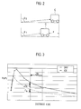
Fig. 2] Fig. 2 is a schematic view for explaining an operation of a polarization ratio calculation unit included in the road surface condition detection device according to the embodiment of the present invention. - [
Fig. 3] Fig. 3 is a view for explaining a polarization ratio for each road surface condition used in the road surface condition detection device according to the embodiment of the present invention. - [
Fig. 4] Fig. 4 is an example of refractive index information used in the road surface condition detection device according to the embodiment of the present invention. - [
Fig. 5] Fig. 5 is a schematic view for explaining a road surface condition recognition unit included in the road surface condition detection device according to the embodiment of the present invention. - [
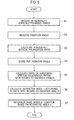
Fig. 6] Fig. 6 is a flow chart for explaining a road surface condition detection method according to the embodiment of the present invention. - Hereinafter, an embodiment of the present invention will be explained with reference to the drawings. In the following explanations of the drawings, the same or similar elements are indicated by the same or similar reference numerals. It should be noted that the embodiment described below exemplifies a device and a method to materialize the technical idea of the present invention but is not limited to the device and the method exemplified in the embodiment. The technical idea of the present invention may be subjected to various modifications within the scope of claims.
- As shown in
Fig. 1 , a road surface condition detection device according to the embodiment of the present invention includes a radio waves receiving unit 1, animage generation unit 2, a polarization ratio calculation unit 3, adistance detection unit 4, a polarization ratio storage unit 5, a refractive index calculation unit 6, a refractiveindex storage unit 7, and a road surfacecondition recognition unit 8. The road surface condition detection device according to the embodiment of the present invention is installed in a vehicle to detect road surface conditions in front of the vehicle. - The radio waves receiving unit 1 receives horizontally polarized waves and vertically polarized waves of radio waves radiated from an object which is, for example, a road surface in front of the vehicle at a radiation angle θ (an angle between a radiation direction from an object to the radio waves receiving unit 1 and a vertical direction). The radio waves receiving unit 1 includes, for example, an array antenna in which a plurality of antennas are arrayed. The radio waves receiving unit 1 has an angle of view of, for example, approximately 15° in the vertical direction and approximately 30° in the horizontal direction. Here, "radio waves" in the present invention is electromagnetic waves having a frequency approximately in the range from 30 GHz to 10 THz.
- The
image generation unit 2 generates a horizontally polarized image and a vertically polarized image based on the horizontally polarized waves and the vertically polarized waves of the radio waves, respectively, received by the radio waves receiving unit 1. The horizontally polarized image is a two-dimensional image based on a horizontally polarized waves component of the radio waves received by the radio waves receiving unit 1, and the vertically polarized waves image is a two-dimensional image based on a vertically polarized waves component of the radio waves received by the radio waves receiving unit 1. - The polarization ratio calculation unit 3 calculates a polarization ratio PH/PV, which is a ratio of intensity (received power) of the horizontally polarized waves component to the vertically polarized waves component of the radio waves received by the radio waves receiving unit 1, based on the horizontally polarized waves image and the vertically polarized waves image generated by the
image generation unit 2. - The
distance detection unit 4 detects a travel distance d of the vehicle C equipped with the road surface condition detection device according to the embodiment of the present invention. As shown inFig. 2 , the polarization ratio calculation unit 3 calculates a radiation angle θ of radio waves radiated from an object according to the travel distance d detected by thedistance detection unit 4. In the example shown inFig. 2 , when the radiation angle of the radio waves from the particular object in the initial state of the vehicle C is conceived to be θ0, the radiation angle after the vehicle C moves by the distance Δd is θ1. - The polarization ratio calculation unit 3 calculates the polarization ratio PH/PV for each radiation angle θ. The polarization ratio storage unit 5 stores, for each radiation angle θ, the polarization ratio PH/PV calculated by the polarization ratio calculation unit 3.
- The refractive index calculation unit 6 calculates a prediction refractive index n of the object based on the polarization ratio PH/PV for each radiation angle θ calculated by the polarization ratio calculation unit 3. The refractive index calculation unit 6 first calculates a ratio Γ(θ0, θ1) as a change between the polarization ratios PH/PV with regard to two radiation angles θ0 and θ1, as shown in the following formula (1).
- [Math 1]

- The refractive index calculation unit 6 then calculates the prediction refractive index n of the object according to the calculated ratio Γ(θ0, θ1) with reference to Fresnel equations, as shown in the following formula (2).
- [Math 2]

- For example, as shown in
Fig. 3 , the polarization ratio calculation unit 3 calculates the polarization ratio PH/PV of the horizontally polarized waves component to the vertically polarized waves component per travel distance d when the object is a dry road surface (each data for the dry road surface is indicated by a white rhombus "0"). Similarly, the polarization ratio calculation unit 3 calculates the polarization ratio PH/PV of the horizontally polarized waves component to the vertically polarized waves component per travel distance d when the object is an ice road surface (each data for the ice road surface is indicated by a black square "■"). - As shown in
Fig. 4 , the refractiveindex storage unit 7 stores refractive index information including items of road surface conditions in relation to refractive indexes. In the example shown inFig. 4 , the refractiveindex storage unit 7 stores the information that the refractive index is 1.2 when the road surface condition is "snow" and stores the information that the refractive index is 2 when the road surface condition is "dry". Here, the refractiveindex storage unit 7 may store ranges of values as refractive indexes. The refractive index information further includes other road surface conditions of "ice" and "wet". - The road
surface recognition unit 8 refers to the refractive index information stored in the refractiveindex storage unit 7 so as to recognize the condition of the road surface based on the refractive index of the object calculated by the refractive index calculation unit 6. - In the example shown in
Fig. 4 , the refractive index calculation unit 6 is conceived to calculate the refractive index n to be 2 according to a ratio Γa of the polarization ratios PH/PV of the two radiation angles θ0 and θ1 when the vehicle C moves by the distance Δd on the dry road surface. Then, the road surfacecondition recognition unit 8 searches the refractive index information stored in the refractiveindex storage unit 7 for a refractive index closest to the calculated refractive index, and recognizes the condition of the road surface where the vehicle is driving to be a road surface condition corresponding to the searched refractive index. Namely, the road surfacecondition recognition unit 8 recognizes the condition of the road surface where the vehicle C is driving to be "dry". - Similarly, the refractive index calculation unit 6 calculates the refractive index n to be 3 according to a ratio Γb of the polarization ratios PH/PV of the two radiation angles θ0 and θ1 when the vehicle C moves by the distance Δd on the ice road surface. Then, the road surface
condition recognition unit 8 searches the refractive index information stored in the refractiveindex storage unit 7 for a refractive index closest to the calculated refractive index, which is 2.5, and recognizes the condition of the road surface where the vehicle is driving to be a road surface condition corresponding to the searched refractive index which is "ice". - The road surface
condition recognition unit 8 may obtain an ambient temperature from atemperature detection unit 81 for detecting an ambient temperature and exclude road surface conditions to be recognized depending on the obtained ambient temperature at the time of the recognition of the road surface condition. For example, when the road surface temperature is 3°C or lower, the possibility that the road surface condition is "ice" or "snow" is low. For example, when a threshold value is set to 5°C, and when the ambient temperature is 5°C or higher, the road surfacecondition recognition unit 8 recognizes the road surface condition while excluding the condition "ice" or "snow" from the road surface conditions included in the refractive index information. - The road surface
condition recognition unit 8 includes a road surface region detection unit for detecting a road surface region corresponding to the road surface in the images generated by theimage generation unit 2. For example, the road surface region detection unit detects the road surface region based on the polarization ratio of the horizontally polarized waves to the vertically polarized waves received by the radio waves receiving unit 1. Here, received power of radio waves radiated from a flat object such as a road surface has a characteristic that the change thereof is stabilized within a particular range. Thus, the road surface region detection unit may, for example, extract a region in which the change of the received power of the radio waves received by the radio waves receiving unit 1 is within a prescribed value (for example, 5%) in the images generated by theimage generation unit 2 so as to detect the extracted region as a road surface region. - In addition, the road surface
condition recognition unit 8 may determine two regions not overlapping each other in the detected road surface region for the two refractive indexes θ0 and θ1 for which each polarization ratio PH/PV is calculated, so as to obtain a refractive index according to the degrees of intensity of the two determined regions. For example, the road surfacecondition recognition unit 8 obtains intensity PH (θw1) of the horizontally polarized waves for one of the two determined regions and intensity PV (θw0) of the vertically polarized waves for the other region, calculates a ratio Γ(θw1, θw0) from the average value of PH (θw1) and Pv (θw0), and calculates the refractive index n from the calculated Γ(θw1, θw0). - In addition, the road surface
condition recognition unit 8 may output, to avehicle control unit 91 for controlling the operation of the vehicle C, a control signal for commanding thevehicle control unit 91 to control the operation of the vehicle C. For example, as shown inFig. 5 , the road surfacecondition recognition unit 8 determines boundaries where the refractive index n changes to n1, n2 and n3 in the images generated by theimage generation unit 2, and controls the operation of the vehicle C via thevehicle control unit 91 depending on a distance to an actual position corresponding to the respective determined boundaries. The boundary corresponding to the refractive index n may be determined by spatially analyzing the polarization ratios PH/PV for the respective radiation angles θ0 and θ1 based on a region where points of reflection coincide with each other. - The
vehicle control unit 91 includes, for example, a drive unit for driving the vehicle, a braking unit for decelerating or stopping the vehicle, a steering unit for changing traveling directions of the vehicle, and the like. - In addition, the road surface
condition recognition unit 8 may determine the boundary corresponding to the refractive index n in the images generated by theimage generation unit 2 and provide a passenger with sounds, letters or images via anoutput unit 92 according to the distance to the actual position corresponding to the determined boundary. Theoutput unit 92 includes a speaker, a display unit, and the like. Further, the road surfacecondition recognition unit 8 may gradually change the output of theoutput unit 92 according to the distance to the actual position corresponding to the determined boundary. - An example of a road surface condition detection method in the road surface condition detection device according to the embodiment of the present invention is explained below with reference to the flow chart of
Fig. 6 . In the following explanation, the road surface condition detection device according to the embodiment of the present invention is a device installed in a vehicle to detect road surface conditions in a traveling direction of the vehicle. - First, in step S 1, the radio waves receiving unit 1 receives horizontally polarized waves and vertically polarized waves of radio waves radiated from an object in front of the vehicle. Next, the
image generation unit 2 generates a horizontally polarized waves image and a vertically polarized waves image based on the horizontally polarized waves and the vertically polarized waves of the radio waves, respectively, received by the radio waves receiving unit 1. - In step S2, the polarization ratio calculation unit 3 calculates a radiation angle θ of the radio waves radiated from the object according to the horizontally polarized waves image and the vertically polarized waves image generated by the
image generation unit 2 and a travel distance d of the vehicle detected by thedistance detection unit 4. - In step S3, the polarization ratio calculation unit 3 calculates a polarization ratio PH/PV, which is a ratio of intensity (received power) of a horizontally polarized waves component to a vertically polarized waves component of the radio waves received by the radio waves receiving unit 1, based on the horizontally polarized waves image and the vertically polarized waves image generated by the
image generation unit 2. - In step S4, the polarization ratio storage unit 5 stores, for each radiation angle θ, the polarization ratio PH/PV calculated by the polarization ratio calculation unit 3.
- In step S5, the refractive index calculation unit 6 calculates a ratio Γ(θ0, θ1) of the polarization ratios PH/PV with regard to the two radiation angles θ0 and θ1. In step S6, the refractive index calculation unit 6 then calculates a refractive index n of the object according to the calculated ratio Γ(θ0, θ1) with reference to Fresnel equations. The refractive index calculation unit 6 may calculate the refractive index n at prescribed timing after the polarization ratio calculation unit 3 calculates the polarization ratios PH/PV.
- In step S7, the road
surface recognition unit 8 refers to refractive index information stored in the refractiveindex storage unit 7 and recognizes the condition of the road surface based on the refractive index n of the object calculated by the refractive index calculation unit 6. - The road surface condition detection device according to the embodiment of the present invention calculates the polarization ratio of the horizontally polarized waves to the vertically polarized waves of the radio waves radiated from the object and calculates the refractive index of the object based on the ratio of the polarization ratios of the two different radiation angles so as to detect the condition of the road surface with high accuracy.
- In addition, the road surface condition detection device according to the embodiment of the present invention calculates the refractive index at prescribed timing after calculating the polarization ratios and uses some pieces of statistical time series information so as to calculate the refractive index with improved accuracy.
- In the road surface condition detection device according to the embodiment of the present invention, the refractive
index storage unit 7 stores the refractive index information including the items of the road surface conditions and recognizes the condition of the road surface while excluding particular items depending on an ambient temperature so as to reduce a risk of incorrect determination and detect the condition of the road surface with high accuracy. - In the road surface condition detection device according to the embodiment of the present invention, the road surface
condition recognition unit 8 recognizes the condition of the road surface in the detected road surface region so as to reduce a risk of incorrect determination and detect the condition of the road surface with high accuracy. - In the road surface condition detection device according to the embodiment of the present invention, the road surface
condition recognition unit 8 calculates the distance to the actual position corresponding to the boundary corresponding to the refractive index so as to preliminarily control the vehicle or provide a passenger with information. - Although the present invention has been described above by reference to the embodiment, the present invention should not be limited to the descriptions and the drawings composing part of the disclosure. It will be apparent to those skilled in the art that various alternative embodiments, examples and implementations can be made.
- For example, in the embodiment described above, the road surface condition detection device may include two radio waves receiving units 1 aligned in the vertical direction for separately detecting horizontally polarized waves and vertically polarized waves so as to calculate polarization ratios PH/PV of two radiation angles. The polarization ratios PH/PV are calculated by use of the difference of elevation of the two radio waves receiving units 1 having different heights so as to detect the condition of the road surface with high accuracy even when the vehicle is being stopped. For example, the lower radio waves receiving unit 1 is arranged at a height in the range from 30 to 50 cm, and the difference of height of the upper and lower units is in the range from 30 to 50 cm. Alternatively, three radio waves receiving units 1 may be used to calculate polarization ratios PH/PV so as to calculate a refractive index of an object other than the road surface.
- In the embodiment described above, the polarization ratio calculation unit 3 may detect an inclination of a road surface where the vehicle is driving so as to correct a radiation angle θ according to the detected inclination of the road surface. The inclination of the road surface may be obtained by use of, for example, a GPS receiver and map data, a gyro sensor, or an acceleration sensor. Accordingly, the radiation angle θ can be corrected precisely even if the radiation angle necessary for calculating a refractive index n is incorrectly calculated so as to detect the condition of the road surface with high accuracy.
- The present invention can, of course, include various embodiments not described in this specification. Therefore, the scope of the present invention is defined only by the appropriate features according to the claims in view of the explanations made above.
- The entire content of Japanese Patent Application No.
P2012-175865 (filed on August 8, 2012 - The present invention can provide a road surface condition detection device and a road surface condition detection method capable of detecting road surface conditions with high accuracy regardless of weather.
-
- 1
- RADIO WAVES RECEIVING UNIT
- 2
- IMAGE GENERATION UNIT
- 3
- POLARIZATION RATIO CALCULATION UNIT
- 6
- REFRACTIVE INDEX CALCULATION UNIT
- 7
- REFRACTIVE INDEX STORAGE UNIT
- 8
- ROAD SURFACE CONDITION RECOGNITION UNIT
Claims (9)
- A road surface condition detection device comprising:a radio waves receiving unit configured to receive horizontally polarized waves and vertically polarized waves of radio waves radiated from an object at a radiation angle;an image generation unit configured to generate a horizontally polarized waves image and a vertically polarized waves image based on the horizontally polarized waves and the vertically polarized waves, respectively, received by the radio waves receiving unit;a polarization ratio calculation unit configured to calculate, for each radiation angle, a polarization ratio which is a ratio of intensity of the horizontally polarized waves to the vertically polarized waves based on the horizontally polarized waves image and the vertically polarized waves image generated by the image generation unit;a refractive index calculation unit configured to calculate a refractive index of the object according to a change between polarization ratios of two different radiation angles calculated by the polarization ratio calculation unit; anda road surface condition recognition unit configured to recognize a condition of a road surface based on the refractive index calculated by the refractive index calculation unit.
- The road surface condition detection device according to claim 1, wherein:the road surface condition detection device is installed in a vehicle; andthe polarization ratio calculation unit calculates the polarization ratios of the two different radiation angles according to a change in travel distance.
- The road surface condition detection device according to claim 1, comprising two radio waves receiving units aligned in a vertical direction, each of the two radio waves receiving units corresponding to the radio waves receiving unit,
wherein the polarization ratio calculation unit calculates the polarization ratios of the two different radiation angles by use of a difference of elevation of the two radio waves receiving units. - The road surface condition detection device according to claim 1 or 2, wherein the refractive index calculation unit calculates the refractive index at prescribed timing after the polarization ratio calculation unit calculates the polarization ratios.
- The road surface condition detection device according to any one of claims 1 to 4, further comprising a refractive index storage unit configured to store refractive index information including items of road surface conditions in relation to refractive indexes,
wherein the road surface condition recognition unit recognizes the condition of the road surface based on the refractive index calculated by the refractive index calculation unit with reference to the refractive index information stored in the refractive index storage unit. - The road surface condition detection device according to claim 5, wherein the road surface condition recognition unit recognizes the condition of the road surface in such a manner as to exclude an prescribed item of the road surface conditions in the refractive index information depending on an ambient temperature.
- The road surface condition detection device according to any one of claims 1 to 6, wherein the road surface condition recognition unit detects a road surface region corresponding to the road surface in the images generated by the image generation unit so as to recognize the condition of the road surface in the detected road surface region.
- The road surface condition detection device according to any one of claims 1 to 7, wherein the road surface condition recognition unit determines a boundary corresponding to the refractive index calculated by the refractive index calculation unit in the images generated by the image generation unit so as to calculate a distance to an actual position corresponding to the boundary.
- A road surface condition detection method comprising:receiving horizontally polarized waves and vertically polarized waves of radio waves radiated from an object at a radiation angle;generating a horizontally polarized waves image and a vertically polarized waves image based on the received horizontally polarized waves and vertically polarized waves, respectively;calculating, for each radiation angle, a polarization ratio which is a ratio of intensity of the horizontally polarized waves to the vertically polarized waves based on the generated horizontally polarized waves image and vertically polarized waves image;calculating a refractive index of the object according to a change between calculated polarization ratios of two different radiation angles; andrecognizing a condition of a road surface based on the calculated refractive index.
Applications Claiming Priority (2)
| Application Number | Priority Date | Filing Date | Title |
|---|---|---|---|
| JP2012175865 | 2012-08-08 | ||
| PCT/JP2013/070847 WO2014024763A1 (en) | 2012-08-08 | 2013-08-01 | Road surface state detection device and road surface state detection method |
Publications (3)
| Publication Number | Publication Date |
|---|---|
| EP2884311A1 true EP2884311A1 (en) | 2015-06-17 |
| EP2884311A4 EP2884311A4 (en) | 2015-10-07 |
| EP2884311B1 EP2884311B1 (en) | 2017-07-19 |
Family
ID=50067994
Family Applications (1)
| Application Number | Title | Priority Date | Filing Date |
|---|---|---|---|
| EP13828642.2A Active EP2884311B1 (en) | 2012-08-08 | 2013-08-01 | Road surface state detection device and road surface state detection method |
Country Status (5)
| Country | Link |
|---|---|
| US (1) | US9341708B2 (en) |
| EP (1) | EP2884311B1 (en) |
| JP (1) | JP5907271B2 (en) |
| CN (1) | CN104520735B (en) |
| WO (1) | WO2014024763A1 (en) |
Families Citing this family (12)
| Publication number | Priority date | Publication date | Assignee | Title |
|---|---|---|---|---|
| GB2523091B (en) * | 2014-02-12 | 2017-11-01 | Jaguar Land Rover Ltd | A system for use in a vehicle |
| JP6424488B2 (en) * | 2014-06-19 | 2018-11-21 | 日産自動車株式会社 | Object detection apparatus and object detection method |
| WO2015194042A1 (en) * | 2014-06-20 | 2015-12-23 | 日産自動車株式会社 | Radio wave image generation device and radio wave image generation method |
| JP6477350B2 (en) * | 2015-08-10 | 2019-03-06 | 日産自動車株式会社 | Method for controlling road surface detection device and road surface detection device |
| US10360459B2 (en) * | 2016-04-06 | 2019-07-23 | Panasonic Intellectual Property Management Co., Ltd. | Detection device, detection method, and non-transitory computer-readable recording medium storing detection program |
| JP6809166B2 (en) * | 2016-11-25 | 2021-01-06 | 日産自動車株式会社 | Road surface judgment method and road surface judgment device |
| JP7001305B2 (en) * | 2017-06-06 | 2022-01-19 | 株式会社豊田中央研究所 | Road surface condition determination device and road surface condition determination program |
| US10872419B2 (en) * | 2018-09-04 | 2020-12-22 | GM Global Technology Operations LLC | Method and apparatus for evaluating a vehicle travel surface |
| US11402489B2 (en) * | 2019-12-17 | 2022-08-02 | Hewlett Packard Enterprise Development Lp | Passive multi-person location tracking utilizing signal polarization |
| EP4152040B1 (en) * | 2021-09-17 | 2025-04-02 | Aptiv Technologies AG | Method and radar system for determining road conditions |
| EP4303608A1 (en) * | 2022-07-05 | 2024-01-10 | Aptiv Technologies Limited | Radar system for automotive applications |
| EP4303610A1 (en) * | 2022-07-06 | 2024-01-10 | Aptiv Technologies Limited | Radar system for automotive applications |
Family Cites Families (15)
| Publication number | Priority date | Publication date | Assignee | Title |
|---|---|---|---|---|
| DE19715999A1 (en) * | 1997-04-17 | 1998-10-22 | Daimler Benz Ag | Radar arrangement for road condition detection in a motor vehicle |
| DE19718623A1 (en) * | 1997-05-02 | 1998-11-05 | Daimler Benz Ag | Method for polarimetric lane recognition |
| DE19963001A1 (en) * | 1999-12-24 | 2001-06-28 | Bosch Gmbh Robert | Motor vehicle radar system for focussing sensor beams to control speed feeds external temperature and vehicle net speed from a CAN bus to a control device via control wires. |
| JP2002310896A (en) * | 2001-04-19 | 2002-10-23 | Mitsubishi Heavy Ind Ltd | Road surface condition discriminating device and road surface condition discriminating method |
| JP3671229B2 (en) | 2002-11-26 | 2005-07-13 | 国土交通省国土技術政策総合研究所長 | Radio radiometer type road surface condition grasping device |
| ATE375585T1 (en) * | 2003-03-14 | 2007-10-15 | Liwas Aps | DEVICE FOR DETECTING A ROAD SURFACE CONDITION |
| US7167126B2 (en) * | 2004-09-01 | 2007-01-23 | The Boeing Company | Radar system and method for determining the height of an object |
| JP4556765B2 (en) * | 2005-05-19 | 2010-10-06 | 株式会社デンソー | Radio wave reception system and imaging system |
| JP2007140992A (en) | 2005-11-18 | 2007-06-07 | Aisin Aw Co Ltd | Method and device for supporting driving at intersection |
| JP5610254B2 (en) * | 2008-06-18 | 2014-10-22 | 株式会社リコー | Imaging apparatus and road surface state determination method |
| FI121250B (en) * | 2008-09-11 | 2010-08-31 | Valtion Teknillinen | Method for identifying road conditions |
| JP5461065B2 (en) * | 2009-05-21 | 2014-04-02 | クラリオン株式会社 | Current position specifying device and current position specifying method |
| JP5664152B2 (en) * | 2009-12-25 | 2015-02-04 | 株式会社リコー | Imaging device, in-vehicle imaging system, and object identification device |
| JP5779965B2 (en) * | 2010-08-30 | 2015-09-16 | 日産自動車株式会社 | Object detection apparatus and object detection method |
| US9081086B2 (en) * | 2012-03-01 | 2015-07-14 | Nissan Motor Co., Ltd. | Vehicle detection device and vehicle detection method |
-
2013
- 2013-08-01 CN CN201380041971.4A patent/CN104520735B/en active Active
- 2013-08-01 JP JP2014529457A patent/JP5907271B2/en active Active
- 2013-08-01 WO PCT/JP2013/070847 patent/WO2014024763A1/en not_active Ceased
- 2013-08-01 EP EP13828642.2A patent/EP2884311B1/en active Active
- 2013-08-01 US US14/419,758 patent/US9341708B2/en active Active
Also Published As
| Publication number | Publication date |
|---|---|
| US20150212199A1 (en) | 2015-07-30 |
| CN104520735A (en) | 2015-04-15 |
| WO2014024763A1 (en) | 2014-02-13 |
| JP5907271B2 (en) | 2016-04-26 |
| JPWO2014024763A1 (en) | 2016-07-25 |
| CN104520735B (en) | 2016-03-02 |
| EP2884311A4 (en) | 2015-10-07 |
| US9341708B2 (en) | 2016-05-17 |
| EP2884311B1 (en) | 2017-07-19 |
Similar Documents
| Publication | Publication Date | Title |
|---|---|---|
| EP2884311B1 (en) | Road surface state detection device and road surface state detection method | |
| CN111352110B (en) | Method and device for processing radar data | |
| US9713983B2 (en) | Lane boundary line recognition apparatus and program for recognizing lane boundary line on roadway | |
| US10353051B2 (en) | Apparatus for detecting axial misalignment of beam sensor | |
| EP3229041B1 (en) | Object detection using radar and vision defined image detection zone | |
| US9934690B2 (en) | Object recognition apparatus and vehicle travel controller using same | |
| JP6189815B2 (en) | Traveling line recognition system | |
| US9262693B2 (en) | Object detection apparatus | |
| US20140156178A1 (en) | Road marker recognition device and method | |
| JP6468136B2 (en) | Driving support device and driving support method | |
| US10121379B2 (en) | Apparatus for safety-driving of vehicle | |
| KR20210096608A (en) | Initial fusion of camera and radar frames | |
| EP2889641A1 (en) | Image processing apparatus, image processing method, program and image processing system | |
| CN104573646A (en) | Detection method and system, based on laser radar and binocular camera, for pedestrian in front of vehicle | |
| US20150098076A1 (en) | Apparatus and method for recognizing vehicle | |
| US11156712B2 (en) | Automotive radar system with direct measurement of yaw rate and/or heading of object vehicle | |
| KR20160051993A (en) | Apparatus for driver assistance | |
| US9530063B2 (en) | Lane-line recognition apparatus including a masking area setter to set a masking area ahead of a vehicle in an image captured by an image capture unit | |
| US20110227781A1 (en) | Method and apparatus for detecting road-edges | |
| JP2019518946A (en) | Radar sensor device for a motor vehicle, driver assistance system, motor vehicle and method for sensing an object | |
| US20200108837A1 (en) | Device, method, and system for controling road curvature of vehicle | |
| KR20190050238A (en) | Autonomous Emergencyy Braking System and Controlling Method Thereof | |
| WO2019060519A1 (en) | Variable range and frame-rate radar operation for automated vehicle | |
| EP3865909B1 (en) | Electronic device, method for controlling electronic device, and program for controlling electronic device | |
| WO2015119298A1 (en) | Axis deviation detection device for beam sensor |
Legal Events
| Date | Code | Title | Description |
|---|---|---|---|
| PUAI | Public reference made under article 153(3) epc to a published international application that has entered the european phase |
Free format text: ORIGINAL CODE: 0009012 |
|
| 17P | Request for examination filed |
Effective date: 20150304 |
|
| AK | Designated contracting states |
Kind code of ref document: A1 Designated state(s): AL AT BE BG CH CY CZ DE DK EE ES FI FR GB GR HR HU IE IS IT LI LT LU LV MC MK MT NL NO PL PT RO RS SE SI SK SM TR |
|
| AX | Request for extension of the european patent |
Extension state: BA ME |
|
| RA4 | Supplementary search report drawn up and despatched (corrected) |
Effective date: 20150909 |
|
| RIC1 | Information provided on ipc code assigned before grant |
Ipc: G01N 22/04 20060101ALI20150903BHEP Ipc: G01W 1/14 20060101ALI20150903BHEP Ipc: G01W 1/00 20060101AFI20150903BHEP Ipc: G06K 9/00 20060101ALI20150903BHEP |
|
| DAX | Request for extension of the european patent (deleted) | ||
| 17Q | First examination report despatched |
Effective date: 20160713 |
|
| GRAP | Despatch of communication of intention to grant a patent |
Free format text: ORIGINAL CODE: EPIDOSNIGR1 |
|
| INTG | Intention to grant announced |
Effective date: 20170322 |
|
| GRAS | Grant fee paid |
Free format text: ORIGINAL CODE: EPIDOSNIGR3 |
|
| GRAA | (expected) grant |
Free format text: ORIGINAL CODE: 0009210 |
|
| AK | Designated contracting states |
Kind code of ref document: B1 Designated state(s): AL AT BE BG CH CY CZ DE DK EE ES FI FR GB GR HR HU IE IS IT LI LT LU LV MC MK MT NL NO PL PT RO RS SE SI SK SM TR |
|
| REG | Reference to a national code |
Ref country code: GB Ref legal event code: FG4D |
|
| REG | Reference to a national code |
Ref country code: CH Ref legal event code: EP |
|
| REG | Reference to a national code |
Ref country code: IE Ref legal event code: FG4D |
|
| REG | Reference to a national code |
Ref country code: AT Ref legal event code: REF Ref document number: 910913 Country of ref document: AT Kind code of ref document: T Effective date: 20170815 |
|
| REG | Reference to a national code |
Ref country code: FR Ref legal event code: PLFP Year of fee payment: 5 |
|
| REG | Reference to a national code |
Ref country code: DE Ref legal event code: R096 Ref document number: 602013023863 Country of ref document: DE |
|
| REG | Reference to a national code |
Ref country code: NL Ref legal event code: MP Effective date: 20170719 |
|
| REG | Reference to a national code |
Ref country code: LT Ref legal event code: MG4D |
|
| REG | Reference to a national code |
Ref country code: AT Ref legal event code: MK05 Ref document number: 910913 Country of ref document: AT Kind code of ref document: T Effective date: 20170719 |
|
| PG25 | Lapsed in a contracting state [announced via postgrant information from national office to epo] |
Ref country code: HR Free format text: LAPSE BECAUSE OF FAILURE TO SUBMIT A TRANSLATION OF THE DESCRIPTION OR TO PAY THE FEE WITHIN THE PRESCRIBED TIME-LIMIT Effective date: 20170719 Ref country code: SE Free format text: LAPSE BECAUSE OF FAILURE TO SUBMIT A TRANSLATION OF THE DESCRIPTION OR TO PAY THE FEE WITHIN THE PRESCRIBED TIME-LIMIT Effective date: 20170719 Ref country code: FI Free format text: LAPSE BECAUSE OF FAILURE TO SUBMIT A TRANSLATION OF THE DESCRIPTION OR TO PAY THE FEE WITHIN THE PRESCRIBED TIME-LIMIT Effective date: 20170719 Ref country code: LT Free format text: LAPSE BECAUSE OF FAILURE TO SUBMIT A TRANSLATION OF THE DESCRIPTION OR TO PAY THE FEE WITHIN THE PRESCRIBED TIME-LIMIT Effective date: 20170719 Ref country code: NL Free format text: LAPSE BECAUSE OF FAILURE TO SUBMIT A TRANSLATION OF THE DESCRIPTION OR TO PAY THE FEE WITHIN THE PRESCRIBED TIME-LIMIT Effective date: 20170719 Ref country code: AT Free format text: LAPSE BECAUSE OF FAILURE TO SUBMIT A TRANSLATION OF THE DESCRIPTION OR TO PAY THE FEE WITHIN THE PRESCRIBED TIME-LIMIT Effective date: 20170719 Ref country code: NO Free format text: LAPSE BECAUSE OF FAILURE TO SUBMIT A TRANSLATION OF THE DESCRIPTION OR TO PAY THE FEE WITHIN THE PRESCRIBED TIME-LIMIT Effective date: 20171019 |
|
| PG25 | Lapsed in a contracting state [announced via postgrant information from national office to epo] |
Ref country code: IS Free format text: LAPSE BECAUSE OF FAILURE TO SUBMIT A TRANSLATION OF THE DESCRIPTION OR TO PAY THE FEE WITHIN THE PRESCRIBED TIME-LIMIT Effective date: 20171119 Ref country code: BG Free format text: LAPSE BECAUSE OF FAILURE TO SUBMIT A TRANSLATION OF THE DESCRIPTION OR TO PAY THE FEE WITHIN THE PRESCRIBED TIME-LIMIT Effective date: 20171019 Ref country code: ES Free format text: LAPSE BECAUSE OF FAILURE TO SUBMIT A TRANSLATION OF THE DESCRIPTION OR TO PAY THE FEE WITHIN THE PRESCRIBED TIME-LIMIT Effective date: 20170719 Ref country code: LV Free format text: LAPSE BECAUSE OF FAILURE TO SUBMIT A TRANSLATION OF THE DESCRIPTION OR TO PAY THE FEE WITHIN THE PRESCRIBED TIME-LIMIT Effective date: 20170719 Ref country code: RS Free format text: LAPSE BECAUSE OF FAILURE TO SUBMIT A TRANSLATION OF THE DESCRIPTION OR TO PAY THE FEE WITHIN THE PRESCRIBED TIME-LIMIT Effective date: 20170719 Ref country code: PL Free format text: LAPSE BECAUSE OF FAILURE TO SUBMIT A TRANSLATION OF THE DESCRIPTION OR TO PAY THE FEE WITHIN THE PRESCRIBED TIME-LIMIT Effective date: 20170719 Ref country code: GR Free format text: LAPSE BECAUSE OF FAILURE TO SUBMIT A TRANSLATION OF THE DESCRIPTION OR TO PAY THE FEE WITHIN THE PRESCRIBED TIME-LIMIT Effective date: 20171020 |
|
| REG | Reference to a national code |
Ref country code: CH Ref legal event code: PL |
|
| REG | Reference to a national code |
Ref country code: DE Ref legal event code: R097 Ref document number: 602013023863 Country of ref document: DE |
|
| PG25 | Lapsed in a contracting state [announced via postgrant information from national office to epo] |
Ref country code: CH Free format text: LAPSE BECAUSE OF NON-PAYMENT OF DUE FEES Effective date: 20170831 Ref country code: CZ Free format text: LAPSE BECAUSE OF FAILURE TO SUBMIT A TRANSLATION OF THE DESCRIPTION OR TO PAY THE FEE WITHIN THE PRESCRIBED TIME-LIMIT Effective date: 20170719 Ref country code: RO Free format text: LAPSE BECAUSE OF FAILURE TO SUBMIT A TRANSLATION OF THE DESCRIPTION OR TO PAY THE FEE WITHIN THE PRESCRIBED TIME-LIMIT Effective date: 20170719 Ref country code: LI Free format text: LAPSE BECAUSE OF NON-PAYMENT OF DUE FEES Effective date: 20170831 Ref country code: MC Free format text: LAPSE BECAUSE OF FAILURE TO SUBMIT A TRANSLATION OF THE DESCRIPTION OR TO PAY THE FEE WITHIN THE PRESCRIBED TIME-LIMIT Effective date: 20170719 Ref country code: DK Free format text: LAPSE BECAUSE OF FAILURE TO SUBMIT A TRANSLATION OF THE DESCRIPTION OR TO PAY THE FEE WITHIN THE PRESCRIBED TIME-LIMIT Effective date: 20170719 |
|
| PLBE | No opposition filed within time limit |
Free format text: ORIGINAL CODE: 0009261 |
|
| STAA | Information on the status of an ep patent application or granted ep patent |
Free format text: STATUS: NO OPPOSITION FILED WITHIN TIME LIMIT |
|
| REG | Reference to a national code |
Ref country code: IE Ref legal event code: MM4A |
|
| PG25 | Lapsed in a contracting state [announced via postgrant information from national office to epo] |
Ref country code: SK Free format text: LAPSE BECAUSE OF FAILURE TO SUBMIT A TRANSLATION OF THE DESCRIPTION OR TO PAY THE FEE WITHIN THE PRESCRIBED TIME-LIMIT Effective date: 20170719 Ref country code: SM Free format text: LAPSE BECAUSE OF FAILURE TO SUBMIT A TRANSLATION OF THE DESCRIPTION OR TO PAY THE FEE WITHIN THE PRESCRIBED TIME-LIMIT Effective date: 20170719 Ref country code: EE Free format text: LAPSE BECAUSE OF FAILURE TO SUBMIT A TRANSLATION OF THE DESCRIPTION OR TO PAY THE FEE WITHIN THE PRESCRIBED TIME-LIMIT Effective date: 20170719 Ref country code: IT Free format text: LAPSE BECAUSE OF FAILURE TO SUBMIT A TRANSLATION OF THE DESCRIPTION OR TO PAY THE FEE WITHIN THE PRESCRIBED TIME-LIMIT Effective date: 20170719 |
|
| REG | Reference to a national code |
Ref country code: FR Ref legal event code: PLFP Year of fee payment: 6 |
|
| REG | Reference to a national code |
Ref country code: BE Ref legal event code: MM Effective date: 20170831 |
|
| 26N | No opposition filed |
Effective date: 20180420 |
|
| PG25 | Lapsed in a contracting state [announced via postgrant information from national office to epo] |
Ref country code: LU Free format text: LAPSE BECAUSE OF NON-PAYMENT OF DUE FEES Effective date: 20170801 |
|
| PG25 | Lapsed in a contracting state [announced via postgrant information from national office to epo] |
Ref country code: IE Free format text: LAPSE BECAUSE OF NON-PAYMENT OF DUE FEES Effective date: 20170801 |
|
| PG25 | Lapsed in a contracting state [announced via postgrant information from national office to epo] |
Ref country code: BE Free format text: LAPSE BECAUSE OF NON-PAYMENT OF DUE FEES Effective date: 20170831 Ref country code: SI Free format text: LAPSE BECAUSE OF FAILURE TO SUBMIT A TRANSLATION OF THE DESCRIPTION OR TO PAY THE FEE WITHIN THE PRESCRIBED TIME-LIMIT Effective date: 20170719 |
|
| PG25 | Lapsed in a contracting state [announced via postgrant information from national office to epo] |
Ref country code: MT Free format text: LAPSE BECAUSE OF NON-PAYMENT OF DUE FEES Effective date: 20170801 |
|
| PG25 | Lapsed in a contracting state [announced via postgrant information from national office to epo] |
Ref country code: HU Free format text: LAPSE BECAUSE OF FAILURE TO SUBMIT A TRANSLATION OF THE DESCRIPTION OR TO PAY THE FEE WITHIN THE PRESCRIBED TIME-LIMIT; INVALID AB INITIO Effective date: 20130801 |
|
| PG25 | Lapsed in a contracting state [announced via postgrant information from national office to epo] |
Ref country code: CY Free format text: LAPSE BECAUSE OF FAILURE TO SUBMIT A TRANSLATION OF THE DESCRIPTION OR TO PAY THE FEE WITHIN THE PRESCRIBED TIME-LIMIT Effective date: 20170719 |
|
| PG25 | Lapsed in a contracting state [announced via postgrant information from national office to epo] |
Ref country code: MK Free format text: LAPSE BECAUSE OF FAILURE TO SUBMIT A TRANSLATION OF THE DESCRIPTION OR TO PAY THE FEE WITHIN THE PRESCRIBED TIME-LIMIT Effective date: 20170719 |
|
| PG25 | Lapsed in a contracting state [announced via postgrant information from national office to epo] |
Ref country code: TR Free format text: LAPSE BECAUSE OF FAILURE TO SUBMIT A TRANSLATION OF THE DESCRIPTION OR TO PAY THE FEE WITHIN THE PRESCRIBED TIME-LIMIT Effective date: 20170719 |
|
| PG25 | Lapsed in a contracting state [announced via postgrant information from national office to epo] |
Ref country code: PT Free format text: LAPSE BECAUSE OF FAILURE TO SUBMIT A TRANSLATION OF THE DESCRIPTION OR TO PAY THE FEE WITHIN THE PRESCRIBED TIME-LIMIT Effective date: 20170719 |
|
| PG25 | Lapsed in a contracting state [announced via postgrant information from national office to epo] |
Ref country code: AL Free format text: LAPSE BECAUSE OF FAILURE TO SUBMIT A TRANSLATION OF THE DESCRIPTION OR TO PAY THE FEE WITHIN THE PRESCRIBED TIME-LIMIT Effective date: 20170719 |
|
| PGFP | Annual fee paid to national office [announced via postgrant information from national office to epo] |
Ref country code: DE Payment date: 20250724 Year of fee payment: 13 |
|
| PGFP | Annual fee paid to national office [announced via postgrant information from national office to epo] |
Ref country code: GB Payment date: 20250725 Year of fee payment: 13 |
|
| PGFP | Annual fee paid to national office [announced via postgrant information from national office to epo] |
Ref country code: FR Payment date: 20250723 Year of fee payment: 13 |