EP2884286A1 - Unité de transport des supports de tubes à essais et appareil d'analyse - Google Patents
Unité de transport des supports de tubes à essais et appareil d'analyse Download PDFInfo
- Publication number
- EP2884286A1 EP2884286A1 EP13196392.8A EP13196392A EP2884286A1 EP 2884286 A1 EP2884286 A1 EP 2884286A1 EP 13196392 A EP13196392 A EP 13196392A EP 2884286 A1 EP2884286 A1 EP 2884286A1
- Authority
- EP
- European Patent Office
- Prior art keywords
- rack
- carrier
- tube
- pusher
- input
- Prior art date
- Legal status (The legal status is an assumption and is not a legal conclusion. Google has not performed a legal analysis and makes no representation as to the accuracy of the status listed.)
- Granted
Links
- 238000012546 transfer Methods 0.000 title claims abstract description 131
- 238000005070 sampling Methods 0.000 claims abstract description 53
- 239000000523 sample Substances 0.000 claims abstract description 46
- 238000000338 in vitro Methods 0.000 claims abstract description 12
- 239000000969 carrier Substances 0.000 claims abstract description 9
- 239000012472 biological sample Substances 0.000 claims abstract description 5
- 238000002405 diagnostic procedure Methods 0.000 claims abstract description 4
- 238000004458 analytical method Methods 0.000 description 5
- 238000012360 testing method Methods 0.000 description 5
- 238000010276 construction Methods 0.000 description 3
- 229920003023 plastic Polymers 0.000 description 3
- 239000004033 plastic Substances 0.000 description 3
- 239000011521 glass Substances 0.000 description 2
- 238000000034 method Methods 0.000 description 2
- 238000011160 research Methods 0.000 description 2
- 230000001419 dependent effect Effects 0.000 description 1
- 239000007788 liquid Substances 0.000 description 1
- 230000007774 longterm Effects 0.000 description 1
- 238000012986 modification Methods 0.000 description 1
- 230000004048 modification Effects 0.000 description 1
Images


Classifications
-
- G—PHYSICS
- G01—MEASURING; TESTING
- G01N—INVESTIGATING OR ANALYSING MATERIALS BY DETERMINING THEIR CHEMICAL OR PHYSICAL PROPERTIES
- G01N35/00—Automatic analysis not limited to methods or materials provided for in any single one of groups G01N1/00 - G01N33/00; Handling materials therefor
- G01N35/02—Automatic analysis not limited to methods or materials provided for in any single one of groups G01N1/00 - G01N33/00; Handling materials therefor using a plurality of sample containers moved by a conveyor system past one or more treatment or analysis stations
- G01N35/026—Automatic analysis not limited to methods or materials provided for in any single one of groups G01N1/00 - G01N33/00; Handling materials therefor using a plurality of sample containers moved by a conveyor system past one or more treatment or analysis stations having blocks or racks of reaction cells or cuvettes
-
- B—PERFORMING OPERATIONS; TRANSPORTING
- B65—CONVEYING; PACKING; STORING; HANDLING THIN OR FILAMENTARY MATERIAL
- B65G—TRANSPORT OR STORAGE DEVICES, e.g. CONVEYORS FOR LOADING OR TIPPING, SHOP CONVEYOR SYSTEMS OR PNEUMATIC TUBE CONVEYORS
- B65G47/00—Article or material-handling devices associated with conveyors; Methods employing such devices
- B65G47/74—Feeding, transfer, or discharging devices of particular kinds or types
- B65G47/82—Rotary or reciprocating members for direct action on articles or materials, e.g. pushers, rakes, shovels
-
- G—PHYSICS
- G01—MEASURING; TESTING
- G01N—INVESTIGATING OR ANALYSING MATERIALS BY DETERMINING THEIR CHEMICAL OR PHYSICAL PROPERTIES
- G01N35/00—Automatic analysis not limited to methods or materials provided for in any single one of groups G01N1/00 - G01N33/00; Handling materials therefor
- G01N35/02—Automatic analysis not limited to methods or materials provided for in any single one of groups G01N1/00 - G01N33/00; Handling materials therefor using a plurality of sample containers moved by a conveyor system past one or more treatment or analysis stations
- G01N35/04—Details of the conveyor system
-
- B—PERFORMING OPERATIONS; TRANSPORTING
- B65—CONVEYING; PACKING; STORING; HANDLING THIN OR FILAMENTARY MATERIAL
- B65G—TRANSPORT OR STORAGE DEVICES, e.g. CONVEYORS FOR LOADING OR TIPPING, SHOP CONVEYOR SYSTEMS OR PNEUMATIC TUBE CONVEYORS
- B65G2201/00—Indexing codes relating to handling devices, e.g. conveyors, characterised by the type of product or load being conveyed or handled
- B65G2201/02—Articles
- B65G2201/0235—Containers
-
- B—PERFORMING OPERATIONS; TRANSPORTING
- B65—CONVEYING; PACKING; STORING; HANDLING THIN OR FILAMENTARY MATERIAL
- B65G—TRANSPORT OR STORAGE DEVICES, e.g. CONVEYORS FOR LOADING OR TIPPING, SHOP CONVEYOR SYSTEMS OR PNEUMATIC TUBE CONVEYORS
- B65G25/00—Conveyors comprising a cyclically-moving, e.g. reciprocating, carrier or impeller which is disengaged from the load during the return part of its movement
- B65G25/04—Conveyors comprising a cyclically-moving, e.g. reciprocating, carrier or impeller which is disengaged from the load during the return part of its movement the carrier or impeller having identical forward and return paths of movement, e.g. reciprocating conveyors
- B65G25/08—Conveyors comprising a cyclically-moving, e.g. reciprocating, carrier or impeller which is disengaged from the load during the return part of its movement the carrier or impeller having identical forward and return paths of movement, e.g. reciprocating conveyors having impellers, e.g. pushers
-
- G—PHYSICS
- G01—MEASURING; TESTING
- G01N—INVESTIGATING OR ANALYSING MATERIALS BY DETERMINING THEIR CHEMICAL OR PHYSICAL PROPERTIES
- G01N35/00—Automatic analysis not limited to methods or materials provided for in any single one of groups G01N1/00 - G01N33/00; Handling materials therefor
- G01N35/02—Automatic analysis not limited to methods or materials provided for in any single one of groups G01N1/00 - G01N33/00; Handling materials therefor using a plurality of sample containers moved by a conveyor system past one or more treatment or analysis stations
- G01N35/04—Details of the conveyor system
- G01N2035/0401—Sample carriers, cuvettes or reaction vessels
- G01N2035/0412—Block or rack elements with a single row of samples
- G01N2035/0415—Block or rack elements with a single row of samples moving in two dimensions in a horizontal plane
-
- G—PHYSICS
- G01—MEASURING; TESTING
- G01N—INVESTIGATING OR ANALYSING MATERIALS BY DETERMINING THEIR CHEMICAL OR PHYSICAL PROPERTIES
- G01N35/00—Automatic analysis not limited to methods or materials provided for in any single one of groups G01N1/00 - G01N33/00; Handling materials therefor
- G01N35/02—Automatic analysis not limited to methods or materials provided for in any single one of groups G01N1/00 - G01N33/00; Handling materials therefor using a plurality of sample containers moved by a conveyor system past one or more treatment or analysis stations
- G01N35/04—Details of the conveyor system
- G01N2035/0474—Details of actuating means for conveyors or pipettes
- G01N2035/0475—Details of actuating means for conveyors or pipettes electric, e.g. stepper motor, solenoid
-
- Y—GENERAL TAGGING OF NEW TECHNOLOGICAL DEVELOPMENTS; GENERAL TAGGING OF CROSS-SECTIONAL TECHNOLOGIES SPANNING OVER SEVERAL SECTIONS OF THE IPC; TECHNICAL SUBJECTS COVERED BY FORMER USPC CROSS-REFERENCE ART COLLECTIONS [XRACs] AND DIGESTS
- Y10—TECHNICAL SUBJECTS COVERED BY FORMER USPC
- Y10T—TECHNICAL SUBJECTS COVERED BY FORMER US CLASSIFICATION
- Y10T436/00—Chemistry: analytical and immunological testing
- Y10T436/11—Automated chemical analysis
- Y10T436/113332—Automated chemical analysis with conveyance of sample along a test line in a container or rack
Definitions
- the present invention is in the field of biochemical research, biochemical routine analytics, clinical diagnostics and clinical research and relates to a tube rack transfer device for transferring tube racks and an in-vitro diagnostic instrument comprising at least one such tube rack transfer device.
- sample tube herein interchangeably referred to as “tube” is either a sample collection test tube, also called “primary tube”, used to receive a sample from a patient and to transport the sample contained therein to an analytical laboratory for diagnostics purposes, or a “secondary tube”, which may be used to receive an aliquot of sample from a primary tube.
- a primary sample tube is typically made of glass or plastics, has a closed end and an open end, typically closed by a closure.
- a secondary tube is typically made of plastics and may have a lower degree of variation of size and type with respect to primary tubes. In particular, secondary tubes may be smaller than primary tubes and be designed to be closed with one type or similar types of closure, e.g. of the screw type.
- the test tube can, e.g., be a tubular test tube which may, e.g., have a cylindrical shaft closed on the bottom side by a rounded, e.g. hemispherical, bottom.
- a “tube rack”, herein interchangeably referred to as “rack”, relates to a tube holder provided with a plurality of tube seats for holding test tubes.
- the tube rack can, e.g., be configured to hold test tubes in an upright manner, e.g., aligned in a row.
- a new device for transferring tube racks is proposed.
- the tube rack transfer device comprises a first rail extending a first direction and a second rail extending in a second direction orthogonal to the first direction, with the second rail being movable along the first rail and the transfer head being movable along the second rail.
- At least one transfer head is movably fixed to the second rail in a manner to be movable along the second rails.
- the transfer head comprises at least one control pin adapted to be coupled with at least one of:
- the device for transferring tube racks comprises a transfer lane extending along the first horizontal direction and arranged between at least two rack carriers in such a manner that a tube rack can be transferred between different rack carriers and/or between a rack carrier and the sampling area via the transfer lane.
- the second rail comprises a transfer lane pin linearly translatable together with the second rail in the first horizontal direction for moving a tube rack along the transfer lane.
- the device for transferring tube racks comprises a rack transport shuttle for transporting a tube rack, arranged in a manner to receive/provide a tube rack from/to the transport lane.
- the transfer head comprises an input pusher control pin, adapted to be coupled with at least one input pusher, and an output pusher control pin, adapted to be coupled with at least one output pusher.
- the transfer head comprises an input pusher fixation control pin, adapted to be coupled with at least one input pusher for releasing a fixation mechanism, capable of preventing the input pusher to be translated in the second direction.
- the output pusher is configured to be tiltable in the second direction for pushing tube racks.
- a new in-vitro diagnostic instrument for analyzing samples is proposed.
- the instrument is configured to analyze samples with respect to one or more analytical methods.
- the diagnostic instrument comprises at least one analytical area for carrying out in-vitro diagnostic tests on biological samples.
- the instrument further comprises at least one sample unit for inputting/outputting tube racks and a sampling area for withdrawing samples from sample tubes.
- the instrument yet further comprises at least one transfer device for transferring tube racks according to one or more of the above-described embodiments.
- the sample unit comprises an input carrier section, provided with one or more input carrier supports, each of which being adapted for supporting a rack carrier for holding tube racks to be supplied to the sampling area, with each of the input carrier supports being coupled to an input pusher.
- the sample unit further comprises an output carrier section, provided with one or more output carrier supports, each of which being adapted for supporting a rack carrier for holding tube racks to be received from the sampling area or the input carrier section, with each of the output carrier supports being coupled to an output pusher.
- the input carrier section and the output carrier section are coupled to a transfer lane to transfer tube racks from the input carrier section to the sampling unit or output carrier section and to transfer tube racks from the sampling unit to the output carrier section.
- each rack carrier comprises a tube rack guide for guiding tube racks, e.g., aligned in a row.
- the sampling area comprises one or more slots for supporting tube racks.
- the diagnostic instrument comprises a first tube rack transfer device arranged underneath the sample unit and a second tube rack transfer device arranged underneath the sampling area.
- the instrument 1 is configured to analyze samples with respect to one or more analytical methods involving the use of sample tubes 5.
- the diagnostic instrument 1 comprises at least one analytical area 3 (not further detailed) for carrying out in-vitro diagnostic tests on biological samples, a sampling area 4 for withdrawing samples from sample tubes 5 and at least one sample unit 6 for inputting/outputting tube racks 7. Accordingly, tube racks 7 provided with sample tubes 5 containing biological samples can be supplied to the instrument 1 using the sample unit 6, with the samples being withdrawn from the sample tubes 5 in the sampling area 4 so as to be analyzed in the analytical area 3.
- the instrument 1 further comprises two tube rack transfer devices 2, 2', with a first tube rack transfer device 2 being arranged underneath the sample unit 6 for transferring tube racks 7 in the sample unit 6 and a second tube rack transfer device 2' being arranged underneath the sampling area 4 for transferring tube racks 7 in the sampling area 4.
- the sample unit 6 comprises an input carrier section 8 for supplying tube racks 7 and an output carrier section 9 for removing tube racks 7 with respect to the instrument 1.
- the input carrier section 8 and the output carrier section 9 are arranged side by side along a first horizontal direction (x).
- a transfer lane 41, adapted for transporting tube racks 7, extends along the first horizontal direction (x) from the input carrier section 8 to the output carrier section 9.
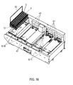
- the input carrier section 8 comprises a plurality of input carrier supports 10 (see FIG. 16 ), each of which being adapted for receiving one rack carrier 12.
- the output carrier section 9 comprises a plurality of output carrier supports 11 (see FIG. 15 or 16 ), each of which being adapted for receiving one rack carrier 12 in a fixed position.
- both the input carrier section 8 and the output carrier section 9 have a number of two carrier supports 10, 11. It, however, is to be understood that any other number of carrier supports 10, 11 can be envisaged according to the specific demands of the user, such as, but not limited to, one carrier support 10, 11 or four carrier supports 10, 11 provided in one carrier section 8, 9.
- the input carrier supports 10 and the output carrier supports 11 are arranged side by side along the first horizontal direction (x).
- an elongate tube rack 7 has a plurality of tube seats 14, each of which being adapted for holding one sample tube 5 which are serially arranged with respect to each other along the extension of the tube rack 7.
- the tube rack 7 can, e.g., be provided with five tube seats 14, however, those of skill in the art will appreciate that any other number of tube seats 14 and arrangement thereof can be envisaged according to the specific demands of the user.
- the sample tubes 5 are made of glass or plastics and can have a tubular body for receiving liquid closed on the bottom side by a rounded, e.g. hemispherical, bottom.
- the sample tubes 5 can be inserted into the tube seats 14 in an upright position.
- an elongate rack carrier 12 commonly referred to as "tray” is configured to receive a plurality of tube racks 7.
- a rack carrier 12 can receive plural tube racks 7 arranged one after the other along the extension of the rack carrier 12, with the tube seats 14 of a tube rack 7 being arranged perpendicular to the extension of the rack carrier 12.
- the tube racks 7 can be put on the rack carrier 12 in a manner to be guidable (guided) along a rack guide 13 extending along the extension of the rack carrier 12.
- the tube racks 7 are specifically adapted to be brought in guiding engagement with the rack guide 13.
- the rack guide 13 is configured as a guide rail, adapted for slidably guiding the tube racks 7.
- the rack guide 13 extends along a second direction (y), orthogonally aligned with respect to the first horizontal direction (x), with the tube seats 14 of each tube rack 7 extending along the first horizontal direction (x).
- each input carrier support 10 comprises an individual input pusher 15 for pushing tube racks 7 from a rack carrier 12 positioned on the input carrier support 10 towards and onto the transfer lane 41.
- the input pusher 15 is translatably coupled to an elongate pusher guide 18 extending along the second horizontal direction (y), such as but not limited to, a guide rail. Accordingly, the input pusher 15 can be translated along the second direction (y) guided by the pusher guide 18.
- the input pusher 15 of an input carrier support 10 is provided with an input pusher contact face 17 positioned towards tube racks 7 on a rack carrier 12 on the input carrier support 10 for pushing the tube racks 7 onto the transfer lane 41.
- each input pusher 15 has an elongate pusher plate 16 extending along the first horizontal direction (x) provided with a chamfered end portion to be used as input pusher contact face 17 for pushing tube racks 7, with the pusher plate 16 being coupled to the pusher guide 18 via a strut 19.
- Each input pusher 15 can be moved to a parking area 51 so as to provide free access to the corresponding input carrier support 10 in order to put a rack carrier 12 on the input carrier support 10 or to remove it therefrom.
- the input pushers 15 can be fixed in various stop positions as given by first engagement elements 20 relative to the second horizontal direction (y) by an input pusher fixation mechanism 52.
- the first engagement elements 20 can be engaged with second engagement elements 21 of the input pusher 15.
- the pusher guide 18 is provided with plural fixation recesses 20 as first engagement elements for inserting a fixation crotchet 21 as second engagement element 21 of the input pusher 15.
- the input pusher 15 further comprises a release mechanism 22 which can be operated for releasing the fixation of the input pusher 15.
- the release mechanism 22 is configured to pull the fixation crotchet 21 out of a fixation recess 20, in particular, against the resilient force of a resilient member.
- the input pusher 15 can be translated by means of the first tube rack transfer device 2 comprising a horizontal two-rail moving mechanism.
- a first rail 23 extends in the first horizontal direction (x) and a second rail 24 extends in the second horizontal direction (y), with the second rail 24 being translatably fixed to the first rail 23 so as to be translatable along the first rail 23.
- the first rail 23 is provided with a rail guide 25 extending along the first rail 23 for guiding the second rail 24, with the second rail 24 being engaged with the rail guide 25.
- the second rail 24 can be translated along the first rail 23.
- a first moving mechanism 26, e.g. comprising a first electric motor 27 rotatably coupled to a first belt drive 28, can be operated to automatically translate the second rail 24 along the first rail 23.
- the second rail 24 is provided with a transfer head 29, with the transfer head 29 being translatably fixed to the second rail 24 so as to be translatable along the second rail 24.
- the second rail 24 is provided with a transfer head guide 30 extending along the second rail 24 for guiding of the transfer head 29, with the transfer head 29 being engaged with the transfer head guide 30. Accordingly, the transfer head 29 can be translated along the second rail 24.
- a second moving mechanism 26, e.g. comprising a second electric motor 28 rotatably coupled to a second belt drive 33, can be operated to translate the transfer head 29 along the second rail 24. Accordingly, the transfer head 29 can be moved over a horizontal plane having components of travel in the first horizontal direction (x) and/or the second horizontal direction (y).
- the transfer head 29 is provided with various control pins for controlling movements of the tube racks 7.
- the transfer head 29 is provided with an input pusher control pin 34, adapted to be coupled with an input pusher 15 for moving of the input pusher 15 and an input pusher fixation control pin 35, adapted to be coupled with an input pusher 15 for releasing of the input pusher fixation mechanism 52 so that the input pusher 15 can be translated in the second horizontal direction (y).
- the transfer head 29 further comprises an output pusher control pin 36, adapted to be coupled with an output pusher 38 as described further below.
- the second rail 24 is provided with a transfer lane pin 37 which is linearly translatable together with the second rail 24 in the first horizontal direction (x).
- the input pusher control pin 34, the input pusher fixation control pin 35 and the transfer lane pin 37 project orthogonally (upwards) relative to the horizontal plane spanned by the first and second horizontal directions (x, y). Contrary thereto, the output pusher control pin 36 projects in the first horizontal direction (x).
- an input pusher 15 can be translated by moving the input pusher control pin 34.
- each input pusher 15 is provided with an input pusher control pin recess 39 opening in the first horizontal direction (x) so that the input pusher control pin 34 can readily be inserted by moving the transfer head 29 in the first horizontal direction (x). Accordingly, the input pusher 15 can be moved in the second horizontal direction (y) by moving the transfer head 29 in the second horizontal direction (y).
- the input pusher fixation control pin 35 can be used to release the input pusher fixation mechanism 52 so as to enable a translational movement of the input pusher 15. Specifically, by inserting the input pusher control pin 34 in the input pusher control pin recess 39, the input pusher fixation control pin 35 is simultaneously brought in contact with a turning lever 40 coupled to the release mechanism 22 in a manner to release the fixation of the input pusher 15. Stated more particularly, in one embodiment, by turning the turning lever 40 by pushing the input pusher fixation control pin 35 against the turning lever 40, the fixation of the input pusher 15 is released by pulling the fixation crotchet 21 out of a fixation recess 20, in particular, against the resilient force of a resilient element.
- the turning lever 40 can be turned back by the resilient force of the resilient element so as to insert the fixation crotchet 21 in another fixation recess 20 for fixing the input pusher 15.
- a tube rack 7 can be pushed from a rack carrier 12 on the transfer lane 41 by moving the input pusher 15 towards the transfer lane 41.
- a tube rack 7 can be translated along the transfer lane 41 by moving the transfer lane pin 37 which can be engaged with a tube rack recess 58 (see FIGS. 21 and 22 ).
- the transfer lane pin 37 is automatically brought in engagement with the tube rack recess 58 of a tube rack 7 when being pushed on the transfer lane 41 by moving the transfer head 29.
- a tube rack 7 on the transfer lane 41 can be translated in the first direction (x) by moving the transfer lane pin 37 by moving the second rail 24. Accordingly, a tube rack 7 can be transported from a rack carrier 12 of the input carrier section 8 along the first direction (x).
- a rack transport shuttle 42 for transporting tube racks 7 is coupled to the transfer lane 41 in a position between the input carrier section 8 and the output carrier section 9.
- the rack transport shuttle 42 is configured to receive a tube rack 7 from the transfer lane 41 or to supply a tube rack 7 to the transfer lane 41.
- the rack transport shuttle 42 can be moved between the transport lane 41 and the sampling area 4 in order to transport tube racks 7 to and away from the sampling area 4. Accordingly, using the rack transport shuttle 42 coupled to the transfer lane 41, tube racks 7 can be transported from the input carrier section 8 to the sampling area 4 and from the sampling area 4 to the output carrier section 9.
- each output carrier support 11 comprises an output pusher 38 for pushing tube racks 7 from the transfer lane 41 to a rack carrier 12 positioned on the output carrier support 11.
- the output pusher 38 is provided with an output pusher contact face 43 positioned towards a tube rack 7 on the transfer lane 41 in front of the output pusher 38, with the output pusher 38 being tiltable in the second horizontal direction (y) towards and away from the output carrier support 11.
- the output pusher contact face 43 can be brought in contact with a tube rack 7 positioned on the transfer lane 41 in front of the output pusher 38 so as to push the tube rack 7 onto a rack carrier 12.
- each output pusher 38 comprises a pusher mount 44 provided with an output pusher contact face 43, with the pusher mount 44 being tiltably fixed to a base 45 of the output carrier section 9.
- the output pusher 38 can be pivoted by the first tube rack transfer device 2. Specifically, the output pusher control pin 36 can be engaged with an output pusher control pin recess 46, which, as illustrated, in one embodiment, is formed by a hook, by moving the transfer head 29 in the first horizontal direction (x). Having the output pusher control pin 36 inserted into the output pusher control pin recess 46, the output pusher 38 can be tilted towards the output carrier support 11 by moving the transfer head 29 in the second horizontal direction (y). The output pusher control pin 36 can also be used to move the output pusher 38 away from the output carrier support 11.
- movement of the output pusher 38 towards the output carrier support 11 is against the resilient force of a resilient element, so that the resilient force can be used to move the output pusher 38 back if the output pusher control pin 36 is out of contact with the output pusher control pin recess 46.
- each carrier support 10, 11 comprises one or more positioning elements 47 for the correct positioning of a rack carrier 12.
- each carrier support 10, 11 comprises a number of depressions for inserting corresponding projections (not illustrated) of the rack carrier 12.
- the rack carrier 12 has a holding bow 50 for the manual transport thereof.
- each carrier support 10, 11 is provided with a sensor (not illustrated) for detecting the presence of a rack carrier 12, e.g., be detecting the holding bow 50.
- tube racks 7 can be supplied to the instrument 1 by positioning a rack carrier 12 filled with tube racks 7 on an input carrier support 10.
- the tube racks 7 supplied can be transported to the sampling area 4 via the transfer lane 41 and the rack transport shuttle 42.
- tube racks 7 can be transported from the sampling area 4 to a rack carrier 12 on an output carrier support 11 so as to remove the rack carrier 12 together with tube racks 7.
- the sampling area 4 comprises a (non-removable) rack carrier 12' provided with a plurality of carrier slots 54 arranged in two slot rows 55, each of which extending in the second horizontal direction (y) and being arranged side by side along the first horizontal direction (x).
- the sampling area 4 comprises another rack carrier 12" with a plurality of input slots 49, arranged in a row extending along the second horizontal direction (y), with each of which being adapted to support a tube rack 7 for (manually) inputting tube racks 7 to the sampling area 4. Accordingly, tube racks 7 can be directly supplied to the sampling area 4 for preferentially analyzing samples, e.g. in urgent cases.
- a first free space 56 is arranged in-between the rack carrier 12' and the input slots 49.
- a second free space 57 is arranged on the other side of the rack carrier 12'.
- tube racks 7 can be transported by the second tube rack transfer device 2' comprising a horizontal two-rail moving mechanism.
- the second tube rack transfer device 2' comprises a first rail 23' extending in the second horizontal direction (y) and a second rail 24' extending in the first horizontal direction (x), with the second rail 24' being translatably fixed to the first rail 23' so as to be translatable along the first rail 23'.
- the first rail 23' is provided with a rail guide 25' extending along the first rail 23' for guiding the second rail 24', with the second rail 24' being engaged with the rail guide 25'.
- the second rail 24' can be translated along the first rail 23'.
- a first moving mechanism 26' e.g. comprising a first electric motor 27' rotatably coupled to a first belt drive 28', can be operated to automatically translate the second rail 24' along the first rail 23'.
- the second rail 24' is provided with a transfer head 29', with the transfer head 29' being translatably fixed to the second rail 24' so as to be translatable along the second rail 24'.
- the second rail 24' is provided with a transfer head guide 30' extending along the second rail 24' for guiding of the transfer head 29', with the transfer head 29' being engaged with the transfer head guide 30'. Accordingly, the transfer head 29' can be translated along the second rail 24'.
- a second moving mechanism 26' e.g. comprising a second electric motor 28' rotatably coupled to a second belt drive 33', can be operated to translate the transfer head 29' along the second rail 24'.
- the transfer head 29' can be moved over a horizontal plane having components of travel in the first horizontal direction (x) and/or the second horizontal direction (y).
- the transfer head 29' is provided with a rack control pin 53 for controlling movements of the tube racks 7.
- the rack control pin 53 projects orthogonally relative to the horizontal plane spanned by the first and second horizontal directions (x,y).
- the rack control pin 53 can brought in engagement with a tube rack recess 58 of a tube rack 7 for moving the tube rack 7.
- the rack control pin 53 can be used analogously to the transfer lane pin 37 by directly interacting with a tube rack 7.
- the second rail 24' can be moved along the second horizontal direction (y) along the extension of the slot rows 55 of the carrier slots 54.
- the second rail 24' is provided with two rail slots 59, each of which being capable of supporting a tube rack 7 and being arranged in the first and second free spaces 56, 57, respectively.
- the rail slots 59 can be aligned with both a carrier slot 54 and an input slot 49 by moving the second rail 24' along the second horizontal direction (y).
- a tube rack 7 can readily be transported from an input slot 49 to a carrier slot 54 via the rail slot 59 arranged there-between by moving the rack control pin 53 along the second rail 24'.
- a tube rack 7 can be transported from one carrier slot 54 to another carrier slot 54 via one rail slot 59.
- the rack control pin 53 can be moved from one carrier slot 54 to another carrier slot 54 via pin holes 60. Accordingly, the rack control pin 53 can be disengaged from a tube rack 7 in a carrier slot 54 for leaving the tube rack 7 in the carrier slot 54. Furthermore, the rack control pin 53 can be engaged with a tube rack 7 in a carrier slot 54 for moving the tube rack 7 out of the carrier slot 54.
- the rack control pin 53 can be engaged with a rack 7 in the rack transport shuttle 42 to transport tube racks 7 from the sample unit 6 to the sampling area 4 and vice versa.
- a tube rack 7 can be transported from the rack transport shuttle 42 to a carrier slot 54, or vice versa, by transferring the tube rack 7 via a rail slot 59.
- a tube rack 7 can also be transported from a carrier slot 54 in one slot row 55 to another carrier slot 54 in another slot row 55, or from an input slot 49 to a carrier slot 54 via a transfer lane 41'.
- tube racks 7 can readily be transported between the sampling unit 6 and the sampling area 4 and within the sampling area 4 by using the two tube rack transfer devices 2, 2' which can have a similar construction.
- a controller 48 is setup for the automated transfer of tube racks 7 in the diagnostic instrument 1. Specifically, if a rack carrier 12 with tube racks 7 is put on an input carrier support 10 (with the input pusher 15 being in the parking area 51), the input pusher 15 is moved towards the transfer lane 41 until it gets into contact with the closest tube rack 7 on the rack carrier 12. The position of the input pusher 15 reached can be used to automatically identify the presence and number of tube racks 7 on the rack carrier 12 supplied.
- the input pusher control pin 34 is engaged with the input pusher 15 and simultaneously the input pusher fixation mechanism 52 is released by the input pusher fixation control pin 35, followed by moving the transfer head 29 towards the transfer lane 41 so as to push the first tube rack 7 (farthest away from the input pusher 15) on the transfer lane 41.
- the tube rack 7 pushed on the transfer lane 41 is automatically engaged with the transfer lane pin 37 due to the position of the transfer lane pin 37 without moving the second rail 24.
- the tube rack 7 is transported to the rack transport shuttle 42 so as to continue transport with rack transport shuttle 42.
- the rack transport shuttle 42 is moved to the sampling area 4 for transferring a tube rack 7 to the tube rack transfer device 2' for being transferred to a slot 54. Then, a tube rack 7 is transported from the sampling area 4 to the transfer lane 41 via the rack transport shuttle 42 by operating the second tube rack transfer device 2' so as to be brought in contact with the transfer lane pin 37. Now, by moving the second rail 24 along the first horizontal direction (x), the tube rack 7 is transported in a position in front of an output pusher 38. Then, the output pusher control pin 36 is engaged with the output pusher 38 so as to tilt the output pusher 38 towards a rack carrier 12 on an output carrier support 11 to push the tube rack 7 on the rack carrier 12. Furthermore, the controller 48 is setup to select a carrier slot 54 based on the availability of the carrier slot 54 and/or a travel distance to reach the carrier slot 54.
- a rack carrier 12 in the output carrier section 9 is completely filled to then be removed manually from the output carrier section 9.
- a sensor (not illustrated) arranged in correspondence with an output carrier section 9 can be used to identify a filling degree of a rack carrier 12. Furthermore, the number of tube racks 7 pushed on the rack carrier 12 can be counted.
- the instrument 1 has many advantages over the prior art.
- a major advantage is given by the fact that the instrument is simple and robust in construction by having tube rack transfer devices provided with only a few number of components.
- the transport of tube racks with respect to plural carrier sections and rack carriers, respectively, can be performed by only one movable transfer head provided with control pins which can be controlled by only two electric motors. Accordingly, the transport of tube racks can easily be controlled.
- the instrument due to a comparably low number of components, the instrument can be produced at low-cost and is suitable for long-term maintenance-free usage. As a result, samples can be processed in a highly cost-efficient manner.
Priority Applications (6)
| Application Number | Priority Date | Filing Date | Title |
|---|---|---|---|
| ES13196392T ES2882303T3 (es) | 2013-12-10 | 2013-12-10 | Dispositivo de transferencia de gradillas para tubos e instrumento de diagnóstico |
| EP13196392.8A EP2884286B1 (fr) | 2013-12-10 | 2013-12-10 | Unité de transport des supports de tubes à essais et appareil d'analyse |
| US14/561,283 US9915673B2 (en) | 2013-12-10 | 2014-12-05 | Tube rack transfer device and diagnostic instrument |
| CN201410741241.1A CN104698201B (zh) | 2013-12-10 | 2014-12-08 | 管架转移装置和诊断仪器 |
| JP2014248982A JP6454144B2 (ja) | 2013-12-10 | 2014-12-09 | チューブラック移送装置および診断機器 |
| US15/883,458 US10895581B2 (en) | 2013-12-10 | 2018-01-30 | Tube rack transfer device and diagnostic instrument |
Applications Claiming Priority (1)
| Application Number | Priority Date | Filing Date | Title |
|---|---|---|---|
| EP13196392.8A EP2884286B1 (fr) | 2013-12-10 | 2013-12-10 | Unité de transport des supports de tubes à essais et appareil d'analyse |
Publications (2)
| Publication Number | Publication Date |
|---|---|
| EP2884286A1 true EP2884286A1 (fr) | 2015-06-17 |
| EP2884286B1 EP2884286B1 (fr) | 2021-06-16 |
Family
ID=49876361
Family Applications (1)
| Application Number | Title | Priority Date | Filing Date |
|---|---|---|---|
| EP13196392.8A Active EP2884286B1 (fr) | 2013-12-10 | 2013-12-10 | Unité de transport des supports de tubes à essais et appareil d'analyse |
Country Status (5)
| Country | Link |
|---|---|
| US (2) | US9915673B2 (fr) |
| EP (1) | EP2884286B1 (fr) |
| JP (1) | JP6454144B2 (fr) |
| CN (1) | CN104698201B (fr) |
| ES (1) | ES2882303T3 (fr) |
Cited By (2)
| Publication number | Priority date | Publication date | Assignee | Title |
|---|---|---|---|---|
| EP3336555A4 (fr) * | 2015-08-12 | 2019-04-10 | Jeol Ltd. | Appareil de transport de support d'échantillons et système d'analyse automatisé |
| US11639942B2 (en) | 2015-06-22 | 2023-05-02 | Shenzhen Mindray Bio-Medical Electronics Co., Ltd. | Sample analyzer |
Families Citing this family (17)
| Publication number | Priority date | Publication date | Assignee | Title |
|---|---|---|---|---|
| WO2015157972A1 (fr) | 2014-04-17 | 2015-10-22 | 深圳迈瑞生物医疗电子股份有限公司 | Mécanisme de déplacement de plateau pour échantillons, dispositif de transport de plateau pour échantillons et dispositif d'analyse d'échantillon |
| CN108027379B (zh) | 2015-06-26 | 2021-07-23 | 雅培实验室 | 用于诊断分析设备的反应容器交换装置 |
| CN105092871A (zh) * | 2015-08-10 | 2015-11-25 | 胥凤山 | 一种生化分析仪 |
| CN105116161B (zh) * | 2015-09-22 | 2016-10-19 | 上海科华实验系统有限公司 | 轨道进出样装置 |
| CN105203785B (zh) * | 2015-10-26 | 2017-03-29 | 上海科华实验系统有限公司 | 轨道式试管进出样装置 |
| FR3048510B1 (fr) * | 2016-03-01 | 2020-01-31 | Arteion | Systeme d’analyse automatique pour diagnostic in vitro |
| US10948507B2 (en) * | 2016-11-30 | 2021-03-16 | Sysmex Corporation | Specimen transport apparatus, specimen measurement apparatus, specimen transport method, and holder |
| CN106896235B (zh) * | 2017-03-10 | 2018-12-07 | 深圳市亚辉龙生物科技股份有限公司 | 样本分析仪的进样装置和样本分析仪 |
| CN106697422A (zh) * | 2017-03-31 | 2017-05-24 | 舟山市天海机械有限公司 | 一种水果杯多通道封口输送装置 |
| EP3622301B1 (fr) * | 2017-05-10 | 2022-11-02 | Siemens Healthcare Diagnostics Inc. | Manipulateur de plateau porte-échantillons et ensemble rotation pour système d'analyse d'échantillons |
| CN109580970B (zh) * | 2017-09-29 | 2022-07-15 | 深圳市新产业生物医学工程股份有限公司 | 样本架加载系统、加载方法及化学发光检测仪 |
| CN109682981A (zh) * | 2017-10-19 | 2019-04-26 | 深圳迈瑞生物医疗电子股份有限公司 | 样本移送设备、样本分析系统及其控制方法 |
| CN110683327B (zh) * | 2018-07-04 | 2022-08-05 | 深圳迈瑞生物医疗电子股份有限公司 | 一种样本架调度机构及方法 |
| CN109570065B (zh) * | 2018-12-13 | 2021-02-09 | 湖南爱威医疗科技有限公司 | 检测卡分选装置及其分选方法 |
| CN110980246B (zh) * | 2019-12-13 | 2021-04-27 | 宋光兰 | 一种试管推送变轨系统及变轨方法 |
| JP7350189B2 (ja) | 2020-08-27 | 2023-09-25 | 株式会社日立ハイテク | 検体ラック移送装置およびそれを用いた自動分析装置 |
| CN112816723A (zh) * | 2021-04-19 | 2021-05-18 | 宁波海壹生物科技有限公司 | 一种化学发光免疫分析仪的进样出样装置 |
Citations (5)
| Publication number | Priority date | Publication date | Assignee | Title |
|---|---|---|---|---|
| EP0979999A2 (fr) * | 1998-07-14 | 2000-02-16 | Bayer Corporation | Dispositif automatique pour l'introduction et l'éjection de récipients dans une analysateur |
| US6586255B1 (en) * | 1997-07-21 | 2003-07-01 | Quest Diagnostics Incorporated | Automated centrifuge loading device |
| US7115090B2 (en) * | 2002-07-25 | 2006-10-03 | Stago Instruments | Method and device for pretreatment of samples by centrifuging |
| US20100166606A1 (en) * | 2008-12-27 | 2010-07-01 | Sysmex Corporation | Transporting apparatus and sample analyzer |
| EP2620776A1 (fr) * | 2012-01-30 | 2013-07-31 | F. Hoffmann-La Roche AG | Unité de gestion de porte-échantillons |
Family Cites Families (12)
| Publication number | Priority date | Publication date | Assignee | Title |
|---|---|---|---|---|
| US4099921A (en) * | 1977-03-28 | 1978-07-11 | Instrumentation Specialties Company | Chemical analyzer |
| DE69928644T2 (de) * | 1999-05-14 | 2006-07-27 | F. Hoffmann-La Roche Ag | Automatisches Analysesystem |
| WO2005093432A2 (fr) * | 2004-03-05 | 2005-10-06 | Beckman Coulter, Inc. | Module de transport d'echantillon pour une cellule de travail clinique a instruments multiples |
| US7850914B2 (en) * | 2004-03-05 | 2010-12-14 | Beckman Coulter, Inc. | Specimen-transport module for a multi-instrument clinical workcell |
| JP4546863B2 (ja) * | 2005-03-28 | 2010-09-22 | シスメックス株式会社 | 搬送装置 |
| JP5049769B2 (ja) * | 2007-12-25 | 2012-10-17 | 株式会社日立ハイテクノロジーズ | 自動分析装置および検体処理システム |
| EP2148206B1 (fr) * | 2008-07-25 | 2015-11-18 | F.Hoffmann-La Roche Ag | Système de laboratoire pour la manipulation de portoir de tubes d'échantillons, et élément d'alignement pour portoirs de tubes d'échantillons et ensemble recevant le plateau de portoirs |
| WO2010032628A1 (fr) | 2008-09-16 | 2010-03-25 | 株式会社 日立ハイテクノロジーズ | Dispositif d’analyse automatique et système de traitement d’échantillons |
| JP5468250B2 (ja) * | 2008-12-11 | 2014-04-09 | ベックマン コールター, インコーポレイテッド | ラック搬送システム |
| CA2761293C (fr) * | 2009-05-15 | 2015-09-22 | Gen-Probe Incorporated | Procede et appareil pour effectuer un transfert de receptacles de reaction dans un instrument pour procedures analytiques a etapes multiples |
| CN202735359U (zh) | 2012-06-28 | 2013-02-13 | 深圳市新产业生物医学工程股份有限公司 | 一种应用于化学发光领域检验设备的样本推进装置 |
| ITMI20122011A1 (it) * | 2012-11-27 | 2014-05-28 | Inpeco Ip Ltd | Apparato di deposito, conservazione e recupero automatico di campioni di materiale biologico in/da un magazzino refrigerato per mezzo di due robot statici distinti. |
-
2013
- 2013-12-10 EP EP13196392.8A patent/EP2884286B1/fr active Active
- 2013-12-10 ES ES13196392T patent/ES2882303T3/es active Active
-
2014
- 2014-12-05 US US14/561,283 patent/US9915673B2/en active Active
- 2014-12-08 CN CN201410741241.1A patent/CN104698201B/zh active Active
- 2014-12-09 JP JP2014248982A patent/JP6454144B2/ja active Active
-
2018
- 2018-01-30 US US15/883,458 patent/US10895581B2/en active Active
Patent Citations (5)
| Publication number | Priority date | Publication date | Assignee | Title |
|---|---|---|---|---|
| US6586255B1 (en) * | 1997-07-21 | 2003-07-01 | Quest Diagnostics Incorporated | Automated centrifuge loading device |
| EP0979999A2 (fr) * | 1998-07-14 | 2000-02-16 | Bayer Corporation | Dispositif automatique pour l'introduction et l'éjection de récipients dans une analysateur |
| US7115090B2 (en) * | 2002-07-25 | 2006-10-03 | Stago Instruments | Method and device for pretreatment of samples by centrifuging |
| US20100166606A1 (en) * | 2008-12-27 | 2010-07-01 | Sysmex Corporation | Transporting apparatus and sample analyzer |
| EP2620776A1 (fr) * | 2012-01-30 | 2013-07-31 | F. Hoffmann-La Roche AG | Unité de gestion de porte-échantillons |
Cited By (3)
| Publication number | Priority date | Publication date | Assignee | Title |
|---|---|---|---|---|
| US11639942B2 (en) | 2015-06-22 | 2023-05-02 | Shenzhen Mindray Bio-Medical Electronics Co., Ltd. | Sample analyzer |
| EP3336555A4 (fr) * | 2015-08-12 | 2019-04-10 | Jeol Ltd. | Appareil de transport de support d'échantillons et système d'analyse automatisé |
| US10914753B2 (en) | 2015-08-12 | 2021-02-09 | Jeol Ltd. | Sample rack conveying apparatus and automated analysis system |
Also Published As
| Publication number | Publication date |
|---|---|
| CN104698201A (zh) | 2015-06-10 |
| US10895581B2 (en) | 2021-01-19 |
| EP2884286B1 (fr) | 2021-06-16 |
| ES2882303T3 (es) | 2021-12-01 |
| JP6454144B2 (ja) | 2019-01-16 |
| US9915673B2 (en) | 2018-03-13 |
| US20150160249A1 (en) | 2015-06-11 |
| CN104698201B (zh) | 2019-01-11 |
| US20180156832A1 (en) | 2018-06-07 |
| JP2015114329A (ja) | 2015-06-22 |
Similar Documents
| Publication | Publication Date | Title |
|---|---|---|
| US10895581B2 (en) | Tube rack transfer device and diagnostic instrument | |
| JP5566484B2 (ja) | 試料試験管ラックを取り扱う研究室システム、試料試験管ラックの配列要素およびラックトレイ受承組立体 | |
| US3985507A (en) | Automatic test sample handling system | |
| EP2620776B1 (fr) | Unité de gestion de porte-échantillons | |
| US9011066B2 (en) | Coverslipping module for mounting coverslips onto specimen slides | |
| JP2008534924A (ja) | リニアラックを使用する自動化化学的又は生物学的分析装置のためのカルーセルシステム | |
| BRPI0717120B1 (pt) | aparelho, sistema e método para manuseio de tubos, em particular um aparelho de análise sanguínea automático | |
| EP2889627B1 (fr) | Appareil d'analyse d'échantillons | |
| US8865069B2 (en) | Apparatus and process for opening and closing fluid containers | |
| JP2009509136A (ja) | 自動固相マイクロ抽出(spme)サンプリング装置 | |
| JP6419540B2 (ja) | 検体測定装置および検体測定方法 | |
| EP2883667A1 (fr) | Dispositif permettant de saisir des récipients | |
| EP3312614A1 (fr) | Analyseur d'échantillon | |
| CA2270304A1 (fr) | Sous-systeme de manipulation de recipients pour un systeme d'analyse automatise de chimie clinique | |
| JP6362737B2 (ja) | 自動分析装置における液体コンテナの輸送 | |
| JP2012163334A (ja) | オートサンプラ | |
| US8262993B2 (en) | Slidable autosampler tray | |
| EP3032265B1 (fr) | Dispositif de stockage de récipients de fluide | |
| JP2021529314A (ja) | 自動分析器 | |
| CN214503654U (zh) | 样本检测装置 | |
| JPH10239322A (ja) | 自動前詰分注装置 | |
| CN117590012A (zh) | 样本加载/卸载装置、自动分析仪及其操作方法 | |
| JP2007315870A (ja) | サンプルラック供給回収装置 | |
| JP2017110973A (ja) | 流体容器の保管用の装置 | |
| JP2011007692A (ja) | ラック供給ユニット、ラック回収ユニット及びこれらを備えた自動分析装置 |
Legal Events
| Date | Code | Title | Description |
|---|---|---|---|
| PUAI | Public reference made under article 153(3) epc to a published international application that has entered the european phase |
Free format text: ORIGINAL CODE: 0009012 |
|
| 17P | Request for examination filed |
Effective date: 20131210 |
|
| AK | Designated contracting states |
Kind code of ref document: A1 Designated state(s): AL AT BE BG CH CY CZ DE DK EE ES FI FR GB GR HR HU IE IS IT LI LT LU LV MC MK MT NL NO PL PT RO RS SE SI SK SM TR |
|
| AX | Request for extension of the european patent |
Extension state: BA ME |
|
| R17P | Request for examination filed (corrected) |
Effective date: 20151217 |
|
| RBV | Designated contracting states (corrected) |
Designated state(s): AL AT BE BG CH CY CZ DE DK EE ES FI FR GB GR HR HU IE IS IT LI LT LU LV MC MK MT NL NO PL PT RO RS SE SI SK SM TR |
|
| STAA | Information on the status of an ep patent application or granted ep patent |
Free format text: STATUS: EXAMINATION IS IN PROGRESS |
|
| 17Q | First examination report despatched |
Effective date: 20190920 |
|
| GRAP | Despatch of communication of intention to grant a patent |
Free format text: ORIGINAL CODE: EPIDOSNIGR1 |
|
| STAA | Information on the status of an ep patent application or granted ep patent |
Free format text: STATUS: GRANT OF PATENT IS INTENDED |
|
| INTG | Intention to grant announced |
Effective date: 20201012 |
|
| GRAJ | Information related to disapproval of communication of intention to grant by the applicant or resumption of examination proceedings by the epo deleted |
Free format text: ORIGINAL CODE: EPIDOSDIGR1 |
|
| STAA | Information on the status of an ep patent application or granted ep patent |
Free format text: STATUS: EXAMINATION IS IN PROGRESS |
|
| GRAP | Despatch of communication of intention to grant a patent |
Free format text: ORIGINAL CODE: EPIDOSNIGR1 |
|
| STAA | Information on the status of an ep patent application or granted ep patent |
Free format text: STATUS: GRANT OF PATENT IS INTENDED |
|
| INTC | Intention to grant announced (deleted) | ||
| INTG | Intention to grant announced |
Effective date: 20210305 |
|
| GRAS | Grant fee paid |
Free format text: ORIGINAL CODE: EPIDOSNIGR3 |
|
| GRAA | (expected) grant |
Free format text: ORIGINAL CODE: 0009210 |
|
| STAA | Information on the status of an ep patent application or granted ep patent |
Free format text: STATUS: THE PATENT HAS BEEN GRANTED |
|
| AK | Designated contracting states |
Kind code of ref document: B1 Designated state(s): AL AT BE BG CH CY CZ DE DK EE ES FI FR GB GR HR HU IE IS IT LI LT LU LV MC MK MT NL NO PL PT RO RS SE SI SK SM TR |
|
| REG | Reference to a national code |
Ref country code: GB Ref legal event code: FG4D |
|
| REG | Reference to a national code |
Ref country code: CH Ref legal event code: EP |
|
| REG | Reference to a national code |
Ref country code: DE Ref legal event code: R096 Ref document number: 602013077933 Country of ref document: DE |
|
| REG | Reference to a national code |
Ref country code: AT Ref legal event code: REF Ref document number: 1402773 Country of ref document: AT Kind code of ref document: T Effective date: 20210715 |
|
| REG | Reference to a national code |
Ref country code: IE Ref legal event code: FG4D |
|
| REG | Reference to a national code |
Ref country code: LT Ref legal event code: MG9D |
|
| PG25 | Lapsed in a contracting state [announced via postgrant information from national office to epo] |
Ref country code: LT Free format text: LAPSE BECAUSE OF FAILURE TO SUBMIT A TRANSLATION OF THE DESCRIPTION OR TO PAY THE FEE WITHIN THE PRESCRIBED TIME-LIMIT Effective date: 20210616 Ref country code: FI Free format text: LAPSE BECAUSE OF FAILURE TO SUBMIT A TRANSLATION OF THE DESCRIPTION OR TO PAY THE FEE WITHIN THE PRESCRIBED TIME-LIMIT Effective date: 20210616 Ref country code: BG Free format text: LAPSE BECAUSE OF FAILURE TO SUBMIT A TRANSLATION OF THE DESCRIPTION OR TO PAY THE FEE WITHIN THE PRESCRIBED TIME-LIMIT Effective date: 20210916 Ref country code: HR Free format text: LAPSE BECAUSE OF FAILURE TO SUBMIT A TRANSLATION OF THE DESCRIPTION OR TO PAY THE FEE WITHIN THE PRESCRIBED TIME-LIMIT Effective date: 20210616 |
|
| REG | Reference to a national code |
Ref country code: AT Ref legal event code: MK05 Ref document number: 1402773 Country of ref document: AT Kind code of ref document: T Effective date: 20210616 |
|
| REG | Reference to a national code |
Ref country code: NL Ref legal event code: MP Effective date: 20210616 |
|
| PG25 | Lapsed in a contracting state [announced via postgrant information from national office to epo] |
Ref country code: NO Free format text: LAPSE BECAUSE OF FAILURE TO SUBMIT A TRANSLATION OF THE DESCRIPTION OR TO PAY THE FEE WITHIN THE PRESCRIBED TIME-LIMIT Effective date: 20210916 Ref country code: SE Free format text: LAPSE BECAUSE OF FAILURE TO SUBMIT A TRANSLATION OF THE DESCRIPTION OR TO PAY THE FEE WITHIN THE PRESCRIBED TIME-LIMIT Effective date: 20210616 Ref country code: RS Free format text: LAPSE BECAUSE OF FAILURE TO SUBMIT A TRANSLATION OF THE DESCRIPTION OR TO PAY THE FEE WITHIN THE PRESCRIBED TIME-LIMIT Effective date: 20210616 Ref country code: LV Free format text: LAPSE BECAUSE OF FAILURE TO SUBMIT A TRANSLATION OF THE DESCRIPTION OR TO PAY THE FEE WITHIN THE PRESCRIBED TIME-LIMIT Effective date: 20210616 Ref country code: GR Free format text: LAPSE BECAUSE OF FAILURE TO SUBMIT A TRANSLATION OF THE DESCRIPTION OR TO PAY THE FEE WITHIN THE PRESCRIBED TIME-LIMIT Effective date: 20210917 |
|
| REG | Reference to a national code |
Ref country code: ES Ref legal event code: FG2A Ref document number: 2882303 Country of ref document: ES Kind code of ref document: T3 Effective date: 20211201 |
|
| PG25 | Lapsed in a contracting state [announced via postgrant information from national office to epo] |
Ref country code: EE Free format text: LAPSE BECAUSE OF FAILURE TO SUBMIT A TRANSLATION OF THE DESCRIPTION OR TO PAY THE FEE WITHIN THE PRESCRIBED TIME-LIMIT Effective date: 20210616 Ref country code: CZ Free format text: LAPSE BECAUSE OF FAILURE TO SUBMIT A TRANSLATION OF THE DESCRIPTION OR TO PAY THE FEE WITHIN THE PRESCRIBED TIME-LIMIT Effective date: 20210616 Ref country code: SK Free format text: LAPSE BECAUSE OF FAILURE TO SUBMIT A TRANSLATION OF THE DESCRIPTION OR TO PAY THE FEE WITHIN THE PRESCRIBED TIME-LIMIT Effective date: 20210616 Ref country code: SM Free format text: LAPSE BECAUSE OF FAILURE TO SUBMIT A TRANSLATION OF THE DESCRIPTION OR TO PAY THE FEE WITHIN THE PRESCRIBED TIME-LIMIT Effective date: 20210616 Ref country code: AT Free format text: LAPSE BECAUSE OF FAILURE TO SUBMIT A TRANSLATION OF THE DESCRIPTION OR TO PAY THE FEE WITHIN THE PRESCRIBED TIME-LIMIT Effective date: 20210616 Ref country code: PT Free format text: LAPSE BECAUSE OF FAILURE TO SUBMIT A TRANSLATION OF THE DESCRIPTION OR TO PAY THE FEE WITHIN THE PRESCRIBED TIME-LIMIT Effective date: 20211018 Ref country code: RO Free format text: LAPSE BECAUSE OF FAILURE TO SUBMIT A TRANSLATION OF THE DESCRIPTION OR TO PAY THE FEE WITHIN THE PRESCRIBED TIME-LIMIT Effective date: 20210616 Ref country code: NL Free format text: LAPSE BECAUSE OF FAILURE TO SUBMIT A TRANSLATION OF THE DESCRIPTION OR TO PAY THE FEE WITHIN THE PRESCRIBED TIME-LIMIT Effective date: 20210616 |
|
| PG25 | Lapsed in a contracting state [announced via postgrant information from national office to epo] |
Ref country code: PL Free format text: LAPSE BECAUSE OF FAILURE TO SUBMIT A TRANSLATION OF THE DESCRIPTION OR TO PAY THE FEE WITHIN THE PRESCRIBED TIME-LIMIT Effective date: 20210616 |
|
| REG | Reference to a national code |
Ref country code: DE Ref legal event code: R097 Ref document number: 602013077933 Country of ref document: DE |
|
| PLBE | No opposition filed within time limit |
Free format text: ORIGINAL CODE: 0009261 |
|
| STAA | Information on the status of an ep patent application or granted ep patent |
Free format text: STATUS: NO OPPOSITION FILED WITHIN TIME LIMIT |
|
| PG25 | Lapsed in a contracting state [announced via postgrant information from national office to epo] |
Ref country code: DK Free format text: LAPSE BECAUSE OF FAILURE TO SUBMIT A TRANSLATION OF THE DESCRIPTION OR TO PAY THE FEE WITHIN THE PRESCRIBED TIME-LIMIT Effective date: 20210616 |
|
| 26N | No opposition filed |
Effective date: 20220317 |
|
| PG25 | Lapsed in a contracting state [announced via postgrant information from national office to epo] |
Ref country code: AL Free format text: LAPSE BECAUSE OF FAILURE TO SUBMIT A TRANSLATION OF THE DESCRIPTION OR TO PAY THE FEE WITHIN THE PRESCRIBED TIME-LIMIT Effective date: 20210616 |
|
| PG25 | Lapsed in a contracting state [announced via postgrant information from national office to epo] |
Ref country code: MC Free format text: LAPSE BECAUSE OF FAILURE TO SUBMIT A TRANSLATION OF THE DESCRIPTION OR TO PAY THE FEE WITHIN THE PRESCRIBED TIME-LIMIT Effective date: 20210616 |
|
| REG | Reference to a national code |
Ref country code: BE Ref legal event code: MM Effective date: 20211231 |
|
| PG25 | Lapsed in a contracting state [announced via postgrant information from national office to epo] |
Ref country code: LU Free format text: LAPSE BECAUSE OF NON-PAYMENT OF DUE FEES Effective date: 20211210 Ref country code: IE Free format text: LAPSE BECAUSE OF NON-PAYMENT OF DUE FEES Effective date: 20211210 |
|
| PG25 | Lapsed in a contracting state [announced via postgrant information from national office to epo] |
Ref country code: BE Free format text: LAPSE BECAUSE OF NON-PAYMENT OF DUE FEES Effective date: 20211231 |
|
| PG25 | Lapsed in a contracting state [announced via postgrant information from national office to epo] |
Ref country code: IT Free format text: LAPSE BECAUSE OF NON-PAYMENT OF DUE FEES Effective date: 20211210 |
|
| PGFP | Annual fee paid to national office [announced via postgrant information from national office to epo] |
Ref country code: ES Payment date: 20230109 Year of fee payment: 10 Ref country code: CH Payment date: 20230101 Year of fee payment: 10 |
|
| PG25 | Lapsed in a contracting state [announced via postgrant information from national office to epo] |
Ref country code: HU Free format text: LAPSE BECAUSE OF FAILURE TO SUBMIT A TRANSLATION OF THE DESCRIPTION OR TO PAY THE FEE WITHIN THE PRESCRIBED TIME-LIMIT; INVALID AB INITIO Effective date: 20131210 |
|
| PG25 | Lapsed in a contracting state [announced via postgrant information from national office to epo] |
Ref country code: CY Free format text: LAPSE BECAUSE OF FAILURE TO SUBMIT A TRANSLATION OF THE DESCRIPTION OR TO PAY THE FEE WITHIN THE PRESCRIBED TIME-LIMIT Effective date: 20210616 |
|
| PGFP | Annual fee paid to national office [announced via postgrant information from national office to epo] |
Ref country code: GB Payment date: 20231121 Year of fee payment: 11 |
|
| PGFP | Annual fee paid to national office [announced via postgrant information from national office to epo] |
Ref country code: FR Payment date: 20231122 Year of fee payment: 11 Ref country code: DE Payment date: 20231121 Year of fee payment: 11 |