EP2884070A1 - Systems and methods for cooling a diesel exhaust fluid dosing module of an agricultural vehicle - Google Patents
Systems and methods for cooling a diesel exhaust fluid dosing module of an agricultural vehicle Download PDFInfo
- Publication number
- EP2884070A1 EP2884070A1 EP14197254.7A EP14197254A EP2884070A1 EP 2884070 A1 EP2884070 A1 EP 2884070A1 EP 14197254 A EP14197254 A EP 14197254A EP 2884070 A1 EP2884070 A1 EP 2884070A1
- Authority
- EP
- European Patent Office
- Prior art keywords
- conduit
- dosing module
- cooling
- cooling fluid
- engine
- Prior art date
- Legal status (The legal status is an assumption and is not a legal conclusion. Google has not performed a legal analysis and makes no representation as to the accuracy of the status listed.)
- Withdrawn
Links
Images


Classifications
-
- F—MECHANICAL ENGINEERING; LIGHTING; HEATING; WEAPONS; BLASTING
- F01—MACHINES OR ENGINES IN GENERAL; ENGINE PLANTS IN GENERAL; STEAM ENGINES
- F01N—GAS-FLOW SILENCERS OR EXHAUST APPARATUS FOR MACHINES OR ENGINES IN GENERAL; GAS-FLOW SILENCERS OR EXHAUST APPARATUS FOR INTERNAL-COMBUSTION ENGINES
- F01N3/00—Exhaust or silencing apparatus having means for purifying, rendering innocuous, or otherwise treating exhaust
- F01N3/08—Exhaust or silencing apparatus having means for purifying, rendering innocuous, or otherwise treating exhaust for rendering innocuous
- F01N3/10—Exhaust or silencing apparatus having means for purifying, rendering innocuous, or otherwise treating exhaust for rendering innocuous by thermal or catalytic conversion of noxious components of exhaust
- F01N3/18—Exhaust or silencing apparatus having means for purifying, rendering innocuous, or otherwise treating exhaust for rendering innocuous by thermal or catalytic conversion of noxious components of exhaust characterised by methods of operation; Control
- F01N3/20—Exhaust or silencing apparatus having means for purifying, rendering innocuous, or otherwise treating exhaust for rendering innocuous by thermal or catalytic conversion of noxious components of exhaust characterised by methods of operation; Control specially adapted for catalytic conversion
- F01N3/2006—Periodically heating or cooling catalytic reactors, e.g. at cold starting or overheating
- F01N3/2046—Periodically cooling catalytic reactors
-
- F—MECHANICAL ENGINEERING; LIGHTING; HEATING; WEAPONS; BLASTING
- F01—MACHINES OR ENGINES IN GENERAL; ENGINE PLANTS IN GENERAL; STEAM ENGINES
- F01N—GAS-FLOW SILENCERS OR EXHAUST APPARATUS FOR MACHINES OR ENGINES IN GENERAL; GAS-FLOW SILENCERS OR EXHAUST APPARATUS FOR INTERNAL-COMBUSTION ENGINES
- F01N3/00—Exhaust or silencing apparatus having means for purifying, rendering innocuous, or otherwise treating exhaust
- F01N3/08—Exhaust or silencing apparatus having means for purifying, rendering innocuous, or otherwise treating exhaust for rendering innocuous
- F01N3/10—Exhaust or silencing apparatus having means for purifying, rendering innocuous, or otherwise treating exhaust for rendering innocuous by thermal or catalytic conversion of noxious components of exhaust
- F01N3/18—Exhaust or silencing apparatus having means for purifying, rendering innocuous, or otherwise treating exhaust for rendering innocuous by thermal or catalytic conversion of noxious components of exhaust characterised by methods of operation; Control
- F01N3/20—Exhaust or silencing apparatus having means for purifying, rendering innocuous, or otherwise treating exhaust for rendering innocuous by thermal or catalytic conversion of noxious components of exhaust characterised by methods of operation; Control specially adapted for catalytic conversion
- F01N3/206—Adding periodically or continuously substances to exhaust gases for promoting purification, e.g. catalytic material in liquid form, NOx reducing agents
- F01N3/2066—Selective catalytic reduction [SCR]
-
- F—MECHANICAL ENGINEERING; LIGHTING; HEATING; WEAPONS; BLASTING
- F01—MACHINES OR ENGINES IN GENERAL; ENGINE PLANTS IN GENERAL; STEAM ENGINES
- F01N—GAS-FLOW SILENCERS OR EXHAUST APPARATUS FOR MACHINES OR ENGINES IN GENERAL; GAS-FLOW SILENCERS OR EXHAUST APPARATUS FOR INTERNAL-COMBUSTION ENGINES
- F01N2260/00—Exhaust treating devices having provisions not otherwise provided for
- F01N2260/02—Exhaust treating devices having provisions not otherwise provided for for cooling the device
- F01N2260/024—Exhaust treating devices having provisions not otherwise provided for for cooling the device using a liquid
-
- F—MECHANICAL ENGINEERING; LIGHTING; HEATING; WEAPONS; BLASTING
- F01—MACHINES OR ENGINES IN GENERAL; ENGINE PLANTS IN GENERAL; STEAM ENGINES
- F01N—GAS-FLOW SILENCERS OR EXHAUST APPARATUS FOR MACHINES OR ENGINES IN GENERAL; GAS-FLOW SILENCERS OR EXHAUST APPARATUS FOR INTERNAL-COMBUSTION ENGINES
- F01N2590/00—Exhaust or silencing apparatus adapted to particular use, e.g. for military applications, airplanes, submarines
- F01N2590/08—Exhaust or silencing apparatus adapted to particular use, e.g. for military applications, airplanes, submarines for heavy duty applications, e.g. trucks, buses, tractors, locomotives
-
- F—MECHANICAL ENGINEERING; LIGHTING; HEATING; WEAPONS; BLASTING
- F01—MACHINES OR ENGINES IN GENERAL; ENGINE PLANTS IN GENERAL; STEAM ENGINES
- F01N—GAS-FLOW SILENCERS OR EXHAUST APPARATUS FOR MACHINES OR ENGINES IN GENERAL; GAS-FLOW SILENCERS OR EXHAUST APPARATUS FOR INTERNAL-COMBUSTION ENGINES
- F01N2610/00—Adding substances to exhaust gases
- F01N2610/02—Adding substances to exhaust gases the substance being ammonia or urea
-
- F—MECHANICAL ENGINEERING; LIGHTING; HEATING; WEAPONS; BLASTING
- F01—MACHINES OR ENGINES IN GENERAL; ENGINE PLANTS IN GENERAL; STEAM ENGINES
- F01N—GAS-FLOW SILENCERS OR EXHAUST APPARATUS FOR MACHINES OR ENGINES IN GENERAL; GAS-FLOW SILENCERS OR EXHAUST APPARATUS FOR INTERNAL-COMBUSTION ENGINES
- F01N2610/00—Adding substances to exhaust gases
- F01N2610/11—Adding substances to exhaust gases the substance or part of the dosing system being cooled
-
- F—MECHANICAL ENGINEERING; LIGHTING; HEATING; WEAPONS; BLASTING
- F01—MACHINES OR ENGINES IN GENERAL; ENGINE PLANTS IN GENERAL; STEAM ENGINES
- F01N—GAS-FLOW SILENCERS OR EXHAUST APPARATUS FOR MACHINES OR ENGINES IN GENERAL; GAS-FLOW SILENCERS OR EXHAUST APPARATUS FOR INTERNAL-COMBUSTION ENGINES
- F01N2610/00—Adding substances to exhaust gases
- F01N2610/14—Arrangements for the supply of substances, e.g. conduits
- F01N2610/1493—Purging the reducing agent out of the conduits or nozzle
-
- F—MECHANICAL ENGINEERING; LIGHTING; HEATING; WEAPONS; BLASTING
- F01—MACHINES OR ENGINES IN GENERAL; ENGINE PLANTS IN GENERAL; STEAM ENGINES
- F01P—COOLING OF MACHINES OR ENGINES IN GENERAL; COOLING OF INTERNAL-COMBUSTION ENGINES
- F01P2060/00—Cooling circuits using auxiliaries
- F01P2060/10—Fuel manifold
-
- F—MECHANICAL ENGINEERING; LIGHTING; HEATING; WEAPONS; BLASTING
- F01—MACHINES OR ENGINES IN GENERAL; ENGINE PLANTS IN GENERAL; STEAM ENGINES
- F01P—COOLING OF MACHINES OR ENGINES IN GENERAL; COOLING OF INTERNAL-COMBUSTION ENGINES
- F01P2060/00—Cooling circuits using auxiliaries
- F01P2060/16—Outlet manifold
-
- F—MECHANICAL ENGINEERING; LIGHTING; HEATING; WEAPONS; BLASTING
- F01—MACHINES OR ENGINES IN GENERAL; ENGINE PLANTS IN GENERAL; STEAM ENGINES
- F01P—COOLING OF MACHINES OR ENGINES IN GENERAL; COOLING OF INTERNAL-COMBUSTION ENGINES
- F01P2060/00—Cooling circuits using auxiliaries
- F01P2060/18—Heater
-
- Y—GENERAL TAGGING OF NEW TECHNOLOGICAL DEVELOPMENTS; GENERAL TAGGING OF CROSS-SECTIONAL TECHNOLOGIES SPANNING OVER SEVERAL SECTIONS OF THE IPC; TECHNICAL SUBJECTS COVERED BY FORMER USPC CROSS-REFERENCE ART COLLECTIONS [XRACs] AND DIGESTS
- Y02—TECHNOLOGIES OR APPLICATIONS FOR MITIGATION OR ADAPTATION AGAINST CLIMATE CHANGE
- Y02A—TECHNOLOGIES FOR ADAPTATION TO CLIMATE CHANGE
- Y02A50/00—TECHNOLOGIES FOR ADAPTATION TO CLIMATE CHANGE in human health protection, e.g. against extreme weather
- Y02A50/20—Air quality improvement or preservation, e.g. vehicle emission control or emission reduction by using catalytic converters
-
- Y—GENERAL TAGGING OF NEW TECHNOLOGICAL DEVELOPMENTS; GENERAL TAGGING OF CROSS-SECTIONAL TECHNOLOGIES SPANNING OVER SEVERAL SECTIONS OF THE IPC; TECHNICAL SUBJECTS COVERED BY FORMER USPC CROSS-REFERENCE ART COLLECTIONS [XRACs] AND DIGESTS
- Y02—TECHNOLOGIES OR APPLICATIONS FOR MITIGATION OR ADAPTATION AGAINST CLIMATE CHANGE
- Y02T—CLIMATE CHANGE MITIGATION TECHNOLOGIES RELATED TO TRANSPORTATION
- Y02T10/00—Road transport of goods or passengers
- Y02T10/10—Internal combustion engine [ICE] based vehicles
- Y02T10/12—Improving ICE efficiencies
Definitions
- the invention relates generally to agricultural vehicles and, more particularly, to systems and methods for cooling a diesel exhaust fluid (DEF) dosing module of an agricultural vehicle.
- DEF diesel exhaust fluid
- Exhaust after treatment systems typically direct an exhaust stream toward a diesel oxidation catalyst (DOC).
- DOC diesel oxidation catalyst
- the DOC may contain a particulate filter to remove fines and other solid material from the exhaust stream.
- an oxidation reaction may convert the hydrocarbons and carbon monoxide in the exhaust stream into carbon dioxide and water, among other compounds.
- the exhaust stream may be directed toward a dosing module.
- the dosing module may contain an injection port for directing a DEF into the exhaust stream.
- the DEF may be a urea solution that decomposes into ammonia in the exhaust stream.
- the exhaust stream may be directed toward a selective catalytic reduction reactor (SCR). In the SCR, the ammonia and some exhaust stream components may be converted to nitrogen and water.
- SCR selective catalytic reduction reactor
- exhaust after treatment systems may reduce NOX emissions from diesel exhaust streams
- manufacturers may have difficulties finding suitable locations to mount the additional equipment. This may be especially true in agricultural equipment where space under the hood is limited.
- additional design constraints e.g., temperature, pressure, etc. may reduce the number of suitable locations for the exhaust after treatment system.
- the exhaust after treatment system also utilizes support equipment.
- the dosing module may use cooling at its injection port because of exhaust stream temperatures and/or to reduce crystallization of the DEF.
- a cooling fluid from the engine cooling system may be used to cool the dosing module.
- an additional reservoir may be used to store cooling fluid for cooling the dosing module after the engine is shut off.
- the additional reservoir may be plastic to reduce cost and weight, but may also use shielding to protect the plastic material from the heat of the engine and exhaust stream.
- the reservoir may also have a vent to prevent vapor lock in the cooling lines.
- An extra vent in the system may lead to significant modifications to the engine cooling system.
- the reservoir may utilize an additional pump to enable circulation after the engine is turned off.
- additional reservoirs, heat shielding, pumps, and vents may not be practical. Accordingly, there exists a need for a dosing module cooling system that can use cooling fluid from the engine cooling system without auxiliary equipment.
- an agricultural vehicle in one embodiment, includes an exhaust system.
- the exhaust system also includes a dosing module having a fluid inlet and a fluid outlet. Additionally, the exhaust system includes a first conduit coupled directly between the fluid inlet and an engine cooling system of the agricultural vehicle. The first conduit is configured to hold a cooling fluid.
- the exhaust system also includes a second conduit coupled directly between the fluid outlet and the engine cooling system and is configured to hold the cooling fluid. The cooling fluid is configured to flow from the first and second conduits into the engine cooling system after an engine of the agricultural vehicle is turned off.
- a method for cooling a dosing module includes directing a cooling fluid through a first conduit.
- the first conduit is coupled directly between a fluid inlet of the dosing module and an engine cooling system.
- the method also includes directing the cooling fluid from the first conduit into the fluid inlet of the dosing module.
- the method includes directing the cooling fluid from a fluid outlet of the dosing module and through a second conduit.
- the second conduit is coupled directly between the fluid outlet of the dosing module and the engine cooling system.
- the method also includes maintaining a volume of cooling fluid in the first conduit and the second conduit after a pump of the engine cooling system is shut off. The pump is configured to move the cooling fluid.
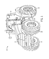
- FIG. 1 illustrates an exemplary agricultural vehicle 10 that may employ an exhaust after treatment system with a dosing module cooling system.
- the agricultural vehicle 10 may be any type of tractor, off-road vehicle, work vehicle, or any other suitable vehicle that utilizes an exhaust after treatment system to meet regulatory emission requirements.
- the vehicle 10 illustrated has a body 12 that will typically house an engine, transmission, and power train (not separately shown). Further, the agricultural vehicle 10 has a cabin 14 where an operator may sit or stand to operate the vehicle 10.
- the vehicle 10 has two front wheels 16 and two rear wheels 18 (only one is shown) that rotate to move the vehicle 10 in the depicted embodiment. However, more wheels 16, 18 may be present.
- the vehicle 10 may have 4, 6, 8, or any number of front wheels 16 and/or back wheels 18.
- the vehicle 10 is maneuvered using a steering wheel 20 that causes the wheels 16 to turn.
- the wheels 16 are coupled together by an axle 22 so that both wheels 16 may be rotated together.
- the vehicle 10 has an exhaust 24 that emits byproducts of combustion within the engine.
- the agricultural vehicle 10 may include an exhaust after treatment system with a dosing module cooling system.
- the exhaust after treatment system may be utilized to reduce mono-nitrogen oxides (NOX), particulates, or greenhouse gases in the engine exhaust stream.
- the dosing module cooling system may continue to provide cooling to the exhaust after treatment system after the engine is shut off.
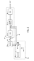
- FIG. 2 is a block diagram of an exhaust after treatment system 34 fluidly coupled to an engine 36 and an engine cooling system 38.
- the engine 36 may be a diesel engine that directs an exhaust stream 40 to the exhaust after treatment system 34 through an exhaust conduit 42.
- the exhaust stream 40 may be a product of the combustion and/or operation of the engine 36. Because the combustion process may produce heat, the engine 36 may be coupled to and cooled by the engine cooling system 38.
- the engine cooling system 38 may be mounted away from the engine 36 or in some embodiments may be mounted directly in front of the engine 36.
- the engine 36 may have ports configured to receive a cooling fluid 44 (e.g., water, glycol, etc.) from the engine cooling system 38.
- a cooling fluid 44 e.g., water, glycol, etc.
- the engine cooling system 38 may include a radiator 46, a thermostat 48, and a pump 50. Cooling fluid 44 may be directed toward the engine 36 by the pump 50. That is, the pump 50 may move pressurized cooling fluid 44 to the engine 36. There, the cooling fluid 44 may absorb heat from the engine 36 (e.g., receive energy from the engine 36) and return to the engine cooling system 38. The cooling fluid 44 may enter the radiator 46 when it returns from the engine 36. As the cooling fluid 44 moves through the radiator 46, air may flow over the radiator 46 thereby cooling the cooling fluid 44. Then, the cooling fluid 44 may flow past the thermostat 48 and into the pump 50 to recirculate through the system. As may be appreciated, the engine cooling system 38 may include additional components not shown (e.g., valves, sensors, etc.).
- the engine cooling system 38 may also be configured to direct the cooling fluid 44 toward the exhaust after treatment system 34.
- the exhaust after treatment system 34 may include a diesel oxidation catalyst (DOC) 52, a dosing module 54, and a selective catalytic reduction reactor (SCR) 56.
- DOC diesel oxidation catalyst
- SCR selective catalytic reduction reactor
- the DOC 52 may include a particulate filter to remove fines or other solid material in the exhaust stream 40.
- the exhaust stream 40 may pass through the DOC 52.
- the components of the exhaust stream 40 e.g., carbon monoxide, gaseous hydrocarbons, etc.
- the filters may remove fines and other solid materials from the exhaust stream 40.
- no DOC 52 is included in the exhaust after treatment system 34.
- the filter may be installed separately from the DOC 52, in an exhaust after treatment system 34 that does not include the DOC 52, or not at all.
- the exhaust stream 40 is directed from the DOC 52 toward the dosing module 54.
- a diesel exhaust fluid may be injected into the exhaust stream 40 using an injector of the dosing module 54 as the exhaust stream 40 passes through the dosing module 54.
- DEF diesel exhaust fluid
- the hydrolysis of DEF in the exhaust stream 40 may produce ammonia.
- the exhaust stream 40 may flow toward the SCR 56 where an additional reaction converts NOX in the exhaust stream 40 to nitrogen and water before the exhaust stream 40 is vented to the atmosphere. Accordingly, emissions from the engine 36 may be reduced by injecting DEF into the exhaust stream 40 and utilizing the SCR 56.
- FIG. 3 is a schematic drawing of an embodiment of a dosing module cooling system 68.
- the dosing module cooling system 68 includes a first conduit 70 and a second conduit 72 configured to direct cooling fluid 44 to and/or from the dosing module 54.
- the conduits 70, 72 may be made from a rigid tubing material.
- the conduits 70, 72 may be made from metals (e.g., carbon steel, stainless steel, etc.), polymers (e.g., PVC, etc.), and/or the like.
- the conduits 70, 72 may be made from a flexible material.
- the conduits 70, 72 may be made from polymer tubing (nylon, PVC, etc.), gooseneck metal tubing (e.g., steel), and/or the like. Moreover, the conduits 70, 72 may be made from a combination of both rigid and flexible tubing material. Additionally, the first conduit 70 and the second conduit 72 may be made from different materials.
- the first conduit 70 may be configured to direct cold cooling fluid 44 (e.g., cooling fluid 44 cooled in the radiator 42) from the engine cooling system 38 to the dosing module 54 and, therefore, may be made from a material with a lower thermal conductivity than the second conduit 72 to block heat transfer to/from the cooling fluid 44 as it flows to the dosing module 54.
- the second conduit 72 may be configured to return the cooling fluid 44 to the engine cooling system 38 after the cooling fluid 44 has passed through the dosing module 54 and, therefore, may be made from a material with a higher thermal conductivity to facilitate heat transfer as the cooling fluid 44 flows back to the engine cooling system 38.
- the first conduit 70 and the second conduit 72 may be circuitously routed.
- the first conduit 70 and the second conduit 72 may have many generally parallel sections.
- the first conduit 70 and the second conduit 72 may be generally "S" shaped or sigmoidal. That is, the first conduit 70 and the second conduit 72 may each have multiple bends (e.g., the conduit routing will change direction) in order to fit within a confined space within the body 12 of the agricultural vehicle 10.
- a first section 74 may be generally parallel to a second section 76 and a third section 78.
- a fourth section 80 may be generally parallel to a fifth section 82 and a sixth section 84.
- circuitous routing may contain the first and second conduits 70, 72 (sections) that are generally perpendicular to one another.
- the first section 74 may be generally perpendicular to the fourth section 80, the fifth section 82, and the sixth section 84.
- conduits 70, 72 with circuitous routing leads to a greater volume of fluid being directed toward the dosing module 54 than if conduit was routed to the engine cooling system 38 along the shortest possible path.
- a first length 86 is shorter than the sum of a second length 88 and a third length 90.
- the conduits 70, 72 being routed circuitously along the second length 88 and the third length 90 will have a greater overall length, which directly corresponds to a greater volume, than if the conduits 70, 72 were routed along the first length 86 (e.g., the shortest possible path).
- circuitous routing enables a substantial amount of the cooling fluid 44 to travel to the dosing module 54 in a relatively confined space.
- the dosing module cooling system 68 may be secured within the body 12 of the agricultural vehicle 10 as required by design constraints to reduce potential stress points and/or to minimize vibration.
- the circuitous routing of the conduits 70, 72 enables cooling of the dosing module 54 after the engine 36 is shut off without the use of an additional cooling fluid 44 tank because a sufficient volume (e.g., at least equal to an additional tank that could occupy the same volume of space) will remain in the conduits 70, 72 after the engine 36 is shut off.
- the volume of the conduits 70, 72 can be equal to an additional tank because of the added length of the circuitous routing.
- the conduits 70, 72 may be self purging as described in more detail below.
- first conduit 70, the second conduit 72, or both may be finned tubes.
- the conduits 70, 72 may have radial extensions that increase the surface area of the conduits 70, 72 and facilitate a larger amount of heat transfer with the surrounding atmosphere.
- the conduits 70, 72 may be "twisted tubes" designed to maximize turbulent flow in the conduits 70, 72 and therefore increase heat transfer.
- many additional methods could be applied to increase the heat transfer of the conduits 70, 72 without substantially changing the volume of the conduits 70, 72.
- the dosing module cooling system 68 may be substantially mounted above the engine cooling system 38 (e.g., above an expansion tank associated with the engine cooling system 38). That is, a volume of the first conduit 70 and a volume of the second conduit 72 will be at a higher elevation than the engine cooling system 38. As a result, when the engine 36 is shut off and the pump 50 is no longer moving the cooling fluid 44, cooling fluid 44 will remain in the conduits 70, 72 of the dosing module cooling system 68 for a period of time. The volume of the cooling fluid 44 that remains in the conduits 70, 72 functions like an additional reservoir and enables the dosing module 54 to be cooled even when the engine cooling system 38 is not circulating the cooling fluid 44. As will be described in more detail below, the dosing module cooling system 68 may continue to circulate cooling fluid 44 through the dosing module 54 after the engine 36 is shut off via a thermosiphon.
- FIG. 4 is a cross-sectional view of the dosing module 54 in accordance with one embodiment of the present disclosure.
- the dosing module 54 includes an injector 92, a DEF tank 94, and additional associated components (e.g., thermostats, metering valves, pumps, sensors, etc.).
- the injector 92 protrudes through a wall of the dosing module 54 and extends into the exhaust stream 40.
- DEF may be injected into the exhaust stream 40 using the injector 92 as the exhaust stream 40 passes through the dosing module 54.
- the hydrolysis of DEF in the exhaust stream 40 may produce ammonia.
- the injector 92 may spray the DEF evenly into the exhaust stream 40 and reduce the occurrence of deposits contacting and/or forming on the dosing module 54 walls. However, in some embodiments, the injector 92 may only extend as far as the wall thickness of the dosing module 54. In some embodiments, the injector 92 may be equipped with an atomizing or misting nozzle configured to inject the DEF in small droplets that more readily evaporate and/or mix in the exhaust stream 40. Moreover, depending on design conditions, the injector 92 may be configured to inject the DEF in a downstream direction (e.g., in the direction of the exhaust stream 40 flow toward the SCR 56). However, the DEF may also be injected in the upstream direction.
- the dosing module 54 may be made from a variety of materials.
- the dosing module 54 may be made from a metal (e.g., steel, alloys, etc.) to withstand high temperatures and/or environmental contaminants from fluids/gases. However, some parts of the dosing module 54 may not be made of metals.
- the DEF tank 94 may be made from a polymeric material. Because the dosing module 54 may be exposed to high temperatures of the exhaust stream 40, the dosing module 54 includes a first cooling channel 96 and a second cooling channel 98. The first cooling channel 96 and the second cooling channel 98 may be connected.
- the cooling channels 96, 98 are configured to surround and/or cool the injector 92 as well as the other components of the dosing module 54.
- the cooling channels 96, 98 may form a single annulus that surrounds the injector 92.
- the dosing module 54 may have an annulus that receives the injector 92. The annulus may be larger than the diameter of the injector 92, leaving space for cooling fluid 44 to flow around the injector 92.
- the injector 92 and dosing module 54 may be formed together as a single piece.
- the cooling channels 96, 98 may be embedded in, or pass through, the injector 92.
- the cooling channels 96, 98 are fluidly coupled to the first conduit 70 and the second conduit 72. That is, the first conduit 70 is coupled to the first cooling channel 96 at a cooling fluid inlet 100. Similarly, the second conduit 72 is coupled to the second cooling channel 98 at a cooling fluid outlet 102.
- the first cooling channel 96 may be configured to receive the cooling fluid 44 from the engine cooling system 38 via the first conduit 70.
- the cooling fluid 44 may flow from the engine cooling system 38 through the first conduit 70 into the first cooling channel 96 and then into the second cooling channel 98. Then, the cooling fluid 44 may flow through the second cooling channel 98 to the second conduit 72 and return to the engine cooling system 38.
- the cooling fluid 44 may absorb heat from the exhaust stream 40. That is, the cooling fluid 44 may be at a lower temperature than the exhaust stream 40 and increase in temperature the longer it interacts with the exhaust stream 40.
- the cooling fluid 44 may be cooler in the first cooling channel 96 than in the second cooling channel 98 if the cooling fluid 44 is flowing from the first cooling channel 96 into the second cooling channel 98.
- cooling fluid 44 may be in a cool region 104 before it enters the dosing module 54 and in a heated region 106 as it flows through the dosing module 54. Additionally, the cooling fluid 44 may re-enter the cool region 104 after it leaves the dosing module 54. While the cooling fluid 44 is noted as flowing from the first cooling channel 96 to the second cooling channel 98, it should be noted that in some instances the cooling fluid 44 may flow from the second cooling channel 98 to the first cooling channel 96.
- thermosiphon that may circulate the cooling fluid 44 through the dosing module 54 in accordance with an embodiment of the disclosure is presented in FIGS. 5 and 6 .
- the cooling fluid 44 may enter the dosing module 54 through the cooling fluid inlet 100 via the first conduit 70 fluidly coupled to the first cooling channel 96.
- the cooling fluid 44 may be in the cool region 104.
- the heat of the exhaust stream 40 is not acting on the cooling fluid 44.
- the cooling fluid 44 may enter the heated region 106.
- the cooling fluid 44 may absorb heat and increase in temperature compared to the cooling fluid 44 in the cool region 104.
- the density of the cooling fluid 44 may decrease.
- the cooling fluid 44 in the heated region 106 may begin to flow or migrate out of the heated region 106 and be replaced by the cooling fluid 44 from the cool region 104.
- a second volume 110 of heated cooling fluid 44 may move out of the heated region 106 through the second cooling channel 98 and be replaced by a first volume 108 of cooler cooling fluid 44 from the cool region 104 via the first cooling channel 96.
- the first volume 108 of cooling fluid 44 from the cool region 104 may continue to enter the heated region 106 until the second volume 110 of cooling fluid 44 in the heated region 106 is substantially replaced by the first volume 108 of cooling fluid 44 from the cool region 104.
- cooler cooling fluid 44 will replace the heated cooling fluid 44 as long as there is a sufficient thermal gradient to cause the circulation of the cooling fluid 44.
- the process of circulating the cooling fluid 44 through the dosing module 54 via thermosiphon may continue as long as there is a sufficient temperature gradient between the cooling fluid 44 in the cool region 104 and the cooling fluid 44 in the heated region 106.
- the cooling fluid 44 that was previously in the heated region 106 may sufficiently cool after it enters the cool region 104 to create a large enough temperature gradient between it and the cooling fluid 44 that replaced it in the heated region 106. Therefore, returning to the example above, the second volume 110 of the cooling fluid 44 may sufficiently cool to replace the first volume 108 of cooling fluid in the heated region 106. This process may continue until the dosing module 54 reaches an ambient temperature or the cooling fluid 44 in the first conduit 70 and the second conduit 72 has drained back into the engine cooling system 38.
- FIG. 7 is a flowchart of one embodiment of a method 112 for cooling the dosing module 54.
- the cooling fluid 44 may be directed through the first conduit 70 (block 114).
- the first conduit 70 may be coupled directly between the cooling fluid inlet 100 of the dosing module 54 and the engine cooling system 38.
- the first conduit 70 may direct the cooling fluid 44 into the cooling fluid inlet 100 of the dosing module 54 (block 116).
- the cooling fluid 44 may exit the dosing module 54 through the cooling fluid outlet 102 and enter the second conduit 72 (block 118).
- the second conduit 72 may be coupled directly between the cooling fluid outlet 102 of the dosing module 54 and the engine cooling system 38.
- the operation of the pump 50 determines how cooling the dosing module 54 proceeds.
- the pump 50 may be on, the cooling fluid 44 will be directed back to the engine cooling system 38 (block 122). However, if the pump 50 is off, the volumes 108, 110 of the cooling fluid 44 may be maintained in the first conduit 70, the second conduit 72, and the dosing module 54 (block 124). As may be appreciated, the pump 50 may be configured to move the cooling fluid 44 from the cooling system 38 through the dosing module 54.
Landscapes
- Chemical & Material Sciences (AREA)
- Engineering & Computer Science (AREA)
- Chemical Kinetics & Catalysis (AREA)
- Health & Medical Sciences (AREA)
- Toxicology (AREA)
- Combustion & Propulsion (AREA)
- Mechanical Engineering (AREA)
- General Engineering & Computer Science (AREA)
- Exhaust Gas After Treatment (AREA)
Abstract
Description
- The invention relates generally to agricultural vehicles and, more particularly, to systems and methods for cooling a diesel exhaust fluid (DEF) dosing module of an agricultural vehicle.
- Emission regulations have lead engine manufacturers and aftermarket suppliers to install exhaust after treatment systems to meet the increasingly stringent requirements. Often, these systems direct exhaust gases through a series of reactions to reduce particulate matter and mono-nitrogen oxide (NOX) emissions in the exhaust stream. Moreover, because the treatment is done after combustion, existing equipment may be retro fit to include the exhaust after treatment systems.
- Exhaust after treatment systems typically direct an exhaust stream toward a diesel oxidation catalyst (DOC). The DOC may contain a particulate filter to remove fines and other solid material from the exhaust stream. As the exhaust stream flows over the catalyst, an oxidation reaction may convert the hydrocarbons and carbon monoxide in the exhaust stream into carbon dioxide and water, among other compounds. Next, the exhaust stream may be directed toward a dosing module. The dosing module may contain an injection port for directing a DEF into the exhaust stream. The DEF may be a urea solution that decomposes into ammonia in the exhaust stream. Then, the exhaust stream may be directed toward a selective catalytic reduction reactor (SCR). In the SCR, the ammonia and some exhaust stream components may be converted to nitrogen and water. By using the exhaust after treatment system, emissions may be reduced to meet regulatory requirements.
- While exhaust after treatment systems may reduce NOX emissions from diesel exhaust streams, manufacturers may have difficulties finding suitable locations to mount the additional equipment. This may be especially true in agricultural equipment where space under the hood is limited. Moreover, additional design constraints (e.g., temperature, pressure, etc.) may reduce the number of suitable locations for the exhaust after treatment system.
- In some configurations, the exhaust after treatment system also utilizes support equipment. For example, the dosing module may use cooling at its injection port because of exhaust stream temperatures and/or to reduce crystallization of the DEF. Specifically, a cooling fluid from the engine cooling system may be used to cool the dosing module. However, because the cooling fluid flows from the engine cooling system when the engine is running (e.g., the engine supplies power to a pump), an additional reservoir may be used to store cooling fluid for cooling the dosing module after the engine is shut off. The additional reservoir may be plastic to reduce cost and weight, but may also use shielding to protect the plastic material from the heat of the engine and exhaust stream. Additionally, if the reservoir is mounted above the engine cooling fluid system, it may also have a vent to prevent vapor lock in the cooling lines. An extra vent in the system may lead to significant modifications to the engine cooling system. Furthermore, the reservoir may utilize an additional pump to enable circulation after the engine is turned off. However, because of the limited space under the hood, additional reservoirs, heat shielding, pumps, and vents may not be practical. Accordingly, there exists a need for a dosing module cooling system that can use cooling fluid from the engine cooling system without auxiliary equipment.
- In one embodiment, an agricultural vehicle includes an exhaust system. The exhaust system also includes a dosing module having a fluid inlet and a fluid outlet. Additionally, the exhaust system includes a first conduit coupled directly between the fluid inlet and an engine cooling system of the agricultural vehicle. The first conduit is configured to hold a cooling fluid. The exhaust system also includes a second conduit coupled directly between the fluid outlet and the engine cooling system and is configured to hold the cooling fluid. The cooling fluid is configured to flow from the first and second conduits into the engine cooling system after an engine of the agricultural vehicle is turned off.
- In a further embodiment, a method for cooling a dosing module is provided. The method includes directing a cooling fluid through a first conduit. The first conduit is coupled directly between a fluid inlet of the dosing module and an engine cooling system. The method also includes directing the cooling fluid from the first conduit into the fluid inlet of the dosing module. The method includes directing the cooling fluid from a fluid outlet of the dosing module and through a second conduit. The second conduit is coupled directly between the fluid outlet of the dosing module and the engine cooling system. The method also includes maintaining a volume of cooling fluid in the first conduit and the second conduit after a pump of the engine cooling system is shut off. The pump is configured to move the cooling fluid.
- These and other features, aspects, and advantages of the present invention will become better understood when the following detailed description is read with reference to the accompanying drawings in which like characters represent like parts throughout the drawings, wherein:
-
FIG. 1 is a perspective view of an embodiment of an agricultural vehicle that may employ a dosing module cooling system in accordance with the present disclosure; -
FIG. 2 is a block diagram of an embodiment of a diesel exhaust after treatment system in accordance with the present disclosure; -
FIG. 3 is a schematic drawing of an embodiment of a dosing module cooling system in accordance with the present disclosure; -
FIG. 4 is a cross-sectional side view of a dosing module utilizing a dosing module cooling system in accordance with the present disclosure; -
FIG. 5 is a cross-sectional side view of a dosing module utilizing a dosing module cooling system with a thermal siphon circulating a cooling fluid in accordance with the present disclosure; -
FIG. 6 is a cross-sectional side view of a dosing module utilizing a dosing module cooling system after a thermal siphon has replaced a volume of cooling fluid in accordance with the present disclosure; and -
FIG. 7 is a flow chart of an embodiment of a method for cooling a dosing module after an agricultural engine is shut off and utilizing a dosing module cooling system in accordance with the present disclosure. -
FIG. 1 illustrates an exemplaryagricultural vehicle 10 that may employ an exhaust after treatment system with a dosing module cooling system. In certain embodiments, theagricultural vehicle 10 may be any type of tractor, off-road vehicle, work vehicle, or any other suitable vehicle that utilizes an exhaust after treatment system to meet regulatory emission requirements. Thevehicle 10 illustrated has abody 12 that will typically house an engine, transmission, and power train (not separately shown). Further, theagricultural vehicle 10 has acabin 14 where an operator may sit or stand to operate thevehicle 10. Thevehicle 10 has twofront wheels 16 and two rear wheels 18 (only one is shown) that rotate to move thevehicle 10 in the depicted embodiment. However,more wheels vehicle 10 may have 4, 6, 8, or any number offront wheels 16 and/orback wheels 18. As may be appreciated, thevehicle 10 is maneuvered using asteering wheel 20 that causes thewheels 16 to turn. Thewheels 16 are coupled together by anaxle 22 so that bothwheels 16 may be rotated together. Furthermore, thevehicle 10 has anexhaust 24 that emits byproducts of combustion within the engine. Theagricultural vehicle 10 may include an exhaust after treatment system with a dosing module cooling system. The exhaust after treatment system may be utilized to reduce mono-nitrogen oxides (NOX), particulates, or greenhouse gases in the engine exhaust stream. Moreover, the dosing module cooling system may continue to provide cooling to the exhaust after treatment system after the engine is shut off. -
FIG. 2 is a block diagram of an exhaust aftertreatment system 34 fluidly coupled to anengine 36 and an engine cooling system 38. Theengine 36 may be a diesel engine that directs anexhaust stream 40 to the exhaust aftertreatment system 34 through anexhaust conduit 42. Theexhaust stream 40 may be a product of the combustion and/or operation of theengine 36. Because the combustion process may produce heat, theengine 36 may be coupled to and cooled by the engine cooling system 38. The engine cooling system 38 may be mounted away from theengine 36 or in some embodiments may be mounted directly in front of theengine 36. Moreover, theengine 36 may have ports configured to receive a cooling fluid 44 (e.g., water, glycol, etc.) from the engine cooling system 38. - In some embodiments, the engine cooling system 38 may include a
radiator 46, athermostat 48, and apump 50. Coolingfluid 44 may be directed toward theengine 36 by thepump 50. That is, thepump 50 may move pressurized coolingfluid 44 to theengine 36. There, the coolingfluid 44 may absorb heat from the engine 36 (e.g., receive energy from the engine 36) and return to the engine cooling system 38. The coolingfluid 44 may enter theradiator 46 when it returns from theengine 36. As the coolingfluid 44 moves through theradiator 46, air may flow over theradiator 46 thereby cooling the coolingfluid 44. Then, the coolingfluid 44 may flow past thethermostat 48 and into thepump 50 to recirculate through the system. As may be appreciated, the engine cooling system 38 may include additional components not shown (e.g., valves, sensors, etc.). - The engine cooling system 38 may also be configured to direct the cooling
fluid 44 toward the exhaust aftertreatment system 34. The exhaust aftertreatment system 34 may include a diesel oxidation catalyst (DOC) 52, adosing module 54, and a selective catalytic reduction reactor (SCR) 56. In certain embodiments, theDOC 52 may include a particulate filter to remove fines or other solid material in theexhaust stream 40. - As the
exhaust stream 40 leaves theengine 36 and is directed through the exhaust aftertreatment system 34 it may pass through theDOC 52. In theDOC 52, the components of the exhaust stream 40 (e.g., carbon monoxide, gaseous hydrocarbons, etc.) may react with theDOC 52 and oxidize to form carbon dioxide and water. Additionally, a filter may remove fines and other solid materials from theexhaust stream 40. In some embodiments, noDOC 52 is included in the exhaust aftertreatment system 34. Moreover, the filter may be installed separately from theDOC 52, in an exhaust aftertreatment system 34 that does not include theDOC 52, or not at all. Theexhaust stream 40 is directed from theDOC 52 toward thedosing module 54. A diesel exhaust fluid (DEF) may be injected into theexhaust stream 40 using an injector of thedosing module 54 as theexhaust stream 40 passes through thedosing module 54. As may be appreciated, the hydrolysis of DEF in theexhaust stream 40 may produce ammonia. From thedosing module 54 theexhaust stream 40 may flow toward theSCR 56 where an additional reaction converts NOX in theexhaust stream 40 to nitrogen and water before theexhaust stream 40 is vented to the atmosphere. Accordingly, emissions from theengine 36 may be reduced by injecting DEF into theexhaust stream 40 and utilizing theSCR 56. -
FIG. 3 is a schematic drawing of an embodiment of a dosingmodule cooling system 68. The dosingmodule cooling system 68 includes afirst conduit 70 and asecond conduit 72 configured to direct coolingfluid 44 to and/or from thedosing module 54. In some embodiments, theconduits conduits conduits conduits conduits first conduit 70 and thesecond conduit 72 may be made from different materials. For example, thefirst conduit 70 may be configured to direct cold cooling fluid 44 (e.g., coolingfluid 44 cooled in the radiator 42) from the engine cooling system 38 to thedosing module 54 and, therefore, may be made from a material with a lower thermal conductivity than thesecond conduit 72 to block heat transfer to/from the coolingfluid 44 as it flows to thedosing module 54. In contrast, thesecond conduit 72 may be configured to return the coolingfluid 44 to the engine cooling system 38 after the coolingfluid 44 has passed through thedosing module 54 and, therefore, may be made from a material with a higher thermal conductivity to facilitate heat transfer as the coolingfluid 44 flows back to the engine cooling system 38. - The
first conduit 70 and thesecond conduit 72 may be circuitously routed. In other words, thefirst conduit 70 and thesecond conduit 72 may have many generally parallel sections. For example, thefirst conduit 70 and thesecond conduit 72 may be generally "S" shaped or sigmoidal. That is, thefirst conduit 70 and thesecond conduit 72 may each have multiple bends (e.g., the conduit routing will change direction) in order to fit within a confined space within thebody 12 of theagricultural vehicle 10. For example, a first section 74 may be generally parallel to asecond section 76 and athird section 78. Moreover, afourth section 80 may be generally parallel to afifth section 82 and asixth section 84. Furthermore, the circuitous routing may contain the first andsecond conduits 70, 72 (sections) that are generally perpendicular to one another. For example, the first section 74 may be generally perpendicular to thefourth section 80, thefifth section 82, and thesixth section 84. - As may be appreciated by one skilled in the art, using the
conduits dosing module 54 than if conduit was routed to the engine cooling system 38 along the shortest possible path. For example, afirst length 86 is shorter than the sum of asecond length 88 and athird length 90. Accordingly, theconduits second length 88 and thethird length 90 will have a greater overall length, which directly corresponds to a greater volume, than if theconduits fluid 44 to travel to thedosing module 54 in a relatively confined space. The dosingmodule cooling system 68 may be secured within thebody 12 of theagricultural vehicle 10 as required by design constraints to reduce potential stress points and/or to minimize vibration. - Additionally, the circuitous routing of the
conduits dosing module 54 after theengine 36 is shut off without the use of anadditional cooling fluid 44 tank because a sufficient volume (e.g., at least equal to an additional tank that could occupy the same volume of space) will remain in theconduits engine 36 is shut off. In other words, the volume of theconduits conduits - Additional methods may be employed to further increase the amount of cooling provided to the
dosing module 54. For example, thefirst conduit 70, thesecond conduit 72, or both may be finned tubes. In other words, theconduits conduits conduits conduits conduits conduits - In some embodiments, the dosing
module cooling system 68 may be substantially mounted above the engine cooling system 38 (e.g., above an expansion tank associated with the engine cooling system 38). That is, a volume of thefirst conduit 70 and a volume of thesecond conduit 72 will be at a higher elevation than the engine cooling system 38. As a result, when theengine 36 is shut off and thepump 50 is no longer moving the coolingfluid 44, coolingfluid 44 will remain in theconduits module cooling system 68 for a period of time. The volume of the coolingfluid 44 that remains in theconduits dosing module 54 to be cooled even when the engine cooling system 38 is not circulating the coolingfluid 44. As will be described in more detail below, the dosingmodule cooling system 68 may continue to circulate coolingfluid 44 through thedosing module 54 after theengine 36 is shut off via a thermosiphon. -
FIG. 4 is a cross-sectional view of thedosing module 54 in accordance with one embodiment of the present disclosure. Thedosing module 54 includes aninjector 92, aDEF tank 94, and additional associated components (e.g., thermostats, metering valves, pumps, sensors, etc.). Theinjector 92 protrudes through a wall of thedosing module 54 and extends into theexhaust stream 40. DEF may be injected into theexhaust stream 40 using theinjector 92 as theexhaust stream 40 passes through thedosing module 54. The hydrolysis of DEF in theexhaust stream 40 may produce ammonia. By extending into theexhaust stream 40, theinjector 92 may spray the DEF evenly into theexhaust stream 40 and reduce the occurrence of deposits contacting and/or forming on thedosing module 54 walls. However, in some embodiments, theinjector 92 may only extend as far as the wall thickness of thedosing module 54. In some embodiments, theinjector 92 may be equipped with an atomizing or misting nozzle configured to inject the DEF in small droplets that more readily evaporate and/or mix in theexhaust stream 40. Moreover, depending on design conditions, theinjector 92 may be configured to inject the DEF in a downstream direction (e.g., in the direction of theexhaust stream 40 flow toward the SCR 56). However, the DEF may also be injected in the upstream direction. - The
dosing module 54 may be made from a variety of materials. For example, thedosing module 54 may be made from a metal (e.g., steel, alloys, etc.) to withstand high temperatures and/or environmental contaminants from fluids/gases. However, some parts of thedosing module 54 may not be made of metals. For example, theDEF tank 94 may be made from a polymeric material. Because thedosing module 54 may be exposed to high temperatures of theexhaust stream 40, thedosing module 54 includes afirst cooling channel 96 and asecond cooling channel 98. Thefirst cooling channel 96 and thesecond cooling channel 98 may be connected. In certain embodiments, the coolingchannels injector 92 as well as the other components of thedosing module 54. Also, in some embodiments, the coolingchannels injector 92. For example, thedosing module 54 may have an annulus that receives theinjector 92. The annulus may be larger than the diameter of theinjector 92, leaving space for coolingfluid 44 to flow around theinjector 92. Furthermore, in some embodiments theinjector 92 anddosing module 54 may be formed together as a single piece. Moreover, the coolingchannels injector 92. As may be appreciated by one skilled in the art, the location, size, and number of thecooling channels channels first conduit 70 and thesecond conduit 72. That is, thefirst conduit 70 is coupled to thefirst cooling channel 96 at a coolingfluid inlet 100. Similarly, thesecond conduit 72 is coupled to thesecond cooling channel 98 at a coolingfluid outlet 102. - The
first cooling channel 96 may be configured to receive the coolingfluid 44 from the engine cooling system 38 via thefirst conduit 70. In some embodiments, the coolingfluid 44 may flow from the engine cooling system 38 through thefirst conduit 70 into thefirst cooling channel 96 and then into thesecond cooling channel 98. Then, the coolingfluid 44 may flow through thesecond cooling channel 98 to thesecond conduit 72 and return to the engine cooling system 38. As the coolingfluid 44 circulates through thedosing module 54, it may absorb heat from theexhaust stream 40. That is, the coolingfluid 44 may be at a lower temperature than theexhaust stream 40 and increase in temperature the longer it interacts with theexhaust stream 40. Therefore, the coolingfluid 44 may be cooler in thefirst cooling channel 96 than in thesecond cooling channel 98 if the coolingfluid 44 is flowing from thefirst cooling channel 96 into thesecond cooling channel 98. In other words, coolingfluid 44 may be in acool region 104 before it enters thedosing module 54 and in aheated region 106 as it flows through thedosing module 54. Additionally, the coolingfluid 44 may re-enter thecool region 104 after it leaves thedosing module 54. While the coolingfluid 44 is noted as flowing from thefirst cooling channel 96 to thesecond cooling channel 98, it should be noted that in some instances the coolingfluid 44 may flow from thesecond cooling channel 98 to thefirst cooling channel 96. - An illustration of the thermosiphon that may circulate the cooling
fluid 44 through thedosing module 54 in accordance with an embodiment of the disclosure is presented inFIGS. 5 and6 . As discussed above, the coolingfluid 44 may enter thedosing module 54 through the coolingfluid inlet 100 via thefirst conduit 70 fluidly coupled to thefirst cooling channel 96. Before entering thedosing module 54, the coolingfluid 44 may be in thecool region 104. As such, the heat of theexhaust stream 40 is not acting on the coolingfluid 44. However, once exposed to the heat of theexhaust stream 40 the coolingfluid 44 may enter theheated region 106. In theheated region 106, the coolingfluid 44 may absorb heat and increase in temperature compared to the coolingfluid 44 in thecool region 104. As the temperature of the coolingfluid 44 in theheated region 106 increases, the density of the coolingfluid 44 may decrease. As a result, the coolingfluid 44 in theheated region 106 may begin to flow or migrate out of theheated region 106 and be replaced by the coolingfluid 44 from thecool region 104. - As shown in
FIG. 5 , asecond volume 110 ofheated cooling fluid 44 may move out of theheated region 106 through thesecond cooling channel 98 and be replaced by afirst volume 108 ofcooler cooling fluid 44 from thecool region 104 via thefirst cooling channel 96. Moreover, as illustrated inFIG. 6 , as thesecond volume 110 ofheated cooling fluid 44 continues to leave theheated region 106, due to having a lower density than thefirst volume 108 of coolingfluid 44 in thecool region 104, thefirst volume 108 of cooling fluid 44 from thecool region 104 may continue to enter theheated region 106 until thesecond volume 110 of coolingfluid 44 in theheated region 106 is substantially replaced by thefirst volume 108 of cooling fluid 44 from thecool region 104. In other words,cooler cooling fluid 44 will replace theheated cooling fluid 44 as long as there is a sufficient thermal gradient to cause the circulation of the coolingfluid 44. - The process of circulating the cooling
fluid 44 through thedosing module 54 via thermosiphon may continue as long as there is a sufficient temperature gradient between the coolingfluid 44 in thecool region 104 and the coolingfluid 44 in theheated region 106. For example, the coolingfluid 44 that was previously in theheated region 106 may sufficiently cool after it enters thecool region 104 to create a large enough temperature gradient between it and the coolingfluid 44 that replaced it in theheated region 106. Therefore, returning to the example above, thesecond volume 110 of the coolingfluid 44 may sufficiently cool to replace thefirst volume 108 of cooling fluid in theheated region 106. This process may continue until thedosing module 54 reaches an ambient temperature or the coolingfluid 44 in thefirst conduit 70 and thesecond conduit 72 has drained back into the engine cooling system 38. -
FIG. 7 is a flowchart of one embodiment of amethod 112 for cooling thedosing module 54. The coolingfluid 44 may be directed through the first conduit 70 (block 114). Thefirst conduit 70 may be coupled directly between the coolingfluid inlet 100 of thedosing module 54 and the engine cooling system 38. Thefirst conduit 70 may direct the coolingfluid 44 into the coolingfluid inlet 100 of the dosing module 54 (block 116). The coolingfluid 44 may exit thedosing module 54 through the coolingfluid outlet 102 and enter the second conduit 72 (block 118). Thesecond conduit 72 may be coupled directly between the coolingfluid outlet 102 of thedosing module 54 and the engine cooling system 38. Atblock 120, the operation of thepump 50 determines how cooling thedosing module 54 proceeds. If thepump 50 is on, the coolingfluid 44 will be directed back to the engine cooling system 38 (block 122). However, if thepump 50 is off, thevolumes fluid 44 may be maintained in thefirst conduit 70, thesecond conduit 72, and the dosing module 54 (block 124). As may be appreciated, thepump 50 may be configured to move the coolingfluid 44 from the cooling system 38 through thedosing module 54. - While only certain features of the invention have been illustrated and described herein, many modifications and changes will occur to those skilled in the art. It is, therefore, to be understood that the appended claims are intended to cover all such modifications and changes as fall within the true spirit of the invention.
Claims (14)
- An agricultural vehicle (10) comprising an exhaust system (24) comprising:- a dosing module (54) having a fluid inlet and a fluid outlet;- a first conduit (70) coupled directly between the fluid inlet and an engine cooling system (38) of the agricultural vehicle, wherein the first conduit (70) is configured to hold a cooling fluid (44); and- a second conduit (72) coupled directly between the fluid outlet and the engine cooling system (38) and configured to hold the cooling fluid (44), wherein the cooling fluid (44) is configured to flow from the first and second conduits (70, 72) into the engine cooling system (38) after an engine (36) of the agricultural vehicle (10) is turned off.
- The agricultural vehicle (10) of claim 1, wherein a volume of the first conduit (70), a volume of the second conduit (72), or some combination thereof is configured to provide a volume of the cooling fluid (44) to the dosing module (54) after the engine (36) of the agricultural vehicle (10) is turned off.
- The agricultural vehicle (10) of claim 1, wherein at least one of the first conduit and the second conduit (70, 72) includes multiple parallel conduit portions.
- The agricultural vehicle (10) of claim 1, wherein both the first conduit and the second conduit (70, 72) include multiple parallel conduit portions.
- The agricultural vehicle (10) of claim 1, wherein at least one of the first conduit and the second conduits (70, 72) comprises finned-tubes.
- The agricultural vehicle (10) of claim 1, wherein the first conduit and the second conduit (70, 72) are self purging.
- The agricultural vehicle (10) of claim 1, wherein at least one of the first conduit and the second conduit (70, 72) is configured to supply cooling fluid (44) to the dosing module (54) after the engine (36) of the agricultural vehicle (10) is turned off.
- The agricultural vehicle (10) of claim 1, wherein at least one of the first conduit and the second conduit (70, 72) is configured to direct a first volume of the cooling fluid (44) from the dosing module (54) toward the engine cooling system (38) after the cooling fluid (44) is heated by the dosing module (58).
- The agricultural vehicle (10) of claim 8, wherein the at least one of the first conduit and the second conduit (70, 72) is configured to replace the first volume of cooling fluid (44) removed from the dosing module (54) with a second volume of cooling fluid (44).
- A method (112) of cooling a dosing module (54), comprising:- directing a cooling fluid through a first conduit (114), wherein the first conduit is coupled directly between a fluid inlet of the dosing module and an engine cooling system;- directing the cooling fluid from the first conduit into the fluid inlet of the dosing module (116);- directing the cooling fluid from a fluid outlet of the dosing module and through a second conduit (118), wherein the second conduit is coupled directly between the fluid outlet of the dosing module and the engine cooling system (122); and- maintaining a volume of cooling fluid in the first conduit and the second conduit after a pump of the engine cooling system is shut off (124), wherein the pump is configured to move the cooling fluid.
- The method of claim 10, wherein the volume of cooling fluid (44) in the first conduit (70) and the second conduit (70) is sufficient to cool the dosing module (54) to approximately an ambient temperature.
- The method of claim 10, wherein the volume of cooling fluid (44) in the first conduit (70) and the second conduit (72) is configured to flow through the dosing module (54) after the pump (50) is shut off via a thermosiphon.
- The method of claim 10, wherein the first conduit (70) and the second conduit (72) are configured to direct the cooling fluid (44) to the engine cooling system (38) after the dosing module (54) reaches approximately an ambient temperature.
- The method of claim 10, wherein the cooling fluid (44) is supplied by the engine cooling system (38).
Applications Claiming Priority (1)
| Application Number | Priority Date | Filing Date | Title |
|---|---|---|---|
| US14/105,754 US9091193B2 (en) | 2013-12-13 | 2013-12-13 | Systems and methods for cooling a diesel exhaust fluid dosing module of an agricultural vehicle |
Publications (1)
| Publication Number | Publication Date |
|---|---|
| EP2884070A1 true EP2884070A1 (en) | 2015-06-17 |
Family
ID=52021079
Family Applications (1)
| Application Number | Title | Priority Date | Filing Date |
|---|---|---|---|
| EP14197254.7A Withdrawn EP2884070A1 (en) | 2013-12-13 | 2014-12-10 | Systems and methods for cooling a diesel exhaust fluid dosing module of an agricultural vehicle |
Country Status (4)
| Country | Link |
|---|---|
| US (1) | US9091193B2 (en) |
| EP (1) | EP2884070A1 (en) |
| CN (1) | CN104712406B (en) |
| BR (1) | BR102014031388A2 (en) |
Cited By (2)
| Publication number | Priority date | Publication date | Assignee | Title |
|---|---|---|---|---|
| EP3135876A1 (en) * | 2015-08-25 | 2017-03-01 | CLAAS Tractor S.A.S. | Device for aftertreatment of exhaust gas |
| US12241397B2 (en) | 2019-10-31 | 2025-03-04 | Agco International Gmbh | Exhaust after treatment cooling system |
Families Citing this family (3)
| Publication number | Priority date | Publication date | Assignee | Title |
|---|---|---|---|---|
| JP6217408B2 (en) * | 2014-01-24 | 2017-10-25 | コベルコ建機株式会社 | Exhaust treatment device for construction machine and construction machine |
| US12152521B2 (en) | 2020-01-22 | 2024-11-26 | Cnh Industrial America Llc | System for cooling a diesel exhaust fluid |
| KR20250008947A (en) | 2022-06-17 | 2025-01-16 | 커민스 에미션 솔루션스 인코포레이티드 | Exhaust gas duct assembly |
Citations (6)
| Publication number | Priority date | Publication date | Assignee | Title |
|---|---|---|---|---|
| JPH0296212A (en) * | 1988-09-30 | 1990-04-09 | Nec Corp | Position input device |
| EP1192337A1 (en) * | 1999-04-28 | 2002-04-03 | Siemens Aktiengesellschaft | Valve seat device for a metering valve of an exhaust treatment station |
| EP1797292A1 (en) * | 2004-09-28 | 2007-06-20 | Robert Bosch Gmbh | Dosing device, and internal combustion engine comprising a dosing device |
| WO2008040363A2 (en) * | 2006-10-05 | 2008-04-10 | Grundfos Nonox A/S | Nozzel temperature control |
| WO2013081275A1 (en) * | 2011-11-30 | 2013-06-06 | 아이스파이프 주식회사 | Heat dissipation apparatus for vehicles |
| WO2013130386A1 (en) * | 2012-02-27 | 2013-09-06 | Caterpillar Inc. | Mounting assembly for a reductant injector |
Family Cites Families (19)
| Publication number | Priority date | Publication date | Assignee | Title |
|---|---|---|---|---|
| JPH063354B2 (en) | 1987-06-23 | 1994-01-12 | アクトロニクス株式会社 | Loop type thin tube heat pipe |
| DE19609306A1 (en) | 1995-03-23 | 1996-09-26 | Volkswagen Ag | Exhaust system for IC engine |
| JP3468254B2 (en) * | 1995-10-03 | 2003-11-17 | 三菱ふそうトラック・バス株式会社 | Diesel engine exhaust purification system |
| DE19806265C5 (en) | 1998-02-16 | 2004-07-22 | Siemens Ag | dosing |
| DE19927246A1 (en) | 1999-06-15 | 2000-12-28 | Emitec Emissionstechnologie | Exhaust system for an internal combustion engine of a motor vehicle |
| US20060053774A1 (en) | 2004-09-15 | 2006-03-16 | Kabasin Daniel F | Exhaust treatment system and methods using the same |
| US7861517B2 (en) | 2005-11-09 | 2011-01-04 | Delphi Technologies, Inc. | Method and system for controlling catalyst temperature |
| EP2060758B1 (en) | 2006-07-12 | 2010-10-13 | Delphi Technologies Holding S.à.r.l. | Insulated Reagent Dosing Device |
| US8261542B2 (en) | 2008-09-03 | 2012-09-11 | General Electric Company | System, method, and device for locomotive exhaust gas recirculation cooling and catalyst heating |
| DE102008052988B4 (en) | 2008-10-23 | 2012-09-27 | Continental Automotive Gmbh | Method and apparatus for controlling exhaust aftertreatment |
| US8424286B2 (en) | 2009-09-11 | 2013-04-23 | Ford Global Technologies, Llc | Vehicle relocatable exhaust system components |
| US20110079003A1 (en) * | 2009-10-05 | 2011-04-07 | Caterpillar Inc. | Reductant nozzle indentation mount |
| EP2354485A1 (en) | 2010-01-13 | 2011-08-10 | Delphi Technologies Holding S.à.r.l. | Exhaust system for compression-ignition engine |
| GB2480465A (en) | 2010-05-19 | 2011-11-23 | Gm Global Tech Operations Inc | Method of controlling injection of diesel exhaust fluid |
| US8888017B2 (en) | 2010-09-23 | 2014-11-18 | Cummins Inc. | System, method, and apparatus for delivering highly atomized diesel exhaust fluid to an exhaust aftertreatment system |
| US8720189B2 (en) | 2011-01-26 | 2014-05-13 | GM Global Technology Operations LLC | Apparatus and method for onboard performance monitoring of oxidation catalyst |
| US8689854B2 (en) | 2011-02-22 | 2014-04-08 | Deere & Company | Decomposition conduit fabrication method |
| US20130000281A1 (en) | 2011-06-30 | 2013-01-03 | Caterpillar Inc. | Def pump mounted to tank |
| US9103600B2 (en) * | 2012-12-21 | 2015-08-11 | Caterpillar Inc. | Injector cooling apparatus and method |
-
2013
- 2013-12-13 US US14/105,754 patent/US9091193B2/en active Active
-
2014
- 2014-12-05 CN CN201410737188.8A patent/CN104712406B/en active Active
- 2014-12-10 EP EP14197254.7A patent/EP2884070A1/en not_active Withdrawn
- 2014-12-15 BR BR102014031388A patent/BR102014031388A2/en not_active Application Discontinuation
Patent Citations (6)
| Publication number | Priority date | Publication date | Assignee | Title |
|---|---|---|---|---|
| JPH0296212A (en) * | 1988-09-30 | 1990-04-09 | Nec Corp | Position input device |
| EP1192337A1 (en) * | 1999-04-28 | 2002-04-03 | Siemens Aktiengesellschaft | Valve seat device for a metering valve of an exhaust treatment station |
| EP1797292A1 (en) * | 2004-09-28 | 2007-06-20 | Robert Bosch Gmbh | Dosing device, and internal combustion engine comprising a dosing device |
| WO2008040363A2 (en) * | 2006-10-05 | 2008-04-10 | Grundfos Nonox A/S | Nozzel temperature control |
| WO2013081275A1 (en) * | 2011-11-30 | 2013-06-06 | 아이스파이프 주식회사 | Heat dissipation apparatus for vehicles |
| WO2013130386A1 (en) * | 2012-02-27 | 2013-09-06 | Caterpillar Inc. | Mounting assembly for a reductant injector |
Cited By (2)
| Publication number | Priority date | Publication date | Assignee | Title |
|---|---|---|---|---|
| EP3135876A1 (en) * | 2015-08-25 | 2017-03-01 | CLAAS Tractor S.A.S. | Device for aftertreatment of exhaust gas |
| US12241397B2 (en) | 2019-10-31 | 2025-03-04 | Agco International Gmbh | Exhaust after treatment cooling system |
Also Published As
| Publication number | Publication date |
|---|---|
| US9091193B2 (en) | 2015-07-28 |
| BR102014031388A2 (en) | 2017-05-09 |
| CN104712406A (en) | 2015-06-17 |
| CN104712406B (en) | 2019-01-22 |
| US20150167527A1 (en) | 2015-06-18 |
Similar Documents
| Publication | Publication Date | Title |
|---|---|---|
| US9091193B2 (en) | Systems and methods for cooling a diesel exhaust fluid dosing module of an agricultural vehicle | |
| EP2268905B1 (en) | Vehicle exhaust treatment systems | |
| US9656210B2 (en) | Internal combustion engine | |
| EP2761148B1 (en) | Arrangement for introducing a liquid medium into exhaust gases from a combustion engine | |
| US20110243818A1 (en) | Temperature control circuit for scr urea system | |
| US20200023312A1 (en) | Producing ammonium carbamate and reducing nitrogen oxides | |
| CN204851396U (en) | A cooling system for having more among cylinder internal combustion engine's back processing unit | |
| US9267410B2 (en) | Injector cooling apparatus | |
| CN108350787B (en) | Selective engine cooling system with cooling device of reductant injection module | |
| CN105829671A (en) | Exhaust gas treatment system to be fitted on a chassis of an automotive vehicle | |
| KR102776204B1 (en) | Cooling water reservoir for urea water injector and working vehicle comprising the reservoir | |
| US10458302B2 (en) | Exhaust aftertreatment system with ammonia gas generator | |
| CN109751103B (en) | System for heating a reducing agent | |
| US20070266698A1 (en) | Metering Device and Internal Combustion Engine Having a Metering Device | |
| KR101724950B1 (en) | Urea dosing injector cooling apparatus and method using the cooling water in reservoir tank | |
| WO2017031396A1 (en) | Exhaust aftertreatment system with ammonia gas generator | |
| KR20080075638A (en) | Tube Heating Structure of Urea SRC System | |
| EP3084160B1 (en) | Urea delivery system for scr system | |
| US12241397B2 (en) | Exhaust after treatment cooling system | |
| KR20070033599A (en) | EBR cooling system using elements of SRC system | |
| WO2021152491A1 (en) | Improved urea tank system | |
| CN105240096B (en) | A kind of aqueous urea solution spray nozzle cooling structure in SCR system | |
| US20190078484A1 (en) | Diesel exhaust fluid system | |
| WO2020076231A1 (en) | Heating arrangement | |
| SE541586C2 (en) | An arrangement for heating and providing a reducing agent to an exhaust treatment device |
Legal Events
| Date | Code | Title | Description |
|---|---|---|---|
| PUAI | Public reference made under article 153(3) epc to a published international application that has entered the european phase |
Free format text: ORIGINAL CODE: 0009012 |
|
| 17P | Request for examination filed |
Effective date: 20141210 |
|
| AK | Designated contracting states |
Kind code of ref document: A1 Designated state(s): AL AT BE BG CH CY CZ DE DK EE ES FI FR GB GR HR HU IE IS IT LI LT LU LV MC MK MT NL NO PL PT RO RS SE SI SK SM TR |
|
| AX | Request for extension of the european patent |
Extension state: BA ME |
|
| R17P | Request for examination filed (corrected) |
Effective date: 20151217 |
|
| RBV | Designated contracting states (corrected) |
Designated state(s): AL AT BE BG CH CY CZ DE DK EE ES FI FR GB GR HR HU IE IS IT LI LT LU LV MC MK MT NL NO PL PT RO RS SE SI SK SM TR |
|
| 17Q | First examination report despatched |
Effective date: 20160502 |
|
| STAA | Information on the status of an ep patent application or granted ep patent |
Free format text: STATUS: EXAMINATION IS IN PROGRESS |
|
| STAA | Information on the status of an ep patent application or granted ep patent |
Free format text: STATUS: THE APPLICATION IS DEEMED TO BE WITHDRAWN |
|
| 18D | Application deemed to be withdrawn |
Effective date: 20161115 |