EP2884044A1 - Retrievable liner or casing deployment system - Google Patents
Retrievable liner or casing deployment system Download PDFInfo
- Publication number
- EP2884044A1 EP2884044A1 EP13197533.6A EP13197533A EP2884044A1 EP 2884044 A1 EP2884044 A1 EP 2884044A1 EP 13197533 A EP13197533 A EP 13197533A EP 2884044 A1 EP2884044 A1 EP 2884044A1
- Authority
- EP
- European Patent Office
- Prior art keywords
- production casing
- pulling
- section
- casing
- borehole
- Prior art date
- Legal status (The legal status is an assumption and is not a legal conclusion. Google has not performed a legal analysis and makes no representation as to the accuracy of the status listed.)
- Withdrawn
Links
Images




Classifications
-
- E—FIXED CONSTRUCTIONS
- E21—EARTH OR ROCK DRILLING; MINING
- E21B—EARTH OR ROCK DRILLING; OBTAINING OIL, GAS, WATER, SOLUBLE OR MELTABLE MATERIALS OR A SLURRY OF MINERALS FROM WELLS
- E21B43/00—Methods or apparatus for obtaining oil, gas, water, soluble or meltable materials or a slurry of minerals from wells
- E21B43/02—Subsoil filtering
- E21B43/10—Setting of casings, screens, liners or the like in wells
-
- E—FIXED CONSTRUCTIONS
- E21—EARTH OR ROCK DRILLING; MINING
- E21B—EARTH OR ROCK DRILLING; OBTAINING OIL, GAS, WATER, SOLUBLE OR MELTABLE MATERIALS OR A SLURRY OF MINERALS FROM WELLS
- E21B17/00—Drilling rods or pipes; Flexible drill strings; Kellies; Drill collars; Sucker rods; Cables; Casings; Tubings
- E21B17/02—Couplings; joints
- E21B17/04—Couplings; joints between rod or the like and bit or between rod and rod or the like
- E21B17/06—Releasing-joints, e.g. safety joints
-
- E—FIXED CONSTRUCTIONS
- E21—EARTH OR ROCK DRILLING; MINING
- E21B—EARTH OR ROCK DRILLING; OBTAINING OIL, GAS, WATER, SOLUBLE OR MELTABLE MATERIALS OR A SLURRY OF MINERALS FROM WELLS
- E21B23/00—Apparatus for displacing, setting, locking, releasing or removing tools, packers or the like in boreholes or wells
- E21B23/001—Self-propelling systems or apparatus, e.g. for moving tools within the horizontal portion of a borehole
Definitions
- the present invention relates to a downhole deployment system and a method for completing a well downhole.
- One way of completing a well for oil or gas production is to drill a first part of the borehole, then arrange an intermediate casing in the first part, then drill a second part of the borehole and subsequently run in a production casing by pushing and rotating the production casing.
- the pushing and rotation force at the top of the well is inadequate to force the production casing further into the borehole as the production casing is stuck and then the insertion process of the production casing will have to be called off. This is due to the fact that there are no known ways of moving on from this this point when inserting the production casing. Hence, casing a well beyond this point is not a conceivable option. Production zones are then isolated and the production initiating procedures are initiated so that production can begin.
- the self-propelling driving unit may have a wireline and thus be a wireline self-propelling driving unit.
- the self-propelling driving unit may be connected with an elongated tubing string for conducting fluid in the well, and the driving unit may further comprise a turbine driven by the fluid for driving a generator driven by the turbine and generating electricity for powering the driving section.
- the turbine may drive a hollow shaft for driving the generator and for providing fluid to a pump in order to propel the driving section and the tubing string forward in the well.
- the driving unit may further comprise an electrically driven driving section comprising an electrical motor powered by the generator for propelling the driving unit and the production casing forward in the well, the electrically driven driving section being arranged in front of the driving unit forming the first end.
- the production casing at the first open end may have a projection decreasing a first inner diameter of the production casing to a second inner diameter.
- the production casing may have a first inner diameter in a main bore and an inner diameter of an opening at the first open end, the first inner diameter being larger than the inner diameter of the opening.
- the driving section may have an outer diameter which is smaller than the second inner diameter when the propelling means is in the retracted position.
- the propelling means may be wheels arranged on projectable arms.
- the propelling means may be caterpillar tracks.
- the pulling section may have an outer diameter which is larger than the second inner diameter and smaller than the first inner diameter.
- the pulling section may have projectable elements which are movable between a projected position and a retracted position, said pulling section having, in the projected position, an outer diameter which is larger than a second inner diameter, so that the projectable elements abut the opening projection.
- the projectable elements may be dogs, anchors, claws, keys or similar elements capable of projecting radially from a body of the pulling section.
- the downhole deployment system as described above may further comprise a pulling device at the top of the well for pulling a wireline connected with the driving unit and retracting the driving unit from the production casing.
- the driving unit may comprise a disconnecting means for disconnecting the pulling section from the driving section
- the system may further comprise a pulling device at the top of the well for pulling the wireline and retracting the pulling device from the production casing.
- the driving section may be left downhole.
- the production casing may comprise an annular barrier to be expanded in an annulus between the production casing and the intermediate casing or borehole for providing zone isolation between a first zone and a second zone of the borehole.
- the annular barrier may comprise a casing part, an expandable sleeve surrounding the casing part and having an inner sleeve face facing the casing part and an outer sleeve face facing the borehole, each end of the expandable sleeve being connected with the casing part in two connections, and an annular space between the inner sleeve face of the expandable sleeve and the casing part.
- the disconnecting means may have a timer for activating the disconnecting means when the driving unit has been unpowered for a predetermined time period.
- the pulling section may comprise a fishing neck for pulling the driving unit.
- the propelling means of the driving section may be wheels, and each wheel may comprise a hydraulic motor.
- the propelling means of the driving section may be wheels, and each wheel may comprise an electrical motor.
- the driving unit may comprise an electrical motor driving a pump providing hydraulic power for projecting the propelling means.
- the production casing may comprise an inflow control section for letting well fluid in and/or may comprise a fracturing port for ejecting fluid out from the production casing for fracturing the formation.
- a rotation equipment may be arranged at the top of the well for rotating the production casing.
- the driving unit may comprise a swivel connection between the driving section and the pulling section so that the driving section remains unrotated, while the production casing is rotated.
- the driving unit may comprise a plurality of driving sections.
- the propelling means may have at least a first projected position and a second projected position, the propelling means being capable, in the first projected position, of abutting the first inner diameter of the production casing, and the propelling means being capable, in the second projected position, of abutting an inner diameter of the intermediate casing or the borehole.
- the present invention also relates to a method for completing a well downhole by means of the downhole deployment system as described above, comprising the steps of:
- Said method for completing a well downhole by means of the downhole deployment system as described above may also comprise the steps of:
- the method as described above may comprise the step of:
- the method as described above may comprise the step of conducting acid stimulation via the first open end after removal from the production casing of the driving unit or the pulling section of the driving unit.
- the method as described above may further comprise the step of dropping a ball for closing the first open end of the production casing.
- Fig. 1 shows a downhole deployment system 100 for completing a well 2 in a borehole 4 downhole.
- the downhole deployment system 100 comprises a production casing 1 which is inserted through an intermediate casing 3 and then the borehole 4 having a substantially vertical part 5 and a substantially horizontal part 6.
- the production casing has a first open end 7 from which a self-propelling driving unit 10 extends for pulling the production casing forward in the borehole while forcing the production casing down from the top of the well.
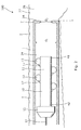
- the self-propelling driving unit it is possible to pull the production casing beyond the point P (shown in Fig. 2 ) at which the production casing, without the self-propelling driving unit, would be stuck, and the rest of the borehole would remain uncased.
- the self-propelling driving unit 10 of Fig. 2 comprises a driving section 11 having propelling means 12.
- the self-propelling driving unit 10 has a first end 41 facing forwards and a second end 42 facing backwards and being nearer the top of the well as the driving unit propels itself forward in the well.
- the propelling means is movable between a retracted position and a projected position, and a pulling section 15 is connected with the driving section and is arranged connecting a wireline 14 with the driving section.
- the pulling section is releasably connected to the first open end of the production casing and the driving section is arranged in front of the production casing, so that the projected propelling means have contact with first the intermediate casing and then the borehole for pulling the production casing forward in the intermediate casing and the borehole.
- the production casing is stuck at the point P, and the self-propelling driving unit 10 has therefore been inserted into the production casing 1 and propels itself forward in the production casing.
- the propelling means are wheels arranged on projectable arms 17, and the propelling means is in a first projected position at which the projectable arms 17 are somewhat projected. In the first projected position, the propelling means is capable of abutting an inner face 24 of the production casing.
- the production casing at the first open end has a projection 16 decreasing a first inner diameter D1 of the production casing to a second inner diameter D2.
- the self-propelling driving unit 10 In order to pull the production casing beyond the point P, the self-propelling driving unit 10 enters an open hole part 26 of the well borehole through the open end 7 of the production casing 1.
- the propelling means 12 first retracts to be able to pass the open end and then the propelling means projects into a second projected position when the wheels abut an inner face 27 of the borehole as shown in Fig. 3 .
- the wheels engage the borehole wall and lift the production casing 1 free of the borehole projection, hence preventing the production casing from moving forward in the borehole, and as the self-propelling driving unit 10 starts propelling, the production casing is pulled as well.
- the pulling section 15 has a larger outer diameter than the second inner diameter D2 of the open end, and the pulling section is thus releasably connected to the first open end of the production casing, and the driving section is arranged in front of the production casing so that the propelling means have contact with the borehole and pulls the production casing forward in the borehole.
- the driving section has an outer diameter D od which is smaller than the second inner diameter D2 when the propelling means is in the retracted position
- the pulling section has an outer diameter D op which is larger than the second inner diameter and smaller than the first inner diameter.
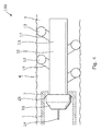
- the projection at the open end of the production casing 1 may have an inclined surface 28 functioning as a ball seat in a subsequent production initiating procedure.
- the pulling section has a corresponding shape so as to match the ball seat and increase the contact between the pulling section 15 and the production casing 1.
- the pulling section 15 has projectable elements 18 which are movable between a projected position and a retracted position. In the retracted position, the pulling section has approximately the same outer diameter as the driving section 11, and in the projected position the pulling section has an outer diameter D po which is larger than second inner diameter, so that the projectable elements 18 abuts the projection of the production casing 1.
- the projectable elements 18 may be dogs, anchors, claws, keys or similar elements capable of projecting radially from a body 29 of the pulling section 15.
- the driving section 11 may also have an outer diameter D od which is substantially equal to the outer diameter D oc of the production casing, when the propelling means are in their retracted position.
- the driving unit comprises a disconnecting means 20 for disconnecting the pulling section from the driving section when the self-propelling driving unit 10 has performed its job and has pulled the production casing beyond the point and further into the borehole.
- the downhole deployment system 100 further comprises a pulling device 19 at the top of the well for pulling the wireline and retracting the pulling device from the production casing, when the disconnecting means 20 of Fig. 6 has been activated and disconnects the pulling section 15 from the driving section 11.
- the disconnecting means may have a timer 36 for activating the disconnecting means when the driving unit has been unpowered for a predetermined time period. By having a timer, the disconnecting means is not activated if the power is temporarily lost but only if the power is intentionally disconnected.
- the downhole deployment system 100 comprises a self-propelling driving unit having two driving sections 11, a first driving section 11a and a second driving section 11b.
- the self-propelling driving unit is connected with an elongated tubing string 45" such as coiled tubing, drill pipe, etc., for conducting fluid to a turbine 44 driven by the fluid for driving a generator 43 driven by the turbine and generating electricity for powering at least one of the driving sections 11, 11a, 11b.
- the first driving section 11a is a fluid-driven driving section
- the fluid in the tubing string is used for driving the pump 39 driving a closed hydraulic system in the first driving section.
- the pump 39 thus drives hydraulic motors 37 in the wheels 12 of the driving section and projects the arms 17.
- the first driving section may also be electrically driven where the electricity from the generator powers a motor driving the pump 39 and thus the wheels and arms, or the motor drives the pump to drive the arms, and electrical motors 37 in the wheels are powered by the electricity from the generator.
- the second driving section 11b is, in Fig. 8 , an electrically driven driving section and is powered by the electricity from the generator to drive a pump driving the arms.
- the motors in the wheels may either be hydraulically driven by the pump or electrically driven by the electricity from the generator.
- the second or electrically driven driving section is arranged in front of the driving unit forming the first end 41, where the pulling section is connected with the second end 42 of the first driving section 11a.
- Both the first and the second driving sections 11, 11a, 11b have a control section (not shown) for controlling the operation of the driving section.
- the turbine drives a hollow shaft for driving the generator and for providing fluid to the pump 39 in order to propel the driving section 11, 11a and the production casing forward in the well when the pulling section engages the production casing.
- the driving unit arrives at the end of the production casing, the projectable elements 18 are projected to engage the production casing, and the driving sections are arranged outside the production casing so the wheels can engage the borehole wall and propel the driving unit and the production casing forward in the well.
- the driving unit may also be installed so the projectable elements 18 engage the end of the production casing when the production casing is lowered into the borehole.
- the driving section has wheels and a motor 37, such as a hydraulic motor or electrical motor, may be arranged in each wheel.
- the driving unit comprises an electrical motor 38 powered through the wireline and driving a pump 39 providing hydraulic power for projecting the propelling means.
- a spring is compressed upon projection of the propelling means, and the inherent force in the compressed spring provides a retraction force when the hydraulic pressure is released for retracting the propelling means.
- the driving unit 10 comprises a swivel connection 25 between the driving section 11 and the pulling section 15 so that the driving section 11 remains unrotated while the production casing is rotated during insertion of the production casing 1.
- the driving unit may comprise a plurality of driving sections 11 as shown in Fig. 7 .
- the driving sections 11 may be arranged at a circumferential angle in relation to each other as shown, so that the propelling means is also capable of centralising the production casing in the transverse direction perpendicular to the longitudinal extension of the borehole.
- the pulling section may comprise a fishing neck for pulling the driving unit if the outer diameter of the driving section is smaller than the inner diameter of the open end of the production casing.
- the driving unit is illustrated having propelling means in the form of wheels but may in another embodiment have caterpillar tracks.
- the downhole deployment system further comprises a pulling device 19 at the top 31 of the well for pulling the wireline and retracting the driving unit from the production casing.
- the production casing comprises an annular barrier 21 to be expanded in an annulus between the production casing and the borehole 4 for providing zone isolation between a first zone and a second zone of the borehole.
- the annular barrier comprises a casing part 32 forming part of the production casing, an expandable sleeve 33 surrounding the casing part and each end of the expandable sleeve being connected with the casing part in two connections 34 defining an annular space (not shown) between the expandable sleeve and the casing part.
- Production zones are isolated by expanding the sleeve of the annular barrier so that the sleeve abuts the wall of the borehole 4.
- the annular barrier may be expanded by pressurising the production casing from within after closing the open end of the production casing.
- the production casing 1 comprises an inflow control section 22 for letting well fluid in and a fracturing port 23 for ejecting fluid out from the production casing for fracturing the formation.
- the inflow control section 22 and the fracturing port 23 are closed from within the production casing 1, e.g. by means of a sliding sleeve (not shown).
- the production casing may be rotated while being inserted into the borehole and a rotation equipment 35 is arranged at the top 31 of the well for rotating the production casing 1.
- the self-propelling driving unit may be used for pulling a production casing forward merely in an intermediate casing so that the well is made as a double cased well.
- a production casing When completing a well downhole by means of the downhole deployment system, a production casing is inserted in an intermediate casing or borehole having a substantially vertical part and a substantially horizontal part.
- the production casing has a first open end furthest away from a top of the well, which end constitutes the front of the production casing as it is inserted into the well.
- a self-propelling driving unit is positioned in connection with the first open end of the production casing so that the pulling section is arranged inside the production casing and the driving section is arranged in front of the production casing.
- the propelling means of the driving section In order to pull the production casing, the propelling means of the driving section is projected so that they are in contact with the intermediate casing or borehole in order to pull the production casing forward in the intermediate casing or borehole.
- the driving unit is inserted subsequent to the production casing being entered into the intermediate casing or borehole.
- Another way of pulling the production casing is to position the self-propelling driving unit in connection with a first open end of the production casing before inserting a production casing with the self-propelling unit in an intermediate casing or borehole.
- the propelling means of the driving section may be projected at any point along the longitudinal extension of the intermediate casing or borehole, so that they are in contact with the intermediate casing or borehole in order to pull the production casing forward in the intermediate casing or borehole.
- the pulling section is released from the open first end of the production casing by either retracting the propelling means and pulling the driving section into the production casing and further up to the top of the well by pulling the wireline, or releasing the pulling section from the driving section and pulling the pulling section up to the top of the well by pulling the wireline.
- acid stimulation via the first open end can be initiated.
- the open end of the production casing is closed and the annular barrier may be expanded by pressurising the casing from within. If the pulling section and the driving unit have been released, the expansion of the annular barriers can be performed by dropping a ball for closing the first open end of the production casing.
- a stroking tool is a tool providing an axial force.
- the stroking tool comprises an electrical motor for driving a pump.
- the pump pumps fluid into a piston housing to move a piston acting therein.
- the piston is arranged on the stroker shaft.
- the pump may pump fluid into the piston housing on one side and simultaneously suck fluid out on the other side of the piston.
- fluid or well fluid any kind of fluid that may be present in oil or gas wells downhole, such as natural gas, oil, oil mud, crude oil, water, etc.
- gas is meant any kind of gas composition present in a well, completion, or open hole
- oil is meant any kind of oil composition, such as crude oil, an oil-containing fluid, etc.
- Gas, oil, and water fluids may thus all comprise other elements or substances than gas, oil, and/or water, respectively.
- a casing any kind of pipe, tubing, tubular, liner, string etc. used downhole in relation to oil or natural gas production.
- a downhole tractor can be used to push the tool all the way into position in the well.
- the downhole tractor may have projectable arms having wheels, wherein the wheels contact the inner surface of the casing for propelling the tractor and the tool forward in the casing.
- a downhole tractor is any kind of driving tool capable of pushing or pulling tools in a well downhole, such as a Well Tractor®.
Landscapes
- Engineering & Computer Science (AREA)
- Life Sciences & Earth Sciences (AREA)
- Geology (AREA)
- Mining & Mineral Resources (AREA)
- Physics & Mathematics (AREA)
- Environmental & Geological Engineering (AREA)
- Fluid Mechanics (AREA)
- General Life Sciences & Earth Sciences (AREA)
- Geochemistry & Mineralogy (AREA)
- Mechanical Engineering (AREA)
- Earth Drilling (AREA)
Abstract
The present invention relates to a downhole deployment system (100) for completing a well (2) downhole, comprising a production casing (1) to be inserted in an intermediate casing (3) or borehole (4) having a substantially vertical part (5) and a substantially horizontal part (6), the production casing having a first open end (7) furthest away from a top (8) of the well, and a self-propelling driving unit (10) being electrically and/or hydraulically driven and comprising a driving section (11) having a first end (41) and a second end (42) and propelling means (12), the propelling means being movable between a retracted position and a projected position in order to propel the driving unit forward in the well with the first end facing forwards, and a pulling section (15) connected to the second end, wherein the pulling section is releasably connected to the first open end of the production casing and the driving section is arranged in front of the production casing so that the propelling means, when being in the projected position, have contact with the intermediate casing or borehole for pulling the production casing forward in the intermediate casing or borehole.
Description
- The present invention relates to a downhole deployment system and a method for completing a well downhole.
- One way of completing a well for oil or gas production is to drill a first part of the borehole, then arrange an intermediate casing in the first part, then drill a second part of the borehole and subsequently run in a production casing by pushing and rotating the production casing. At some point down the borehole, the pushing and rotation force at the top of the well is inadequate to force the production casing further into the borehole as the production casing is stuck and then the insertion process of the production casing will have to be called off. This is due to the fact that there are no known ways of moving on from this this point when inserting the production casing. Hence, casing a well beyond this point is not a conceivable option. Production zones are then isolated and the production initiating procedures are initiated so that production can begin.
- It is an object of the present invention to wholly or partly overcome the above disadvantages and drawbacks of the prior art. More specifically, it is an object to provide an improved downhole deployment system which makes it possible to complete wells having a longer cased borehole than what is possible by means of known solutions.
- The above objects, together with numerous other objects, advantages and features, which will become evident from the below description, are accomplished by a solution in accordance with the present invention by a downhole deployment system for completing a well downhole, comprising
- a production casing to be inserted in an intermediate casing or borehole having a substantially vertical part and a substantially horizontal part, the production casing having a first open end furthest away from a top of the well, and
- a self-propelling driving unit being electrically and/or hydraulically driven and comprising a driving section having a first end and a second end and propelling means, the propelling means being movable between a retracted position and a projected position in order to propel the driving unit forward in the well with the first end facing forwards, and a pulling section connected to the second end,
- The self-propelling driving unit may have a wireline and thus be a wireline self-propelling driving unit.
- Also, the self-propelling driving unit may be connected with an elongated tubing string for conducting fluid in the well, and the driving unit may further comprise a turbine driven by the fluid for driving a generator driven by the turbine and generating electricity for powering the driving section.
- Further, the turbine may drive a hollow shaft for driving the generator and for providing fluid to a pump in order to propel the driving section and the tubing string forward in the well.
- Moreover, the driving unit may further comprise an electrically driven driving section comprising an electrical motor powered by the generator for propelling the driving unit and the production casing forward in the well, the electrically driven driving section being arranged in front of the driving unit forming the first end.
- The production casing at the first open end may have a projection decreasing a first inner diameter of the production casing to a second inner diameter.
- Also, the production casing may have a first inner diameter in a main bore and an inner diameter of an opening at the first open end, the first inner diameter being larger than the inner diameter of the opening.
- Moreover, the driving section may have an outer diameter which is smaller than the second inner diameter when the propelling means is in the retracted position.
- Further, the propelling means may be wheels arranged on projectable arms.
- In addition, the propelling means may be caterpillar tracks.
- The pulling section may have an outer diameter which is larger than the second inner diameter and smaller than the first inner diameter.
- Also, the pulling section may have projectable elements which are movable between a projected position and a retracted position, said pulling section having, in the projected position, an outer diameter which is larger than a second inner diameter, so that the projectable elements abut the opening projection.
- The projectable elements may be dogs, anchors, claws, keys or similar elements capable of projecting radially from a body of the pulling section.
- Furthermore, the downhole deployment system as described above may further comprise a pulling device at the top of the well for pulling a wireline connected with the driving unit and retracting the driving unit from the production casing.
- Additionally, the driving unit may comprise a disconnecting means for disconnecting the pulling section from the driving section, and the system may further comprise a pulling device at the top of the well for pulling the wireline and retracting the pulling device from the production casing.
- Moreover, the driving section may be left downhole.
- Furthermore, the production casing may comprise an annular barrier to be expanded in an annulus between the production casing and the intermediate casing or borehole for providing zone isolation between a first zone and a second zone of the borehole.
- Also, the annular barrier may comprise a casing part, an expandable sleeve surrounding the casing part and having an inner sleeve face facing the casing part and an outer sleeve face facing the borehole, each end of the expandable sleeve being connected with the casing part in two connections, and an annular space between the inner sleeve face of the expandable sleeve and the casing part.
- In addition, the disconnecting means may have a timer for activating the disconnecting means when the driving unit has been unpowered for a predetermined time period.
- The pulling section may comprise a fishing neck for pulling the driving unit.
- Moreover, the propelling means of the driving section may be wheels, and each wheel may comprise a hydraulic motor.
- Further, the propelling means of the driving section may be wheels, and each wheel may comprise an electrical motor.
- Additionally, the driving unit may comprise an electrical motor driving a pump providing hydraulic power for projecting the propelling means.
- The production casing may comprise an inflow control section for letting well fluid in and/or may comprise a fracturing port for ejecting fluid out from the production casing for fracturing the formation.
- Furthermore, a rotation equipment may be arranged at the top of the well for rotating the production casing.
- The driving unit may comprise a swivel connection between the driving section and the pulling section so that the driving section remains unrotated, while the production casing is rotated.
- Also, the driving unit may comprise a plurality of driving sections.
- Moreover, the propelling means may have at least a first projected position and a second projected position, the propelling means being capable, in the first projected position, of abutting the first inner diameter of the production casing, and the propelling means being capable, in the second projected position, of abutting an inner diameter of the intermediate casing or the borehole.
- The present invention also relates to a method for completing a well downhole by means of the downhole deployment system as described above, comprising the steps of:
- inserting a production casing in an intermediate casing or borehole having a substantially vertical part and a substantially horizontal part, the production casing having a first open end furthest away from a top of the well,
- positioning a self-propelling driving unit in connection with the first open end of the production casing, so that the pulling section is arranged inside the production casing and the driving section is arranged in front of the production casing, and
- projecting the propelling means of the driving section so that they are in contact with the intermediate casing or borehole for pulling the production casing forward in the intermediate casing or borehole.
- Said method for completing a well downhole by means of the downhole deployment system as described above may also comprise the steps of:
- positioning a self-propelling driving unit in connection with a first open end of the production casing so that the pulling section is arranged inside the production casing, and the driving section is arranged in front of the production casing,
- inserting a production casing with the self-propelling unit in an intermediate casing or borehole having a substantially vertical part and a substantially horizontal part, the production casing having the first open end furthest away from a top of the well, and
- projecting the propelling means of the driving section so that they are in contact with the intermediate casing or borehole for pulling the production casing forward in the intermediate casing or borehole.
- Also, the method as described above may comprise the step of:
- releasing the driving unit or the pulling section of the driving unit from the open first end of the production casing by either
- retracting the propelling means and pulling the driving section into the production casing and further up to the top of the well by pulling a wireline connected with the driving unit, or
- releasing the pulling section from the driving section and pulling the pulling section up to the top of the well by pulling a wireline connected with the driving unit.
- Further, the method as described above may comprise the step of conducting acid stimulation via the first open end after removal from the production casing of the driving unit or the pulling section of the driving unit.
- Finally, the method as described above may further comprise the step of dropping a ball for closing the first open end of the production casing.
- The invention and its many advantages will be described in more detail below with reference to the accompanying schematic drawings, which for the purpose of illustration show some non-limiting embodiments and in which
-
Fig. 1 shows a downhole deployment system, -
Fig. 2 shows a driving unit in a production casing, -
Fig. 3 shows a driving unit pulling a production casing, -
Fig. 4 shows another driving unit pulling a production casing, -
Fig. 5 shows a driving unit having another pulling section pulling a production casing, -
Fig. 6 shows a driving unit pulling a production casing and having substantially the same diameter as the casing, -
Fig. 7 shows a driving unit having two driving sections propelling themselves forward in a production casing, and -
Fig. 8 shows a driving unit having two driving sections driven by pressurised fluid through coiled tubing. - All the figures are highly schematic and not necessarily to scale, and they show only those parts which are necessary in order to elucidate the invention, other parts being omitted or merely suggested.
-
Fig. 1 shows adownhole deployment system 100 for completing a well 2 in aborehole 4 downhole. Thedownhole deployment system 100 comprises aproduction casing 1 which is inserted through anintermediate casing 3 and then theborehole 4 having a substantiallyvertical part 5 and a substantiallyhorizontal part 6. In the end furthest away from the top 31 of the well, the production casing has a firstopen end 7 from which a self-propellingdriving unit 10 extends for pulling the production casing forward in the borehole while forcing the production casing down from the top of the well. By having the self-propelling driving unit, it is possible to pull the production casing beyond the point P (shown inFig. 2 ) at which the production casing, without the self-propelling driving unit, would be stuck, and the rest of the borehole would remain uncased. - The self-propelling
driving unit 10 ofFig. 2 comprises a drivingsection 11 having propellingmeans 12. The self-propellingdriving unit 10 has afirst end 41 facing forwards and asecond end 42 facing backwards and being nearer the top of the well as the driving unit propels itself forward in the well. The propelling means is movable between a retracted position and a projected position, and a pullingsection 15 is connected with the driving section and is arranged connecting awireline 14 with the driving section. The pulling section is releasably connected to the first open end of the production casing and the driving section is arranged in front of the production casing, so that the projected propelling means have contact with first the intermediate casing and then the borehole for pulling the production casing forward in the intermediate casing and the borehole. - As can be seen in
Figs. 2 and3 , the production casing is stuck at the point P, and the self-propellingdriving unit 10 has therefore been inserted into theproduction casing 1 and propels itself forward in the production casing. The propelling means are wheels arranged onprojectable arms 17, and the propelling means is in a first projected position at which theprojectable arms 17 are somewhat projected. In the first projected position, the propelling means is capable of abutting aninner face 24 of the production casing. The production casing at the first open end has aprojection 16 decreasing a first inner diameter D1 of the production casing to a second inner diameter D2. In order to pull the production casing beyond the point P, the self-propellingdriving unit 10 enters anopen hole part 26 of the well borehole through theopen end 7 of theproduction casing 1. The propelling means 12 first retracts to be able to pass the open end and then the propelling means projects into a second projected position when the wheels abut aninner face 27 of the borehole as shown inFig. 3 . In the second projected position shown inFig. 3 , the wheels engage the borehole wall and lift theproduction casing 1 free of the borehole projection, hence preventing the production casing from moving forward in the borehole, and as the self-propellingdriving unit 10 starts propelling, the production casing is pulled as well. This is due to the fact that the pullingsection 15 has a larger outer diameter than the second inner diameter D2 of the open end, and the pulling section is thus releasably connected to the first open end of the production casing, and the driving section is arranged in front of the production casing so that the propelling means have contact with the borehole and pulls the production casing forward in the borehole. Thus, the driving section has an outer diameter Dod which is smaller than the second inner diameter D2 when the propelling means is in the retracted position, and the pulling section has an outer diameter Dop which is larger than the second inner diameter and smaller than the first inner diameter. - As shown in
Figs. 4 , the projection at the open end of theproduction casing 1 may have aninclined surface 28 functioning as a ball seat in a subsequent production initiating procedure. When the projection is a ball seat, the pulling section has a corresponding shape so as to match the ball seat and increase the contact between the pullingsection 15 and theproduction casing 1. - In
Fig. 5 , the pullingsection 15 hasprojectable elements 18 which are movable between a projected position and a retracted position. In the retracted position, the pulling section has approximately the same outer diameter as the drivingsection 11, and in the projected position the pulling section has an outer diameter Dpo which is larger than second inner diameter, so that theprojectable elements 18 abuts the projection of theproduction casing 1. Theprojectable elements 18 may be dogs, anchors, claws, keys or similar elements capable of projecting radially from abody 29 of the pullingsection 15. - As shown in
Fig. 6 , the drivingsection 11 may also have an outer diameter Dod which is substantially equal to the outer diameter Doc of the production casing, when the propelling means are in their retracted position. Then the driving unit comprises a disconnecting means 20 for disconnecting the pulling section from the driving section when the self-propellingdriving unit 10 has performed its job and has pulled the production casing beyond the point and further into the borehole. As shown inFig. 1 , thedownhole deployment system 100 further comprises a pullingdevice 19 at the top of the well for pulling the wireline and retracting the pulling device from the production casing, when the disconnecting means 20 ofFig. 6 has been activated and disconnects the pullingsection 15 from the drivingsection 11. In this way, the driving section is left downhole and the wireline and the pullingsection 15 are drawn up from the production casing. The disconnecting means may have atimer 36 for activating the disconnecting means when the driving unit has been unpowered for a predetermined time period. By having a timer, the disconnecting means is not activated if the power is temporarily lost but only if the power is intentionally disconnected. - In
Fig. 8 , thedownhole deployment system 100 comprises a self-propelling driving unit having two drivingsections 11, afirst driving section 11a and asecond driving section 11b. The self-propelling driving unit is connected with anelongated tubing string 45" such as coiled tubing, drill pipe, etc., for conducting fluid to aturbine 44 driven by the fluid for driving agenerator 43 driven by the turbine and generating electricity for powering at least one of the drivingsections - In the event that the
first driving section 11a is a fluid-driven driving section, the fluid in the tubing string is used for driving thepump 39 driving a closed hydraulic system in the first driving section. Thepump 39 thus driveshydraulic motors 37 in thewheels 12 of the driving section and projects thearms 17. The first driving section may also be electrically driven where the electricity from the generator powers a motor driving thepump 39 and thus the wheels and arms, or the motor drives the pump to drive the arms, andelectrical motors 37 in the wheels are powered by the electricity from the generator. - The
second driving section 11b is, inFig. 8 , an electrically driven driving section and is powered by the electricity from the generator to drive a pump driving the arms. The motors in the wheels may either be hydraulically driven by the pump or electrically driven by the electricity from the generator. The second or electrically driven driving section is arranged in front of the driving unit forming thefirst end 41, where the pulling section is connected with thesecond end 42 of thefirst driving section 11a. - Both the first and the
second driving sections pump 39 in order to propel the drivingsection projectable elements 18 are projected to engage the production casing, and the driving sections are arranged outside the production casing so the wheels can engage the borehole wall and propel the driving unit and the production casing forward in the well. The driving unit may also be installed so theprojectable elements 18 engage the end of the production casing when the production casing is lowered into the borehole. - As shown, the driving section has wheels and a
motor 37, such as a hydraulic motor or electrical motor, may be arranged in each wheel. The driving unit comprises anelectrical motor 38 powered through the wireline and driving apump 39 providing hydraulic power for projecting the propelling means. A spring is compressed upon projection of the propelling means, and the inherent force in the compressed spring provides a retraction force when the hydraulic pressure is released for retracting the propelling means. The drivingunit 10 comprises aswivel connection 25 between the drivingsection 11 and the pullingsection 15 so that the drivingsection 11 remains unrotated while the production casing is rotated during insertion of theproduction casing 1. - Dependent on the distance along which the production casing needs to be pulled, the driving unit may comprise a plurality of driving
sections 11 as shown inFig. 7 . Furthermore, the drivingsections 11 may be arranged at a circumferential angle in relation to each other as shown, so that the propelling means is also capable of centralising the production casing in the transverse direction perpendicular to the longitudinal extension of the borehole. - Even though not shown, the pulling section may comprise a fishing neck for pulling the driving unit if the outer diameter of the driving section is smaller than the inner diameter of the open end of the production casing. Furthermore, the driving unit is illustrated having propelling means in the form of wheels but may in another embodiment have caterpillar tracks.
- In
Fig. 1 , the downhole deployment system further comprises a pullingdevice 19 at the top 31 of the well for pulling the wireline and retracting the driving unit from the production casing. The production casing comprises anannular barrier 21 to be expanded in an annulus between the production casing and theborehole 4 for providing zone isolation between a first zone and a second zone of the borehole. The annular barrier comprises acasing part 32 forming part of the production casing, anexpandable sleeve 33 surrounding the casing part and each end of the expandable sleeve being connected with the casing part in twoconnections 34 defining an annular space (not shown) between the expandable sleeve and the casing part. Production zones are isolated by expanding the sleeve of the annular barrier so that the sleeve abuts the wall of theborehole 4. The annular barrier may be expanded by pressurising the production casing from within after closing the open end of the production casing. - As shown in
Fig. 1 , theproduction casing 1 comprises aninflow control section 22 for letting well fluid in and a fracturingport 23 for ejecting fluid out from the production casing for fracturing the formation. When the annular barriers are expanded by means of pressurised fluid, theinflow control section 22 and the fracturingport 23 are closed from within theproduction casing 1, e.g. by means of a sliding sleeve (not shown). - As earlier mentioned, the production casing may be rotated while being inserted into the borehole and a
rotation equipment 35 is arranged at the top 31 of the well for rotating theproduction casing 1. Even though not explicitly shown, the self-propelling driving unit may be used for pulling a production casing forward merely in an intermediate casing so that the well is made as a double cased well. - When completing a well downhole by means of the downhole deployment system, a production casing is inserted in an intermediate casing or borehole having a substantially vertical part and a substantially horizontal part. The production casing has a first open end furthest away from a top of the well, which end constitutes the front of the production casing as it is inserted into the well. A self-propelling driving unit is positioned in connection with the first open end of the production casing so that the pulling section is arranged inside the production casing and the driving section is arranged in front of the production casing. In order to pull the production casing, the propelling means of the driving section is projected so that they are in contact with the intermediate casing or borehole in order to pull the production casing forward in the intermediate casing or borehole. In this method, the driving unit is inserted subsequent to the production casing being entered into the intermediate casing or borehole.
- Another way of pulling the production casing is to position the self-propelling driving unit in connection with a first open end of the production casing before inserting a production casing with the self-propelling unit in an intermediate casing or borehole. The propelling means of the driving section may be projected at any point along the longitudinal extension of the intermediate casing or borehole, so that they are in contact with the intermediate casing or borehole in order to pull the production casing forward in the intermediate casing or borehole.
- Subsequent to a completed pulling operation, the pulling section is released from the open first end of the production casing by either retracting the propelling means and pulling the driving section into the production casing and further up to the top of the well by pulling the wireline, or releasing the pulling section from the driving section and pulling the pulling section up to the top of the well by pulling the wireline.
- After the release operation, acid stimulation via the first open end can be initiated.
- Before release of the pulling section, the open end of the production casing is closed and the annular barrier may be expanded by pressurising the casing from within. If the pulling section and the driving unit have been released, the expansion of the annular barriers can be performed by dropping a ball for closing the first open end of the production casing.
- A stroking tool is a tool providing an axial force. The stroking tool comprises an electrical motor for driving a pump. The pump pumps fluid into a piston housing to move a piston acting therein. The piston is arranged on the stroker shaft. The pump may pump fluid into the piston housing on one side and simultaneously suck fluid out on the other side of the piston.
- By fluid or well fluid is meant any kind of fluid that may be present in oil or gas wells downhole, such as natural gas, oil, oil mud, crude oil, water, etc. By gas is meant any kind of gas composition present in a well, completion, or open hole, and by oil is meant any kind of oil composition, such as crude oil, an oil-containing fluid, etc. Gas, oil, and water fluids may thus all comprise other elements or substances than gas, oil, and/or water, respectively.
- By a casing is meant any kind of pipe, tubing, tubular, liner, string etc. used downhole in relation to oil or natural gas production.
- In the event that the tool is not submergible all the way into the casing, a downhole tractor can be used to push the tool all the way into position in the well. The downhole tractor may have projectable arms having wheels, wherein the wheels contact the inner surface of the casing for propelling the tractor and the tool forward in the casing. A downhole tractor is any kind of driving tool capable of pushing or pulling tools in a well downhole, such as a Well Tractor®.
- Although the invention has been described in the above in connection with preferred embodiments of the invention, it will be evident for a person skilled in the art that several modifications are conceivable without departing from the invention as defined by the following claims.
Claims (15)
- A downhole deployment system (100) for completing a well (2) downhole, comprising- a production casing (1) to be inserted in an intermediate casing (3) or borehole (4) having a substantially vertical part (5) and a substantially horizontal part (6), the production casing having a first open end (7) furthest away from a top (8) of the well, and- a self-propelling driving unit (10) being electrically and/or hydraulically driven and comprising a driving section (11) having a first end (41) and a second end (42) and propelling means (12), the propelling means being movable between a retracted position and a projected position in order to propel the driving unit forward in the well with the first end facing forwards, and a pulling section (15) connected to the second end,wherein the pulling section is releasably connected to the first open end of the production casing and the driving section is arranged in front of the production casing so that the propelling means, when being in the projected position, have contact with the intermediate casing or borehole for pulling the production casing forward in the intermediate casing or borehole.
- A downhole deployment system according to claim 1, wherein the production casing at the first open end has a projection (16) decreasing a first inner diameter (D1) of the production casing to a second inner diameter (D2).
- A downhole deployment system according to claim 2, wherein the driving section has an outer diameter (Ddo) which is smaller than the second inner diameter (D2) when the propelling means is in the retracted position.
- A downhole deployment system according to any of the preceding claims, wherein the propelling means are wheels arranged on projectable arms (17).
- A downhole deployment system according to claim 2, wherein the pulling section has an outer diameter (Dpo) which is larger than the second inner diameter and smaller than the first inner diameter.
- A downhole deployment system according to claim 2, wherein the pulling section has projectable elements (18) which are movable between a projected position and a retracted position, said pulling section having, in the projected position, an outer diameter (Dpo) which is larger than a second inner diameter, so that the projectable elements abut the opening projection.
- A downhole deployment system according to any of the preceding claims, further comprising a pulling device (19) at the top of the well for pulling a wireline connected with the driving unit and retracting the driving unit from the production casing.
- A downhole deployment system according to any of the claims 1-7, wherein the driving unit comprises a disconnecting means (20) for disconnecting the pulling section from the driving section.
- A downhole deployment system according to any of the preceding claims, wherein the production casing comprises an annular barrier (21) to be expanded in an annulus (2) between the production casing and the intermediate casing (3) or borehole (4) for providing zone isolation between a first zone (101) and a second zone (102) of the borehole.
- A downhole deployment system according to any of the preceding claims, wherein the production casing comprises an inflow control section (22) for letting well fluid in and/or comprises a fracturing port (23) for ejecting fluid out from the production casing for fracturing the formation.
- A downhole deployment system according to claim 10, wherein the driving unit comprises a swivel connection (25) between the driving section and the pulling section so that the driving section remains unrotated, while the production casing is rotated.
- A downhole deployment system according to any of the preceding claims, wherein the propelling means has at least a first projected position and a second projected position, the propelling means being capable, in the first projected position, of abutting the first inner diameter of the production casing, and the propelling means being capable, in the second projected position, of abutting an inner diameter of the intermediate casing or the borehole.
- A method for completing a well downhole by means of the downhole deployment system according to any of the preceding claims, comprising the steps of:- inserting a production casing in an intermediate casing or borehole having a substantially vertical part and a substantially horizontal part, the production casing having a first open end furthest away from a top of the well,- positioning a self-propelling driving unit in connection with the first open end of the production casing, so that the pulling section is arranged inside the production casing and the driving section is arranged in front of the production casing, and- projecting the propelling means of the driving section so that they are in contact with the intermediate casing or borehole for pulling the production casing forward in the intermediate casing or borehole.
- A method for completing a well downhole by means of the downhole deployment system according to any of the claims 1-12, comprising the steps of:- positioning a self-propelling driving unit in connection with a first open end of the production casing so that the pulling section is arranged inside the production casing, and the driving section is arranged in front of the production casing,- inserting a production casing with the self-propelling unit in an intermediate casing or borehole having a substantially vertical part and a substantially horizontal part, the production casing having the first open end furthest away from a top of the well, and- projecting the propelling means of the driving section so that they are in contact with the intermediate casing or borehole for pulling the production casing forward in the intermediate casing or borehole.
- A method according to claim 13 or 14, comprising the step of:- releasing the driving unit or the pulling section of the driving unit from the open first end of the production casing by either- retracting the propelling means and pulling the driving section into the production casing and further up to the top of the well by pulling a wireline connected with the driving unit, or- releasing the pulling section from the driving section and pulling the pulling section up to the top of the well by pulling a wireline connected with the driving unit.
Priority Applications (2)
| Application Number | Priority Date | Filing Date | Title |
|---|---|---|---|
| EP13197533.6A EP2884044A1 (en) | 2013-12-16 | 2013-12-16 | Retrievable liner or casing deployment system |
| PCT/EP2014/077900 WO2015091441A1 (en) | 2013-12-16 | 2014-12-16 | Retrievable liner or casing deployment system |
Applications Claiming Priority (1)
| Application Number | Priority Date | Filing Date | Title |
|---|---|---|---|
| EP13197533.6A EP2884044A1 (en) | 2013-12-16 | 2013-12-16 | Retrievable liner or casing deployment system |
Publications (1)
| Publication Number | Publication Date |
|---|---|
| EP2884044A1 true EP2884044A1 (en) | 2015-06-17 |
Family
ID=49882824
Family Applications (1)
| Application Number | Title | Priority Date | Filing Date |
|---|---|---|---|
| EP13197533.6A Withdrawn EP2884044A1 (en) | 2013-12-16 | 2013-12-16 | Retrievable liner or casing deployment system |
Country Status (2)
| Country | Link |
|---|---|
| EP (1) | EP2884044A1 (en) |
| WO (1) | WO2015091441A1 (en) |
Cited By (4)
| Publication number | Priority date | Publication date | Assignee | Title |
|---|---|---|---|---|
| CN105927169A (en) * | 2016-05-12 | 2016-09-07 | 西南石油大学 | Drilling pressure and torque amplifier for coiled tubing |
| NO20150865A1 (en) * | 2015-07-03 | 2017-01-04 | Qinterra Tech As | Method of removing equipment from a section of a wellbore and related apparatus |
| WO2019121620A1 (en) * | 2017-12-19 | 2019-06-27 | Welltec A/S | Offshore coiled tubing system |
| EP3514320A1 (en) * | 2018-01-19 | 2019-07-24 | Welltec A/S | Offshore coiled tubing system |
Families Citing this family (3)
| Publication number | Priority date | Publication date | Assignee | Title |
|---|---|---|---|---|
| WO2018094368A1 (en) * | 2016-11-21 | 2018-05-24 | Schroit Sam | System for the operational and performance efficiency improvement of wireline tractors |
| CN115853419B (en) * | 2021-09-27 | 2025-11-21 | 中国石油化工股份有限公司 | Peristaltic propulsion device for natural gas hydrate coiled tubing drilling |
| CN117588177A (en) * | 2023-12-05 | 2024-02-23 | 中海石油(中国)有限公司 | A hydraulic hand-off tool |
Citations (3)
| Publication number | Priority date | Publication date | Assignee | Title |
|---|---|---|---|---|
| US6032733A (en) * | 1997-08-22 | 2000-03-07 | Halliburton Energy Services, Inc. | Cable head |
| US20040060709A1 (en) * | 2002-10-01 | 2004-04-01 | Halliburton Energy Services, Inc. | Apparatus and methods for installing casing in a borehole |
| US20130068479A1 (en) * | 2011-09-19 | 2013-03-21 | Saudi Arabian Oil Company | Well Tractor With Active Traction Control |
Family Cites Families (2)
| Publication number | Priority date | Publication date | Assignee | Title |
|---|---|---|---|---|
| US7273108B2 (en) * | 2004-04-01 | 2007-09-25 | Bj Services Company | Apparatus to allow a coiled tubing tractor to traverse a horizontal wellbore |
| US20080217024A1 (en) * | 2006-08-24 | 2008-09-11 | Western Well Tool, Inc. | Downhole tool with closed loop power systems |
-
2013
- 2013-12-16 EP EP13197533.6A patent/EP2884044A1/en not_active Withdrawn
-
2014
- 2014-12-16 WO PCT/EP2014/077900 patent/WO2015091441A1/en not_active Ceased
Patent Citations (3)
| Publication number | Priority date | Publication date | Assignee | Title |
|---|---|---|---|---|
| US6032733A (en) * | 1997-08-22 | 2000-03-07 | Halliburton Energy Services, Inc. | Cable head |
| US20040060709A1 (en) * | 2002-10-01 | 2004-04-01 | Halliburton Energy Services, Inc. | Apparatus and methods for installing casing in a borehole |
| US20130068479A1 (en) * | 2011-09-19 | 2013-03-21 | Saudi Arabian Oil Company | Well Tractor With Active Traction Control |
Cited By (9)
| Publication number | Priority date | Publication date | Assignee | Title |
|---|---|---|---|---|
| NO20150865A1 (en) * | 2015-07-03 | 2017-01-04 | Qinterra Tech As | Method of removing equipment from a section of a wellbore and related apparatus |
| WO2017007331A1 (en) * | 2015-07-03 | 2017-01-12 | Qinterra Technologies As | Method of removing equipment from a section of a wellbore and related apparatus |
| GB2555548A (en) * | 2015-07-03 | 2018-05-02 | Qinterra Tech As | Method of removing equipment from a section of a wellbore and related apparatus |
| NO342686B1 (en) * | 2015-07-03 | 2018-07-02 | Qinterra Tech As | A tool string for removing equipment from a wellbore, and related method |
| US10605028B2 (en) | 2015-07-03 | 2020-03-31 | Qinterra Technologies As | Method of removing equipment from a section of a wellbore and related apparatus |
| GB2555548B (en) * | 2015-07-03 | 2021-02-10 | Qinterra Tech As | Method of removing equipment from a section of a wellbore and related apparatus |
| CN105927169A (en) * | 2016-05-12 | 2016-09-07 | 西南石油大学 | Drilling pressure and torque amplifier for coiled tubing |
| WO2019121620A1 (en) * | 2017-12-19 | 2019-06-27 | Welltec A/S | Offshore coiled tubing system |
| EP3514320A1 (en) * | 2018-01-19 | 2019-07-24 | Welltec A/S | Offshore coiled tubing system |
Also Published As
| Publication number | Publication date |
|---|---|
| WO2015091441A1 (en) | 2015-06-25 |
Similar Documents
| Publication | Publication Date | Title |
|---|---|---|
| AU2019212858B2 (en) | Downhole wireline intervention tool | |
| US9556693B2 (en) | Disconnecting tool | |
| WO2015091441A1 (en) | Retrievable liner or casing deployment system | |
| EP3414420B1 (en) | Downhole device and downhole system | |
| EP2728108A1 (en) | A downhole stimulation system and a drop device | |
| EP3784873B1 (en) | Workover tool string | |
| CN104641070A (en) | Drop device | |
| US20200217170A1 (en) | Downhole method | |
| EP3908733B1 (en) | Downhole method | |
| US10641054B2 (en) | Retrieval system | |
| EP2960427A1 (en) | Downhole stimulation system | |
| EP3680447A1 (en) | A downhole method | |
| EP3800322A1 (en) | Downhole method |
Legal Events
| Date | Code | Title | Description |
|---|---|---|---|
| PUAI | Public reference made under article 153(3) epc to a published international application that has entered the european phase |
Free format text: ORIGINAL CODE: 0009012 |
|
| 17P | Request for examination filed |
Effective date: 20131216 |
|
| AK | Designated contracting states |
Kind code of ref document: A1 Designated state(s): AL AT BE BG CH CY CZ DE DK EE ES FI FR GB GR HR HU IE IS IT LI LT LU LV MC MK MT NL NO PL PT RO RS SE SI SK SM TR |
|
| AX | Request for extension of the european patent |
Extension state: BA ME |
|
| STAA | Information on the status of an ep patent application or granted ep patent |
Free format text: STATUS: THE APPLICATION IS DEEMED TO BE WITHDRAWN |
|
| 18D | Application deemed to be withdrawn |
Effective date: 20151218 |