EP2884039A1 - Slidable insect screen of a building aperture - Google Patents
Slidable insect screen of a building aperture Download PDFInfo
- Publication number
- EP2884039A1 EP2884039A1 EP14020109.6A EP14020109A EP2884039A1 EP 2884039 A1 EP2884039 A1 EP 2884039A1 EP 14020109 A EP14020109 A EP 14020109A EP 2884039 A1 EP2884039 A1 EP 2884039A1
- Authority
- EP
- European Patent Office
- Prior art keywords
- screen
- wire mesh
- side rails
- height direction
- insect
- Prior art date
- Legal status (The legal status is an assumption and is not a legal conclusion. Google has not performed a legal analysis and makes no representation as to the accuracy of the status listed.)
- Withdrawn
Links
- 241000238631 Hexapoda Species 0.000 title claims abstract description 79
- 238000012216 screening Methods 0.000 claims description 8
- 238000009434 installation Methods 0.000 description 12
- 239000000463 material Substances 0.000 description 6
- 230000008878 coupling Effects 0.000 description 4
- 238000010168 coupling process Methods 0.000 description 4
- 238000005859 coupling reaction Methods 0.000 description 4
- 239000004800 polyvinyl chloride Substances 0.000 description 3
- 229920000915 polyvinyl chloride Polymers 0.000 description 3
- 238000005728 strengthening Methods 0.000 description 3
- 230000000994 depressogenic effect Effects 0.000 description 2
- 239000011152 fibreglass Substances 0.000 description 2
- 230000001771 impaired effect Effects 0.000 description 2
- -1 polypropylene Polymers 0.000 description 2
- 239000004677 Nylon Substances 0.000 description 1
- 239000004698 Polyethylene Substances 0.000 description 1
- 239000004743 Polypropylene Substances 0.000 description 1
- 238000004026 adhesive bonding Methods 0.000 description 1
- 239000002184 metal Substances 0.000 description 1
- 229920001778 nylon Polymers 0.000 description 1
- 239000004033 plastic Substances 0.000 description 1
- 229920003023 plastic Polymers 0.000 description 1
- 229920000573 polyethylene Polymers 0.000 description 1
- 229920001155 polypropylene Polymers 0.000 description 1
- 229920001343 polytetrafluoroethylene Polymers 0.000 description 1
- 239000004810 polytetrafluoroethylene Substances 0.000 description 1
- 230000001932 seasonal effect Effects 0.000 description 1
- 229920002994 synthetic fiber Polymers 0.000 description 1
- 238000003466 welding Methods 0.000 description 1
Images



Classifications
-
- E—FIXED CONSTRUCTIONS
- E06—DOORS, WINDOWS, SHUTTERS, OR ROLLER BLINDS IN GENERAL; LADDERS
- E06B—FIXED OR MOVABLE CLOSURES FOR OPENINGS IN BUILDINGS, VEHICLES, FENCES OR LIKE ENCLOSURES IN GENERAL, e.g. DOORS, WINDOWS, BLINDS, GATES
- E06B9/00—Screening or protective devices for wall or similar openings, with or without operating or securing mechanisms; Closures of similar construction
- E06B9/52—Devices affording protection against insects, e.g. fly screens; Mesh windows for other purposes
Definitions
- the present invention relates to an insect screen of a building aperture, having a supply condition and a condition of use, comprising first and second side rails extending substantially in parallel to each other in a first longitudinal direction defining, in the condition of use, a height direction, said first longitudinal direction being substantially perpendicular to a second longitudinal direction defining a width direction, a screen of wire mesh with opposing marginal areas in said width direction adapted for being in releasable engagement with said first and second side rails in the condition of use.
- casement windows are provided with an insect screen at the interior side of the window, the user's access to the operating handle of the window may be impaired.
- the insect screen is an insect net used in the summertime where it is also desirable to open and close the window relatively often depending on the time of the day.
- an insect net mounted in relation to a window must not leave any opening allowing the user to reach the operating handle of the window, as this would impair the function of the insect net, it is desirable to provide an insect net for a building aperture that is easily removed and repositioned in order to allow the user to operate the window as desired and still have the aperture screened between operation of the window.
- DE 93 14 022 U1 discloses an insect screen having a screen of insect net adapted for mounting in relation to an aperture of a roof light.
- An upper rail of the insect screen is fastened with screws to an upper part of the aperture and sides of the apertures are provided with side rails of a magnetic band.
- Marginal areas of the screen of insect net are provided with a corresponding magnetic band in order to provide a releasable engagement between the side rails and screen of insect net.
- the screen of insect net may be positioned in either an open or closed position.
- US 4,825,921 discloses a screen assembly having a web of material and a pair of spaced opposed elongate strengthening elements as well as two opposed guide rails and a take-up roll.
- the strengthening elements are guided on the guide rails such as to enable retraction and withdrawal of the web of material to and from the take-up roll.
- the strengthening elements are adapted to form a tight roll when rolled up on the take-up roll and are thus resilient in substantially the same way as a coil spring.
- each of the side rails comprises a track providing a sliding engagement with the opposing marginal areas in the width direction of screen of wire mesh
- the screen of wire mesh is slidably movable in the height direction with respect to the side rails so that a portion of the screen of wire mesh may be released from the engagement with the side rails, the opposing marginal areas in the width direction being reinforced by respective bands extending in the height direction and engaging with respective tracks of the side rails, and particularly in that the screen of wire mesh is flexible in at least the height direction so that a freely hanging portion of the screen of wire mesh released from the engagement with the side rails may bend away from the plane defined by the height direction and the width direction, the screen of wire mesh is resilient in at least the width direction such as to enable a freely hanging portion of the screen of wire mesh released from the engagement with the side rails to remain substantially straight in at least the width direction, and the respective bands are flexible in their longitudinal direction and adapted for being rigid when the bands are located in the
- the insect screen according to the invention may advantageously be mounted in relation to many different types of windows mounted in a building aperture. Due to the possible flexible positioning of the screen of mesh wire, the insect screen may be used in combination with windows of the type operated by a through-going operating handle in relation to the upper sash part of a roof window, but also with other kinds of casement windows of both the side-hung and top-hung type.
- the bands in respective opposing sides of the screens of wire mesh may engage with tracks or grooves of the side rails.
- any tolerances from an imprecise installation of the side rails may be absorbed without impairing the screening of the aperture and the operation of the screen of wire mesh.
- the bands which preferably are of a flexible material allowing the screen of wire mesh to be rolled up during transportation, protects the marginal areas both during transportation and during operation against wear and tear.
- the screen of wire mesh is flexible in at least the height direction, yet resilient in at least the width direction, and as the respective bands are flexible in their longitudinal direction and adapted for being rigid when located in the respective tracks the screen of wire mesh may, when a portion of the wire mesh is hanging freely, be kept in a position not disturbing a user operating the window and simultaneously it becomes very easy for the user to move the freely hanging part of the wires mesh back into the tracks without any risk of jamming or tearing the screen of wire mesh.
- a first marginal area in the height direction of the screen of wire mesh is provided with a first operating element being movable in the height direction.
- the operating element also entails a proper stretching of the screen of wire mesh between the side rail and that forces applied to the screen of wire mesh is transferred to the reinforced marginal areas engaging with the tracks of the side rails.
- One or more operating elements guided between the side rails e.g. by a sliding engagement with tracks of each of the side rails, provides for an improved parallel motion of the marginal areas of the screen of wire mesh with respect to the side rails. As the screen of wire mesh is manually operated by pushing or pulling it in the height direction, the provision of operating elements may further facilitate such movement.
- a second marginal area in the height direction of the screen of wire mesh is provided with a second operating element being movable in the height direction.
- This further operating element may be of the same type as the first operating element or for instance be of a less prominent size such as a beading serving to protect the edge of the screen of wire mesh and to stretch the screen of wire mesh between the side rails.
- both operating elements may be provided as beadings for protecting and stretching the screen of wire mesh between the side rails.
- the operating elements at both marginal areas in the height direction of the screen of wire mesh facilitates installation and operation of the insect screen as it's operation is more independent on how the insect screen is mounted.
- the engagement between the screen of wire mesh and the side rails is releasable in two directions of the height direction.
- This feature is especially useful when using the insect screen according to the invention for screening apertures of roof windows mounted in an inclined roof, because the distance between the apertures and the floor from which the user is to operate the window and the insect screen varies from building to building.
- it is desirable to move the screen of wire mesh upwards in the height direction to access the operating handle of the window whereas is other installations it is more desirable to move the screen of wire mesh towards the floor in order to provide access to the operating handle.
- the insect screen according to the invention and it's flexible use may be obtained in connection with many different types of apertures and even in very different types of building structures.
- the screen of wire mesh When the screen of wire mesh is moved downwards, the screen of wire mesh may unintentionally be released from the tracks of the side rails.
- the tracks of the side rails are provided with stop members engaging with the operating members when moved downwards with respect to the height direction.
- the stop members may also be adapted to engage with the operating members when moved upwards in the height direction.
- the slidable insect screen further comprises stop members provided at an end of the side rails and at least one element adapted for frictionally engaging the stop members and provided at an end of the screen of wire mesh such that in the use condition of the screening device the stop members and the at least one element adapted for frictionally engaging the stop members are located at the same end of the insect screen.
- the at least one element adapted for frictionally engaging the stop members may be provided on the screen of wire mesh and/or on one of the bands.
- the screen of wire mesh is prevented from being removed completely from the side rails during use, thus further simplifying the operation of the insect screen and preventing damage to the screen of wire mesh which might otherwise occur when reinserting it into the side rails.
- a guide member extends between the side rails so as to guide the screen of wire mesh when released from the sliding engagement with the side rails.
- the two above-mentioned embodiments provide a more smooth operation of the screen of wire mesh when it is moved with respect to the side rails as it allows the screen of wire mesh to be guided away from the aperture so that the part of screen of wire mesh released from the side rails does not prevent the user to access the operating handle of the window by partly screening the aperture without engaging the tracks of the side rails.
- the presence of a guide member prevents that the marginal areas are to be guided on any edges on the tracks of the side rails when being released from the sliding engagement.
- the friction between the full width of the screen of wire mesh and the guide member ensures that the screen of wire mesh is kept in any desired position.
- the side rails are releasably mounted on respective mounting rails adapted to receive the side rails. This allows for a dismounting at the end of the season and re-mounting at the beginning of the season in an easy manner without use of any tools.
- the guide member is releasably mounted on the side rails so that only the mounting rails are left outside the season when there is no need of an insect screen for keeping insects outside.
- the insect screen further comprises a stop mechanism, the stop mechanism comprising a first part provided at an end of the side rails and a second part provided at an end of the screen of wire mesh such that in the use condition of the screening device the first part and the second part of the stop mechanism are located at mutually opposite ends of the insect screen.
- the second part of the stop mechanism may be provided on any one or more of the screen of wire mesh, one or both of the bands and the operating member.
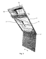
- Fig. 1 an insect screen 1 according to the invention mounted on a sash 51 of a roof window.
- the insect screen 1 comprises a lightweight screen of wire mesh 4 and side rails 2, 3 securing the screen of wire mesh 4 to the sash 51.
- the screen of wire mesh 4 is an insect net adapted to cover an aperture of a window in order to prevent insects, leaves, debris, birds and the like from entering the building while a flow of fresh air into the building is permitted.
- the screen of wire mesh 4 may be a wire net of metal, fibreglass and the like synthetic fibres in a mesh or a plastic mesh made from polypropylene, polyethylene, nylon, PVC or PTFE or the like materials.
- the screen of wire mesh 4 is a PVC coated insect net of fibreglass.
- the screen of wire mesh 4 is preferably made so flexible that it may be rolled up for easier handling during storage outside the season or in a supply condition of the insect screen 1.
- the side rails 2, 3 are mounted substantially in parallel to each other in a first longitudinal direction and defines, in a condition of use as illustrated in Fig. 1 and 2 , a height direction h, which is substantially perpendicular to a second longitudinal direction defining a width direction w.
- Each of the side rails 2, 3 are provided with a through-going track 7 extending in the height direction h and being adapted to receive respective margin areas 5, 6 of the screen of wire mesh 4 in order to provide a sliding engagement between side rails 2, 3 mounted on the aperture and the screen of wire mesh 4.
- the side rails 2, 3 serves as side rails mounting the screen of wire mesh 4 to the aperture to be screened.
- the friction between the marginal areas 5, 6 of the screen of wire mesh 4 and the respective tracks 7 of the side rails 2, 3 allows the screen of wire mesh 4 to be positioned in any desired position along the height direction h. Also, the screen of wire mesh 4 and the side rails 2, 3 have substantially the same length, size or extension measured in the height direction h.
- the sliding engagement between the side rail 2, 3 and the screen of wire mesh 4 allows the screen of wire mesh 4 to be slidable movable in the height direction h with respect to the side rails 2, 3 so that a portion of the screen of wire mesh 4 may be released from the engagement with the respective tracks 7 of the side rail 2, 3.
- Fig. 1 where the screen of wire mesh 4 has been moved downwards with respect to the window installation by pulling an operating member 10.
- a portion of the screen of wire mesh 4 is freely hanging from the lower portion of the side rails 2, 3 and an upper portion of the aperture or the sash 51 is not covered by screen of wire mesh 4 so that a operating handle of the window (not shown) located in the upper portion of the sash may be accessed by a user of the window.
- the screen of wire mesh 4 is flexible in at least the height direction h so that a freely hanging portion of the screen of wire mesh 4 released from the engagement with the side rails 2, 3 may bend away from the plane defined by the height direction h and the width direction w.
- the released portion bends away from said plane in a smooth curve so as to reduce friction between the side rail 2, 3 an the screen of wire mesh.
- the screen of wire mesh 4 is sufficiently resilient in the width direction w to enable a freely hanging portion of the screen of wire mesh 4 released from the engagement with the side rails 2, 3 to remain substantially straight or unbend in the width direction w.
- the screen of wire mesh 4 may be pulled upwards by pulling a further operating handle 9.
- the screen of wire mesh 4 may be moved upwards in the height direction has shown in principle in Fig. 4 , i.e. in the embodiment of Fig. 1 the tracks 7 of the side rails 2, 3 allows the screen of wire mesh 4 to be released from the sliding engagement in both directions both upwardly and downwardly in the height direction.
- the insect screen is equally suitable for an aperture with a window 50 having the operating handle is positioned on a lower portion or on a side portion of the sash 51 and frame.
- the operating handles 9, 10 extend between the side rails 2, 3 in the width direction w and are preferably guided in the tracks 7 of the side rails. Moreover, the provision of operating handles 9, 10 protect the marginal areas in the height direction of the screen of wire mesh 4 and ensure that the screen of wire mesh 4 is stretched between the side rails 2, 3.
- FIG. 2 an insect screen 1 according to the invention has been mounted in relation to an aperture of a roof window 50 in an inclined roof.
- the roof window 50 is shown in an open position and the screen of wire mesh 4 has been moved downwards with respect to the roof window 50.
- the sash 51 may moved to a position where it is slightly open but which also allows the screen of wire mesh 4 to be moved upwards in order to screen the entire aperture. This allows a fresh air-flow while the desired screening of the aperture is maintained.
- the insect screen 1 is provided with a guide member 12 extending between the side rails 2, 3.
- the guide member 12 has a tubular or rounded shape and serves to guide the screen of wire mesh 4 away from the side rails 2, 3. This provides for a smoother operation and protects the screen of wire mesh 4 from being guided directly on edges of the side rails 2, 3 when a portion of the screen of wire mesh 4 is released from the tracks 7. In the particular installation of Fig. 2 the guide member 12 is positioned at a lower end with respect to the height direction h between the side rails 2, 3.
- the guide member 12 may be positioned at the upper end of the side rails 2, 3 in order to guide and protect the screen of wire mesh 4 when moved upwards to be at least partly released from the engagement with the tracks of the side rails 2, 3.
- a guide member 12 may be provided at both ends of the side rail 2, 3 in cases operation in both the upward and the downward direction is desirable for the same installation.
- Fig. 3 is a front view of an insect screen 1 with a guide member 12 where the screen of wire mesh 4 has been removed.
- the guide member 12 is connected to one end of the side rail 2, 3 by corner fittings 14 and at the opposite end, the side rails 2, 3 is provided with end stop members 15.
- the screen of wire mesh 4 is only releasable from the engagement with the side rails 2, 3 at one end of the side rails 2, 3, namely at the end where the guide member 12 is positioned.
- each of the side rails 2, 3 is provided with stop members 11 which are to be explained in more detail in relation to Fig. 11 and 12 .
- Fig. 4 is a perspective view of the insect screen of Fig. 3 showing the screen of wire mesh 4 in an open position in an embodiment where only one operating element 10 is provided at the lower end of the screen of wire mesh 4.
- the screen of wire mesh 4 is released from the upper end of the side rails 2, 3 it is guided away from the aperture by the guide member 12.
- Fig. 5 the screen of wire mesh 4 has been moved to a closed position where the operating element 10 is moved as far as possible towards the end stop members 15.
- Fig. 6 is a detailed perspective view of the upper right corner of the insect screen 1 shown in Fig. 3 .
- the corner fitting 14 is mounted in tracks of the side rail 2 (cf. Fig. 7 ) and comprises a tubular protrusion (not shown) engaging into the tubular shaped guide member 12.
- the guide member may comprise two portions, e.g. two rounded members adapted so that the screen of wire mesh 4 is to be guided in between them.
- the engagement between the guide member 12 and the corner fittings is provided as snap connection so that the guide member 12, the screen of wire mesh 4 and the operating elements 9, 10 may be released from the side rails 2, 3 without use of any tools.
- Fig. 7 is a detailed perspective view of the lower left corner of the insect screen 1 of Fig. 5 , wherein the operating element 10 and the end stop members 15 have been removed.
- a first track 40a and a second track 40b extending in the full length of the side rail 3 in the height direction h is used for mounting a corner fitting 14, stop members (cf. Fig. 12 ) and end stop members (cf. Fig. 10 ).
- the corner fitting 14 is mounted in the tracks 40a and 40b and a guide member 12 is mounted to the corner fitting 14. Similar tracks are provided in the side rail 2 of the other side of the insect screen 1.
- the marginal area 6 of the screen of wire mesh 4 is guided in a first guide track 7 also extending the height direction h of the side rail 3. Furthermore, the marginal area 6 in the width direction w of the screen of wire mesh 4 is reinforced with a band 8 extending along the edge in the height direction h.
- the band 8 is flexible in its longitudinal direction so that the screen of wire mesh 4 may still be rolled up to provide a storage condition which is easy to handle, but when the bands 8 in each side of the screen of wire mesh 4 is located in guide tracks 7, 30 of the side rails 2, 3, they can take up forces when the user manually pulls or pushes e.g. the operating elements 9, 10 in the height direction h.
- the band 8 is flexible in its longitudinal direction and adapted for, in practice, being rigid or function as a bar-like element when it is located in guide tracks 7, 30 of the side rails 2, 3.
- the band 8 is not resilient.
- a first portion 8a of the flexible band 8 is fastened to the screen of wire mesh 4 along the edge in the height direction h by gluing, adhering or welding and is disposed in the first guide track 7.
- a second portion 8b of the flexible band 8, which is not fastened to the screen of wire mesh 4, is in this particular embodiment disposed in a second guide track 30 opposing the first guide track 7.
- the flexible band 8 is made of PVC.
- the screen of wire mesh 4 is reinforced in the marginal areas 5, 6 by an increase the thickness or use of another material for the marginal areas and only the first guide track 7 is used to provide the sliding engagement between the screen of wire mesh 4 and the side rails 2, 3.
- the reinforced portions of the screen of wire mesh 4 or the bands 8 are more rigid than the remaining portion of the screen of wire mesh 4, which allows a portion of the screen of wire mesh 4 released from the engagement with the side rails 2, 3 to bend way from the plane defined by the height direction h and the width direction w in a smooth curve.
- reinforced portions or the bands 8 are flexible when released from an engagement with the side rails 2, 3 but still able to take up forces in the height direction h when guided in a track of the side rail.
- the side rails 2, 3 may take many different shapes in order to provide the desired means for fixing corner fittings 14, end stop members 15, stop members 11, and to provide the sliding engagement with the screen of wire mesh 4.
- Fig. 8 is a perspective view of a side rail 3 of an insect screen according to another embodiment of the invention.
- the side rails 2, 3 are mounted to an aperture by use of mounting rails 13 adapted to engage with the back side of the side rails 2, 3 facing the aperture and being adapted to be mounted on a mounting rail 13 e.g. by a means of a snap connection that does not require any tools for mounting or dismounting.
- the side rails 2, 3 may be mounted directly to an aperture by means of screws or suitable fastening means.
- Fig. 9 is a perspective view of an end stop member 15 to be mounted at an end of a side rail 2 of an insect screen 1 according to the invention.
- the end stop member 15 comprises a body portion 23 for closing off the end of a side rail 2, 3 and from which body portion 23 two flanged coupling members 20, 21 protrude.
- the coupling members 20, 21 is adapted for engaging the tracks 40a and 40b of a side rail 2 as shown in Fig. 10 .
- a resilient leaf spring 22 is positioned so that when the coupling members engages with the tracks 40a and 40b as shown in Fig. 10 the leaf spring extend in the in the spacing between the guiding tracks 7 and 30, i.e. in the plane in which the screen of wire mesh 4 is operated.
- the spring leaf 22 When the screen of wire mesh 4 is positioned in a closed position as shown in Fig. 5 , the spring leaf 22 will be slightly depressed by an operating element 9, 10, which is then positioned above the spring leaf 22 and thereby the screen of wire mesh 4 is kept more secure in that position. This is especially the case when the insect screen 1 is mounted so that the screen of wire mesh 4 is to be moved downwards as shown in Fig. 1 and 2 . If the friction between the tracks 7, 30 of the side rails 2, 3 and the margin areas 5, 6 of the screen of wire mesh 4 is reduced over time due to wear and tear, the provision of a end stop member 15 keeping the screen of wire mesh 4 in the closed position, will make sure that the overall functionality of the insect screen 1 is not impaired. Furthermore, the end stop member 15 will ensure that the screen of wire mesh 4 is kept in the closed position even in case of strong gusts of wind.
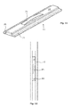
- Fig. 11 shows a stop member 11 for mounting in a side rail 2, 3 as shown in Fig. 4 and Fig. 12 .
- the stop member 11 comprises two flanges 26 and 27 adapted for engaging with tracks 40a and 40b, respectively, of a side rail 2, 3.
- a resilient spring leaf 25 extend from an upper surface 28 of the stop member 11 and when the stop member is mounted in a side rail 2, 3 as shown in Fig. 4 , the leaf spring extends in the in the spacing between the guiding tracks 7 and 30 of the side rail 2, 3, i.e. into the plane in which the screen of wire mesh 4 is operated.
- the operating element 9, 10 of a screen of wire mesh 4 When the operating element 9, 10 of a screen of wire mesh 4 is positioned in an intermediate position as shown in Figs. 1 and 2 , it may be kept in position by a stop member 11. If the operating member 9, 10 is positioned above the stop member 11, the spring leaf 22 will be depressed slightly and thereby the screen of wire mesh 4 is kept more secure in that position. This is in particular useful for installations where the insect screen 1 is mounted so that the screen of wire mesh 4 is to be moved downwards as shown in Fig. 1 and 2 .
- reinforced bands of the screen of wire mesh may be provided as rigid elements connected by joints so that the portion of the screen of wire mesh may still bend or be rolled up for storage when released from the tracks of the side rails.
Landscapes
- Engineering & Computer Science (AREA)
- Structural Engineering (AREA)
- Life Sciences & Earth Sciences (AREA)
- Insects & Arthropods (AREA)
- Pest Control & Pesticides (AREA)
- Architecture (AREA)
- Civil Engineering (AREA)
- Operating, Guiding And Securing Of Roll- Type Closing Members (AREA)
Abstract
Description
- The present invention relates to an insect screen of a building aperture, having a supply condition and a condition of use, comprising first and second side rails extending substantially in parallel to each other in a first longitudinal direction defining, in the condition of use, a height direction, said first longitudinal direction being substantially perpendicular to a second longitudinal direction defining a width direction, a screen of wire mesh with opposing marginal areas in said width direction adapted for being in releasable engagement with said first and second side rails in the condition of use.
- When casement windows are provided with an insect screen at the interior side of the window, the user's access to the operating handle of the window may be impaired. This is specially the case when the insect screen is an insect net used in the summertime where it is also desirable to open and close the window relatively often depending on the time of the day. As an insect net mounted in relation to a window must not leave any opening allowing the user to reach the operating handle of the window, as this would impair the function of the insect net, it is desirable to provide an insect net for a building aperture that is easily removed and repositioned in order to allow the user to operate the window as desired and still have the aperture screened between operation of the window.
-
DE 93 14 022 U1 discloses an insect screen having a screen of insect net adapted for mounting in relation to an aperture of a roof light. An upper rail of the insect screen is fastened with screws to an upper part of the aperture and sides of the apertures are provided with side rails of a magnetic band. Marginal areas of the screen of insect net are provided with a corresponding magnetic band in order to provide a releasable engagement between the side rails and screen of insect net. Hence the screen of insect net may be positioned in either an open or closed position. -
US 4,825,921 discloses a screen assembly having a web of material and a pair of spaced opposed elongate strengthening elements as well as two opposed guide rails and a take-up roll. The strengthening elements are guided on the guide rails such as to enable retraction and withdrawal of the web of material to and from the take-up roll. The strengthening elements are adapted to form a tight roll when rolled up on the take-up roll and are thus resilient in substantially the same way as a coil spring. - It is the object of the present invention to provide an insect screen, which provides for a more flexible adjustment of the screen's position with respect to a building aperture.
- With a view to this the insect screen according to the present invention is characterized in that each of the side rails comprises a track providing a sliding engagement with the opposing marginal areas in the width direction of screen of wire mesh, and the screen of wire mesh is slidably movable in the height direction with respect to the side rails so that a portion of the screen of wire mesh may be released from the engagement with the side rails, the opposing marginal areas in the width direction being reinforced by respective bands extending in the height direction and engaging with respective tracks of the side rails, and particularly in that the screen of wire mesh is flexible in at least the height direction so that a freely hanging portion of the screen of wire mesh released from the engagement with the side rails may bend away from the plane defined by the height direction and the width direction, the screen of wire mesh is resilient in at least the width direction such as to enable a freely hanging portion of the screen of wire mesh released from the engagement with the side rails to remain substantially straight in at least the width direction, and the respective bands are flexible in their longitudinal direction and adapted for being rigid when the bands are located in the respective tracks.
- The provision of tracks in the side rails allows the insect screen to be positioned in many different positions by adjusting the portion of the screen of wire mesh that is released from the engagement with the respective tracks of the side rails. This flexible positioning at any desirable position is achieved by the friction between the opposing marginal areas of the screen of wire mesh and the corresponding tracks of the side rails. Besides from being more flexible in use, the insect screen according to the invention may advantageously be mounted in relation to many different types of windows mounted in a building aperture. Due to the possible flexible positioning of the screen of mesh wire, the insect screen may be used in combination with windows of the type operated by a through-going operating handle in relation to the upper sash part of a roof window, but also with other kinds of casement windows of both the side-hung and top-hung type.
- As the opposing marginal areas in the width direction are reinforced by respective bands extending in the height direction and engaging with respective tracks of the side rails, it becomes possible to provide a screen of wire mesh being of a thinner and more flexible material as the reinforced marginal areas is able to take-up forces during movement of the screen of wire mesh in the tracks of the side rails.
- Besides from taking up forces during movement of the screen of wire mesh, the bands in respective opposing sides of the screens of wire mesh may engage with tracks or grooves of the side rails. Thereby, any tolerances from an imprecise installation of the side rails may be absorbed without impairing the screening of the aperture and the operation of the screen of wire mesh. Furthermore, the bands, which preferably are of a flexible material allowing the screen of wire mesh to be rolled up during transportation, protects the marginal areas both during transportation and during operation against wear and tear.
- As the screen of wire mesh is flexible in at least the height direction, yet resilient in at least the width direction, and as the respective bands are flexible in their longitudinal direction and adapted for being rigid when located in the respective tracks the screen of wire mesh may, when a portion of the wire mesh is hanging freely, be kept in a position not disturbing a user operating the window and simultaneously it becomes very easy for the user to move the freely hanging part of the wires mesh back into the tracks without any risk of jamming or tearing the screen of wire mesh.
- In order to also protect the marginal areas in the height direction of the screen of wire mesh and to facilitate operation of the insect screen, a first marginal area in the height direction of the screen of wire mesh is provided with a first operating element being movable in the height direction. The operating element also entails a proper stretching of the screen of wire mesh between the side rail and that forces applied to the screen of wire mesh is transferred to the reinforced marginal areas engaging with the tracks of the side rails. One or more operating elements guided between the side rails, e.g. by a sliding engagement with tracks of each of the side rails, provides for an improved parallel motion of the marginal areas of the screen of wire mesh with respect to the side rails. As the screen of wire mesh is manually operated by pushing or pulling it in the height direction, the provision of operating elements may further facilitate such movement.
- In a further development of this aspect, a second marginal area in the height direction of the screen of wire mesh is provided with a second operating element being movable in the height direction.
- This further operating element may be of the same type as the first operating element or for instance be of a less prominent size such as a beading serving to protect the edge of the screen of wire mesh and to stretch the screen of wire mesh between the side rails. Evidently, both operating elements may be provided as beadings for protecting and stretching the screen of wire mesh between the side rails. Furthermore, the operating elements at both marginal areas in the height direction of the screen of wire mesh facilitates installation and operation of the insect screen as it's operation is more independent on how the insect screen is mounted.
- In a further developed embodiment, the engagement between the screen of wire mesh and the side rails is releasable in two directions of the height direction. This feature is especially useful when using the insect screen according to the invention for screening apertures of roof windows mounted in an inclined roof, because the distance between the apertures and the floor from which the user is to operate the window and the insect screen varies from building to building. Hence in some installations it is desirable to move the screen of wire mesh upwards in the height direction to access the operating handle of the window, whereas is other installations it is more desirable to move the screen of wire mesh towards the floor in order to provide access to the operating handle. Hence the insect screen according to the invention and it's flexible use may be obtained in connection with many different types of apertures and even in very different types of building structures.
- When the screen of wire mesh is moved downwards, the screen of wire mesh may unintentionally be released from the tracks of the side rails. In order to provide a more failsafe installation, the tracks of the side rails are provided with stop members engaging with the operating members when moved downwards with respect to the height direction. During operation of the insect screen normally only a portion of the screen of wire mesh is to be released from the sliding engagement with the side rails in order to provide the desired flexibility. However, the stop members may also be adapted to engage with the operating members when moved upwards in the height direction.
- In a further embodiment the slidable insect screen further comprises stop members provided at an end of the side rails and at least one element adapted for frictionally engaging the stop members and provided at an end of the screen of wire mesh such that in the use condition of the screening device the stop members and the at least one element adapted for frictionally engaging the stop members are located at the same end of the insect screen.
- The at least one element adapted for frictionally engaging the stop members may be provided on the screen of wire mesh and/or on one of the bands.
- Thereby, the screen of wire mesh is prevented from being removed completely from the side rails during use, thus further simplifying the operation of the insect screen and preventing damage to the screen of wire mesh which might otherwise occur when reinserting it into the side rails.
- In a further developed embodiment of the invention, a guide member extends between the side rails so as to guide the screen of wire mesh when released from the sliding engagement with the side rails.
- The two above-mentioned embodiments provide a more smooth operation of the screen of wire mesh when it is moved with respect to the side rails as it allows the screen of wire mesh to be guided away from the aperture so that the part of screen of wire mesh released from the side rails does not prevent the user to access the operating handle of the window by partly screening the aperture without engaging the tracks of the side rails. Furthermore, the presence of a guide member prevents that the marginal areas are to be guided on any edges on the tracks of the side rails when being released from the sliding engagement. Additionally, the friction between the full width of the screen of wire mesh and the guide member ensures that the screen of wire mesh is kept in any desired position.
- Since the use of an insect screen according to the invention, which serves to prevent insects to enter a building when a building through an open window, is very seasonal, it is desirable that the side rails are releasably mounted on respective mounting rails adapted to receive the side rails. This allows for a dismounting at the end of the season and re-mounting at the beginning of the season in an easy manner without use of any tools.
- In a further development of this embodiment, the guide member is releasably mounted on the side rails so that only the mounting rails are left outside the season when there is no need of an insect screen for keeping insects outside.
- In a further embodiment the insect screen further comprises a stop mechanism, the stop mechanism comprising a first part provided at an end of the side rails and a second part provided at an end of the screen of wire mesh such that in the use condition of the screening device the first part and the second part of the stop mechanism are located at mutually opposite ends of the insect screen.
- The second part of the stop mechanism may be provided on any one or more of the screen of wire mesh, one or both of the bands and the operating member.
- In the following, illustrative examples and embodiments of the present invention are described in further detail with reference to preferred embodiment illustrated by the schematic drawings, on which
-
Fig. 1 is a perspective view of an insect screen according to the invention mounted on a sash of a roof window, -
Fig. 2 is a perspective view of an insect screen according to the invention mounted in relation to an aperture in an inclined roof with a roof window, -
Fig. 3 is a front view of an insect screen according to the invention wherein the screen of wire mesh have been removed, -
Fig. 4 is a perspective view of an insect screen according to the invention in a partly open position, -
Fig. 5 is a perspective view of an insect screen according to the invention in a closed position, -
Fig. 6 is a detailed perspective view of the upper right corner ofFig. 3 , -
Fig. 7 is a detailed perspective bottom view of the insect screen ofFig. 5 , -
Fig. 8 is a perspective view of an embodiment of a side rail according to the invention, -
Fig. 9 is a perspective view of a end stop member according to the invention, -
Fig. 10 is perspective view of a end stop member mounted on a side rail of an insect screen according to the invention, -
Fig. 11 is a perspective view of a stop member according to the invention, -
Fig. 12 is a top view of a stop member mounted in a side rail of an insect screen according to the invention. - In
Fig. 1 is shown aninsect screen 1 according to the invention mounted on asash 51 of a roof window. Theinsect screen 1 comprises a lightweight screen ofwire mesh 4 andside rails wire mesh 4 to thesash 51. The screen ofwire mesh 4 is an insect net adapted to cover an aperture of a window in order to prevent insects, leaves, debris, birds and the like from entering the building while a flow of fresh air into the building is permitted. The screen ofwire mesh 4 may be a wire net of metal, fibreglass and the like synthetic fibres in a mesh or a plastic mesh made from polypropylene, polyethylene, nylon, PVC or PTFE or the like materials. Preferably, the screen ofwire mesh 4 is a PVC coated insect net of fibreglass. In order to facilitate handling of the insect screen in a storage condition, the screen ofwire mesh 4 is preferably made so flexible that it may be rolled up for easier handling during storage outside the season or in a supply condition of theinsect screen 1. - In a condition of use the side rails 2, 3 are mounted substantially in parallel to each other in a first longitudinal direction and defines, in a condition of use as illustrated in
Fig. 1 and2 , a height direction h, which is substantially perpendicular to a second longitudinal direction defining a width direction w. Each of the side rails 2, 3 are provided with a through-goingtrack 7 extending in the height direction h and being adapted to receiverespective margin areas wire mesh 4 in order to provide a sliding engagement betweenside rails wire mesh 4. Hence the side rails 2, 3 serves as side rails mounting the screen ofwire mesh 4 to the aperture to be screened. The friction between themarginal areas wire mesh 4 and therespective tracks 7 of the side rails 2, 3 allows the screen ofwire mesh 4 to be positioned in any desired position along the height direction h. Also, the screen ofwire mesh 4 and the side rails 2, 3 have substantially the same length, size or extension measured in the height direction h. - The sliding engagement between the
side rail wire mesh 4 allows the screen ofwire mesh 4 to be slidable movable in the height direction h with respect to the side rails 2, 3 so that a portion of the screen ofwire mesh 4 may be released from the engagement with therespective tracks 7 of theside rail Fig. 1 where the screen ofwire mesh 4 has been moved downwards with respect to the window installation by pulling an operatingmember 10. Hence a portion of the screen ofwire mesh 4 is freely hanging from the lower portion of the side rails 2, 3 and an upper portion of the aperture or thesash 51 is not covered by screen ofwire mesh 4 so that a operating handle of the window (not shown) located in the upper portion of the sash may be accessed by a user of the window. The screen ofwire mesh 4 is flexible in at least the height direction h so that a freely hanging portion of the screen ofwire mesh 4 released from the engagement with the side rails 2, 3 may bend away from the plane defined by the height direction h and the width direction w. Preferably, the released portion bends away from said plane in a smooth curve so as to reduce friction between theside rail wire mesh 4 is sufficiently resilient in the width direction w to enable a freely hanging portion of the screen ofwire mesh 4 released from the engagement with the side rails 2, 3 to remain substantially straight or unbend in the width direction w. - In order to return to a situation wherein the entire aperture is screened by the screen of
wire mesh 4, the screen ofwire mesh 4 may be pulled upwards by pulling afurther operating handle 9. Evidently, for installations having a different structure or different type of casement and operating handles of thewindow 50, the screen ofwire mesh 4 may be moved upwards in the height direction has shown in principle inFig. 4 , i.e. in the embodiment ofFig. 1 thetracks 7 of the side rails 2, 3 allows the screen ofwire mesh 4 to be released from the sliding engagement in both directions both upwardly and downwardly in the height direction. Hence the insect screen is equally suitable for an aperture with awindow 50 having the operating handle is positioned on a lower portion or on a side portion of thesash 51 and frame. - The operating handles 9, 10 extend between the side rails 2, 3 in the width direction w and are preferably guided in the
tracks 7 of the side rails. Moreover, the provision of operating handles 9, 10 protect the marginal areas in the height direction of the screen ofwire mesh 4 and ensure that the screen ofwire mesh 4 is stretched between the side rails 2, 3. - In
Fig. 2 aninsect screen 1 according to the invention has been mounted in relation to an aperture of aroof window 50 in an inclined roof. Theroof window 50 is shown in an open position and the screen ofwire mesh 4 has been moved downwards with respect to theroof window 50. Due to the dept of the aperture, i.e. the distance between an inner wall of the inclined roof and the frame aperture of theroof window 50, thesash 51 may moved to a position where it is slightly open but which also allows the screen ofwire mesh 4 to be moved upwards in order to screen the entire aperture. This allows a fresh air-flow while the desired screening of the aperture is maintained. In the embodiment ofFig. 2 theinsect screen 1 is provided with aguide member 12 extending between the side rails 2, 3. Theguide member 12 has a tubular or rounded shape and serves to guide the screen ofwire mesh 4 away from the side rails 2, 3. This provides for a smoother operation and protects the screen ofwire mesh 4 from being guided directly on edges of the side rails 2, 3 when a portion of the screen ofwire mesh 4 is released from thetracks 7. In the particular installation ofFig. 2 theguide member 12 is positioned at a lower end with respect to the height direction h between the side rails 2, 3. - For the window installation of
Fig. 2 it is most practical to move the screen ofwire mesh 4 downwardly and therefore theinsect screen 1 is mounted so that theguide member 12 is positioned at the lower end of the side rails 2, 3. When theinsect screen 1 is to be used with another type of window installation having a different structure or having a different type of operating handling on the window, theguide member 12 may be positioned at the upper end of the side rails 2, 3 in order to guide and protect the screen ofwire mesh 4 when moved upwards to be at least partly released from the engagement with the tracks of the side rails 2, 3. Evidently, aguide member 12 may be provided at both ends of theside rail -
Fig. 3 is a front view of aninsect screen 1 with aguide member 12 where the screen ofwire mesh 4 has been removed. Theguide member 12 is connected to one end of theside rail corner fittings 14 and at the opposite end, the side rails 2, 3 is provided withend stop members 15. Hence in this embodiment the screen ofwire mesh 4 is only releasable from the engagement with the side rails 2, 3 at one end of the side rails 2, 3, namely at the end where theguide member 12 is positioned. Furthermore, each of the side rails 2, 3 is provided withstop members 11 which are to be explained in more detail in relation toFig. 11 and 12 . -
Fig. 4 is a perspective view of the insect screen ofFig. 3 showing the screen ofwire mesh 4 in an open position in an embodiment where only oneoperating element 10 is provided at the lower end of the screen ofwire mesh 4. When the screen ofwire mesh 4 is released from the upper end of the side rails 2, 3 it is guided away from the aperture by theguide member 12. InFig. 5 the screen ofwire mesh 4 has been moved to a closed position where the operatingelement 10 is moved as far as possible towards theend stop members 15. -
Fig. 6 is a detailed perspective view of the upper right corner of theinsect screen 1 shown inFig. 3 . The corner fitting 14 is mounted in tracks of the side rail 2 (cf.Fig. 7 ) and comprises a tubular protrusion (not shown) engaging into the tubular shapedguide member 12. During movement of the screen ofwire mesh 4 it is guided between theguide member 12 and the main body portion of the corner fitting 14 extending in the height direction of theside rail 2. Evidently, the guide member may comprise two portions, e.g. two rounded members adapted so that the screen ofwire mesh 4 is to be guided in between them. Preferably, the engagement between theguide member 12 and the corner fittings is provided as snap connection so that theguide member 12, the screen ofwire mesh 4 and theoperating elements -
Fig. 7 is a detailed perspective view of the lower left corner of theinsect screen 1 ofFig. 5 , wherein the operatingelement 10 and theend stop members 15 have been removed. Afirst track 40a and asecond track 40b extending in the full length of theside rail 3 in the height direction h is used for mounting a corner fitting 14, stop members (cf.Fig. 12 ) and end stop members (cf.Fig. 10 ). At the distal end of theside rail 3 ofFig. 7 , the corner fitting 14 is mounted in thetracks guide member 12 is mounted to the corner fitting 14. Similar tracks are provided in theside rail 2 of the other side of theinsect screen 1. - In the embodiment of
Fig. 7 themarginal area 6 of the screen ofwire mesh 4 is guided in afirst guide track 7 also extending the height direction h of theside rail 3. Furthermore, themarginal area 6 in the width direction w of the screen ofwire mesh 4 is reinforced with aband 8 extending along the edge in the height direction h. Theband 8 is flexible in its longitudinal direction so that the screen ofwire mesh 4 may still be rolled up to provide a storage condition which is easy to handle, but when thebands 8 in each side of the screen ofwire mesh 4 is located inguide tracks operating elements band 8 is flexible in its longitudinal direction and adapted for, in practice, being rigid or function as a bar-like element when it is located inguide tracks band 8 is not resilient. Afirst portion 8a of theflexible band 8 is fastened to the screen ofwire mesh 4 along the edge in the height direction h by gluing, adhering or welding and is disposed in thefirst guide track 7. Asecond portion 8b of theflexible band 8, which is not fastened to the screen ofwire mesh 4, is in this particular embodiment disposed in asecond guide track 30 opposing thefirst guide track 7. Preferably, theflexible band 8 is made of PVC. The provision of opposingguide tracks flexible band 8 fastened to marginal areas of the screen ofwire mesh 4, ensure that tolerances due to an imprecise mounting of the side rails 2, 3 with respect to the aperture may be compensated for by providing a slack between theflexible band 8 and the guide tracks 7 and 30. - Alternatively, the screen of
wire mesh 4 is reinforced in themarginal areas first guide track 7 is used to provide the sliding engagement between the screen ofwire mesh 4 and the side rails 2, 3. The reinforced portions of the screen ofwire mesh 4 or thebands 8 are more rigid than the remaining portion of the screen ofwire mesh 4, which allows a portion of the screen ofwire mesh 4 released from the engagement with the side rails 2, 3 to bend way from the plane defined by the height direction h and the width direction w in a smooth curve. This allows for use of a very lightweight and even more flexible screen ofwire mesh 4, while the operation of the screen ofwire mesh 4 is improved due to the reinforcedmarginal areas wire mesh 4 is moved with respect to the side rails 2, 3. Hence, reinforced portions or thebands 8 are flexible when released from an engagement with the side rails 2, 3 but still able to take up forces in the height direction h when guided in a track of the side rail. Furthermore, the side rails 2, 3 may take many different shapes in order to provide the desired means for fixingcorner fittings 14,end stop members 15, stopmembers 11, and to provide the sliding engagement with the screen ofwire mesh 4. -
Fig. 8 is a perspective view of aside rail 3 of an insect screen according to another embodiment of the invention. In this embodiment, the side rails 2, 3 are mounted to an aperture by use of mountingrails 13 adapted to engage with the back side of the side rails 2, 3 facing the aperture and being adapted to be mounted on a mountingrail 13 e.g. by a means of a snap connection that does not require any tools for mounting or dismounting. Instead of using mounting rails the side rails 2, 3 may be mounted directly to an aperture by means of screws or suitable fastening means. -
Fig. 9 is a perspective view of anend stop member 15 to be mounted at an end of aside rail 2 of aninsect screen 1 according to the invention. Theend stop member 15 comprises abody portion 23 for closing off the end of aside rail body portion 23 twoflanged coupling members coupling members tracks side rail 2 as shown inFig. 10 . Between the coupling members aresilient leaf spring 22 is positioned so that when the coupling members engages with thetracks Fig. 10 the leaf spring extend in the in the spacing between the guidingtracks wire mesh 4 is operated. - When the screen of
wire mesh 4 is positioned in a closed position as shown inFig. 5 , thespring leaf 22 will be slightly depressed by anoperating element spring leaf 22 and thereby the screen ofwire mesh 4 is kept more secure in that position. This is especially the case when theinsect screen 1 is mounted so that the screen ofwire mesh 4 is to be moved downwards as shown inFig. 1 and2 . If the friction between thetracks margin areas wire mesh 4 is reduced over time due to wear and tear, the provision of aend stop member 15 keeping the screen ofwire mesh 4 in the closed position, will make sure that the overall functionality of theinsect screen 1 is not impaired. Furthermore, theend stop member 15 will ensure that the screen ofwire mesh 4 is kept in the closed position even in case of strong gusts of wind. -
Fig. 11 shows astop member 11 for mounting in aside rail Fig. 4 andFig. 12 . Thestop member 11 comprises twoflanges tracks side rail resilient spring leaf 25 extend from anupper surface 28 of thestop member 11 and when the stop member is mounted in aside rail Fig. 4 , the leaf spring extends in the in the spacing between the guidingtracks side rail wire mesh 4 is operated. - When the
operating element wire mesh 4 is positioned in an intermediate position as shown inFigs. 1 and2 , it may be kept in position by astop member 11. If the operatingmember stop member 11, thespring leaf 22 will be depressed slightly and thereby the screen ofwire mesh 4 is kept more secure in that position. This is in particular useful for installations where theinsect screen 1 is mounted so that the screen ofwire mesh 4 is to be moved downwards as shown inFig. 1 and2 . If the friction between thetracks margin areas wire mesh 4 due to wear and tear is reduced over time, the provision of astop members 11 at the side rails 2, 3, will make sure that screen ofwire mesh 4 is not unintentionally fully released from thetracks leaf spring 25 may be overcome so that the screen ofwire mesh 4 andcorresponding operating elements - The various embodiments described above may be combined into other embodiments, and it is furthermore possible to design specific features in other manner within the scope of the claims. As an example the reinforced bands of the screen of wire mesh may be provided as rigid elements connected by joints so that the portion of the screen of wire mesh may still bend or be rolled up for storage when released from the tracks of the side rails.
Claims (11)
- An insect screen (1) of a building aperture, having a supply condition and a condition of use, comprising
first and second side rails (2, 3) extending substantially in parallel to each other in a first longitudinal direction defining, in the condition of use, a height direction (h), said first longitudinal direction being substantially perpendicular to a second longitudinal direction defining a width direction (w),
a screen of wire mesh (4) with opposing marginal areas (5, 6) in said width direction (w) adapted for being in releasable engagement with said first and second side rails (2, 3) in the condition of use,
each of the side rails (2, 3) comprising a track (7) providing a sliding engagement with the opposing marginal areas (5, 6) in the width direction (w) of the screen of wire mesh (4),
the screen of wire mesh (4) being slidably movable in the height direction (h) with respect to the side rails (2, 3) so that a portion of the screen of wire mesh (4) may be released from the engagement with the side rails (2, 3),
the opposing marginal areas (5, 6) in the width direction (w) being reinforced by respective bands (8) extending in the height direction (h) and engaging with respective tracks (7) of the side rails (2, 3),
characterized in that
the screen of wire mesh (4) is flexible in at least the height direction (h) so that a freely hanging portion of the screen of wire mesh (4) released from the engagement with the side rails (2, 3) may bend away from the plane defined by the height direction (h),
the width direction (w) and the screen of wire mesh (4) is resilient in at least the width direction (w) such as to enable a freely hanging portion of the screen of wire mesh (4) released from the engagement with the side rails (2, 3) to remain substantially straight in at least the width direction (w), and
the respective bands (8) are flexible in their longitudinal direction and adapted for being rigid when the bands (8) are located in the respective tracks (7). - An insect screen (1) according to claim 1, wherein a first marginal area in the height direction (h) of the screen of wire mesh (4) is provided with a first operating element (9) being movable in the height direction (h).
- An insect screen (1) according to claim 2, wherein a second marginal area in the height direction (h) of the screen of wire mesh (4) is provided with a second operating element (10) being movable in the height direction (h).
- An insect screen (1) according to any one of claims 1 to 3, wherein the engagement between the screen of wire mesh (4) and the side rails (2, 3) is releasable in two directions of the height direction (h).
- An insect screen (1) according to any previous claim, and further comprising stop members (11) provided at an end of the side rails (2, 3) and at least one element adapted for frictionally engaging the stop members (11) and provided at an end of the screen of wire mesh (4) such that in the use condition of the screening device the stop members (11) and the at least one element adapted for frictionally engaging the stop members (11) are located at the same end of the insect screen (1).
- An insect screen (1) according to claim 5, wherein the tracks (7) of the side rails (2, 3) are provided with the stop members (11), and wherein the stop members (11) are frictionally engaging the operating elements (9, 10) when moved downwards with respect to the height direction (h).
- An insect screen (1) according to any previous claim, wherein a guide member (12) extends between the side rails (2, 3) so as to guide the screen of wire mesh (4) when released from the sliding engagement with the side rails (2, 3).
- An insect screen (1) according to any previous claim, wherein the side rails (2, 3) are releasably mounted on respective mounting rails (13) adapted to receive the side rails (2, 3).
- An insect screen (1) according to claim 7 or 8, wherein the guide member (12) is releasably mounted on the side rails (2, 3).
- An insect screen (1) according to any previous claim, and further comprising a stop mechanism, the stop mechanism comprising a first part provided at an end of the side rails (2, 3) and a second part provided at an end of the screen of wire mesh (4) such that in the use condition of the screening device the first part and the second part of the stop mechanism are located at mutually opposite ends of the insect screen (1).
- An insect screen according to claim 10, wherein the first part of the stop mechanism is a guide member (12) and the second part of the stop mechanism is an operating element (9, 10).
Applications Claiming Priority (1)
| Application Number | Priority Date | Filing Date | Title |
|---|---|---|---|
| DKPA201370777 | 2013-12-16 |
Publications (1)
| Publication Number | Publication Date |
|---|---|
| EP2884039A1 true EP2884039A1 (en) | 2015-06-17 |
Family
ID=52282377
Family Applications (1)
| Application Number | Title | Priority Date | Filing Date |
|---|---|---|---|
| EP14020109.6A Withdrawn EP2884039A1 (en) | 2013-12-16 | 2014-12-10 | Slidable insect screen of a building aperture |
Country Status (1)
| Country | Link |
|---|---|
| EP (1) | EP2884039A1 (en) |
Citations (2)
| Publication number | Priority date | Publication date | Assignee | Title |
|---|---|---|---|---|
| FR751308A (en) * | 1932-03-02 | 1933-08-31 | Louver | |
| US4825921A (en) * | 1986-05-07 | 1989-05-02 | Rigter Steven M | Blinds, screens, partitions and doors |
-
2014
- 2014-12-10 EP EP14020109.6A patent/EP2884039A1/en not_active Withdrawn
Patent Citations (2)
| Publication number | Priority date | Publication date | Assignee | Title |
|---|---|---|---|---|
| FR751308A (en) * | 1932-03-02 | 1933-08-31 | Louver | |
| US4825921A (en) * | 1986-05-07 | 1989-05-02 | Rigter Steven M | Blinds, screens, partitions and doors |
Similar Documents
| Publication | Publication Date | Title |
|---|---|---|
| US7472738B2 (en) | Screen device | |
| EP2317062B1 (en) | A blind system | |
| CN107075903B (en) | Retrofit retractable screen system | |
| CN1860280B (en) | Horizontal screen window | |
| US20140041814A1 (en) | Roller assembly and guide for a retractable screen | |
| EP1333148A2 (en) | A rolling mosquito net for frames provided with foldaway guides | |
| US20110227371A1 (en) | Sunshade assembly and open roof construction provided therewith | |
| US6691465B1 (en) | Door closer assembly for sliding doors | |
| AU2010241510A1 (en) | A retractable screen | |
| JP2016028182A (en) | Attachment structure of water stop panel | |
| KR20130104388A (en) | Mothproof screen apparatus for sliding window | |
| EP2236731B1 (en) | Covering arrangement for architectural openings | |
| JP6126898B2 (en) | sash | |
| US8656979B2 (en) | Pet door pest and debris barrier | |
| JP2005023578A (en) | End part guide of storable stretching surface member | |
| JP6952324B2 (en) | Insect repellent net for vehicles | |
| JP5420291B2 (en) | Building opening screen device | |
| EP4077862B1 (en) | Roller screen with improved handle portion | |
| US20050178510A1 (en) | Shutter device with guideways | |
| EP4077861B1 (en) | Roller screen with a set of connection elements | |
| EP4077864B1 (en) | A roller screen, in particular an insect net | |
| JP4263633B2 (en) | Shutter device | |
| AU2012101911A4 (en) | Roller assembly and guide for a retractable screen | |
| KR102497565B1 (en) | Position variable winding window screen unit | |
| KR102245728B1 (en) | Door frame cover |
Legal Events
| Date | Code | Title | Description |
|---|---|---|---|
| PUAI | Public reference made under article 153(3) epc to a published international application that has entered the european phase |
Free format text: ORIGINAL CODE: 0009012 |
|
| 17P | Request for examination filed |
Effective date: 20141210 |
|
| AK | Designated contracting states |
Kind code of ref document: A1 Designated state(s): AL AT BE BG CH CY CZ DE DK EE ES FI FR GB GR HR HU IE IS IT LI LT LU LV MC MK MT NL NO PL PT RO RS SE SI SK SM TR |
|
| AX | Request for extension of the european patent |
Extension state: BA ME |
|
| R17P | Request for examination filed (corrected) |
Effective date: 20151217 |
|
| RBV | Designated contracting states (corrected) |
Designated state(s): AL AT BE BG CH CY CZ DE DK EE ES FI FR GB GR HR HU IE IS IT LI LT LU LV MC MK MT NL NO PL PT RO RS SE SI SK SM TR |
|
| STAA | Information on the status of an ep patent application or granted ep patent |
Free format text: STATUS: THE APPLICATION IS DEEMED TO BE WITHDRAWN |
|
| 18D | Application deemed to be withdrawn |
Effective date: 20151218 |