EP2884014A1 - Toilet with throttle to limit the flow rate of flushing water - Google Patents
Toilet with throttle to limit the flow rate of flushing water Download PDFInfo
- Publication number
- EP2884014A1 EP2884014A1 EP14196965.9A EP14196965A EP2884014A1 EP 2884014 A1 EP2884014 A1 EP 2884014A1 EP 14196965 A EP14196965 A EP 14196965A EP 2884014 A1 EP2884014 A1 EP 2884014A1
- Authority
- EP
- European Patent Office
- Prior art keywords
- water
- throttle member
- bowl
- cross
- rim
- Prior art date
- Legal status (The legal status is an assumption and is not a legal conclusion. Google has not performed a legal analysis and makes no representation as to the accuracy of the status listed.)
- Withdrawn
Links
- XLYOFNOQVPJJNP-UHFFFAOYSA-N water Substances O XLYOFNOQVPJJNP-UHFFFAOYSA-N 0.000 title claims abstract description 427
- 238000011010 flushing procedure Methods 0.000 title 1
- 239000002699 waste material Substances 0.000 claims abstract description 37
- 238000011144 upstream manufacturing Methods 0.000 claims description 40
- 230000007423 decrease Effects 0.000 claims description 15
- 238000004140 cleaning Methods 0.000 abstract description 26
- 239000012530 fluid Substances 0.000 description 6
- 238000009434 installation Methods 0.000 description 3
- 230000033228 biological regulation Effects 0.000 description 2
- 238000010586 diagram Methods 0.000 description 2
- 230000000694 effects Effects 0.000 description 2
- 239000004743 Polypropylene Substances 0.000 description 1
- 239000000853 adhesive Substances 0.000 description 1
- 230000001070 adhesive effect Effects 0.000 description 1
- 239000000919 ceramic Substances 0.000 description 1
- 238000007599 discharging Methods 0.000 description 1
- 239000000463 material Substances 0.000 description 1
- -1 polypropylene Polymers 0.000 description 1
- 229920001155 polypropylene Polymers 0.000 description 1
- 239000011347 resin Substances 0.000 description 1
- 229920005989 resin Polymers 0.000 description 1
- 230000000630 rising effect Effects 0.000 description 1
- 239000008400 supply water Substances 0.000 description 1
- 230000007704 transition Effects 0.000 description 1
Images







Classifications
-
- E—FIXED CONSTRUCTIONS
- E03—WATER SUPPLY; SEWERAGE
- E03D—WATER-CLOSETS OR URINALS WITH FLUSHING DEVICES; FLUSHING VALVES THEREFOR
- E03D11/00—Other component parts of water-closets, e.g. noise-reducing means in the flushing system, flushing pipes mounted in the bowl, seals for the bowl outlet, devices preventing overflow of the bowl contents; devices forming a water seal in the bowl after flushing, devices eliminating obstructions in the bowl outlet or preventing backflow of water and excrements from the waterpipe
- E03D11/13—Parts or details of bowls; Special adaptations of pipe joints or couplings for use with bowls, e.g. provisions in bowl construction preventing backflow of waste-water from the bowl in the flushing pipe or cistern, provisions for a secondary flushing, for noise-reducing
- E03D11/17—Means for connecting the bowl to the flushing pipe
-
- E—FIXED CONSTRUCTIONS
- E03—WATER SUPPLY; SEWERAGE
- E03D—WATER-CLOSETS OR URINALS WITH FLUSHING DEVICES; FLUSHING VALVES THEREFOR
- E03D11/00—Other component parts of water-closets, e.g. noise-reducing means in the flushing system, flushing pipes mounted in the bowl, seals for the bowl outlet, devices preventing overflow of the bowl contents; devices forming a water seal in the bowl after flushing, devices eliminating obstructions in the bowl outlet or preventing backflow of water and excrements from the waterpipe
- E03D11/02—Water-closet bowls ; Bowls with a double odour seal optionally with provisions for a good siphonic action; siphons as part of the bowl
- E03D11/06—Bowls with downwardly-extending flanges for the sake of flushing
-
- E—FIXED CONSTRUCTIONS
- E03—WATER SUPPLY; SEWERAGE
- E03D—WATER-CLOSETS OR URINALS WITH FLUSHING DEVICES; FLUSHING VALVES THEREFOR
- E03D9/00—Sanitary or other accessories for lavatories ; Devices for cleaning or disinfecting the toilet room or the toilet bowl; Devices for eliminating smells
- E03D9/16—Water pressure regulating means in flushing pipes
Definitions
- the present invention relates to flush toilets, and more specifically, it relates to a wash-down flush toilet that cleans a bowl body and discharges waste using wash water supplied from a wash-water supply source.
- wash water held in a water tank is ejected in the horizontal direction from a rim outlet to form a swirl flow for facilitating cleaning.
- water tanks installed on a wall distant from a toilet bowl are known. Such water tanks are classified into three types depending on the height at which the water tanks are installed: a low-position type, an intermediate-position type, and a high-position type. An appropriate type of water tank is selected from these types in accordance with the installation site and connected to the toilet bowl. Since these three types of water tanks are installed at different heights, the distance of elevation between each water tank and the toilet bowl differs between the water tanks and thus the flow rate at which the water tank supplies water to the toilet bowl also differs between the water tanks.
- wash water that whirls around a rim portion having an inner circumferential surface shaped so as to overhang or extend substantially vertically would flow over the rim portion out of the bowl body.
- wash water that whirls around the rim portion is more likely to overflow at areas of the rim portion having small radii of curvature, which are front and rear areas, and at a transition area from the front to a side.
- the design of a water conduit of the bowl body may be changed so as to increase the pressure loss and reduce the flow rate at which water is supplied. In this case, the wash water can be prevented from overflowing from the rim portion of the bowl body to which the high-position water tank is connected. If, on the other hand, a low-position water tank, which supplies water at a low flow rate, is connected to the bowl body, the flow rate of wash water that whirls around the rim portion would be insufficient to fully clean the bowl portion of the bowl body.
- the present invention is made to solve the above-described existing problems and aims to provide a flush toilet that can supply wash water to a bowl portion of a bowl body at a flow rate appropriate for cleaning the bowl body regardless of whichever water tank that supplies water at any of different flow rates is connected to the bowl body.
- the present invention provides a flush toilet that cleans the toilet and discharges waste.
- the flush toilet includes a water tank that holds wash water and a bowl body.
- the bowl body includes a bowl portion, a drain, a rim water-ejecting portion, and a water conduit.
- the bowl portion includes a bowl-shaped waste receiving surface and a rim portion formed at an upper edge of the waste receiving surface and having an inner circumferential surface shaped so as to overhang or extend substantially vertically.
- the drain has an inlet connected to a lower portion of the bowl portion and allows waste to be discharged therethrough.
- the rim water-ejecting portion is formed in the inner circumferential surface of the rim portion and forms a swirl flow by ejecting wash water.
- the water conduit guides the wash water held in the water tank to the rim water-ejecting portion.
- a throttle member is attached to the water conduit.
- the throttle member is capable of adjusting a cross-sectional area of a water-flow passage of the water conduit so that the cross-sectional area decreases as the wash water is supplied from the water tank at a higher flow rate.
- the throttle member is attached to the water conduit, and the throttle member can adjust the cross-sectional area of the water-flow passage of the water conduit so as to reduce the cross-sectional area of the water-flow passage of the water conduit as the flow rate of wash water supplied from the water tank increases.
- the flush toilet can supply wash water to the bowl portion at a flow rate appropriate for cleaning the bowl portion regardless of whichever water tank that supplies water at any of different flow rates is connected to the bowl body.
- the wash water that whirls around the rim portion can be prevented from flowing over the rim portion out of the bowl body.
- this structure can prevent the wash water from failing to fully clean the inside of the bowl portion due to an insufficient force of the wash water whirling around the rim portion caused by an insufficient flow rate of wash water ejected from the rim outlet.
- the bowl body includes a jet ejection portion that ejects the wash water from a jet outlet of the jet ejection portion that is open at a side portion of the waste receiving surface of the bowl portion, and the water conduit is split so as to extend to the jet ejection portion of the bowl body.
- the water conduit has a small-diameter portion at an upstream-side portion of the water conduit.
- the small-diameter portion has a water-flow passage having a cross-sectional area smaller than the sum of a cross-sectional area of the jet outlet of the jet ejection portion and a cross-sectional area of an outlet of the rim water-ejecting portion.
- the throttle member is removably attached to the small-diameter portion, and the cross-sectional area of the water-flow passage of the small-diameter portion is changeable by replacing the throttle member with another throttle member.
- the small-diameter portion has a water-flow passage having a cross-sectional area on the upstream side of the water conduit.
- the cross-sectional area of the water-flow passage is smaller than the sum of the cross-sectional area of the jet outlet and the cross-sectional area of the rim outlet.
- the cross-sectional area of the water-flow passage of the small-diameter portion can be changed by replacing the throttle member with another throttle member.
- the throttle member can adjust the maximum pressure loss received by the wash water passing through the water conduit, whereby the wash water can be supplied to the bowl portion at a flow rate appropriate for cleaning the bowl portion regardless of whichever water tank that supplies water at any of different flow rates is connected to the bowl body.
- the water conduit has a small-diameter portion at an upstream-side portion of the water conduit, and the small-diameter portion has a water-flow passage having a cross-sectional area smaller than the sum of cross-sectional areas of outlets of the rim water-ejecting portion.
- the throttle member is removably attached to the small-diameter portion, and the cross-sectional area of the water-flow passage of the small-diameter portion is changeable by replacing the throttle member with another throttle member.
- the small-diameter portion disposed at an upstream-side portion of the water conduit has a water-flow passage having a cross-sectional area smaller than the sum of cross-sectional areas of outlets of the rim water-ejecting portion.
- the throttle member forms a passage extending a predetermined length in a direction in which wash water flows, and the throttle member tapers so that a cross-sectional area of a water-flow passage of the throttle member gradually decreases from an upstream end to a downstream end.
- the throttle member tapers so that its cross-sectional area of the water-flow passage gradually decreases from the upstream end to the downstream end, whereby wash water passing through the throttle member can be prevented from forming turbulence and the throttle member facilitates an adjustment of the maximum pressure loss that the wash water receives.
- the throttle member since the throttle member has a water-flow passage having a smallest cross-sectional area at the downstream end, the throttle member can adjust the maximum pressure loss received by the wash water passing through the downstream end.
- wash water can be supplied to the bowl portion at a flow rate appropriate for cleaning the bowl portion regardless of whichever water tank that supplies water at any of different flow rates is connected to the bowl body.
- the cross-sectional area of the water-flow passage of the throttle member at the upstream end is substantially the same as a cross-sectional area of a water-flow passage of a water-supply connecting pipe connected to an upstream-side portion of the throttle member
- a cross-sectional shape of the water-flow passage of the throttle member at the upstream end is substantially the same as a cross-sectional shape of the water-flow passage of the water-supply connecting pipe
- an axis of the throttle member and an axis of the water-supply connecting pipe at a connection portion are substantially aligned with each other.
- the flush toilet according to the present invention having the above-described structure can regulate the pressure loss received by the wash water that flows into the throttle member from the water-supply connecting pipe, whereby the throttle member facilitates the regulation of the pressure loss.
- wash water can be supplied to the bowl portion at a flow rate appropriate for cleaning the bowl portion regardless of whichever water tank that supplies water at any of different flow rates is connected to the bowl body.
- a gap having a predetermined dimension is left between an outer circumferential surface of the throttle member facing outward and an inner circumferential surface of the small-diameter portion of the bowl body facing inward.
- the throttle member can be easily attached to the small-diameter portion of the bowl body that would have dimensional deviation.
- the throttle member includes a plurality of protrusions disposed on an outer circumferential surface at predetermined intervals on a circumference of the outer circumferential surface, each of the protrusions has, at a top portion, a taper surface that is inclined downward from an inner side to an outer side, and the taper surface comes into contact with the small-diameter portion of the bowl body.
- each protrusion has a taper surface on the outer circumferential surface of the throttle member and the taper surface comes into contact with the small-diameter portion of the bowl body.
- the axis of the throttle member can be aligned with the axis of the small-diameter portion when the throttle member is pressed against the small-diameter portion by the water pressure, whereby the center of the throttle member can be reliably aligned.
- the throttle member includes a hook portion hooked on a downstream-side portion of the small-diameter portion.
- the throttle member includes a hook portion hooked on a downstream side portion of the small-diameter portion.
- a flush toilet that cleans the toilet and discharges waste includes a water tank that holds wash water and a bowl body.
- the bowl body includes a bowl portion, a drain, a rim water-ejecting portion, and a water conduit.
- the bowl portion includes a bowl-shaped waste receiving surface and a rim portion formed at an upper edge of the waste receiving surface and having an inner circumferential surface shaped so as to overhang or extend substantially vertically.
- the drain has an inlet connected to a lower portion of the bowl portion and allows waste to be discharged therethrough.
- the rim water-ejecting portion is formed in the inner circumferential surface of the rim portion and forms a swirl flow by ejecting wash water.
- the water conduit guides the wash water held in the water tank to the rim water-ejecting portion.
- a throttle member is attached to the water conduit.
- the throttle member is capable of adjusting a cross-sectional area of a water-flow passage of the water conduit so that the cross-sectional area decreases as the wash water is supplied from the water tank at a higher flow rate.
- the throttle member is a member different from the bowl body and removable from the bowl body. The throttle member is removed when the flow rate of the wash water supplied from the water tank is smaller than a predetermined flow rate.
- the flush toilet according to the present invention having the above-described structure can exclude a throttle member by removing the throttle member from the water conduit when the flow rate at which water is supplied from the water tank is smaller than a predetermined rate, the throttle member being capable of adjusting the cross-sectional area of the water-flow passage of the water conduit so as to reduce the cross-sectional area of the water-flow passage of the water conduit as the flow rate at which water is supplied from the water tank increases.
- the flush toilet can supply wash water to the bowl portion at a flow rate appropriate for cleaning the bowl portion even when a water tank that supplies water at a relatively low flow rate is connected to the bowl body.
- the bowl body including the bowl portion including a rim portion having an inner circumferential surface shaped so as to overhang or extend substantially vertically can prevent the wash water from failing to fully clean the inside of the bowl portion due to an insufficient force of the wash water whirling around the rim portion caused by an insufficient flow rate of the wash water ejected from the rim outlet.
- the flush toilet according to the present invention having the above-described structure can supply wash water to a bowl portion of a bowl body at a flow rate appropriate for cleaning the bowl portion regardless of whichever water tank that supplies water at any of different flow rates is connected to the bowl body.
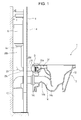
- FIG. 1 is a schematic diagram of a flush toilet 1 according to a first embodiment of the present invention including a high-position water tank and installed on a wall surface.
- the flush toilet 1 is a wash-down flush toilet (wash-down toilet) that discharges waste using a difference of elevation due to rising of the water level of water accumulated in a trapway, described below.
- the flush toilet may be another type of a toilet, such as a siphon toilet.
- the flush toilet 1 includes a ceramic bowl body 2, which is installed on a wall 4. Behind the wall 4, a water tank (a so-called high-position water tank) 6 that holds wash water is installed at a relatively high height (for example, at which the overall height is approximately 1120 mm from the floor).
- the water tank 6 is connected to a wash-water supply source (not illustrated) such as a water supply line.
- a wash-water supply source not illustrated
- an operation switch 8 is attached to the surface of the wall 4. When the operation switch 8 is turned on, wash water held in the water tank 6 is supplied to the bowl body 2 to clean the bowl body 2.
- a drainpipe 10 for discharging waste is installed.
- the drainpipe 10 allows waste to be discharged from the bowl body 2 to the outside.
- the water tank 6 of the flush toilet 1 is a water tank concealed behind the wall 4, the water tank may be installed in front of the wall.
- the flush toilet 1 includes a high-position water tank as the water tank 6.
- Another water tank is also selectable, in accordance with the height at which the water tank is installed, from among, for example, three different types of water tanks: a high-position water tank installed at a relatively high height at which the overall height of the water tank is approximately 1120 mm from the floor; a low-position water tank installed at a relatively low height at which the overall height of the water tank is approximately 820 mm from the floor; and an intermediate-position water tank installed at an intermediate height between the relatively high height and the relatively low height at which the overall height of the water tank is approximately 980 mm from the floor.
- Such a water tank may be installed in combination with a new bowl body, a water tank already installed at the site may be used in combination with a newly installed bowl body, or a water tank may be replaced with a new one after a bowl body has been installed.
- FIG. 2 is a plan view of the flush toilet 1 according to the first embodiment of the present invention.
- Fig. 3 is a cross-sectional side view of a portion of the flush toilet 1 taken along the line III-III of Fig. 2 .
- the bowl body 2 of the flush toilet 1 includes a bowl portion 12 and a trapway 14 extending continuously with a bottom portion of the bowl portion 12.
- the bowl portion 12 includes a waste receiving surface 16 and a rim portion 18 at an upper edge of the waste receiving surface 16.
- the rim portion 18 has an inner circumferential surface shaped so as to overhang or extend substantially vertically.
- the rim portion 18 is shaped so as to overhang or extend substantially vertically and smoothly upright continuously with the upper edge of the waste receiving surface 16.
- the waste receiving surface 16 of the bowl portion 12 includes a bowl-shaped upper waste-receiving surface 20 and a recessed portion 22 formed between the upper waste-receiving surface 20 and the trapway 14.
- the trapway 14 extends obliquely upward from an inlet 14a that is open in the bottom portion of the bowl portion 12, bends at the uppermost point 14b, and extends obliquely downward until arriving at an outlet 14c, at which the trapway 14 is connected to the above-described drainpipe 10 (see Fig. 1 ).
- the water level L of water accumulated in the flush toilet 1 is flush with the uppermost point 14b of the trapway 14.
- the flush toilet 1 includes a water conduit 23 including a water-supply connecting pipe 25 that extends from an outlet 6a of the water tank 6 to an inlet 24a of the bowl body 2.
- the flush toilet 1 extends to the inside of the bowl body 2.
- the water conduit 23 also includes a bowl-body water-flow passage 24 extending to a rear portion of the inside of the bowl body 2.
- the water-supply connecting pipe 25 includes an upstream water-supply connecting pipe 25b, extending vertically downward from the outlet 6a of the water tank 6, and a downstream water-supply connecting pipe 25d, extending from an outlet 25c of the upstream water-supply connecting pipe 25b to the inlet 24a of the inside of the bowl body 2.
- the bowl-body water-flow passage 24 includes a common water-flow passage 24b, a jet water-flow passage 24c, and a rim water-flow passage 24d.
- the common water-flow passage 24b extends from the inlet 24a of the bowl-body water-flow passage 24, connected to the outlet 25a of the water-supply connecting pipe 25 extending from the water tank 6, to the vicinity of a rear portion of the bowl portion 12.
- the jet water-flow passage 24c branches off from the common water-flow passage 24b at the vicinity of a rear portion of the bowl portion 12.
- the common water-flow passage 24b receives wash water from the water tank 6.
- a rim outlet 26 is formed at a front left portion on the inner circumferential side of the rim portion 18 when the bowl body 2 is viewed from the front.
- the above-described rim water-flow passage 24d extends to the rim outlet 26, to which wash water is supplied. From the rim outlet 26, wash water is ejected forward and forms a swirl flow inside the bowl portion 12.
- a jet outlet 28 is formed at a substantially middle portion on the left side (a side) of the waste receiving surface 16 of the bowl portion 12 when the bowl portion 12 is viewed from the front.
- the jet outlet 28 is formed above the water surface W0.
- the jet outlet 28 is connected with the jet water-flow passage 24c branching off from the common water-flow passage 24b of the bowl-body water-flow passage 24.
- a mainstream of wash water ejected from the jet outlet 28 flows into the water (water surface W0) accumulated in the recessed portion 22 and then whirls.
- a small-diameter portion 24e at which the diameter of a water-flow passage is reduced is formed at the inlet 24a of the bowl-body water-flow passage 24.
- the small-diameter portion 24e defines a circular opening and allows a cylindrical throttle member 30 to be fitted to the inner circumferential side of the small-diameter portion 24e.
- the cross-sectional area C1 of a water flow (cross-sectional area of a water-flow passage) of the small-diameter portion 24e is determined so as to be larger than the cross-sectional area of the water-flow passage of the water-supply connecting pipe 25 but smallest throughout the cross-sectional area of the water-flow passage of the bowl-body water-flow passage 24.
- the small-diameter portion 24e When the throttle member 30 is fitted to the small-diameter portion 24e, the small-diameter portion 24e has a water-flow passage having a smallest cross-sectional area throughout the water-supply connecting pipe 25 and the bowl-body water-flow passage 24.
- the cross-sectional area C1 of the water-flow passage of the small-diameter portion 24e is smaller than the sum of the cross-sectional area C2 of the water-flow passage of the jet outlet 28 and the cross-sectional area C3 of the water-flow passage of the rim outlet 26.
- the cross-sectional area C1 of the water-flow passage of the small-diameter portion 24e determines, or the cross-sectional area C5 of the water-flow passage of the downstream end 30d of the throttle member 30 when inserted into the small-diameter portion 24e, determines the flow rate of wash water flowing through the bowl-body water-flow passage 24.
- the small-diameter portion 24e forms a water-flow passage at the inlet 24a of the bowl-body water-flow passage 24.
- the cross-sectional area of the water-flow passage of the small-diameter portion is determined to be smaller than the cross-sectional area of the water-flow passage of the rim outlet or the sum of the cross-sectional areas of the water-flow passages of the rim outlets.
- the cross-sectional area of the water-flow passage of the small-diameter portion is determined to be smaller than the cross-sectional area of the water-flow passage of the rim outlet.
- the cross-sectional area of the water-flow passage of the small-diameter portion 24e is determined to be smaller than the sum of the cross-sectional areas of the water-flow passages of the two rim outlets.
- Fig. 4 is an enlarged cross-sectional view of an inlet B of the bowl-body water-flow passage 24 of the flush toilet 1 according to the first embodiment of the present invention illustrated in Fig. 1 .
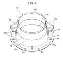
- Fig. 5 is a perspective view of a throttle member 30 of the flush toilet 1 according to the first embodiment of the present invention, viewed obliquely from above.
- Fig. 6 is a plan view of the throttle member 30 of the flush toilet 1 according to the first embodiment of the present invention.
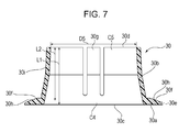
- Fig. 7 is a cross-sectional side view of the throttle member 30 taken along the line VII-VII of Fig. 6 .
- the throttle member 30 is a member that can regulate the flow rate of wash water that passes through the throttle member 30 and that varies depending on the environment in which the water tank 6 is installed so that the flow rate of wash water can be substantially uniform and appropriate for cleaning the bowl body.
- the throttle member 30 is made of a resin material such as a polypropylene, separately from the bowl body 2. As described above, the throttle member 30 can adjust the cross-sectional area of the water-flow passage of the water conduit 23 in accordance with the type of the water tank 6, selected from among the water tanks 6 that supply wash water at different flow rates, so as to reduce the cross-sectional area of the water-flow passage of the water conduit 23 as the flow rate of wash water supplied from the water tank 6 increases.
- the throttle member 30 is removably attached to the small-diameter portion 24e.
- the throttle member 30 while fitted to the small-diameter portion 24e, defines a cylindrical passage having a smaller diameter than the small-diameter portion 24e.
- the throttle member 30 includes an annular base ring portion 30a formed on the upstream side of the throttle member 30 and a pressure-reducing ring portion 30b extending downstream from the base ring portion 30a.
- the base ring portion 30a has a thickness of approximately several millimeters.
- the base ring portion 30a has an outer diameter D2 that is larger than an inner diameter D1 of the small-diameter portion 24e.
- the base ring portion 30a is kept disposed near the small-diameter portion 24e of the bowl body 2 due to hook portions 30g, described below, being capable of being hooked on the small-diameter portion 24e of the bowl body.
- a corrugated gasket 32 seals a connection portion between the outlet 25a and the inlet 24a of the bowl-body water-flow passage 24.
- the base ring portion 30a is not fixed to the outlet 25a and the gasket 32 with an adhesive or the like and is interposed between the outlet 25a and the small-diameter portion 24e.
- the pressure-reducing ring portion 30b defines a cylindrical passage and tapers so that its inner diameter gradually decreases toward the front of the bowl body.
- the pressure-reducing ring portion 30b thus reduces the pressure of a fluid that passes therethrough with an effect of the decrease of the inner diameter.
- the length L2 of the pressure-reducing ring portion 30b is substantially the same as the length L2 of the hook portions 30g, described below.
- the length L2 is approximately 20.5 mm.
- a downstream end 30d of the pressure-reducing ring portion 30b has an inner diameter D5, which is a relatively small diameter and the smallest inner diameter throughout the passage.
- the inner diameter D5 is approximately 31 mm.
- the pressure-reducing ring portion 30b having a longer length or a smaller inner diameter, produces a large pressure loss.
- the pressure-reducing ring portion 30b having a shorter length or a larger inner diameter, produces a small pressure loss.
- the pressure-reducing ring portion 30b can be so shaped as to reduce the cross-sectional area of the water-flow passage of the water conduit 23 in accordance with an increase in flow rate at which water is supplied from the water tank 6 and to increase the cross-sectional area of the water-flow passage of the water conduit 23 in accordance with a reduction in flow rate at which water is supplied from the water tank 6.
- the base ring portion 30a and the pressure-reducing ring portion 30b define, on their inner side, a diameter-reducing passage 31 extending a predetermined length L1 in a direction in which wash water flows.
- the base ring portion 30a defines an upstream end 30c of the diameter-reducing passage 31 whereas the pressure-reducing ring portion 30b defines a downstream end 30d of the diameter-reducing passage 31.
- the cross-sectional area of the water-flow passage of the diameter-reducing passage 31 of the throttle member 30 thus gradually decreases from the upstream end 30c to the downstream end 30d.
- Each protrusion 30f has a taper surface 30h at its top portion.
- the taper surface 20h is inclined inward from the outer side toward the downstream side in the state where the throttle member 30 is fitted to the water conduit 23 (in other words, inclined downward from the inner side to the outer side).
- the taper surface 30h comes into contact with an upstream edge 24f of the small-diameter portion 24e of the bowl body 2.
- the taper surface 30h receives an inward load.
- the throttle member 30 when the throttle member 30 is pressed against the small-diameter portion 24e by the water pressure, the taper surfaces 30h of the multiple protrusions 30f are pressed against the upstream edge 24f of the small-diameter portion 24e and the throttle member 30 receives a force directing toward the axis A1 of the throttle member 30 from the multiple taper surfaces 30h.
- the throttle member 30 can be reliably placed at or shifted to such a position as to allow its axis A1, the axis A2 of the water-supply connecting pipe 25, and the axis A3 of the small-diameter portion 24e to be aligned with one another.
- the pressure-reducing ring portion 30b includes hook-shaped hook portions 30g at two opposing positions on the outer circumference.
- the hook portions 30g protrude outward so as to extend beyond the inner diameter D1 of the small-diameter portion 24e. In the state where the throttle member 30 is fitted to the small-diameter portion 24e, the hook portions 30g can be hooked on a downstream edge 24g of the small-diameter portion 24e.
- these hook portions 30g become apart from the downstream edge 24g of the small-diameter portion 24e while the throttle member 30 is pressed against the small-diameter portion 24e by the water pressure.
- the hook portions 30g can prevent the throttle member 30, fitted to the small-diameter portion 24e, from being detached from or falling out of the small-diameter portion 24e.
- the bowl body 2 can be easily transported while the throttle member 30 is being temporarily or securely fitted to the small-diameter portion 24e.
- the hook portions 30g can prevent the throttle member 30 from unintentionally being detached from or falling out of the small-diameter portion 24e.
- wash water held in the water tank 6 is supplied from the outlet 6a of the water tank 6 through the outlet 25a of the water-supply connecting pipe 25 toward the bowl body 2. Since the water tank 6 is located at a relatively high height, the distance from the water tank 6 to the bowl body 2 (difference of elevation) is relatively long, whereby the wash water is supplied from the outlet 25a at a relatively high flow rate of wash water per unit time.
- the wash water supplied from the outlet 25a flows into the throttle member 30, at which the wash water reduces its flow rate by receiving a gradually increasing pressure loss.
- the water-flow passage at the upstream end 30c of the base ring portion 30a and the water-flow passage at the outlet 25a of the water-supply connecting pipe 25 have substantially the same cross-sectional shape.
- the wash water is less likely to lose its pressure when flowing into the upstream end 30c of the diameter-reducing passage 31.
- the wash water gradually increases the pressure loss and reduces its flow rate in accordance with gradual decrease of the cross-sectional area of the water-flow passage from the upstream end 30c to the downstream end 30d.
- the wash water can reduce its flow rate while continuously flowing in the intended direction without forming turbulence.
- the throttle member 30 facilitates an adjustment of the maximum pressure loss.
- the flow rate of the wash water that flows from the throttle member 30 into the common water-flow passage 24b is thus adjusted to fall within an intended predetermined flow rate range.
- the wash water ejected from the rim outlet 26 after flowing from the common water-flow passage 24b to the rim water-flow passage 24d can be prevented from flowing over a rim portion 18 shaped so as to overhang or extend substantially vertically.
- a swirl flow in the bowl portion 12 can favorably clean the waste receiving surface 16 without flowing over the rim portion 18.
- the wash water ejected from the rim outlet 26 forms a swirl flow in the bowl portion 12 and the swirl flow cleans the waste receiving surface 16 of the bowl portion 12.
- the wash water flows from the common water-flow passage 24b into the jet water-flow passage 24c and is then ejected downward from the jet outlet 28 toward the recessed portion 22 of the bowl portion 12.
- the wash water ejected from the jet outlet 28 forms a vertical swirl flow, whereby waste can be efficiently discharged through the trapway 14.
- the throttle member 30 that can adjust the cross-sectional area of the water-flow passage of the water conduit 23 so as to reduce the cross-sectional area of the water-flow passage of the water conduit 23 as the flow rate of wash water supplied from the water tank 6 increases is fitted to the water conduit 23.
- the flush toilet 1 can supply wash water to the bowl portion 12 at a flow rate appropriate for cleaning the bowl body regardless of whichever water tank 6 that supplies water at any of different flow rates is connected to the bowl body 2.
- the wash water that whirls around the rim portion 18 can be prevented from flowing over the rim portion 18 out of the bowl body.
- this structure can prevent the wash water from failing to fully clean the inside of the bowl portion 12 due to an insufficient force of the wash water whirling around the rim portion 18 caused by an insufficient flow rate of wash water ejected from the rim outlet 26.
- the small-diameter portion 24e has a cross-sectional area C1 of the water-flow passage on the upstream side of the water conduit 23.
- the cross-sectional area C1 of the water-flow passage is smaller than the sum of the cross-sectional area C2 of the water-flow passage of the jet outlet 28 and the cross-sectional area C3 of the water-flow passage of the rim outlet 26.
- the cross-sectional area C1 of the water-flow passage of the small-diameter portion 24e can be changed by changing the throttle member 30.
- the throttle member 30 can adjust the maximum pressure loss received by the wash water passing through the water conduit 23, whereby wash water can be supplied to the bowl portion 12 at a flow rate appropriate for cleaning the bowl body.
- the throttle member 30 tapers so that its cross-sectional area of the water-flow passage gradually decreases from the upstream end to the downstream end, whereby wash water passing through the throttle member 30 can be prevented from forming turbulence and the throttle member 30 facilitates an adjustment of the maximum pressure loss received by the wash water.
- the throttle member 30 since the throttle member 30 has a water-flow passage having a smallest cross-sectional area at the downstream end 30d, the throttle member 30 can adjust the maximum pressure loss received by the wash water passing through the downstream end 30d.
- wash water can be supplied to the bowl portion 12 at a flow rate appropriate for cleaning the bowl body regardless of whichever water tank 6 that supplies water at any of different flow rates is connected to the bowl body 2.
- the flush toilet 1 can regulate the pressure loss received by the wash water that flows into the throttle member 30 from the water-supply connecting pipe 25 extending from the water tank 6, whereby the throttle member 30 facilitates the regulation of the pressure loss.
- wash water can be supplied to the bowl portion 12 at a flow rate appropriate for cleaning the bowl body regardless of whichever water tank 6 that supplies water at any of different flow rates is connected to the bowl body 2.
- the throttle member 30 can be easily fitted to the small-diameter portion 24e of the bowl body 2 that would have dimensional deviation.
- each protrusion has a taper surface 30h on its outer circumferential surface 30e and the taper surface 30h comes into contact with the upstream edge 24f of the small-diameter portion 24e of the bowl body 2.
- the axis A1 of the throttle member 30 can be aligned with the axis A3 of the small-diameter portion 24e when the throttle member 30 is pressed against the small-diameter portion 24e by the water pressure, whereby the center of the throttle member 30 can be reliably aligned.
- the throttle member 30 includes hook portions 30g that are hooked on a downstream side portion of the small-diameter portion 24e. Then, when the bowl body is transported while the throttle member 30 is attached to the bowl body, the throttle member 30 can be prevented from being detached from the bowl body.
- a flush toilet 101 according to a second embodiment of the present invention is described.
- the flush toilet 101 according to the embodiment is different from the flush toilet 1 according to the first embodiment in view of the water tank and the throttle member.
- the following describes only the points that are different between the first embodiment and the second embodiment of the present invention. Similar portions are denoted by the same reference symbols in the drawings and are not described.
- a so-called high-position water tank 6 is connected to the bowl body 2 and the throttle member 30 is attached to the water conduit 23.
- a so-called intermediate-position water tank 106 is connected to the bowl body 102 and the throttle member 130 is attached to the water conduit 123.
- Fig. 8 is a schematic view of a flush toilet 101 according to a second embodiment of the present invention including an intermediate-position water tank 106 installed behind a wall surface.
- Fig. 9 is an enlarged cross-sectional view of a portion B of a water conduit 123 of the flush toilet 101 according to the second embodiment of the present invention.
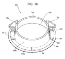
- Fig. 10 is a perspective view of a throttle member 130 of the flush toilet 101 according to the second embodiment of the present invention, viewed obliquely from above.
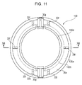
- Fig. 11 is a plan view of the throttle member 130 of the flush toilet 101 according to the second embodiment of the present invention.
- Fig. 12 is a cross-sectional side view of the throttle member taken along the line XII-XII of Fig. 11 .
- the flush toilet 101 includes a bowl body 102, which is installed on a wall 4. Behind the wall 4, a water tank (a so-called intermediate-position water tank) 106 that holds wash water is installed at a height that is lower than the height at which a so-called high-position water tank is installed but higher than the height at which a so-called low-position water tank is installed (for example, installed at a height at which the overall height is approximately 980 mm from the floor).
- a water tank a so-called intermediate-position water tank
- 106 that holds wash water is installed at a height that is lower than the height at which a so-called high-position water tank is installed but higher than the height at which a so-called low-position water tank is installed (for example, installed at a height at which the overall height is approximately 980 mm from the floor).
- the flow rate per unit time at which water is supplied to the bowl body 102 is lower than the flow rate at which water is supplied from the high-position water tank but higher than the flow rate at which water is supplied from the low-position water tank. This is because the vertical distance by which water flows from the intermediate-position water tank 106 to the bowl body 102 (difference of elevation) is at the intermediate level, that is, shorter than the vertical distance by which water flows from the high-position water tank to the bowl body 102 but longer than the vertical distance by which water flows from the low-position water tank to the bowl body 102.
- the flush toilet 1 includes a water conduit 123 including a water-supply connecting pipe 125, extending from an outlet 106a of the water tank 106 to an inlet 24a of the bowl body 102, and extending to the inside of the bowl body 2.
- the water conduit 123 includes a bowl-body water-flow passage 24 extending to a rear portion of the inside of the bowl body 102.
- the water-supply connecting pipe 125 includes an upstream water-supply connecting pipe 125b, extending vertically downward from the outlet 106a of the water tank 106, and a downstream water-supply connecting pipe 125d, extending from an outlet 125c of the upstream water-supply connecting pipe 125b to the inlet 24a of the inside of the bowl body 102.
- the length of the upstream water-supply connecting pipe 125b of the flush toilet 101 according to the second embodiment is shorter than the length of the upstream water-supply connecting pipe 25b of the flush toilet 1 according to the first embodiment.
- the vertical distance by which water flows from the water tank 106 to the bowl body 102 is shorter than the vertical distance by which water flows from the water tank 6 to the bowl body 2 according to the first embodiment.
- Fig. 9 to Fig. 12 the following describes the structure of the flush toilet 101 according to the second embodiment of the present invention in which the throttle member 130 is fitted to the water conduit 123 when the intermediate-position water tank 106 is connected to the bowl body 102.
- the following only describes the points that are different between the first embodiment and the second embodiment.
- the throttle member 130 is a member that can regulate the flow rate of wash water that varies depending on the environment in which the water tank 6 is installed so that the flow rate of wash water can be substantially uniform, appropriate for cleaning the bowl body.
- the throttle member 130 includes an annular base ring portion 30a formed on the upstream side of the throttle member 130 and a pressure-reducing ring portion 130b extending downstream from the base ring portion 30a.
- the pressure-reducing ring portion 130b defines a cylindrical passage and tapers so that its inner diameter gradually decreases toward the front of the bowl.
- the pressure-reducing ring portion 130b thus reduces the pressure of a fluid that passes therethrough.
- the length L3 of the pressure-reducing ring portion 130b is shorter than the length L2 of the hook portions 30g.
- the length L3 is approximately 10 mm.
- a downstream end 130d of the pressure-reducing ring portion 130b according to the second embodiment of the present invention has an inner diameter D6, which is a relatively intermediate diameter larger than the inner diameter D5 of the downstream end 30d according to the first embodiment of the present invention.
- the inner diameter D6 is approximately 34 mm.
- the cross-sectional area C4 of the water-flow passage at the upstream end 30c of the base ring portion 30a is larger than the cross-sectional area C7 of the water-flow passage at the downstream end 130d of the pressure-reducing ring portion 130b and is larger than the cross-sectional area C5 of the water-flow passage at the downstream end 30d of the pressure-reducing ring portion 30b of the throttle member 30 according to the first embodiment of the present invention.
- the pressure loss received by a fluid passing through the pressure-reducing ring portion 130b of the throttle member 130 according to the second embodiment of the present invention is smaller than the pressure loss received by a fluid passing through the pressure-reducing ring portion 30b of the throttle member 30 according to the first embodiment of the present invention.
- wash water held in the water tank 106 is supplied from the outlet 106a of the water tank 106 through the outlet 125a of the water-supply connecting pipe 125 toward the bowl body 102. Since the water tank 106 is located at a height lower than the height at which a so-called high-position water tank 6 is located, the vertical distance by which water flows from the water tank 106 to the bowl body 102 (difference of elevation) is smaller than the vertical distance by which water flows from a high-position water tank to the bowl body, whereby the wash water is supplied from the outlet 125a at a flow rate per unit time smaller than the rate of water supplied from the high-position water tank. The wash water supplied from the outlet 125a flows into the throttle member 130, at which the wash water reduces its pressure and reduces its flow rate.
- the wash water After the wash water flows into the diameter-reducing passage 131, the wash water gradually reduces its flow rate by receiving a gradually increasing pressure loss in accordance with gradual decrease of the cross-sectional area of the water-flow passage from the upstream end to the downstream end.
- the diameter-reducing passage 131 of the throttle member 130 according to the second embodiment of the present invention is shorter than the diameter-reducing passage 31 of the throttle member 30 according to the first embodiment of the present invention.
- the cross-sectional area C7 of the water-flow passage at the downstream end 130d of the pressure-reducing ring portion 130b of the throttle member 130 is larger than the cross-sectional area C5 of the water-flow passage at the downstream end 30d of the pressure-reducing ring portion 30b of the throttle member 30 according to the first embodiment of the present invention.
- the flow rate at which the wash water is supplied into the common water-flow passage 24b from the throttle member 130 is adjusted from a relatively low flow rate originally designed for an intermediate-position water tank 106 to a predetermined flow rate appropriate for cleaning the bowl body that is the same as the flow rate appropriate for cleaning the flush toilet 1 according to the first embodiment of the present invention.
- the wash water ejected from the rim outlet 26 after flowing from the common water-flow passage 24b to the rim water-flow passage 24d can be prevented from flowing over a rim portion 18 shaped so as to overhang or extend substantially vertically.
- the swirl flow in the bowl portion 12 can favorably clean the waste receiving surface 16 without flowing over the rim portion 18.
- the throttle member 130 which can adjust the cross-sectional area of the water-flow passage in such a manner that the water conduit 123 has a smaller cross-sectional area of the water-flow passage as the flow rate of wash water supplied from the water tank 106 increases, is attached to the water conduit 23.
- wash water can be supplied to the bowl portion 12 at a flow rate appropriate for cleaning the bowl body even when an intermediate-position water tank 106 that supplies water at a flow rate that is lower than the flow rate at which water is supplied from a high-position water tank 6 is connected to the bowl body 102 with the presence of the throttle member 130 that can reduce the cross-sectional area of the water-flow passage in the water conduit 123 so as to cope with the intermediate-position water tank 106.
- the wash water that whirls around the rim portion 18 can be prevented from flowing over the rim portion 18 out of the bowl body.
- the wash water can be prevented from failing to fully clean the inside of the bowl portion 12 due to an insufficient force of the wash water whirling around the rim portion 18 caused by an insufficient flow rate of wash water ejected from the rim outlet 26.
- a flush toilet 201 according to a third embodiment of the present invention is described.
- the flush toilet 201 according to the embodiment is different from the flush toilet 1 according to the first embodiment in view of the water tank and the throttle member.
- the following describes only the points that are different between the first embodiment and the third embodiment of the present invention. Similar portions are denoted by the same reference symbols in the drawings and are not described.
- the high-position water tank 6 is connected to the bowl body 2 and the throttle member 30 is attached to the water conduit 23.
- a so-called low-position water tank 206 is connected to the bowl body 202 and the throttle member 30 is removed from a bowl-body water-flow passage 224.
- Fig. 13 is a schematic view of a flush toilet 201 according to a third embodiment of the present invention including a low-position water tank installed behind a wall surface.
- the flush toilet 201 includes a bowl body 202, which is installed on the wall 4. Behind the wall 4, a water tank (a so-called low-position water tank) 206 is installed at a relatively low height (for example, at which the overall height is approximately 820 mm from the floor).
- a water tank a so-called low-position water tank
- the flow rate per unit time at which water is supplied to the bowl body 202 is further lower than the flow rate at which water is supplied from the high-position water tank or the intermediate-position water tank. This is because the vertical distance by which water flows from the low-position water tank 206 to the bowl body 202 (difference of elevation) is at a relatively low level, that is, smaller than the vertical distance by which water flows from the intermediate-position water tank to the bowl body.
- the flow rate at which water is supplied from the water tank 206 is relatively low. If the throttle member 30 remains attached to the bowl body 202, the flow rate of wash water that has passed through the throttle member 30 would fall below the flow rate required for cleaning the bowl. As described above, the low-position water tank 206 is located at a height at which, if the throttle member 30 remains attached to the bowl body 202, the flow rate at which water is supplied from the low-position water tank 206 would fall below a predetermined flow rate of wash water at which the water can fully clean the bowl body.
- the flush toilet 201 includes a water conduit 223 including a water-supply connecting pipe 225, extending from an outlet 206a of the water tank 206 to an inlet 24a of the bowl body 202, and extending to the inside of the bowl body 202.
- the water conduit 223 includes a bowl-body water-flow passage 24 extending to a rear portion of the inside of the bowl body 202.
- the water-supply connecting pipe 225 includes an upstream water-supply connecting pipe 225b, extending vertically downward from the outlet 206a of the water tank 206, and a downstream water-supply connecting pipe 225d, extending from an outlet 225c of the upstream water-supply connecting pipe 225b to the inlet 24a of the inside of the bowl body 202.
- the length of the upstream water-supply connecting pipe 225b of the flush toilet 201 according to the third embodiment is shorter than the length of the upstream water-supply connecting pipe 125b of the flush toilet 101 according to the second embodiment.
- the vertical distance by which water flows from the water tank 206 to the bowl body 202 is shorter than the vertical distance by which water flows from the water tank 106 to the bowl body 102 according to the second embodiment.
- Fig. 13 the following describes the structure of the flush toilet 201 according to the third embodiment of the present invention in which the throttle member 30 is removed from the water conduit 223 when the low-position water tank 206 is connected to the bowl body 202.
- the following only describes the points that are different between the first embodiment and the third embodiment.
- the throttle member 30 is removed from the water conduit 223.
- the inlet 24a of the bowl body 202 is connected to the outlet 25a of the water-supply connecting pipe 25.
- the small-diameter portion 24e forms a water conduit 231 at the inlet 24a of the bowl-body water-flow passage 24.
- the inner diameter D1 ( ⁇ 45 ⁇ 2) of the small-diameter portion 24e is substantially the same as the inner diameter D4 ( ⁇ 41) at the outlet 225a of the water-supply connecting pipe 225.
- wash water does not lose its pressure when flowing into the small-diameter portion 24e from the outlet 225a of the water-supply connecting pipe 225.
- the pressure loss of a fluid passing through the small-diameter portion 24e of the flush toilet 201 according to the third embodiment of the present invention is smaller than the pressure loss of a fluid passing through the pressure-reducing ring portion 130b of the throttle member 130 according to the second embodiment of the present invention.
- wash water held in the water tank 206 is supplied from the outlet 206a of the water tank 206 through the outlet 225a of the water-supply connecting pipe 225 toward the bowl body 202. Since the water tank 206 is located at a relatively low height, the vertical distance by which water flows from the water tank 206 to the bowl body 202 (difference of elevation) is relatively small, whereby the wash water is supplied from the outlet 225a at a flow rate per unit time that is smaller than the flow rate at which water is supplied from the intermediate-position water tank. The wash water supplied from the outlet 225a flows directly into the small-diameter portion 24e.
- the flow rate of the wash water that flows from the small-diameter portion 24e into the common water-flow passage 24b is adjusted from a relatively low flow rate to a predetermined flow rate appropriate for cleaning the bowl body that is the same as the flow rate appropriate for cleaning the flush toilet 1 according to the first embodiment of the present invention.
- the removal of the throttle member 30 thus can reduce the pressure loss of water caused in the water conduit 223.
- the swirl flow in the bowl portion 12 can favorably clean the waste receiving surface 16 without flowing over the rim portion 18.
- the flush toilet 201 according to the third embodiment of the present invention having the above-described structure can exclude a throttle member by removing the throttle member from the water conduit 223 when the flow rate at which water is supplied from the water tank 206 is smaller than a predetermined rate, the throttle member being capable of adjusting the cross-sectional area of the water-flow passage of the water conduit 223 so as to reduce the cross-sectional area of the water-flow passage of the water conduit 223 as the flow rate at which water is supplied from the water tank 206 increases.
- the flush toilet 201 can supply wash water to the bowl portion 12 at a flow rate appropriate for cleaning the bowl body even when a low-position water tank 206 that supplies water at a relatively low flow rate is connected to the bowl body 202.
- the bowl body including the bowl portion 12 including a rim portion 18 having an inner circumferential surface shaped so as to overhang or extend substantially vertically can prevent the wash water from failing to fully clean the inside of the bowl portion 12 due to an insufficient force of the wash water whirling around the rim portion 18 caused by an insufficient flow rate of wash water ejected from the rim outlet 26.
Landscapes
- Health & Medical Sciences (AREA)
- Public Health (AREA)
- Life Sciences & Earth Sciences (AREA)
- Engineering & Computer Science (AREA)
- Hydrology & Water Resources (AREA)
- Water Supply & Treatment (AREA)
- Epidemiology (AREA)
- Sanitary Device For Flush Toilet (AREA)
Abstract
Description
- The present invention relates to flush toilets, and more specifically, it relates to a wash-down flush toilet that cleans a bowl body and discharges waste using wash water supplied from a wash-water supply source.
- Known examples of a flush toilet that cleans itself and discharges waste include a toilet described in
PTL 1 that includes a bowl portion including a rim portion formed at the upper edge of the bowl portion and the rim portion has an inner circumferential surface shaped so as to overhang or extend substantially vertically. In the toilet, wash water held in a water tank is ejected in the horizontal direction from a rim outlet to form a swirl flow for facilitating cleaning. - Besides water tanks directly installed on a toilet bowl, water tanks installed on a wall distant from a toilet bowl are known. Such water tanks are classified into three types depending on the height at which the water tanks are installed: a low-position type, an intermediate-position type, and a high-position type. An appropriate type of water tank is selected from these types in accordance with the installation site and connected to the toilet bowl. Since these three types of water tanks are installed at different heights, the distance of elevation between each water tank and the toilet bowl differs between the water tanks and thus the flow rate at which the water tank supplies water to the toilet bowl also differs between the water tanks.
- [PTL 1] Japanese Unexamined Patent Application Publication No.
2013-44178 - However, using any of such three types of water tanks that supply water at different flow rates in the flush toilet described in
PTL 1 would bring about the following problems. If a high-position water tank, which supplies water at a relatively high flow rate, is used, wash water that whirls around a rim portion having an inner circumferential surface shaped so as to overhang or extend substantially vertically would flow over the rim portion out of the bowl body. Particularly, wash water that whirls around the rim portion is more likely to overflow at areas of the rim portion having small radii of curvature, which are front and rear areas, and at a transition area from the front to a side. - To prevent the wash water from overflowing out of the bowl body to which the high-position water tank is connected, the design of a water conduit of the bowl body may be changed so as to increase the pressure loss and reduce the flow rate at which water is supplied. In this case, the wash water can be prevented from overflowing from the rim portion of the bowl body to which the high-position water tank is connected. If, on the other hand, a low-position water tank, which supplies water at a low flow rate, is connected to the bowl body, the flow rate of wash water that whirls around the rim portion would be insufficient to fully clean the bowl portion of the bowl body.
- One conceivable example to solve these problems is to prepare three types of toilet bowls including water-flow passages differently designed so as to be compatible with the three types of water tanks. Separately preparing three types of toilet bowls, however, increases the number of types of products and increases costs, which is contrary to the recent demand.
- The present invention is made to solve the above-described existing problems and aims to provide a flush toilet that can supply wash water to a bowl portion of a bowl body at a flow rate appropriate for cleaning the bowl body regardless of whichever water tank that supplies water at any of different flow rates is connected to the bowl body.
- In order to achieve the above-described object, the present invention provides a flush toilet that cleans the toilet and discharges waste. The flush toilet includes a water tank that holds wash water and a bowl body. The bowl body includes a bowl portion, a drain, a rim water-ejecting portion, and a water conduit. The bowl portion includes a bowl-shaped waste receiving surface and a rim portion formed at an upper edge of the waste receiving surface and having an inner circumferential surface shaped so as to overhang or extend substantially vertically. The drain has an inlet connected to a lower portion of the bowl portion and allows waste to be discharged therethrough. The rim water-ejecting portion is formed in the inner circumferential surface of the rim portion and forms a swirl flow by ejecting wash water. The water conduit guides the wash water held in the water tank to the rim water-ejecting portion. A throttle member is attached to the water conduit. The throttle member is capable of adjusting a cross-sectional area of a water-flow passage of the water conduit so that the cross-sectional area decreases as the wash water is supplied from the water tank at a higher flow rate.
- In the flush toilet according to the present invention having the above-described structure, the throttle member is attached to the water conduit, and the throttle member can adjust the cross-sectional area of the water-flow passage of the water conduit so as to reduce the cross-sectional area of the water-flow passage of the water conduit as the flow rate of wash water supplied from the water tank increases. Thus, the flush toilet can supply wash water to the bowl portion at a flow rate appropriate for cleaning the bowl portion regardless of whichever water tank that supplies water at any of different flow rates is connected to the bowl body. Even when the flow rate of wash water ejected from the rim outlet increases in the bowl body that includes the bowl portion including the rim portion having an inner circumferential surface shaped so as to overhang or extend substantially vertically, the wash water that whirls around the rim portion can be prevented from flowing over the rim portion out of the bowl body. In addition, this structure can prevent the wash water from failing to fully clean the inside of the bowl portion due to an insufficient force of the wash water whirling around the rim portion caused by an insufficient flow rate of wash water ejected from the rim outlet.
- Preferably, in this invention, the bowl body includes a jet ejection portion that ejects the wash water from a jet outlet of the jet ejection portion that is open at a side portion of the waste receiving surface of the bowl portion, and the water conduit is split so as to extend to the jet ejection portion of the bowl body. The water conduit has a small-diameter portion at an upstream-side portion of the water conduit. The small-diameter portion has a water-flow passage having a cross-sectional area smaller than the sum of a cross-sectional area of the jet outlet of the jet ejection portion and a cross-sectional area of an outlet of the rim water-ejecting portion. The throttle member is removably attached to the small-diameter portion, and the cross-sectional area of the water-flow passage of the small-diameter portion is changeable by replacing the throttle member with another throttle member.
- In the flush toilet according to the present invention having the above-described structure, the small-diameter portion has a water-flow passage having a cross-sectional area on the upstream side of the water conduit. The cross-sectional area of the water-flow passage is smaller than the sum of the cross-sectional area of the jet outlet and the cross-sectional area of the rim outlet. The cross-sectional area of the water-flow passage of the small-diameter portion can be changed by replacing the throttle member with another throttle member. Thus, the throttle member can adjust the maximum pressure loss received by the wash water passing through the water conduit, whereby the wash water can be supplied to the bowl portion at a flow rate appropriate for cleaning the bowl portion regardless of whichever water tank that supplies water at any of different flow rates is connected to the bowl body.
- Preferably, in this embodiment, the water conduit has a small-diameter portion at an upstream-side portion of the water conduit, and the small-diameter portion has a water-flow passage having a cross-sectional area smaller than the sum of cross-sectional areas of outlets of the rim water-ejecting portion. The throttle member is removably attached to the small-diameter portion, and the cross-sectional area of the water-flow passage of the small-diameter portion is changeable by replacing the throttle member with another throttle member.
- In the flush toilet according to the present invention having the above-described structure, the small-diameter portion disposed at an upstream-side portion of the water conduit has a water-flow passage having a cross-sectional area smaller than the sum of cross-sectional areas of outlets of the rim water-ejecting portion. Thus, replacing the throttle member with another one enables a change of the cross-sectional area of the water-flow passage of the small-diameter portion, so that the throttle member can adjust the maximum pressure loss received by the wash water passing through the water conduit. Thus, wash water can be supplied to the bowl portion at a flow rate appropriate for cleaning the bowl portion regardless of whichever water tank that supplies water at any of different flow rates is connected to the bowl body.
- Preferably, in this invention, the throttle member forms a passage extending a predetermined length in a direction in which wash water flows, and the throttle member tapers so that a cross-sectional area of a water-flow passage of the throttle member gradually decreases from an upstream end to a downstream end.
- In the flush toilet according to the present invention having the above-described structure, the throttle member tapers so that its cross-sectional area of the water-flow passage gradually decreases from the upstream end to the downstream end, whereby wash water passing through the throttle member can be prevented from forming turbulence and the throttle member facilitates an adjustment of the maximum pressure loss that the wash water receives. In addition, since the throttle member has a water-flow passage having a smallest cross-sectional area at the downstream end, the throttle member can adjust the maximum pressure loss received by the wash water passing through the downstream end. Thus, wash water can be supplied to the bowl portion at a flow rate appropriate for cleaning the bowl portion regardless of whichever water tank that supplies water at any of different flow rates is connected to the bowl body.
- Preferably, in this invention, the cross-sectional area of the water-flow passage of the throttle member at the upstream end is substantially the same as a cross-sectional area of a water-flow passage of a water-supply connecting pipe connected to an upstream-side portion of the throttle member, a cross-sectional shape of the water-flow passage of the throttle member at the upstream end is substantially the same as a cross-sectional shape of the water-flow passage of the water-supply connecting pipe, and an axis of the throttle member and an axis of the water-supply connecting pipe at a connection portion are substantially aligned with each other.
- The flush toilet according to the present invention having the above-described structure can regulate the pressure loss received by the wash water that flows into the throttle member from the water-supply connecting pipe, whereby the throttle member facilitates the regulation of the pressure loss. Thus, wash water can be supplied to the bowl portion at a flow rate appropriate for cleaning the bowl portion regardless of whichever water tank that supplies water at any of different flow rates is connected to the bowl body.
- Preferably, in this invention, in the state where the throttle member is attached to the small-diameter portion of the bowl body, a gap having a predetermined dimension is left between an outer circumferential surface of the throttle member facing outward and an inner circumferential surface of the small-diameter portion of the bowl body facing inward.
- In the flush toilet according to the present invention having the above-described structure, the throttle member can be easily attached to the small-diameter portion of the bowl body that would have dimensional deviation.
- Preferably, in this invention, the throttle member includes a plurality of protrusions disposed on an outer circumferential surface at predetermined intervals on a circumference of the outer circumferential surface, each of the protrusions has, at a top portion, a taper surface that is inclined downward from an inner side to an outer side, and the taper surface comes into contact with the small-diameter portion of the bowl body.
- In the flush toilet according to the present invention having the above-described structure, each protrusion has a taper surface on the outer circumferential surface of the throttle member and the taper surface comes into contact with the small-diameter portion of the bowl body. Thus, the axis of the throttle member can be aligned with the axis of the small-diameter portion when the throttle member is pressed against the small-diameter portion by the water pressure, whereby the center of the throttle member can be reliably aligned.
- Preferably, in this invention, the throttle member includes a hook portion hooked on a downstream-side portion of the small-diameter portion.
- In the flush toilet according to the present invention having the above-described structure, the throttle member includes a hook portion hooked on a downstream side portion of the small-diameter portion. Thus, when the bowl body is transported while the throttle member is attached to the bowl body, the throttle member can be prevented from being detached from the bowl body.
- Preferably, in this invention, a flush toilet that cleans the toilet and discharges waste includes a water tank that holds wash water and a bowl body. The bowl body includes a bowl portion, a drain, a rim water-ejecting portion, and a water conduit. The bowl portion includes a bowl-shaped waste receiving surface and a rim portion formed at an upper edge of the waste receiving surface and having an inner circumferential surface shaped so as to overhang or extend substantially vertically. The drain has an inlet connected to a lower portion of the bowl portion and allows waste to be discharged therethrough. The rim water-ejecting portion is formed in the inner circumferential surface of the rim portion and forms a swirl flow by ejecting wash water. The water conduit guides the wash water held in the water tank to the rim water-ejecting portion. A throttle member is attached to the water conduit. The throttle member is capable of adjusting a cross-sectional area of a water-flow passage of the water conduit so that the cross-sectional area decreases as the wash water is supplied from the water tank at a higher flow rate. The throttle member is a member different from the bowl body and removable from the bowl body. The throttle member is removed when the flow rate of the wash water supplied from the water tank is smaller than a predetermined flow rate.
- The flush toilet according to the present invention having the above-described structure can exclude a throttle member by removing the throttle member from the water conduit when the flow rate at which water is supplied from the water tank is smaller than a predetermined rate, the throttle member being capable of adjusting the cross-sectional area of the water-flow passage of the water conduit so as to reduce the cross-sectional area of the water-flow passage of the water conduit as the flow rate at which water is supplied from the water tank increases. Thus, the flush toilet can supply wash water to the bowl portion at a flow rate appropriate for cleaning the bowl portion even when a water tank that supplies water at a relatively low flow rate is connected to the bowl body. Thus, the bowl body including the bowl portion including a rim portion having an inner circumferential surface shaped so as to overhang or extend substantially vertically can prevent the wash water from failing to fully clean the inside of the bowl portion due to an insufficient force of the wash water whirling around the rim portion caused by an insufficient flow rate of the wash water ejected from the rim outlet.
- The flush toilet according to the present invention having the above-described structure can supply wash water to a bowl portion of a bowl body at a flow rate appropriate for cleaning the bowl portion regardless of whichever water tank that supplies water at any of different flow rates is connected to the bowl body.
-
- [
Fig. 1] Fig. 1 is a schematic diagram of a flush toilet according to a first embodiment of the present invention including a high-position water tank and installed on a wall surface. - [
Fig. 2] Fig. 2 is a plan view of the flush toilet according to the first embodiment of the present invention. - [
Fig. 3] Fig. 3 is a cross-sectional side view of a portion of the flush toilet taken along the line III-III ofFig. 2 . - [
Fig. 4] Fig. 4 is an enlarged cross-sectional view of a portion B of a water conduit of the flush toilet according to the first embodiment of the present invention illustrated inFig. 1 . - [
Fig. 5] Fig. 5 is a perspective view of a throttle member of the flush toilet according to the first embodiment of the present invention, viewed obliquely from above. - [
Fig. 6] Fig. 6 is a plan view of the throttle member of the flush toilet according to the first embodiment of the present invention. - [
Fig. 7] Fig. 7 is a cross-sectional side view of the throttle member taken along the line VII-VII ofFig. 6 . - [
Fig. 8] Fig. 8 is a schematic view of a flush toilet according to a second embodiment of the present invention including an intermediate-position water tank installed behind a wall surface. - [
Fig. 9] Fig. 9 is an enlarged cross-sectional view of a portion B of a water conduit of the flush toilet according to the second embodiment of the present invention illustrated inFig. 8 . - [
Fig. 10] Fig. 10 is a perspective view of a throttle member of the flush toilet according to the second embodiment of the present invention, viewed obliquely from above. - [
Fig. 11] Fig. 11 is a plan view of the throttle member of the flush toilet according to the second embodiment of the present invention. - [
Fig. 12] Fig. 12 is a cross-sectional side view of the throttle member taken along the line XII-XII ofFig. 11 . - [
Fig. 13] Fig. 13 is a schematic view of a flush toilet according to a third embodiment of the present invention including a low-position water tank installed behind a wall surface. - Referring now to the appended drawings, flush toilets according to some embodiments of the present invention will be described. Referring to
Fig. 1 first, an installation of a flush toilet according to an embodiment is described.Fig. 1 is a schematic diagram of aflush toilet 1 according to a first embodiment of the present invention including a high-position water tank and installed on a wall surface. As illustrated inFig. 1 , theflush toilet 1 is a wash-down flush toilet (wash-down toilet) that discharges waste using a difference of elevation due to rising of the water level of water accumulated in a trapway, described below. In this embodiment, the flush toilet may be another type of a toilet, such as a siphon toilet. - The
flush toilet 1 includes aceramic bowl body 2, which is installed on awall 4. Behind thewall 4, a water tank (a so-called high-position water tank) 6 that holds wash water is installed at a relatively high height (for example, at which the overall height is approximately 1120 mm from the floor). Thewater tank 6 is connected to a wash-water supply source (not illustrated) such as a water supply line. To the surface of thewall 4, anoperation switch 8 is attached. When theoperation switch 8 is turned on, wash water held in thewater tank 6 is supplied to thebowl body 2 to clean thebowl body 2. - Behind the
wall 4, adrainpipe 10 for discharging waste is installed. Thedrainpipe 10 allows waste to be discharged from thebowl body 2 to the outside. - Although the
water tank 6 of theflush toilet 1 according to the first embodiment of the present invention is a water tank concealed behind thewall 4, the water tank may be installed in front of the wall. - The
flush toilet 1 according to the first embodiment of the present invention includes a high-position water tank as thewater tank 6. Another water tank is also selectable, in accordance with the height at which the water tank is installed, from among, for example, three different types of water tanks: a high-position water tank installed at a relatively high height at which the overall height of the water tank is approximately 1120 mm from the floor; a low-position water tank installed at a relatively low height at which the overall height of the water tank is approximately 820 mm from the floor; and an intermediate-position water tank installed at an intermediate height between the relatively high height and the relatively low height at which the overall height of the water tank is approximately 980 mm from the floor. Such a water tank may be installed in combination with a new bowl body, a water tank already installed at the site may be used in combination with a newly installed bowl body, or a water tank may be replaced with a new one after a bowl body has been installed. - Referring now to
Fig. 2 andFig. 3 , theflush toilet 1 according to the embodiment is described in detail.Fig. 2 is a plan view of theflush toilet 1 according to the first embodiment of the present invention.Fig. 3 is a cross-sectional side view of a portion of theflush toilet 1 taken along the line III-III ofFig. 2 . - As illustrated in
Fig. 2 andFig. 3 , thebowl body 2 of theflush toilet 1 according to the embodiment of the present invention includes abowl portion 12 and atrapway 14 extending continuously with a bottom portion of thebowl portion 12. Thebowl portion 12 includes awaste receiving surface 16 and arim portion 18 at an upper edge of thewaste receiving surface 16. Therim portion 18 has an inner circumferential surface shaped so as to overhang or extend substantially vertically. Therim portion 18 is shaped so as to overhang or extend substantially vertically and smoothly upright continuously with the upper edge of thewaste receiving surface 16. Thewaste receiving surface 16 of thebowl portion 12 includes a bowl-shaped upper waste-receivingsurface 20 and a recessedportion 22 formed between the upper waste-receivingsurface 20 and thetrapway 14. - The
trapway 14 extends obliquely upward from aninlet 14a that is open in the bottom portion of thebowl portion 12, bends at theuppermost point 14b, and extends obliquely downward until arriving at anoutlet 14c, at which thetrapway 14 is connected to the above-described drainpipe 10 (seeFig. 1 ). The water level L of water accumulated in theflush toilet 1 is flush with theuppermost point 14b of thetrapway 14. - In addition, the
flush toilet 1 includes awater conduit 23 including a water-supply connecting pipe 25 that extends from anoutlet 6a of thewater tank 6 to aninlet 24a of thebowl body 2. Theflush toilet 1 extends to the inside of thebowl body 2. Thewater conduit 23 also includes a bowl-body water-flow passage 24 extending to a rear portion of the inside of thebowl body 2. The water-supply connecting pipe 25 includes an upstream water-supply connecting pipe 25b, extending vertically downward from theoutlet 6a of thewater tank 6, and a downstream water-supply connecting pipe 25d, extending from anoutlet 25c of the upstream water-supply connecting pipe 25b to theinlet 24a of the inside of thebowl body 2. - The bowl-body water-
flow passage 24 includes a common water-flow passage 24b, a jet water-flow passage 24c, and a rim water-flow passage 24d. The common water-flow passage 24b extends from theinlet 24a of the bowl-body water-flow passage 24, connected to theoutlet 25a of the water-supply connecting pipe 25 extending from thewater tank 6, to the vicinity of a rear portion of thebowl portion 12. The jet water-flow passage 24c branches off from the common water-flow passage 24b at the vicinity of a rear portion of thebowl portion 12. The common water-flow passage 24b receives wash water from thewater tank 6. - A
rim outlet 26 is formed at a front left portion on the inner circumferential side of therim portion 18 when thebowl body 2 is viewed from the front. The above-described rim water-flow passage 24d extends to therim outlet 26, to which wash water is supplied. From therim outlet 26, wash water is ejected forward and forms a swirl flow inside thebowl portion 12. - As illustrated in
Fig. 2 andFig. 3 , ajet outlet 28 is formed at a substantially middle portion on the left side (a side) of thewaste receiving surface 16 of thebowl portion 12 when thebowl portion 12 is viewed from the front. Thejet outlet 28 is formed above the water surface W0. Thejet outlet 28 is connected with the jet water-flow passage 24c branching off from the common water-flow passage 24b of the bowl-body water-flow passage 24. A mainstream of wash water ejected from thejet outlet 28 flows into the water (water surface W0) accumulated in the recessedportion 22 and then whirls. - A small-
diameter portion 24e at which the diameter of a water-flow passage is reduced is formed at theinlet 24a of the bowl-body water-flow passage 24. The small-diameter portion 24e defines a circular opening and allows acylindrical throttle member 30 to be fitted to the inner circumferential side of the small-diameter portion 24e. The cross-sectional area C1 of a water flow (cross-sectional area of a water-flow passage) of the small-diameter portion 24e is determined so as to be larger than the cross-sectional area of the water-flow passage of the water-supply connecting pipe 25 but smallest throughout the cross-sectional area of the water-flow passage of the bowl-body water-flow passage 24. When thethrottle member 30 is fitted to the small-diameter portion 24e, the small-diameter portion 24e has a water-flow passage having a smallest cross-sectional area throughout the water-supply connecting pipe 25 and the bowl-body water-flow passage 24. The cross-sectional area C1 of the water-flow passage of the small-diameter portion 24e is smaller than the sum of the cross-sectional area C2 of the water-flow passage of thejet outlet 28 and the cross-sectional area C3 of the water-flow passage of therim outlet 26. Thus, the cross-sectional area C1 of the water-flow passage of the small-diameter portion 24e determines, or the cross-sectional area C5 of the water-flow passage of thedownstream end 30d of thethrottle member 30 when inserted into the small-diameter portion 24e, determines the flow rate of wash water flowing through the bowl-body water-flow passage 24. When thethrottle member 30 is not fitted to the small-diameter portion 24e, the small-diameter portion 24e forms a water-flow passage at theinlet 24a of the bowl-body water-flow passage 24. - In the case of a bowl body that only includes a rim outlet or outlets and a rim water-flow passage without a jet outlet and a jet water-flow passage, the cross-sectional area of the water-flow passage of the small-diameter portion is determined to be smaller than the cross-sectional area of the water-flow passage of the rim outlet or the sum of the cross-sectional areas of the water-flow passages of the rim outlets. For example, in the case of a bowl body only including one rim outlet and a rim water-flow passage, the cross-sectional area of the water-flow passage of the small-diameter portion is determined to be smaller than the cross-sectional area of the water-flow passage of the rim outlet. In the case of a bowl body including two rim outlets and a rim water-flow passage, the cross-sectional area of the water-flow passage of the small-
diameter portion 24e is determined to be smaller than the sum of the cross-sectional areas of the water-flow passages of the two rim outlets. - Referring now to
Fig. 4 to Fig. 7 , thethrottle member 30 attached to thewater conduit 23 when the high-position water tank 6 is connected to thebowl body 2 is described in detail. -
Fig. 4 is an enlarged cross-sectional view of an inlet B of the bowl-body water-flow passage 24 of theflush toilet 1 according to the first embodiment of the present invention illustrated inFig. 1 .Fig. 5 is a perspective view of athrottle member 30 of theflush toilet 1 according to the first embodiment of the present invention, viewed obliquely from above.Fig. 6 is a plan view of thethrottle member 30 of theflush toilet 1 according to the first embodiment of the present invention.Fig. 7 is a cross-sectional side view of thethrottle member 30 taken along the line VII-VII ofFig. 6 . - The
throttle member 30 is a member that can regulate the flow rate of wash water that passes through thethrottle member 30 and that varies depending on the environment in which thewater tank 6 is installed so that the flow rate of wash water can be substantially uniform and appropriate for cleaning the bowl body. - The
throttle member 30 is made of a resin material such as a polypropylene, separately from thebowl body 2. As described above, thethrottle member 30 can adjust the cross-sectional area of the water-flow passage of thewater conduit 23 in accordance with the type of thewater tank 6, selected from among thewater tanks 6 that supply wash water at different flow rates, so as to reduce the cross-sectional area of the water-flow passage of thewater conduit 23 as the flow rate of wash water supplied from thewater tank 6 increases. Thethrottle member 30 is removably attached to the small-diameter portion 24e. By replacing thethrottle member 30 with another throttle member having a different shape or by removing thethrottle member 30, the cross-sectional area of a water-flow passage of a portion near the small-diameter portion 24e can be easily changed. When theflush toilet 1 is shipped from the factory, thethrottle member 30 is fitted into the small-diameter portion 24e. Thethrottle member 30 may be replaced with athrottle member 130 included in aflush toilet 101 according to a second embodiment of the present invention, which will be described below. Alternatively, thethrottle member 30 may be removed from the small-diameter portion 24e to form aflush toilet 201 according to a third embodiment of the present invention. - The
throttle member 30, while fitted to the small-diameter portion 24e, defines a cylindrical passage having a smaller diameter than the small-diameter portion 24e. Thethrottle member 30 includes an annularbase ring portion 30a formed on the upstream side of thethrottle member 30 and a pressure-reducingring portion 30b extending downstream from thebase ring portion 30a. - The
base ring portion 30a has a thickness of approximately several millimeters. Thebase ring portion 30a has an outer diameter D2 that is larger than an inner diameter D1 of the small-diameter portion 24e. Thebase ring portion 30a is kept disposed near the small-diameter portion 24e of thebowl body 2 due tohook portions 30g, described below, being capable of being hooked on the small-diameter portion 24e of the bowl body. Acorrugated gasket 32 seals a connection portion between theoutlet 25a and theinlet 24a of the bowl-body water-flow passage 24. Thebase ring portion 30a is not fixed to theoutlet 25a and thegasket 32 with an adhesive or the like and is interposed between theoutlet 25a and the small-diameter portion 24e. - The pressure-reducing
ring portion 30b defines a cylindrical passage and tapers so that its inner diameter gradually decreases toward the front of the bowl body. The pressure-reducingring portion 30b thus reduces the pressure of a fluid that passes therethrough with an effect of the decrease of the inner diameter. The length L2 of the pressure-reducingring portion 30b is substantially the same as the length L2 of thehook portions 30g, described below. For example, the length L2 is approximately 20.5 mm. Adownstream end 30d of the pressure-reducingring portion 30b has an inner diameter D5, which is a relatively small diameter and the smallest inner diameter throughout the passage. For example, the inner diameter D5 is approximately 31 mm. - The pressure-reducing
ring portion 30b, having a longer length or a smaller inner diameter, produces a large pressure loss. On the other hand, the pressure-reducingring portion 30b, having a shorter length or a larger inner diameter, produces a small pressure loss. In this manner, the pressure-reducingring portion 30b can be so shaped as to reduce the cross-sectional area of the water-flow passage of thewater conduit 23 in accordance with an increase in flow rate at which water is supplied from thewater tank 6 and to increase the cross-sectional area of the water-flow passage of thewater conduit 23 in accordance with a reduction in flow rate at which water is supplied from thewater tank 6. - The
base ring portion 30a and the pressure-reducingring portion 30b define, on their inner side, a diameter-reducingpassage 31 extending a predetermined length L1 in a direction in which wash water flows. Thebase ring portion 30a defines anupstream end 30c of the diameter-reducingpassage 31 whereas the pressure-reducingring portion 30b defines adownstream end 30d of the diameter-reducingpassage 31. The cross-sectional area of the water-flow passage of the diameter-reducingpassage 31 of thethrottle member 30 thus gradually decreases from theupstream end 30c to thedownstream end 30d.Fig. 4 shows that the cross-sectional area C4 of the water-flow passage at theupstream end 30c of thebase ring portion 30a is larger than the cross-sectional area C5 of the water-flow passage at thedownstream end 30d of the pressure-reducingring portion 30b. - The cross-sectional area C4 of the water-flow passage at the
upstream end 30c of thebase ring portion 30a is substantially the same as the cross-sectional area C6 of the water-flow passage at theoutlet 25a of the water-supply connecting pipe 25 that is connected to an upstream end portion of thethrottle member 3. The water-flow passage at theupstream end 30c of thebase ring portion 30a and the water-flow passage at theoutlet 25a of the water-supply connecting pipe 25 have substantially the same cross-sectional shape, that is, a substantially circular cross section. An axis A1 of thethrottle member 30 and an axis A2 of the water-supply connecting pipe 25 are substantially aligned with each other. - The inner diameter D1 of the small-
diameter portion 24e is larger than the outer diameter D3 of the pressure-reducingring portion 30b of thethrottle member 30. Thus, in the state where thethrottle member 30 is fitted to the small-diameter portion 24e of thebowl body 2, a gap G having a predetermined dimension is formed between an outercircumferential surface 30i of the pressure-reducingring portion 30b facing outward and an innercircumferential surface 24h of the small-diameter portion 24e of thebowl body 2 facing inward. The gap G can accommodate dimensional variation of the small-diameter portion 24e of thebowl body 2 when thethrottle member 30 is fitted to the small-diameter portion 24e. -
Multiple protrusions 30f are disposed on an outercircumferential surface 30e of thebase ring portion 30a, facing downward, at predetermined intervals on the circumference of the outercircumferential surface 30e. In this embodiment, theseprotrusions 30f disposed on the outercircumferential surface 30e are arranged so as to be symmetrically with respect to the center of the circle on, when viewed in a plan, both sides of each of twohook portions 30g, described below, and at positions on a line perpendicular to the line connecting the twohook portions 30g. However, theprotrusions 30f on the outercircumferential surface 30e may be arranged at other predetermined intervals, for example, at predetermined equal intervals. - Each
protrusion 30f has ataper surface 30h at its top portion. The taper surface 20h is inclined inward from the outer side toward the downstream side in the state where thethrottle member 30 is fitted to the water conduit 23 (in other words, inclined downward from the inner side to the outer side). Thetaper surface 30h comes into contact with anupstream edge 24f of the small-diameter portion 24e of thebowl body 2. When coming into contact with theupstream edge 24f, thetaper surface 30h receives an inward load. - Thus, when the
throttle member 30 is pressed against the small-diameter portion 24e by the water pressure, the taper surfaces 30h of themultiple protrusions 30f are pressed against theupstream edge 24f of the small-diameter portion 24e and thethrottle member 30 receives a force directing toward the axis A1 of thethrottle member 30 from themultiple taper surfaces 30h. Thus, thethrottle member 30 can be reliably placed at or shifted to such a position as to allow its axis A1, the axis A2 of the water-supply connecting pipe 25, and the axis A3 of the small-diameter portion 24e to be aligned with one another. - The pressure-reducing
ring portion 30b includes hook-shapedhook portions 30g at two opposing positions on the outer circumference. Thehook portions 30g protrude outward so as to extend beyond the inner diameter D1 of the small-diameter portion 24e. In the state where thethrottle member 30 is fitted to the small-diameter portion 24e, thehook portions 30g can be hooked on adownstream edge 24g of the small-diameter portion 24e. - As illustrated in
Fig. 4 , thesehook portions 30g become apart from thedownstream edge 24g of the small-diameter portion 24e while thethrottle member 30 is pressed against the small-diameter portion 24e by the water pressure. In the case where thebowl body 2 is transported, thehook portions 30g can prevent thethrottle member 30, fitted to the small-diameter portion 24e, from being detached from or falling out of the small-diameter portion 24e. For example, during shipment, transportation, installation of theflush toilet 1, thebowl body 2 can be easily transported while thethrottle member 30 is being temporarily or securely fitted to the small-diameter portion 24e. Even when thebowl body 2 is not transported, thehook portions 30g can prevent thethrottle member 30 from unintentionally being detached from or falling out of the small-diameter portion 24e. - Referring mainly to
Fig. 1 to Fig. 4 , the operation of theflush toilet 1 according to the embodiment of the present invention is described. - When a user turns the
operation switch 8 on, wash water held in thewater tank 6 is supplied from theoutlet 6a of thewater tank 6 through theoutlet 25a of the water-supply connecting pipe 25 toward thebowl body 2. Since thewater tank 6 is located at a relatively high height, the distance from thewater tank 6 to the bowl body 2 (difference of elevation) is relatively long, whereby the wash water is supplied from theoutlet 25a at a relatively high flow rate of wash water per unit time. The wash water supplied from theoutlet 25a flows into thethrottle member 30, at which the wash water reduces its flow rate by receiving a gradually increasing pressure loss. - More specifically, the water-flow passage at the
upstream end 30c of thebase ring portion 30a and the water-flow passage at theoutlet 25a of the water-supply connecting pipe 25 have substantially the same cross-sectional shape. Thus, the wash water is less likely to lose its pressure when flowing into theupstream end 30c of the diameter-reducingpassage 31. After the wash water flows into the diameter-reducingpassage 31, the wash water gradually increases the pressure loss and reduces its flow rate in accordance with gradual decrease of the cross-sectional area of the water-flow passage from theupstream end 30c to thedownstream end 30d. Since the cross-sectional area of the water-flow passage of the diameter-reducingpassage 31 of thethrottle member 30 gradually decreases from theupstream end 30c to thedownstream end 30d, the wash water can reduce its flow rate while continuously flowing in the intended direction without forming turbulence. Thus, thethrottle member 30 facilitates an adjustment of the maximum pressure loss. - The flow rate of the wash water that flows from the
throttle member 30 into the common water-flow passage 24b is thus adjusted to fall within an intended predetermined flow rate range. Thus, the wash water ejected from therim outlet 26 after flowing from the common water-flow passage 24b to the rim water-flow passage 24d can be prevented from flowing over arim portion 18 shaped so as to overhang or extend substantially vertically. - When the wash water is ejected to the
bowl portion 12 from therim outlet 26 at a flow rate appropriate for cleaning the bowl body, a swirl flow in thebowl portion 12 can favorably clean thewaste receiving surface 16 without flowing over therim portion 18. - The wash water ejected from the
rim outlet 26 forms a swirl flow in thebowl portion 12 and the swirl flow cleans thewaste receiving surface 16 of thebowl portion 12. At the same time, the wash water flows from the common water-flow passage 24b into the jet water-flow passage 24c and is then ejected downward from thejet outlet 28 toward the recessedportion 22 of thebowl portion 12. The wash water ejected from thejet outlet 28 forms a vertical swirl flow, whereby waste can be efficiently discharged through thetrapway 14. - Hereinbelow, an operation of the
flush toilet 1 according to the first embodiment of the present invention is specifically described. In theflush toilet 1 according to the embodiment, thethrottle member 30 that can adjust the cross-sectional area of the water-flow passage of thewater conduit 23 so as to reduce the cross-sectional area of the water-flow passage of thewater conduit 23 as the flow rate of wash water supplied from thewater tank 6 increases is fitted to thewater conduit 23. Thus, theflush toilet 1 can supply wash water to thebowl portion 12 at a flow rate appropriate for cleaning the bowl body regardless of whicheverwater tank 6 that supplies water at any of different flow rates is connected to thebowl body 2. Even when the flow rate of wash water ejected from therim outlet 26 increases in the bowl body that includes thebowl portion 12 including therim portion 18 having an inner circumferential surface shaped so as to overhang or extend substantially vertically, the wash water that whirls around therim portion 18 can be prevented from flowing over therim portion 18 out of the bowl body. In addition, this structure can prevent the wash water from failing to fully clean the inside of thebowl portion 12 due to an insufficient force of the wash water whirling around therim portion 18 caused by an insufficient flow rate of wash water ejected from therim outlet 26. - In the
flush toilet 1 according to the embodiment, the small-diameter portion 24e has a cross-sectional area C1 of the water-flow passage on the upstream side of thewater conduit 23. The cross-sectional area C1 of the water-flow passage is smaller than the sum of the cross-sectional area C2 of the water-flow passage of thejet outlet 28 and the cross-sectional area C3 of the water-flow passage of therim outlet 26. The cross-sectional area C1 of the water-flow passage of the small-diameter portion 24e can be changed by changing thethrottle member 30. Thus, thethrottle member 30 can adjust the maximum pressure loss received by the wash water passing through thewater conduit 23, whereby wash water can be supplied to thebowl portion 12 at a flow rate appropriate for cleaning the bowl body. - In the
flush toilet 1 according to the embodiment, thethrottle member 30 tapers so that its cross-sectional area of the water-flow passage gradually decreases from the upstream end to the downstream end, whereby wash water passing through thethrottle member 30 can be prevented from forming turbulence and thethrottle member 30 facilitates an adjustment of the maximum pressure loss received by the wash water. In addition, since thethrottle member 30 has a water-flow passage having a smallest cross-sectional area at thedownstream end 30d, thethrottle member 30 can adjust the maximum pressure loss received by the wash water passing through thedownstream end 30d. Thus, wash water can be supplied to thebowl portion 12 at a flow rate appropriate for cleaning the bowl body regardless of whicheverwater tank 6 that supplies water at any of different flow rates is connected to thebowl body 2. - The
flush toilet 1 according to the embodiment can regulate the pressure loss received by the wash water that flows into thethrottle member 30 from the water-supply connecting pipe 25 extending from thewater tank 6, whereby thethrottle member 30 facilitates the regulation of the pressure loss. Thus, wash water can be supplied to thebowl portion 12 at a flow rate appropriate for cleaning the bowl body regardless of whicheverwater tank 6 that supplies water at any of different flow rates is connected to thebowl body 2. - In the
flush toilet 1 according to the embodiment, thethrottle member 30 can be easily fitted to the small-diameter portion 24e of thebowl body 2 that would have dimensional deviation. - In the
flush toilet 1 according to the embodiment, each protrusion has ataper surface 30h on its outercircumferential surface 30e and thetaper surface 30h comes into contact with theupstream edge 24f of the small-diameter portion 24e of thebowl body 2. Thus, the axis A1 of thethrottle member 30 can be aligned with the axis A3 of the small-diameter portion 24e when thethrottle member 30 is pressed against the small-diameter portion 24e by the water pressure, whereby the center of thethrottle member 30 can be reliably aligned. - In the
flush toilet 1 according to the embodiment, thethrottle member 30 includeshook portions 30g that are hooked on a downstream side portion of the small-diameter portion 24e. Then, when the bowl body is transported while thethrottle member 30 is attached to the bowl body, thethrottle member 30 can be prevented from being detached from the bowl body. - Referring now to
Fig. 8 to Fig. 12 , aflush toilet 101 according to a second embodiment of the present invention is described. Theflush toilet 101 according to the embodiment is different from theflush toilet 1 according to the first embodiment in view of the water tank and the throttle member. The following describes only the points that are different between the first embodiment and the second embodiment of the present invention. Similar portions are denoted by the same reference symbols in the drawings and are not described. In the first embodiment described above, a so-called high-position water tank 6 is connected to thebowl body 2 and thethrottle member 30 is attached to thewater conduit 23. In the second embodiment, on the other hand, a so-called intermediate-position water tank 106 is connected to thebowl body 102 and thethrottle member 130 is attached to thewater conduit 123. -
Fig. 8 is a schematic view of aflush toilet 101 according to a second embodiment of the present invention including an intermediate-position water tank 106 installed behind a wall surface.Fig. 9 is an enlarged cross-sectional view of a portion B of awater conduit 123 of theflush toilet 101 according to the second embodiment of the present invention.Fig. 10 is a perspective view of athrottle member 130 of theflush toilet 101 according to the second embodiment of the present invention, viewed obliquely from above.Fig. 11 is a plan view of thethrottle member 130 of theflush toilet 101 according to the second embodiment of the present invention.Fig. 12 is a cross-sectional side view of the throttle member taken along the line XII-XII ofFig. 11 . - As illustrated in
Fig. 8 andFig. 9 , theflush toilet 101 includes abowl body 102, which is installed on awall 4. Behind thewall 4, a water tank (a so-called intermediate-position water tank) 106 that holds wash water is installed at a height that is lower than the height at which a so-called high-position water tank is installed but higher than the height at which a so-called low-position water tank is installed (for example, installed at a height at which the overall height is approximately 980 mm from the floor). - When the intermediate-
position water tank 106 is connected to thebowl body 102, the flow rate per unit time at which water is supplied to thebowl body 102 is lower than the flow rate at which water is supplied from the high-position water tank but higher than the flow rate at which water is supplied from the low-position water tank. This is because the vertical distance by which water flows from the intermediate-position water tank 106 to the bowl body 102 (difference of elevation) is at the intermediate level, that is, shorter than the vertical distance by which water flows from the high-position water tank to thebowl body 102 but longer than the vertical distance by which water flows from the low-position water tank to thebowl body 102. - In addition, the
flush toilet 1 includes awater conduit 123 including a water-supply connecting pipe 125, extending from anoutlet 106a of thewater tank 106 to aninlet 24a of thebowl body 102, and extending to the inside of thebowl body 2. Thewater conduit 123 includes a bowl-body water-flow passage 24 extending to a rear portion of the inside of thebowl body 102. The water-supply connecting pipe 125 includes an upstream water-supply connecting pipe 125b, extending vertically downward from theoutlet 106a of thewater tank 106, and a downstream water-supply connecting pipe 125d, extending from anoutlet 125c of the upstream water-supply connecting pipe 125b to theinlet 24a of the inside of thebowl body 102. The length of the upstream water-supply connecting pipe 125b of theflush toilet 101 according to the second embodiment is shorter than the length of the upstream water-supply connecting pipe 25b of theflush toilet 1 according to the first embodiment. Thus, the vertical distance by which water flows from thewater tank 106 to thebowl body 102 is shorter than the vertical distance by which water flows from thewater tank 6 to thebowl body 2 according to the first embodiment. - Referring now to
Fig. 9 to Fig. 12 , the following describes the structure of theflush toilet 101 according to the second embodiment of the present invention in which thethrottle member 130 is fitted to thewater conduit 123 when the intermediate-position water tank 106 is connected to thebowl body 102. The following only describes the points that are different between the first embodiment and the second embodiment. - The
throttle member 130 is a member that can regulate the flow rate of wash water that varies depending on the environment in which thewater tank 6 is installed so that the flow rate of wash water can be substantially uniform, appropriate for cleaning the bowl body. Thethrottle member 130 includes an annularbase ring portion 30a formed on the upstream side of thethrottle member 130 and a pressure-reducingring portion 130b extending downstream from thebase ring portion 30a. - The pressure-reducing
ring portion 130b defines a cylindrical passage and tapers so that its inner diameter gradually decreases toward the front of the bowl. The pressure-reducingring portion 130b thus reduces the pressure of a fluid that passes therethrough. The length L3 of the pressure-reducingring portion 130b is shorter than the length L2 of thehook portions 30g. For example, the length L3 is approximately 10 mm. Adownstream end 130d of the pressure-reducingring portion 130b according to the second embodiment of the present invention has an inner diameter D6, which is a relatively intermediate diameter larger than the inner diameter D5 of thedownstream end 30d according to the first embodiment of the present invention. For example, the inner diameter D6 is approximately 34 mm. - The
base ring portion 30a and the pressure-reducingring portion 130b define, on their inner side, a diameter-reducingpassage 131 extending a predetermined length L4 in a direction in which wash water flows. Thebase ring portion 30a defines anupstream end 30c of the diameter-reducingpassage 131 whereas the pressure-reducingring portion 130b defines adownstream end 130d of the diameter-reducingpassage 131. Thus, the diameter-reducingpassage 131 of thethrottle member 130 according to the second embodiment of the present invention is shorter than the diameter-reducingpassage 31 of thethrottle member 30 according to the first embodiment of the present invention. - In
Fig. 9 andFig. 12 , the cross-sectional area C4 of the water-flow passage at theupstream end 30c of thebase ring portion 30a is larger than the cross-sectional area C7 of the water-flow passage at thedownstream end 130d of the pressure-reducingring portion 130b and is larger than the cross-sectional area C5 of the water-flow passage at thedownstream end 30d of the pressure-reducingring portion 30b of thethrottle member 30 according to the first embodiment of the present invention. - Thus, the pressure loss received by a fluid passing through the pressure-reducing
ring portion 130b of thethrottle member 130 according to the second embodiment of the present invention is smaller than the pressure loss received by a fluid passing through the pressure-reducingring portion 30b of thethrottle member 30 according to the first embodiment of the present invention. - Subsequently, an operation of the
flush toilet 101 according to the second embodiment of the present invention is described, but only the points that are different between the first embodiment and the second embodiment. - When a user turns the
operation switch 8 on, wash water held in thewater tank 106 is supplied from theoutlet 106a of thewater tank 106 through theoutlet 125a of the water-supply connecting pipe 125 toward thebowl body 102. Since thewater tank 106 is located at a height lower than the height at which a so-called high-position water tank 6 is located, the vertical distance by which water flows from thewater tank 106 to the bowl body 102 (difference of elevation) is smaller than the vertical distance by which water flows from a high-position water tank to the bowl body, whereby the wash water is supplied from theoutlet 125a at a flow rate per unit time smaller than the rate of water supplied from the high-position water tank. The wash water supplied from theoutlet 125a flows into thethrottle member 130, at which the wash water reduces its pressure and reduces its flow rate. - After the wash water flows into the diameter-reducing
passage 131, the wash water gradually reduces its flow rate by receiving a gradually increasing pressure loss in accordance with gradual decrease of the cross-sectional area of the water-flow passage from the upstream end to the downstream end. The diameter-reducingpassage 131 of thethrottle member 130 according to the second embodiment of the present invention is shorter than the diameter-reducingpassage 31 of thethrottle member 30 according to the first embodiment of the present invention. The cross-sectional area C7 of the water-flow passage at thedownstream end 130d of the pressure-reducingring portion 130b of thethrottle member 130 is larger than the cross-sectional area C5 of the water-flow passage at thedownstream end 30d of the pressure-reducingring portion 30b of thethrottle member 30 according to the first embodiment of the present invention. Thus, the flow rate at which the wash water is supplied into the common water-flow passage 24b from thethrottle member 130 is adjusted from a relatively low flow rate originally designed for an intermediate-position water tank 106 to a predetermined flow rate appropriate for cleaning the bowl body that is the same as the flow rate appropriate for cleaning theflush toilet 1 according to the first embodiment of the present invention. - Thus, the wash water ejected from the
rim outlet 26 after flowing from the common water-flow passage 24b to the rim water-flow passage 24d can be prevented from flowing over arim portion 18 shaped so as to overhang or extend substantially vertically. - When the wash water is ejected to the
bowl portion 12 from therim outlet 26 at a flow rate appropriate for cleaning the bowl body, the swirl flow in thebowl portion 12 can favorably clean thewaste receiving surface 16 without flowing over therim portion 18. - In the
flush toilet 101 according to the second embodiment of the present invention having the above-described structure, thethrottle member 130, which can adjust the cross-sectional area of the water-flow passage in such a manner that thewater conduit 123 has a smaller cross-sectional area of the water-flow passage as the flow rate of wash water supplied from thewater tank 106 increases, is attached to thewater conduit 23. Thus, wash water can be supplied to thebowl portion 12 at a flow rate appropriate for cleaning the bowl body even when an intermediate-position water tank 106 that supplies water at a flow rate that is lower than the flow rate at which water is supplied from a high-position water tank 6 is connected to thebowl body 102 with the presence of thethrottle member 130 that can reduce the cross-sectional area of the water-flow passage in thewater conduit 123 so as to cope with the intermediate-position water tank 106. Even when the flow rate of wash water ejected from therim outlet 26 increases in the bowl body that includes thebowl portion 12 including therim portion 18 having an inner circumferential surface shaped so as to overhang or extend substantially vertically, the wash water that whirls around therim portion 18 can be prevented from flowing over therim portion 18 out of the bowl body. In addition, the wash water can be prevented from failing to fully clean the inside of thebowl portion 12 due to an insufficient force of the wash water whirling around therim portion 18 caused by an insufficient flow rate of wash water ejected from therim outlet 26. - Referring now to
Fig. 13 , aflush toilet 201 according to a third embodiment of the present invention is described. Theflush toilet 201 according to the embodiment is different from theflush toilet 1 according to the first embodiment in view of the water tank and the throttle member. The following describes only the points that are different between the first embodiment and the third embodiment of the present invention. Similar portions are denoted by the same reference symbols in the drawings and are not described. In the first embodiment described above, the high-position water tank 6 is connected to thebowl body 2 and thethrottle member 30 is attached to thewater conduit 23. In the third embodiment, on the other hand, a so-called low-position water tank 206 is connected to thebowl body 202 and thethrottle member 30 is removed from a bowl-body water-flow passage 224. -
Fig. 13 is a schematic view of aflush toilet 201 according to a third embodiment of the present invention including a low-position water tank installed behind a wall surface. - As illustrated in
Fig. 13 , theflush toilet 201 includes abowl body 202, which is installed on thewall 4. Behind thewall 4, a water tank (a so-called low-position water tank) 206 is installed at a relatively low height (for example, at which the overall height is approximately 820 mm from the floor). - When the low-
position water tank 206 is connected to thebowl body 202, the flow rate per unit time at which water is supplied to thebowl body 202 is further lower than the flow rate at which water is supplied from the high-position water tank or the intermediate-position water tank. This is because the vertical distance by which water flows from the low-position water tank 206 to the bowl body 202 (difference of elevation) is at a relatively low level, that is, smaller than the vertical distance by which water flows from the intermediate-position water tank to the bowl body. - When, for example, such a low-
position water tank 206 is connected to thebowl body 202, the flow rate at which water is supplied from thewater tank 206 is relatively low. If thethrottle member 30 remains attached to thebowl body 202, the flow rate of wash water that has passed through thethrottle member 30 would fall below the flow rate required for cleaning the bowl. As described above, the low-position water tank 206 is located at a height at which, if thethrottle member 30 remains attached to thebowl body 202, the flow rate at which water is supplied from the low-position water tank 206 would fall below a predetermined flow rate of wash water at which the water can fully clean the bowl body. - In addition, the
flush toilet 201 includes a water conduit 223 including a water-supply connecting pipe 225, extending from anoutlet 206a of thewater tank 206 to aninlet 24a of thebowl body 202, and extending to the inside of thebowl body 202. The water conduit 223 includes a bowl-body water-flow passage 24 extending to a rear portion of the inside of thebowl body 202. The water-supply connecting pipe 225 includes an upstream water-supply connecting pipe 225b, extending vertically downward from theoutlet 206a of thewater tank 206, and a downstream water-supply connecting pipe 225d, extending from anoutlet 225c of the upstream water-supply connecting pipe 225b to theinlet 24a of the inside of thebowl body 202. The length of the upstream water-supply connecting pipe 225b of theflush toilet 201 according to the third embodiment is shorter than the length of the upstream water-supply connecting pipe 125b of theflush toilet 101 according to the second embodiment. Thus, the vertical distance by which water flows from thewater tank 206 to thebowl body 202 is shorter than the vertical distance by which water flows from thewater tank 106 to thebowl body 102 according to the second embodiment. - Referring now to
Fig. 13 , the following describes the structure of theflush toilet 201 according to the third embodiment of the present invention in which thethrottle member 30 is removed from the water conduit 223 when the low-position water tank 206 is connected to thebowl body 202. The following only describes the points that are different between the first embodiment and the third embodiment. - As illustrated in
Fig. 13 , in theflush toilet 201 according to the third embodiment of the present invention, thethrottle member 30 is removed from the water conduit 223. Theinlet 24a of thebowl body 202 is connected to theoutlet 25a of the water-supply connecting pipe 25. In the above-described state where thethrottle member 30 is not attached to thebowl body 202, the small-diameter portion 24e forms awater conduit 231 at theinlet 24a of the bowl-body water-flow passage 24. - The inner diameter D1 (φ45 ± 2) of the small-
diameter portion 24e is substantially the same as the inner diameter D4 (φ41) at theoutlet 225a of the water-supply connecting pipe 225. Thus, wash water does not lose its pressure when flowing into the small-diameter portion 24e from theoutlet 225a of the water-supply connecting pipe 225. - Thus, the pressure loss of a fluid passing through the small-
diameter portion 24e of theflush toilet 201 according to the third embodiment of the present invention is smaller than the pressure loss of a fluid passing through the pressure-reducingring portion 130b of thethrottle member 130 according to the second embodiment of the present invention. - Subsequently, an operation of the
flush toilet 201 according to the third embodiment of the present invention is described, but only the points that are different between the first embodiment and the third embodiment. - When a user turns the
operation switch 8 on, wash water held in thewater tank 206 is supplied from theoutlet 206a of thewater tank 206 through theoutlet 225a of the water-supply connecting pipe 225 toward thebowl body 202. Since thewater tank 206 is located at a relatively low height, the vertical distance by which water flows from thewater tank 206 to the bowl body 202 (difference of elevation) is relatively small, whereby the wash water is supplied from theoutlet 225a at a flow rate per unit time that is smaller than the flow rate at which water is supplied from the intermediate-position water tank. The wash water supplied from theoutlet 225a flows directly into the small-diameter portion 24e. Thus, the flow rate of the wash water that flows from the small-diameter portion 24e into the common water-flow passage 24b is adjusted from a relatively low flow rate to a predetermined flow rate appropriate for cleaning the bowl body that is the same as the flow rate appropriate for cleaning theflush toilet 1 according to the first embodiment of the present invention. The removal of thethrottle member 30 thus can reduce the pressure loss of water caused in the water conduit 223. - This structure can prevent wash water ejected from the
rim outlet 26 after flowing from the common water-flow passage 24b to the rim water-flow passage 24d from failing to favorably clean thewaste receiving surface 16 due to an insufficient flow rate of wash water. - Since the wash water is ejected from the
rim outlet 26 to thebowl portion 12 at a flow rate appropriate for cleaning the bowl body, the swirl flow in thebowl portion 12 can favorably clean thewaste receiving surface 16 without flowing over therim portion 18. - The
flush toilet 201 according to the third embodiment of the present invention having the above-described structure can exclude a throttle member by removing the throttle member from the water conduit 223 when the flow rate at which water is supplied from thewater tank 206 is smaller than a predetermined rate, the throttle member being capable of adjusting the cross-sectional area of the water-flow passage of the water conduit 223 so as to reduce the cross-sectional area of the water-flow passage of the water conduit 223 as the flow rate at which water is supplied from thewater tank 206 increases. Thus, theflush toilet 201 can supply wash water to thebowl portion 12 at a flow rate appropriate for cleaning the bowl body even when a low-position water tank 206 that supplies water at a relatively low flow rate is connected to thebowl body 202. Thus, the bowl body including thebowl portion 12 including arim portion 18 having an inner circumferential surface shaped so as to overhang or extend substantially vertically can prevent the wash water from failing to fully clean the inside of thebowl portion 12 due to an insufficient force of the wash water whirling around therim portion 18 caused by an insufficient flow rate of wash water ejected from therim outlet 26. -
- 1, 101, 201:
- flush toilet
- 2, 102, 202:
- bowl body
- 6, 106, 206:
- water tank
- 6b:
- outlet
- 12:
- bowl portion
- 14:
- trapway
- 16:
- waste receiving surface
- 18:
- rim portion
- 23:
- water conduit
- 24:
- bowl-body water-flow passage
- 24a:
- inlet
- 24b:
- common water-flow passage
- 24c:
- jet water-flow passage
- 24d:
- rim water-flow passage
- 24e:
- small-diameter portion
- 25, 125, 225:
- water-supply connecting pipe
- 26:
- rim outlet
- 28:
- jet outlet
- 30, 130:
- throttle member
- 30a:
- base ring portion
- 30b, 130b:
- pressure-reducing ring portion
- 30c:
- upstream end
- 30d:
- downstream end
- 30e:
- outer circumferential surface
- 30f:
- protrusion
- 30g:
- hook portion
- 30h:
- taper surface
- 30i:
- downstream-faced outer circumferential surface
- G:
- gap
- L:
- water level
- W0:
- water surface
Claims (9)
- A flush toilet that cleans the toilet and discharges waste, comprising:a water tank that holds wash water; anda bowl body that includes a bowl portion, a drain, a rim water-ejecting portion, and a water conduit, the bowl portion including a bowl-shaped waste receiving surface and a rim portion formed at an upper edge of the waste receiving surface and having an inner circumferential surface shaped so as to overhang or extend substantially vertically, the drain having an inlet connected to a lower portion of the bowl portion and allowing waste to be discharged therethrough, the rim water-ejecting portion being formed in the inner circumferential surface of the rim portion and forming a swirl flow by ejecting wash water, and the water conduit guiding the wash water held in the water tank to the rim water-ejecting portion,wherein a throttle member is attached to the water conduit, the throttle member is capable of adjusting a cross-sectional area of a water-flow passage of the water conduit so that the cross-sectional area decreases as the wash water is supplied from the water tank at a higher flow rate, and the throttle member is a member different from the bowl body.
- The flush toilet according to Claim 1,
wherein the bowl body includes a jet ejection portion that ejects the wash water from a jet outlet of the jet ejection portion that is open at a side portion of the waste receiving surface of the bowl portion, and the water conduit is split so as to extend to the jet ejection portion of the bowl body,
wherein the water conduit has a small-diameter portion at an upstream-side portion of the water conduit, the small-diameter portion having a cross-sectional area of a water-flow passage smaller than the sum of a cross-sectional area of the jet outlet of the jet ejection portion and a cross-sectional area of an outlet of the rim water-ejecting portion, and
wherein the throttle member is removably attached to the small-diameter portion, and the cross-sectional area of the water-flow passage of the small-diameter portion is changeable by replacing the throttle member with another throttle member. - The flush toilet according to Claim 1,
wherein the water conduit has a small-diameter portion at an upstream-side portion of the water conduit, the small-diameter portion having a cross-sectional area of the water-flow passage smaller than the sum of cross-sectional areas of outlets of the rim water-ejecting portion, and
wherein the throttle member is removably attached to the small-diameter portion, and the cross-sectional area of the water-flow passage of the small-diameter portion is changeable by replacing the throttle member with another throttle member. - The flush toilet according to Claim 2 or 3, wherein the throttle member forms a passage extending a predetermined length in a direction in which wash water flows, and the throttle member tapers so that a cross-sectional area of a water-flow passage of the throttle member gradually decreases from an upstream end to a downstream end.
- The flush toilet according to any one of Claims 2 to 4, wherein the cross-sectional area of the water-flow passage of the throttle member at the upstream end is substantially the same as a cross-sectional area of a water-flow passage of a water-supply connecting pipe connected to an upstream-side portion of the throttle member, a cross-sectional shape of the water-flow passage of the throttle member at the upstream end is substantially the same as a cross-sectional shape of the water-flow passage of the water-supply connecting pipe, and an axis of the throttle member and an axis of the water-supply connecting pipe at a connection portion are substantially aligned with each other.
- The flush toilet according to any one of Claims 2 to 5, wherein, in the state where the throttle member is attached to the small-diameter portion of the bowl body, a gap having a predetermined dimension is left between an outer circumferential surface of the throttle member facing outward and an inner circumferential surface of the small-diameter portion of the bowl body facing inward.
- The flush toilet according to Claim 6, wherein the throttle member includes a plurality of protrusions disposed on an outer circumferential surface at predetermined intervals on a circumference of the outer circumferential surface, each of the protrusions has, at a top portion, a taper surface that is inclined downward from an inner side to an outer side, and the taper surface comes into contact with the small-diameter portion of the bowl body.
- The flush toilet according to any one of Claims 2 to 7, wherein the throttle member includes a hook portion hooked on a downstream-side portion of the small-diameter portion.
- A flush toilet that cleans the toilet and discharges waste, comprising:a water tank that holds wash water; anda bowl body that includes a bowl portion, a drain, a rim water-ejecting portion, and a water conduit, the bowl portion including a bowl-shaped waste receiving surface and a rim portion formed at an upper edge of the waste receiving surface and having an inner circumferential surface shaped so as to overhang or extend substantially vertically, the drain having an inlet connected to a lower portion of the bowl portion and allowing waste to be discharged therethrough, the rim water-ejecting portion being formed in the inner circumferential surface of the rim portion and forming a swirl flow by ejecting wash water, and the water conduit guiding the wash water held in the water tank to the rim water-ejecting portion,wherein a throttle member is attached to the water conduit, the throttle member is capable of adjusting a cross-sectional area of a water-flow passage of the water conduit so that the cross-sectional area decreases as the wash water is supplied from the water tank at a higher flow rate, and the throttle member is a member different from the bowl body and removable from the bowl body, andwherein the throttle member is removed when the flow rate of the wash water supplied from the water tank is smaller than a predetermined flow rate.
Applications Claiming Priority (1)
| Application Number | Priority Date | Filing Date | Title |
|---|---|---|---|
| JP2013256798A JP6428993B2 (en) | 2013-12-12 | 2013-12-12 | Flush toilet |
Publications (1)
| Publication Number | Publication Date |
|---|---|
| EP2884014A1 true EP2884014A1 (en) | 2015-06-17 |
Family
ID=52021045
Family Applications (1)
| Application Number | Title | Priority Date | Filing Date |
|---|---|---|---|
| EP14196965.9A Withdrawn EP2884014A1 (en) | 2013-12-12 | 2014-12-09 | Toilet with throttle to limit the flow rate of flushing water |
Country Status (3)
| Country | Link |
|---|---|
| EP (1) | EP2884014A1 (en) |
| JP (1) | JP6428993B2 (en) |
| CN (1) | CN104712042B (en) |
Cited By (3)
| Publication number | Priority date | Publication date | Assignee | Title |
|---|---|---|---|---|
| EP3453804A1 (en) * | 2017-09-12 | 2019-03-13 | Geberit International AG | Flushing device |
| CN111021497A (en) * | 2019-12-20 | 2020-04-17 | 中山市康丽洁卫浴科技有限公司 | A toilet flush tank that can be quickly assembled to a decorative panel |
| CN112824614A (en) * | 2019-11-21 | 2021-05-21 | 吉博力国际股份公司 | Flushing water dispenser |
Families Citing this family (13)
| Publication number | Priority date | Publication date | Assignee | Title |
|---|---|---|---|---|
| US10053849B2 (en) * | 2016-02-19 | 2018-08-21 | Toto Ltd. | Flush toilet |
| JP6432588B2 (en) * | 2016-12-07 | 2018-12-05 | Toto株式会社 | Flush toilet |
| JP7066969B2 (en) * | 2017-01-12 | 2022-05-16 | Toto株式会社 | Wash-off toilet bowl |
| DK3444408T3 (en) * | 2017-08-18 | 2020-12-21 | Geberit Int Ag | TOILET WITH RINSE WATER CONNECTION |
| JP7336743B2 (en) * | 2019-05-23 | 2023-09-01 | パナソニックIpマネジメント株式会社 | Drainage sockets and their associated drain connections |
| CN210713114U (en) * | 2019-08-13 | 2020-06-09 | 广东太古卫浴科技有限公司 | A wall-mounted toilet |
| JP7344439B2 (en) * | 2019-08-30 | 2023-09-14 | Toto株式会社 | flush toilet |
| JP6970392B2 (en) * | 2020-02-04 | 2021-11-24 | Toto株式会社 | Washing toilet |
| JP7237285B2 (en) * | 2020-08-28 | 2023-03-13 | Toto株式会社 | flush toilet |
| JP7205805B2 (en) * | 2020-08-28 | 2023-01-17 | Toto株式会社 | flush toilet |
| JP7409410B2 (en) * | 2022-02-28 | 2024-01-09 | Toto株式会社 | flush toilet |
| JP2024030001A (en) * | 2022-08-23 | 2024-03-07 | Toto株式会社 | Seal member |
| KR102894824B1 (en) * | 2024-10-28 | 2025-12-03 | (주)우림엔지니어링건축사사무소 | Toilet operation method in apartment complex |
Citations (5)
| Publication number | Priority date | Publication date | Assignee | Title |
|---|---|---|---|---|
| DE2648072A1 (en) * | 1976-10-23 | 1978-04-27 | Schwab Sanitaer Plastic Gmbh | Toilet flushing tube extending between bowl and cistern - has enlarged diameter section and restrictor valve at lower end to reduce noise |
| DE3315926A1 (en) * | 1982-05-10 | 1983-12-08 | VEB Kombinat Technische Gebäudeausrüstung, DDR 7730 Leipzig | Water distributor for WCs |
| US20130047326A1 (en) * | 2011-08-24 | 2013-02-28 | Toto Ltd. | Flush toilet |
| JP2013044178A (en) | 2011-08-24 | 2013-03-04 | Toto Ltd | Flush toilet bowl |
| EP2602391A1 (en) * | 2011-12-05 | 2013-06-12 | KERAMAG Keramische Werke Aktiengesellschaft | Toilet bowl |
Family Cites Families (4)
| Publication number | Priority date | Publication date | Assignee | Title |
|---|---|---|---|---|
| JPS5617587Y2 (en) * | 1977-10-08 | 1981-04-23 | ||
| CN1016630B (en) * | 1988-07-25 | 1992-05-13 | 东陶机器株式会社 | The rinse water supply method and the device of chamber pot |
| JP3823963B2 (en) * | 2003-09-26 | 2006-09-20 | 東陶機器株式会社 | Flush toilet |
| JP6021042B2 (en) * | 2012-03-30 | 2016-11-02 | Toto株式会社 | Flush toilet |
-
2013
- 2013-12-12 JP JP2013256798A patent/JP6428993B2/en active Active
-
2014
- 2014-12-09 EP EP14196965.9A patent/EP2884014A1/en not_active Withdrawn
- 2014-12-10 CN CN201410757007.8A patent/CN104712042B/en active Active
Patent Citations (5)
| Publication number | Priority date | Publication date | Assignee | Title |
|---|---|---|---|---|
| DE2648072A1 (en) * | 1976-10-23 | 1978-04-27 | Schwab Sanitaer Plastic Gmbh | Toilet flushing tube extending between bowl and cistern - has enlarged diameter section and restrictor valve at lower end to reduce noise |
| DE3315926A1 (en) * | 1982-05-10 | 1983-12-08 | VEB Kombinat Technische Gebäudeausrüstung, DDR 7730 Leipzig | Water distributor for WCs |
| US20130047326A1 (en) * | 2011-08-24 | 2013-02-28 | Toto Ltd. | Flush toilet |
| JP2013044178A (en) | 2011-08-24 | 2013-03-04 | Toto Ltd | Flush toilet bowl |
| EP2602391A1 (en) * | 2011-12-05 | 2013-06-12 | KERAMAG Keramische Werke Aktiengesellschaft | Toilet bowl |
Cited By (3)
| Publication number | Priority date | Publication date | Assignee | Title |
|---|---|---|---|---|
| EP3453804A1 (en) * | 2017-09-12 | 2019-03-13 | Geberit International AG | Flushing device |
| CN112824614A (en) * | 2019-11-21 | 2021-05-21 | 吉博力国际股份公司 | Flushing water dispenser |
| CN111021497A (en) * | 2019-12-20 | 2020-04-17 | 中山市康丽洁卫浴科技有限公司 | A toilet flush tank that can be quickly assembled to a decorative panel |
Also Published As
| Publication number | Publication date |
|---|---|
| CN104712042A (en) | 2015-06-17 |
| JP6428993B2 (en) | 2018-11-28 |
| JP2015113633A (en) | 2015-06-22 |
| CN104712042B (en) | 2018-09-11 |
Similar Documents
| Publication | Publication Date | Title |
|---|---|---|
| JP6428993B2 (en) | Flush toilet | |
| JP6472591B2 (en) | Flush toilet | |
| US10704243B2 (en) | Flush toilet | |
| US7661153B2 (en) | Flush toilet | |
| JP5802959B2 (en) | Flush toilet | |
| JP5804242B2 (en) | Flush toilet | |
| CA3074606C (en) | Sanitary facility in the form of a toilet | |
| JP2015113633A5 (en) | ||
| JP6338196B2 (en) | Flush toilet | |
| JP6061065B2 (en) | Flush toilet | |
| JP2015183485A (en) | Water closet | |
| JP6629030B2 (en) | Flush toilet | |
| JP2018105048A (en) | Flush toilet bowl | |
| JP2020026699A (en) | Flush water closet | |
| JP5435408B2 (en) | Wash-away toilet | |
| JP2015183484A (en) | Water closet | |
| JP6727557B2 (en) | Flush toilet | |
| US10738452B2 (en) | Flush toilet | |
| JP2018012995A (en) | Flush toilet bowl | |
| JP2014051883A (en) | Flush water closet | |
| JP2020159188A (en) | Flush toilet | |
| JP2019173324A (en) | Flush toilet bowl | |
| JP7082312B2 (en) | Washing toilet | |
| JP6629029B2 (en) | Flush toilet | |
| JP6716099B2 (en) | Flush toilet |
Legal Events
| Date | Code | Title | Description |
|---|---|---|---|
| PUAI | Public reference made under article 153(3) epc to a published international application that has entered the european phase |
Free format text: ORIGINAL CODE: 0009012 |
|
| 17P | Request for examination filed |
Effective date: 20141209 |
|
| AK | Designated contracting states |
Kind code of ref document: A1 Designated state(s): AL AT BE BG CH CY CZ DE DK EE ES FI FR GB GR HR HU IE IS IT LI LT LU LV MC MK MT NL NO PL PT RO RS SE SI SK SM TR |
|
| AX | Request for extension of the european patent |
Extension state: BA ME |
|
| R17P | Request for examination filed (corrected) |
Effective date: 20151215 |
|
| RBV | Designated contracting states (corrected) |
Designated state(s): AL AT BE BG CH CY CZ DE DK EE ES FI FR GB GR HR HU IE IS IT LI LT LU LV MC MK MT NL NO PL PT RO RS SE SI SK SM TR |
|
| 17Q | First examination report despatched |
Effective date: 20160420 |
|
| STAA | Information on the status of an ep patent application or granted ep patent |
Free format text: STATUS: EXAMINATION IS IN PROGRESS |
|
| STAA | Information on the status of an ep patent application or granted ep patent |
Free format text: STATUS: THE APPLICATION HAS BEEN WITHDRAWN |
|
| 18W | Application withdrawn |
Effective date: 20190607 |