EP2883997A1 - Laundry drying apparatus and method for controlling condenser in laundry drying apparatus - Google Patents
Laundry drying apparatus and method for controlling condenser in laundry drying apparatus Download PDFInfo
- Publication number
- EP2883997A1 EP2883997A1 EP14193589.0A EP14193589A EP2883997A1 EP 2883997 A1 EP2883997 A1 EP 2883997A1 EP 14193589 A EP14193589 A EP 14193589A EP 2883997 A1 EP2883997 A1 EP 2883997A1
- Authority
- EP
- European Patent Office
- Prior art keywords
- water
- water outlet
- condenser
- outlet
- control valve
- Prior art date
- Legal status (The legal status is an assumption and is not a legal conclusion. Google has not performed a legal analysis and makes no representation as to the accuracy of the status listed.)
- Granted
Links
Images

Classifications
-
- D—TEXTILES; PAPER
- D06—TREATMENT OF TEXTILES OR THE LIKE; LAUNDERING; FLEXIBLE MATERIALS NOT OTHERWISE PROVIDED FOR
- D06F—LAUNDERING, DRYING, IRONING, PRESSING OR FOLDING TEXTILE ARTICLES
- D06F58/00—Domestic laundry dryers
- D06F58/20—General details of domestic laundry dryers
- D06F58/24—Condensing arrangements
-
- D—TEXTILES; PAPER
- D06—TREATMENT OF TEXTILES OR THE LIKE; LAUNDERING; FLEXIBLE MATERIALS NOT OTHERWISE PROVIDED FOR
- D06F—LAUNDERING, DRYING, IRONING, PRESSING OR FOLDING TEXTILE ARTICLES
- D06F58/00—Domestic laundry dryers
- D06F58/30—Drying processes
-
- D—TEXTILES; PAPER
- D06—TREATMENT OF TEXTILES OR THE LIKE; LAUNDERING; FLEXIBLE MATERIALS NOT OTHERWISE PROVIDED FOR
- D06F—LAUNDERING, DRYING, IRONING, PRESSING OR FOLDING TEXTILE ARTICLES
- D06F58/00—Domestic laundry dryers
- D06F58/20—General details of domestic laundry dryers
- D06F58/22—Lint collecting arrangements
Definitions
- the present invention relates to the field of home appliances, and more particularly to a laundry drying apparatus and a method for controlling a condenser in a laundry drying apparatus.
- a drying function for laundry applies process air at high temperature to laundry for drying, in order to evaporate and remove humidity from the laundry. Humidity thus evaporated and removed as vapor may then be condensed by use of a condenser which reduces the temperature of the process air and vapor contained therein, and transforms the vapor back to humidity.
- a condenser is usually a water-cooled condenser or an air-cooled condenser.
- the present invention relates to a water-cooled condenser, which is referred to as a condenser in short hereinafter.
- the control of a condenser mainly includes a cooling function for condensing vapor, and a washing function for cleaning the condenser from fluff which is a fine particular matter extracted from the laundry being dried by the process air and retained in the condenser by means of the condensed humidity.
- a cooling function for condensing vapor mainly includes a cooling function for condensing vapor, and a washing function for cleaning the condenser from fluff which is a fine particular matter extracted from the laundry being dried by the process air and retained in the condenser by means of the condensed humidity.
- a relatively small water flow is mainly fed to the condenser. With the water consumption thus required, a more stable water flow achieves a better cooling effect.
- washing is to clean impurities and sediments as fluff and possibly also residuals from washing liquids in the condenser, a relatively large water flow needs to be fed to the condenser.
- two different water control valves are used to implement a cooling function and a washing function for a condenser.
- a water control valve allowing a water flow of 0.5 l/min (liter/minute) or 0.25 l/min is used, and switching timing of that water control valve is controlled to achieve a water flow required;
- a water control valve allowing 10 l/min or 8 l/min is used to wash the condenser.
- a water control valve having a small flow rate for implementing a cooling function may have problems of relatively low precision of a flow rate allowance. Further, easy formation of sediments in a high temperature working environment might further affect precision.
- the present invention provides a laundry drying apparatus and a method for controlling a condenser in a laundry drying apparatus, so as to implement a cooling function and a washing function for a condenser by using one water control valve.
- a selection between a cooling function and a cleaning function is enabled by providing a water tank between the water inlet and the condenser, and a water control valve that may control admission of water to the water tank as follows: If cooling the condenser is desired, the admission of water to the water tank is limited for enabling flow of water through the second outlet only, thereby effecting the desired cooling. In this mode of operation the admission of water has to be limited to the flow that can leave the water tank through the second outlet without further increase of water level in the water tank.
- the admission of water is increased, so as to raise the level of water in the water tank from the second outlet to the first outlet, thereby enabling flow of water through the first outlet in addition to the second outlet, for effecting the desired washing.
- the water control valve is directly installed on the water inlet of the water tank, or the water control valve is connected to the water inlet of the water tank through a pipe.
- the water tank further includes a vent hole.
- the vent hole is located below the water inlet.
- the first water outlet and the second water outlet are integrated on the condenser, or the first water outlet and the second water outlet are connected to the condenser through pipes.
- a flow section of the first water outlet is larger than a flow section of the second water outlet; or, the number of the first water outlets is greater than the number of the second water outlets.
- the present invention further provides a method for controlling a condenser in a laundry drying apparatus, the laundry drying apparatus further comprising a water control valve and a water tank, wherein the water control valve is connected to a water inlet of the water tank, the water tank comprises a first water outlet and a second water outlet, the first water outlet and the second water outlet are separately connected to the condenser, and the position of the first water outlet on the water tank is higher than that of the second water outlet, as determined relative to a direction of gravity, the method which includes:
- a flow section of the first water outlet is larger than a flow section of the second water outlet; or, the number of the first water outlets is greater than the number of the second water outlets.
- switching timing of the water control valve is controlled as follows: an ON duration is not longer than V/(m-m1), an OFF duration is not longer than time required for water in the water tank to completely flow away, where V is a water tank volume from the position of the first water outlet to a bottom portion of the water tank, m is a flow rate of the water control valve, and m1 is a flow rate of the second water outlet.
- an ON duration of the water control valve is controlled to ensure that water flows out of the first water outlet.
- a water control valve having a relatively large flow rate may be used, and in this way a problem of relatively low precision of a flow rate caused by a water control valve having a small flow rate can be alleviated.
- a laundry drying apparatus includes a condenser 0, and further includes a water control valve 1 and a water tank 2.
- the water tank 2 is on a right side of the condenser 0; however, this embodiment is not limited to such a position disposal relationship.
- members in FIG. 1 are all schematically represented, and are not intended to limit the shapes of the members in a practical case.
- the condenser 0 is schematically represented by a segment of pipe, and is not intended to limit the condenser in a practical case.
- a water inlet 3 is provided at a top portion of the water tank 2 in FIG. 1 .
- the water control valve 1 is connected to the water inlet 3.
- Multiple connect manners may be used for the water control valve 1 and the water inlet 3.
- the water control valve 1 may be directly installed on the water inlet 3, or the water control valve 1 may also be connected to the water inlet 3 through a pipe.
- the water control valve 1 controls water to be fed to the water tank 2 through the water inlet 3.
- a water backflow may occur for abnormal causes such as pressure. If water in the backflow contains pollutants, the Deutsche VGW (DVGW) test requirements fail to be met. Therefore, preferably, a vent hole 4 may be provided on the water tank 2 to prevent a water backflow. Certainly, if the DVGW test requirements are not taken into consideration, or the DVGW test requirements can be met in other manners, the vent hole 4 may also be omitted. In FIG. 1 , the vent hole 4 is disposed below the water inlet 3.
- At least two water outlets are provided on the water tank 2. Two water outlets are used as an example in FIG. 1 .
- the two water outlets have a certain height difference as determined relative to a direction of gravity, and herein the water outlet having a higher position as determined relative to a direction of gravity is called a first water outlet 5, and the water outlet having a lower position as determined relative to a direction of gravity is called a second water outlet 6.
- the first water outlet 5 and the second water outlet 6 are separately connected to the condenser 0.
- the first water outlet 5 and the second water outlet 6 may be connected to the condenser 0 by using an integral structure, or may also be connected to the condenser 0 through a pipe.
- the second water outlet 6 may be disposed at a bottom portion of the water tank 2.
- a flow section of the first water outlet 5 may be made larger than a flow section of the second water outlet 6.
- the hole diameter of the first water outlet 5 may be set to be greater than that of the hole diameter, so that a relatively small water flow flows out of the second water outlet 6, and a relatively large water flow flows out of the first water outlet 5, so as to separately meet requirements for cooling and washing.
- the number of the first water outlets 5 is greater than the number of the second water outlets 6, for example, 5 first water outlets 5 are disposed, and one second water outlet 6 is disposed; in this way, a water flow flowing out of the first water outlet 5 to the condenser 0 is also relatively large, and a water flow flowing out of the second water outlet 6 to the condenser 0 is relatively small, so as to meet separately meet requirements for cooling and washing.
- the flow section of the first water outlet 5 is greater than the flow section of the second water outlet 6, and the number of the first water outlets 5 is greater than the number of the second water outlets 6. These two manners may be used at the same time. Specifically, the sizes of the flow sections and the numbers of the first water outlets 5 and the second water outlets 6 may be determined according to practical water amount demands of cooling water and washing water.
- An ON duration is not longer than V/(m-m1), where V is a water tank volume from the position of the first water outlet 5 to a bottom portion of the water tank 2, m is a flow rate of the water control valve 1, and m1 is a flow rate of the second water outlet 6; the objective is to make that the water level of water fed in the water tank 2 is not higher than the first water outlet 5, so as to prevent water from flowing out of the first water outlet 5.
- An OFF duration is not longer than time required for water in the water tank 2 to completely flow away; the objective to produce a flow interruption, so as to ensure that cooling water flowing to the condenser 0 is as stable as possible.
- an ON duration of the water control valve 1 needs to be controlled to ensure that water flows out of the first water outlet 5; for example, the ON duration of the water control valve 1 may be made to be longer than V/(m-m1).
- the duration of feeding water may be properly reduced.
- the specific ON duration may be decided according to washing demands. In this way, water flows out of the first water outlet 5 to generate a relatively large water flow to be fed to the condenser 0, so as to implement the washing function for the condenser 0.
- the water control valve 1 may be selected according to a specific volume of the water tank 2 and opening sizes of the first water outlet 5 and the second water outlet 6. A recommended range is 2 L/min to 15 L/min.
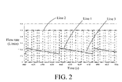
- FIG. 2 shows the comparison of a group of experimental data.
- Line 1 represents a water flow that is generated through the second water outlet 6 of the water tank 2 when a water control valve of 10 L/min is used by using the manner of the present invention.
- Line 2 represents a water flow generated by using a manner in the prior art when a water control valve for implementing a cooling function is 0.5 L/min.
- Line 3 represents a water flow in an optimal case, that is, a completely stable water flow.
- a cooling water flow generated by using the manner of the present invention already has a relatively small fluctuation, and is closer to a completely stable water flow in comparison. If a standard difference of a flow rate is used to denote the magnitude of fluctuation of a flow rate, a standard difference of the cooling water flow generated by using the manner of the present invention is only 20% of the standard difference of the cooling water flow generated by using the manner in the prior art, and the stability is significantly increased, so as to ensure the effect of a cooling function.
Landscapes
- Engineering & Computer Science (AREA)
- Textile Engineering (AREA)
- Detail Structures Of Washing Machines And Dryers (AREA)
Abstract
Description
- The present invention relates to the field of home appliances, and more particularly to a laundry drying apparatus and a method for controlling a condenser in a laundry drying apparatus.
- In a laundry drying apparatus, a drying function for laundry applies process air at high temperature to laundry for drying, in order to evaporate and remove humidity from the laundry. Humidity thus evaporated and removed as vapor may then be condensed by use of a condenser which reduces the temperature of the process air and vapor contained therein, and transforms the vapor back to humidity. Such condenser is usually a water-cooled condenser or an air-cooled condenser. The present invention relates to a water-cooled condenser, which is referred to as a condenser in short hereinafter.
- The control of a condenser mainly includes a cooling function for condensing vapor, and a washing function for cleaning the condenser from fluff which is a fine particular matter extracted from the laundry being dried by the process air and retained in the condenser by means of the condensed humidity. In cooling, a relatively small water flow is mainly fed to the condenser. With the water consumption thus required, a more stable water flow achieves a better cooling effect. Because washing is to clean impurities and sediments as fluff and possibly also residuals from washing liquids in the condenser, a relatively large water flow needs to be fed to the condenser. In an existing laundry drying apparatus, two different water control valves are used to implement a cooling function and a washing function for a condenser. For example, when the cooling function is implemented, a water control valve allowing a water flow of 0.5 l/min (liter/minute) or 0.25 l/min is used, and switching timing of that water control valve is controlled to achieve a water flow required; when the washing function is implemented, a water control valve allowing 10 l/min or 8 l/min is used to wash the condenser.
- In the according implementation manner of this prior art, in one aspect, two water control valves need to be disposed, and in another aspect, a water control valve having a small flow rate for implementing a cooling function may have problems of relatively low precision of a flow rate allowance. Further, easy formation of sediments in a high temperature working environment might further affect precision.
- In view of this, the present invention provides a laundry drying apparatus and a method for controlling a condenser in a laundry drying apparatus, so as to implement a cooling function and a washing function for a condenser by using one water control valve.
- The specific technical solution is as follows:
- The present invention provides a laundry drying apparatus, which includes a condenser, and the laundry drying apparatus further includes: a water control valve and a water tank. The water control valve is connected to a water inlet of the water tank, the water tank includes a first water outlet and a second water outlet, wherein the first water outlet and the second water outlet are separately connected to the condenser, and the position of the first water outlet on the water tank is higher than that of the second water outlet, as determined relative to a direction of gravity.
- According to the invention, a selection between a cooling function and a cleaning function is enabled by providing a water tank between the water inlet and the condenser, and a water control valve that may control admission of water to the water tank as follows: If cooling the condenser is desired, the admission of water to the water tank is limited for enabling flow of water through the second outlet only, thereby effecting the desired cooling. In this mode of operation the admission of water has to be limited to the flow that can leave the water tank through the second outlet without further increase of water level in the water tank. If washing the condenser is desired, then the admission of water is increased, so as to raise the level of water in the water tank from the second outlet to the first outlet, thereby enabling flow of water through the first outlet in addition to the second outlet, for effecting the desired washing.
- According to a preferred implementation manner of the present invention, the water control valve is directly installed on the water inlet of the water tank, or the water control valve is connected to the water inlet of the water tank through a pipe.
- According to a preferred implementation manner of the present invention, the water tank further includes a vent hole.
- According to a preferred implementation manner of the present invention, the vent hole is located below the water inlet.
- According to a preferred implementation manner of the present invention, the first water outlet and the second water outlet are integrated on the condenser, or the first water outlet and the second water outlet are connected to the condenser through pipes.
- According to a preferred implementation manner of the present invention, a flow section of the first water outlet is larger than a flow section of the second water outlet; or, the number of the first water outlets is greater than the number of the second water outlets.
- The present invention further provides a method for controlling a condenser in a laundry drying apparatus, the laundry drying apparatus further comprising a water control valve and a water tank, wherein the water control valve is connected to a water inlet of the water tank, the water tank comprises a first water outlet and a second water outlet, the first water outlet and the second water outlet are separately connected to the condenser, and the position of the first water outlet on the water tank is higher than that of the second water outlet, as determined relative to a direction of gravity, the method which includes:
- controlling a water control valve to feed water to a water tank through a water inlet of the water tank; when a water level in the water tank reaches a second water outlet on the water tank, water flowing out of the second water outlet to cool the condenser; and, when the water level in the water tank reaches a first water outlet on the water tank, water flowing out of the first water outlet to wash the condenser.
- According to a preferred implementation manner of the present invention, a flow section of the first water outlet is larger than a flow section of the second water outlet; or, the number of the first water outlets is greater than the number of the second water outlets.
- According to a preferred implementation manner of the present invention, when a cooling function for the condenser is enabled, switching timing of the water control valve is controlled as follows: an ON duration is not longer than V/(m-m1), an OFF duration is not longer than time required for water in the water tank to completely flow away, where V is a water tank volume from the position of the first water outlet to a bottom portion of the water tank, m is a flow rate of the water control valve, and m1 is a flow rate of the second water outlet.
- According to a preferred implementation manner of the present invention, when a washing function for the condenser is enabled, an ON duration of the water control valve is controlled to ensure that water flows out of the first water outlet.
- As can be seen from the foregoing technical solutions, in the present invention, only one water control valve is needed to implement a cooling function and a washing function for a condenser.
- Furthermore, because a second water outlet of a water tank is used to control the size of a water flow for cooling, a water control valve having a relatively large flow rate may be used, and in this way a problem of relatively low precision of a flow rate caused by a water control valve having a small flow rate can be alleviated.
- In order to make the objectives, technical solutions, and advantages of the present invention more comprehensible, the present invention is described in further detail below with reference to the accompanying drawing and specific embodiments. The disclosure will become more fully understood from the detailed description given herein below for illustration only, and thus are not limitative of the disclosure. In the drawing:
-
FIG. 1 is a schematic structural diagram of a laundry drying apparatus provided in an embodiment of the present invention; and -
FIG. 2 is a comparison diagram of cooling water flow rates generated in a group of different manners provided in an embodiment of the present invention. - In the laundry drying apparatus, one
water control valve 1 and awater tank 2 are used to implement functions that are originally implemented by two water control valves. As shown inFIG. 1 , a laundry drying apparatus includes a condenser 0, and further includes awater control valve 1 and awater tank 2. In this embodiment, thewater tank 2 is on a right side of the condenser 0; however, this embodiment is not limited to such a position disposal relationship. In addition, it should be noted that members inFIG. 1 are all schematically represented, and are not intended to limit the shapes of the members in a practical case. For example, the condenser 0 is schematically represented by a segment of pipe, and is not intended to limit the condenser in a practical case. - A
water inlet 3 is provided at a top portion of thewater tank 2 inFIG. 1 . Thewater control valve 1 is connected to thewater inlet 3. Multiple connect manners may be used for thewater control valve 1 and thewater inlet 3. For example, thewater control valve 1 may be directly installed on thewater inlet 3, or thewater control valve 1 may also be connected to thewater inlet 3 through a pipe. Thewater control valve 1 controls water to be fed to thewater tank 2 through thewater inlet 3. - In the process in which the
water control valve 1 controls water to be fed to thewater tank 2 through thewater inlet 3, a water backflow may occur for abnormal causes such as pressure. If water in the backflow contains pollutants, the Deutsche Vereinigung des Gasund Wasserfaches (DVGW) test requirements fail to be met. Therefore, preferably, avent hole 4 may be provided on thewater tank 2 to prevent a water backflow. Certainly, if the DVGW test requirements are not taken into consideration, or the DVGW test requirements can be met in other manners, thevent hole 4 may also be omitted. InFIG. 1 , thevent hole 4 is disposed below thewater inlet 3. - At least two water outlets are provided on the
water tank 2. Two water outlets are used as an example inFIG. 1 . The two water outlets have a certain height difference as determined relative to a direction of gravity, and herein the water outlet having a higher position as determined relative to a direction of gravity is called afirst water outlet 5, and the water outlet having a lower position as determined relative to a direction of gravity is called asecond water outlet 6. Thefirst water outlet 5 and thesecond water outlet 6 are separately connected to the condenser 0. Specifically, thefirst water outlet 5 and thesecond water outlet 6 may be connected to the condenser 0 by using an integral structure, or may also be connected to the condenser 0 through a pipe. - When water is fed to the
water tank 2, because thesecond water outlet 6 have the lower position, when water reaches the position of thesecond water outlet 6, water flows out of thesecond water outlet 6 to the condenser 0 to implement a cooling function for the condenser 0. When a water level is higher, that is, more water is fed to thewater tank 2 to reach the position of thefirst water outlet 5, water flows out of thefirst water outlet 5 to the condenser 0 to implement a washing function for the condenser 0. - To implement the cooling function for the condenser 0, water of an amount as small as possible is needed. As shown in
FIG. 1 , thesecond water outlet 6 may be disposed at a bottom portion of thewater tank 2. In addition, because the washing function usually needs a water flow rate much larger than that the cooling function needs, in an embodiment of the present invention, a flow section of thefirst water outlet 5 may be made larger than a flow section of thesecond water outlet 6. For example, if a circular hole is used for two water outlets, the hole diameter of thefirst water outlet 5 may be set to be greater than that of the hole diameter, so that a relatively small water flow flows out of thesecond water outlet 6, and a relatively large water flow flows out of thefirst water outlet 5, so as to separately meet requirements for cooling and washing. - Moreover, in a further implementation manner, that is, the number of the
first water outlets 5 is greater than the number of thesecond water outlets 6, for example, 5first water outlets 5 are disposed, and onesecond water outlet 6 is disposed; in this way, a water flow flowing out of thefirst water outlet 5 to the condenser 0 is also relatively large, and a water flow flowing out of thesecond water outlet 6 to the condenser 0 is relatively small, so as to meet separately meet requirements for cooling and washing. - Certainly, the flow section of the
first water outlet 5 is greater than the flow section of thesecond water outlet 6, and the number of thefirst water outlets 5 is greater than the number of thesecond water outlets 6. These two manners may be used at the same time. Specifically, the sizes of the flow sections and the numbers of thefirst water outlets 5 and thesecond water outlets 6 may be determined according to practical water amount demands of cooling water and washing water. - When the cooling function for the condenser 0 needs to be implemented, that is, when the cooling function for the condenser 0 is enabled, a relatively low ON timing of the
water control valve 1 needs to be controlled as follows for implementation: An ON duration is not longer than V/(m-m1), where V is a water tank volume from the position of thefirst water outlet 5 to a bottom portion of thewater tank 2, m is a flow rate of thewater control valve 1, and m1 is a flow rate of thesecond water outlet 6; the objective is to make that the water level of water fed in thewater tank 2 is not higher than thefirst water outlet 5, so as to prevent water from flowing out of thefirst water outlet 5. An OFF duration is not longer than time required for water in thewater tank 2 to completely flow away; the objective to produce a flow interruption, so as to ensure that cooling water flowing to the condenser 0 is as stable as possible. - When the washing function for the condenser 0 needs to be implemented, that is, when the washing function for the condenser 0 is enabled, an ON duration of the
water control valve 1 needs to be controlled to ensure that water flows out of thefirst water outlet 5; for example, the ON duration of thewater control valve 1 may be made to be longer than V/(m-m1). When water already exists in thewater tank 2, the duration of feeding water may be properly reduced. The specific ON duration may be decided according to washing demands. In this way, water flows out of thefirst water outlet 5 to generate a relatively large water flow to be fed to the condenser 0, so as to implement the washing function for the condenser 0. - The
water control valve 1 may be selected according to a specific volume of thewater tank 2 and opening sizes of thefirst water outlet 5 and thesecond water outlet 6. A recommended range is 2 L/min to 15 L/min. - A cooling function is a relatively important and precise function for the control of the condenser 0, a more stable water flow achieves a better cooling effect.
FIG. 2 shows the comparison of a group of experimental data. InFIG. 2 ,Line 1 represents a water flow that is generated through thesecond water outlet 6 of thewater tank 2 when a water control valve of 10 L/min is used by using the manner of the present invention.Line 2 represents a water flow generated by using a manner in the prior art when a water control valve for implementing a cooling function is 0.5 L/min.Line 3 represents a water flow in an optimal case, that is, a completely stable water flow. Hence, a cooling water flow generated by using the manner of the present invention already has a relatively small fluctuation, and is closer to a completely stable water flow in comparison. If a standard difference of a flow rate is used to denote the magnitude of fluctuation of a flow rate, a standard difference of the cooling water flow generated by using the manner of the present invention is only 20% of the standard difference of the cooling water flow generated by using the manner in the prior art, and the stability is significantly increased, so as to ensure the effect of a cooling function. - Hence, the following advantages may be provided by using the manner provided in the present invention:
- 1) Only one water control valve is needed to implement a cooling function and a washing function for a condenser.
- 2) Because a second water outlet of a water tank is used to control the size of a cooling water flow, a water control valve having a relatively large flow rate may be used; in this way, a problem of relatively low precision of a flow rate caused by a water control valve having a small flow rate can be alleviated.
- 3) The stability of a cooling water flow generated by using the manner provided in the present invention is also significantly increased, so as to ensure the effect of a cooling function.
- It should be understood that the above descriptions are merely preferred embodiments of the present invention, but not intended to limit the present invention. Any modification, equivalent replacement, or improvement made without departing from the spirit and principle of the present invention should fall within the protection scope of the present invention.
-
- 0
- Condenser
- 1
- Water control valve
- 2
- Water tank
- 3
- Water inlet
- 4
- Vent hole
- 5
- First water outlet
- 6
- Second water outlet
Claims (10)
- A laundry drying apparatus comprising a condenser (0), characterized in that the laundry drying apparatus further comprises: a water control valve (1) and a water tank (2), wherein:the water control valve (1) is connected to a water inlet (3) of the water tank (2),the water tank (2) comprises a first water outlet (5) and a second water outlet (6),the first water outlet (5) and the second water outlet (6) are separately connected to the condenser (0), andthe position of the first water outlet (5) on the water tank (2) is higher than that of the second water outlet (6), as determined relative to a direction of gravity.
- The laundry drying apparatus according to claim 1, characterized in that the water control valve (1) is directly installed on the water inlet (3), or the water control valve (1) is connected to the water inlet (3) of the water tank (2) through a pipe.
- The laundry drying apparatus according to claim 1, characterized in that the water tank (2) further comprises a vent hole (4).
- The laundry drying apparatus according to claim 3, characterized in that the vent hole (4) is located below the water inlet (3).
- The laundry drying apparatus according to claim 1, characterized in that the first water outlet (5) and the second water outlet (6) are integrated on the condenser (0), or the first water outlet (5) and the second water outlet (6) are connected to the condenser (0) through pipes.
- The laundry drying apparatus according to claim 1, characterized in that a flow section of the first water outlet (5) is larger than a flow section of the second water outlet (6); or, the number of the first water outlets (5) is greater than the number of the second water outlets (6).
- A method for controlling a condenser (0) in a laundry drying apparatus, the laundry drying apparatus further comprising a water control valve (1) and a water tank (2), wherein the water control valve (1) is connected to a water inlet (3) of the water tank (2), the water tank (2) comprises a first water outlet (5) and a second water outlet (6), the first water outlet (5) and the second water outlet (6) are separately connected to the condenser (0), and the position of the first water outlet (5) on the water tank (2) is higher than that of the second water outlet (6), as determined relative to a direction of gravity,
characterized in that the method comprises:controlling a water control valve (1) to feed water to the water tank (2) through the water inlet (3), such as:when a water level in the water tank (2) reaches the second water outlet (6) on the water tank (2), water flowing out of the second water outlet (6) cools the condenser (0); andwhen the water level in the water tank (2) reaches the first water outlet (5) of the water tank (2), water flowing out of the first water outlet (5) washes the condenser (0). - The method according to claim 7, characterized in that a flow section of the first water outlet (5) is larger than a flow section of the second water outlet (6); or, the number of the first water outlets (5) is greater than the number of the second water outlets (6).
- The method according to one of claims 7 and 8, characterized in that when a cooling function for the condenser (0) is enabled, switching timing of the water control valve (1) is controlled as follows: an ON duration is not longer than V/(m-m1), and an OFF duration is not longer than time required for water in the water tank (2) to completely flow away, wherein V is a water tank volume from the position of the first water outlet (5) to a bottom portion of the water tank (2), m is a flow rate of the water control valve (1), and m1 is a flow rate of the second water outlet (6).
- The method according to one of claims 7 and 8, characterized in that, when a washing function for the condenser (0) is enabled, an ON duration of the water control valve (1) is controlled to ensure that water flows out of the first water outlet (5).
Applications Claiming Priority (1)
| Application Number | Priority Date | Filing Date | Title |
|---|---|---|---|
| CN201310608884.4A CN104674532B (en) | 2013-11-26 | 2013-11-26 | Cloth drying device and the method for controlling condenser in cloth drying device |
Publications (2)
| Publication Number | Publication Date |
|---|---|
| EP2883997A1 true EP2883997A1 (en) | 2015-06-17 |
| EP2883997B1 EP2883997B1 (en) | 2016-09-21 |
Family
ID=51900802
Family Applications (1)
| Application Number | Title | Priority Date | Filing Date |
|---|---|---|---|
| EP14193589.0A Active EP2883997B1 (en) | 2013-11-26 | 2014-11-18 | Laundry drying apparatus and method for controlling a condenser in a laundry drying apparatus |
Country Status (2)
| Country | Link |
|---|---|
| EP (1) | EP2883997B1 (en) |
| CN (1) | CN104674532B (en) |
Families Citing this family (5)
| Publication number | Priority date | Publication date | Assignee | Title |
|---|---|---|---|---|
| CN106120278B (en) * | 2016-08-25 | 2018-08-17 | 海信(山东)冰箱有限公司 | A kind of washing-drying integral machine and its drying control method |
| CN111623561A (en) * | 2019-02-27 | 2020-09-04 | 青岛海尔滚筒洗衣机有限公司 | A kind of heat pump type clothes dryer heat pump system cooling method and heat pump type clothes dryer |
| DE102020108714A1 (en) * | 2020-03-30 | 2021-09-30 | Miele & Cie. Kg | Method for operating a washing machine and washing machine |
| CN113846473B (en) * | 2020-06-28 | 2024-07-16 | 苏州三星电子有限公司 | Condensation nozzles and washers |
| CN117188121A (en) * | 2022-05-30 | 2023-12-08 | 无锡小天鹅电器有限公司 | Dehumidification subassembly and clothing treatment facility |
Citations (2)
| Publication number | Priority date | Publication date | Assignee | Title |
|---|---|---|---|---|
| EP0340403A2 (en) * | 1988-05-04 | 1989-11-08 | A. MERLONI S.p.A. | Cleaning device for an air circulating conduit, particularly for drying assemblies of washing and drying machines |
| GB2228308A (en) * | 1989-02-17 | 1990-08-22 | Servis Group Limited | Drying machine with water spray condenser |
Family Cites Families (6)
| Publication number | Priority date | Publication date | Assignee | Title |
|---|---|---|---|---|
| JP3346993B2 (en) * | 1996-09-13 | 2002-11-18 | 株式会社東芝 | Washing and drying machine |
| JP4457524B2 (en) * | 2001-06-05 | 2010-04-28 | パナソニック株式会社 | Washing and drying machine |
| CN100519911C (en) * | 2004-11-30 | 2009-07-29 | 乐金电子(天津)电器有限公司 | Drum washing machine |
| DE102007016074A1 (en) * | 2007-04-03 | 2008-10-09 | BSH Bosch und Siemens Hausgeräte GmbH | Method and device for cleaning a component, in particular an evaporator of a condenser device, and laundry or tumble dryer with such a device |
| JP2009061217A (en) * | 2007-09-10 | 2009-03-26 | Toshiba Corp | Clothes dryer |
| CN102995369A (en) * | 2012-12-21 | 2013-03-27 | 无锡小天鹅股份有限公司 | Clothes drying machine |
-
2013
- 2013-11-26 CN CN201310608884.4A patent/CN104674532B/en not_active Expired - Fee Related
-
2014
- 2014-11-18 EP EP14193589.0A patent/EP2883997B1/en active Active
Patent Citations (2)
| Publication number | Priority date | Publication date | Assignee | Title |
|---|---|---|---|---|
| EP0340403A2 (en) * | 1988-05-04 | 1989-11-08 | A. MERLONI S.p.A. | Cleaning device for an air circulating conduit, particularly for drying assemblies of washing and drying machines |
| GB2228308A (en) * | 1989-02-17 | 1990-08-22 | Servis Group Limited | Drying machine with water spray condenser |
Also Published As
| Publication number | Publication date |
|---|---|
| CN104674532A (en) | 2015-06-03 |
| EP2883997B1 (en) | 2016-09-21 |
| CN104674532B (en) | 2018-01-09 |
Similar Documents
| Publication | Publication Date | Title |
|---|---|---|
| EP2883997B1 (en) | Laundry drying apparatus and method for controlling a condenser in a laundry drying apparatus | |
| JP5893592B2 (en) | Liquid processing equipment | |
| CN103658883B (en) | The working fluid feedway of electric discharge machining apparatus | |
| KR20190021456A (en) | Substrate processing apparatus | |
| CN103523946A (en) | Pre-treatment method of emulsion wastewater | |
| CN102976500A (en) | Improved water-softening device | |
| KR101438681B1 (en) | Evaporation condensation apparatus having foam control structure | |
| CN105509256B (en) | Water-cooled cabinet machine and condensate water control method thereof | |
| CN103982891A (en) | Pollution discharge system for steam generator in nuclear power plant and flow control method thereof | |
| CN202359640U (en) | Blow-down device for industrial circulation cooling water | |
| CN106679259A (en) | Treatment device for cooling water circulation | |
| KR20120017153A (en) | Water tank | |
| KR100643343B1 (en) | Condensate drainage system of compressor | |
| KR101500695B1 (en) | tank apparatus using improved air trap | |
| CN203518355U (en) | Liquid supply device and refrigerating unit | |
| US20170028313A1 (en) | Water purifying apparatus for purifying cooling water of power generator | |
| JP5895498B2 (en) | Turbine bypass device and turbine bypass control method | |
| JP5421022B2 (en) | Chemical liquid warming system and method for stopping the same | |
| JP6054770B2 (en) | Soft water supply equipment | |
| CN217646601U (en) | Slurry iron removing device | |
| CN204185388U (en) | Liquid reflux | |
| US10107491B2 (en) | Injection device and steam turbine system | |
| JP7438172B2 (en) | Feeding device, feeding system | |
| JP2012215314A (en) | Waste heat recovery boiler and operation method therefor | |
| JP2018130661A (en) | Water treatment equipment |
Legal Events
| Date | Code | Title | Description |
|---|---|---|---|
| PUAI | Public reference made under article 153(3) epc to a published international application that has entered the european phase |
Free format text: ORIGINAL CODE: 0009012 |
|
| 17P | Request for examination filed |
Effective date: 20141118 |
|
| AK | Designated contracting states |
Kind code of ref document: A1 Designated state(s): AL AT BE BG CH CY CZ DE DK EE ES FI FR GB GR HR HU IE IS IT LI LT LU LV MC MK MT NL NO PL PT RO RS SE SI SK SM TR |
|
| AX | Request for extension of the european patent |
Extension state: BA ME |
|
| R17P | Request for examination filed (corrected) |
Effective date: 20151217 |
|
| RBV | Designated contracting states (corrected) |
Designated state(s): AL AT BE BG CH CY CZ DE DK EE ES FI FR GB GR HR HU IE IS IT LI LT LU LV MC MK MT NL NO PL PT RO RS SE SI SK SM TR |
|
| RIC1 | Information provided on ipc code assigned before grant |
Ipc: D06F 58/28 20060101ALI20160323BHEP Ipc: D06F 58/22 20060101ALN20160323BHEP Ipc: D06F 58/24 20060101AFI20160323BHEP Ipc: D06F 81/02 20060101ALN20160323BHEP |
|
| GRAP | Despatch of communication of intention to grant a patent |
Free format text: ORIGINAL CODE: EPIDOSNIGR1 |
|
| RIC1 | Information provided on ipc code assigned before grant |
Ipc: D06F 81/02 20060101ALN20160413BHEP Ipc: D06F 58/22 20060101ALN20160413BHEP Ipc: D06F 58/24 20060101AFI20160413BHEP Ipc: D06F 58/28 20060101ALI20160413BHEP |
|
| INTG | Intention to grant announced |
Effective date: 20160502 |
|
| RIN1 | Information on inventor provided before grant (corrected) |
Inventor name: QIAN, SHANLIANG Inventor name: PANG, WENFENG Inventor name: SCHNEIDER, THOMAS Inventor name: BIRKE, HENRIK Inventor name: ZHANG, QI |
|
| GRAS | Grant fee paid |
Free format text: ORIGINAL CODE: EPIDOSNIGR3 |
|
| GRAA | (expected) grant |
Free format text: ORIGINAL CODE: 0009210 |
|
| AK | Designated contracting states |
Kind code of ref document: B1 Designated state(s): AL AT BE BG CH CY CZ DE DK EE ES FI FR GB GR HR HU IE IS IT LI LT LU LV MC MK MT NL NO PL PT RO RS SE SI SK SM TR |
|
| REG | Reference to a national code |
Ref country code: GB Ref legal event code: FG4D |
|
| REG | Reference to a national code |
Ref country code: CH Ref legal event code: EP |
|
| REG | Reference to a national code |
Ref country code: AT Ref legal event code: REF Ref document number: 831155 Country of ref document: AT Kind code of ref document: T Effective date: 20161015 |
|
| REG | Reference to a national code |
Ref country code: IE Ref legal event code: FG4D |
|
| REG | Reference to a national code |
Ref country code: DE Ref legal event code: R096 Ref document number: 602014003808 Country of ref document: DE |
|
| REG | Reference to a national code |
Ref country code: LT Ref legal event code: MG4D Ref country code: NL Ref legal event code: MP Effective date: 20160921 |
|
| PG25 | Lapsed in a contracting state [announced via postgrant information from national office to epo] |
Ref country code: FI Free format text: LAPSE BECAUSE OF FAILURE TO SUBMIT A TRANSLATION OF THE DESCRIPTION OR TO PAY THE FEE WITHIN THE PRESCRIBED TIME-LIMIT Effective date: 20160921 Ref country code: RS Free format text: LAPSE BECAUSE OF FAILURE TO SUBMIT A TRANSLATION OF THE DESCRIPTION OR TO PAY THE FEE WITHIN THE PRESCRIBED TIME-LIMIT Effective date: 20160921 Ref country code: NO Free format text: LAPSE BECAUSE OF FAILURE TO SUBMIT A TRANSLATION OF THE DESCRIPTION OR TO PAY THE FEE WITHIN THE PRESCRIBED TIME-LIMIT Effective date: 20161221 Ref country code: LT Free format text: LAPSE BECAUSE OF FAILURE TO SUBMIT A TRANSLATION OF THE DESCRIPTION OR TO PAY THE FEE WITHIN THE PRESCRIBED TIME-LIMIT Effective date: 20160921 |
|
| REG | Reference to a national code |
Ref country code: AT Ref legal event code: MK05 Ref document number: 831155 Country of ref document: AT Kind code of ref document: T Effective date: 20160921 |
|
| PG25 | Lapsed in a contracting state [announced via postgrant information from national office to epo] |
Ref country code: GR Free format text: LAPSE BECAUSE OF FAILURE TO SUBMIT A TRANSLATION OF THE DESCRIPTION OR TO PAY THE FEE WITHIN THE PRESCRIBED TIME-LIMIT Effective date: 20161222 Ref country code: SE Free format text: LAPSE BECAUSE OF FAILURE TO SUBMIT A TRANSLATION OF THE DESCRIPTION OR TO PAY THE FEE WITHIN THE PRESCRIBED TIME-LIMIT Effective date: 20160921 Ref country code: LV Free format text: LAPSE BECAUSE OF FAILURE TO SUBMIT A TRANSLATION OF THE DESCRIPTION OR TO PAY THE FEE WITHIN THE PRESCRIBED TIME-LIMIT Effective date: 20160921 Ref country code: NL Free format text: LAPSE BECAUSE OF FAILURE TO SUBMIT A TRANSLATION OF THE DESCRIPTION OR TO PAY THE FEE WITHIN THE PRESCRIBED TIME-LIMIT Effective date: 20160921 Ref country code: BE Free format text: LAPSE BECAUSE OF NON-PAYMENT OF DUE FEES Effective date: 20161130 |
|
| PG25 | Lapsed in a contracting state [announced via postgrant information from national office to epo] |
Ref country code: RO Free format text: LAPSE BECAUSE OF FAILURE TO SUBMIT A TRANSLATION OF THE DESCRIPTION OR TO PAY THE FEE WITHIN THE PRESCRIBED TIME-LIMIT Effective date: 20160921 Ref country code: EE Free format text: LAPSE BECAUSE OF FAILURE TO SUBMIT A TRANSLATION OF THE DESCRIPTION OR TO PAY THE FEE WITHIN THE PRESCRIBED TIME-LIMIT Effective date: 20160921 |
|
| PG25 | Lapsed in a contracting state [announced via postgrant information from national office to epo] |
Ref country code: BG Free format text: LAPSE BECAUSE OF FAILURE TO SUBMIT A TRANSLATION OF THE DESCRIPTION OR TO PAY THE FEE WITHIN THE PRESCRIBED TIME-LIMIT Effective date: 20161221 Ref country code: IS Free format text: LAPSE BECAUSE OF FAILURE TO SUBMIT A TRANSLATION OF THE DESCRIPTION OR TO PAY THE FEE WITHIN THE PRESCRIBED TIME-LIMIT Effective date: 20170121 Ref country code: AT Free format text: LAPSE BECAUSE OF FAILURE TO SUBMIT A TRANSLATION OF THE DESCRIPTION OR TO PAY THE FEE WITHIN THE PRESCRIBED TIME-LIMIT Effective date: 20160921 Ref country code: SK Free format text: LAPSE BECAUSE OF FAILURE TO SUBMIT A TRANSLATION OF THE DESCRIPTION OR TO PAY THE FEE WITHIN THE PRESCRIBED TIME-LIMIT Effective date: 20160921 Ref country code: BE Free format text: LAPSE BECAUSE OF FAILURE TO SUBMIT A TRANSLATION OF THE DESCRIPTION OR TO PAY THE FEE WITHIN THE PRESCRIBED TIME-LIMIT Effective date: 20160921 Ref country code: ES Free format text: LAPSE BECAUSE OF FAILURE TO SUBMIT A TRANSLATION OF THE DESCRIPTION OR TO PAY THE FEE WITHIN THE PRESCRIBED TIME-LIMIT Effective date: 20160921 Ref country code: PT Free format text: LAPSE BECAUSE OF FAILURE TO SUBMIT A TRANSLATION OF THE DESCRIPTION OR TO PAY THE FEE WITHIN THE PRESCRIBED TIME-LIMIT Effective date: 20170123 Ref country code: PL Free format text: LAPSE BECAUSE OF FAILURE TO SUBMIT A TRANSLATION OF THE DESCRIPTION OR TO PAY THE FEE WITHIN THE PRESCRIBED TIME-LIMIT Effective date: 20160921 Ref country code: SM Free format text: LAPSE BECAUSE OF FAILURE TO SUBMIT A TRANSLATION OF THE DESCRIPTION OR TO PAY THE FEE WITHIN THE PRESCRIBED TIME-LIMIT Effective date: 20160921 Ref country code: CZ Free format text: LAPSE BECAUSE OF FAILURE TO SUBMIT A TRANSLATION OF THE DESCRIPTION OR TO PAY THE FEE WITHIN THE PRESCRIBED TIME-LIMIT Effective date: 20160921 |
|
| REG | Reference to a national code |
Ref country code: DE Ref legal event code: R097 Ref document number: 602014003808 Country of ref document: DE |
|
| PG25 | Lapsed in a contracting state [announced via postgrant information from national office to epo] |
Ref country code: IT Free format text: LAPSE BECAUSE OF FAILURE TO SUBMIT A TRANSLATION OF THE DESCRIPTION OR TO PAY THE FEE WITHIN THE PRESCRIBED TIME-LIMIT Effective date: 20160921 |
|
| PLBE | No opposition filed within time limit |
Free format text: ORIGINAL CODE: 0009261 |
|
| STAA | Information on the status of an ep patent application or granted ep patent |
Free format text: STATUS: NO OPPOSITION FILED WITHIN TIME LIMIT |
|
| PG25 | Lapsed in a contracting state [announced via postgrant information from national office to epo] |
Ref country code: DK Free format text: LAPSE BECAUSE OF FAILURE TO SUBMIT A TRANSLATION OF THE DESCRIPTION OR TO PAY THE FEE WITHIN THE PRESCRIBED TIME-LIMIT Effective date: 20160921 |
|
| REG | Reference to a national code |
Ref country code: IE Ref legal event code: MM4A |
|
| REG | Reference to a national code |
Ref country code: FR Ref legal event code: ST Effective date: 20170731 |
|
| 26N | No opposition filed |
Effective date: 20170622 |
|
| PG25 | Lapsed in a contracting state [announced via postgrant information from national office to epo] |
Ref country code: LU Free format text: LAPSE BECAUSE OF NON-PAYMENT OF DUE FEES Effective date: 20161130 |
|
| PG25 | Lapsed in a contracting state [announced via postgrant information from national office to epo] |
Ref country code: FR Free format text: LAPSE BECAUSE OF NON-PAYMENT OF DUE FEES Effective date: 20161130 |
|
| PG25 | Lapsed in a contracting state [announced via postgrant information from national office to epo] |
Ref country code: SI Free format text: LAPSE BECAUSE OF FAILURE TO SUBMIT A TRANSLATION OF THE DESCRIPTION OR TO PAY THE FEE WITHIN THE PRESCRIBED TIME-LIMIT Effective date: 20160921 Ref country code: IE Free format text: LAPSE BECAUSE OF NON-PAYMENT OF DUE FEES Effective date: 20161118 |
|
| PG25 | Lapsed in a contracting state [announced via postgrant information from national office to epo] |
Ref country code: HU Free format text: LAPSE BECAUSE OF FAILURE TO SUBMIT A TRANSLATION OF THE DESCRIPTION OR TO PAY THE FEE WITHIN THE PRESCRIBED TIME-LIMIT; INVALID AB INITIO Effective date: 20141118 |
|
| PG25 | Lapsed in a contracting state [announced via postgrant information from national office to epo] |
Ref country code: MC Free format text: LAPSE BECAUSE OF FAILURE TO SUBMIT A TRANSLATION OF THE DESCRIPTION OR TO PAY THE FEE WITHIN THE PRESCRIBED TIME-LIMIT Effective date: 20160921 Ref country code: HR Free format text: LAPSE BECAUSE OF FAILURE TO SUBMIT A TRANSLATION OF THE DESCRIPTION OR TO PAY THE FEE WITHIN THE PRESCRIBED TIME-LIMIT Effective date: 20160921 Ref country code: MK Free format text: LAPSE BECAUSE OF FAILURE TO SUBMIT A TRANSLATION OF THE DESCRIPTION OR TO PAY THE FEE WITHIN THE PRESCRIBED TIME-LIMIT Effective date: 20160921 Ref country code: CY Free format text: LAPSE BECAUSE OF FAILURE TO SUBMIT A TRANSLATION OF THE DESCRIPTION OR TO PAY THE FEE WITHIN THE PRESCRIBED TIME-LIMIT Effective date: 20160921 |
|
| PG25 | Lapsed in a contracting state [announced via postgrant information from national office to epo] |
Ref country code: CH Free format text: LAPSE BECAUSE OF NON-PAYMENT OF DUE FEES Effective date: 20171130 Ref country code: LI Free format text: LAPSE BECAUSE OF NON-PAYMENT OF DUE FEES Effective date: 20171130 |
|
| PG25 | Lapsed in a contracting state [announced via postgrant information from national office to epo] |
Ref country code: MT Free format text: LAPSE BECAUSE OF NON-PAYMENT OF DUE FEES Effective date: 20161118 |
|
| PG25 | Lapsed in a contracting state [announced via postgrant information from national office to epo] |
Ref country code: AL Free format text: LAPSE BECAUSE OF FAILURE TO SUBMIT A TRANSLATION OF THE DESCRIPTION OR TO PAY THE FEE WITHIN THE PRESCRIBED TIME-LIMIT Effective date: 20160921 Ref country code: TR Free format text: LAPSE BECAUSE OF FAILURE TO SUBMIT A TRANSLATION OF THE DESCRIPTION OR TO PAY THE FEE WITHIN THE PRESCRIBED TIME-LIMIT Effective date: 20160921 |
|
| REG | Reference to a national code |
Ref country code: DE Ref legal event code: R084 Ref document number: 602014003808 Country of ref document: DE |
|
| PGFP | Annual fee paid to national office [announced via postgrant information from national office to epo] |
Ref country code: GB Payment date: 20231123 Year of fee payment: 10 |
|
| PGFP | Annual fee paid to national office [announced via postgrant information from national office to epo] |
Ref country code: DE Payment date: 20241130 Year of fee payment: 11 |
|
| GBPC | Gb: european patent ceased through non-payment of renewal fee |
Effective date: 20241118 |
|
| PG25 | Lapsed in a contracting state [announced via postgrant information from national office to epo] |
Ref country code: GB Free format text: LAPSE BECAUSE OF NON-PAYMENT OF DUE FEES Effective date: 20241118 |