EP2883971A1 - Fastening copper alloy - Google Patents
Fastening copper alloy Download PDFInfo
- Publication number
- EP2883971A1 EP2883971A1 EP12882822.5A EP12882822A EP2883971A1 EP 2883971 A1 EP2883971 A1 EP 2883971A1 EP 12882822 A EP12882822 A EP 12882822A EP 2883971 A1 EP2883971 A1 EP 2883971A1
- Authority
- EP
- European Patent Office
- Prior art keywords
- copper alloy
- alloy
- fastening
- phase
- cold
- Prior art date
- Legal status (The legal status is an assumption and is not a legal conclusion. Google has not performed a legal analysis and makes no representation as to the accuracy of the status listed.)
- Granted
Links
Images


Classifications
-
- C—CHEMISTRY; METALLURGY
- C22—METALLURGY; FERROUS OR NON-FERROUS ALLOYS; TREATMENT OF ALLOYS OR NON-FERROUS METALS
- C22C—ALLOYS
- C22C9/00—Alloys based on copper
- C22C9/04—Alloys based on copper with zinc as the next major constituent
-
- A—HUMAN NECESSITIES
- A44—HABERDASHERY; JEWELLERY
- A44B—BUTTONS, PINS, BUCKLES, SLIDE FASTENERS, OR THE LIKE
- A44B19/00—Slide fasteners
-
- A—HUMAN NECESSITIES
- A44—HABERDASHERY; JEWELLERY
- A44B—BUTTONS, PINS, BUCKLES, SLIDE FASTENERS, OR THE LIKE
- A44B19/00—Slide fasteners
- A44B19/24—Details
-
- C—CHEMISTRY; METALLURGY
- C22—METALLURGY; FERROUS OR NON-FERROUS ALLOYS; TREATMENT OF ALLOYS OR NON-FERROUS METALS
- C22F—CHANGING THE PHYSICAL STRUCTURE OF NON-FERROUS METALS AND NON-FERROUS ALLOYS
- C22F1/00—Changing the physical structure of non-ferrous metals or alloys by heat treatment or by hot or cold working
- C22F1/08—Changing the physical structure of non-ferrous metals or alloys by heat treatment or by hot or cold working of copper or alloys based thereon
-
- A—HUMAN NECESSITIES
- A44—HABERDASHERY; JEWELLERY
- A44B—BUTTONS, PINS, BUCKLES, SLIDE FASTENERS, OR THE LIKE
- A44B19/00—Slide fasteners
- A44B19/42—Making by processes not fully provided for in one other class, e.g. B21D53/50, B21F45/18, B22D17/16, B29D5/00
- A44B19/44—Securing metal interlocking members to ready-made stringer tapes
Definitions
- the present invention relates to a copper alloy for fastening used as fastening material.
- Cu-Zn-based alloys are excellent in workability and have been widely used in various fields.
- zinc base metal is generally more inexpensive than copper base metal. Therefore, material cost thereof can be reduced by increasing a zinc content.
- zinc element present in copper results in significant deterioration in corrosion resistance.
- a copper alloy having an increased zinc content is used for a fastening material which is embedded on a base fabric through cold working, there has occurred a problem of season cracking of the material due to residual work strain.
- Japanese Patent No. 4357869 discloses a technique in which an alloy contains elemental additives, such as Al, Si, Sn and/or Mn, and is surface-treated by means of shot-blasting or the like to be provided with compression stress in order to enhance season cracking resistance.
- elemental additives such as Al, Si, Sn and/or Mn
- Patent Literature 1 Japanese Patent No. 4357869
- the copper alloy described in Patent Literature 1 requires to be subjected to processing such as shot-blasting, thereby increasing numbers of the manufacturing processes, and this causes an increased manufacturing cost.
- the structure of the copper alloy is made into a single phase of ⁇ in order to obtain suitable cold-workability and an increased zinc concentration in the alloy is undesirable because of causing significant formation of ⁇ -phase, which makes cold working of the alloy difficult. Therefore, in the technique described in Patent Literature 1, season cracking resistance and cold workability of the alloy have not yet been sufficiently studied when the zinc concentration in the alloy is increased to allow the ⁇ and ⁇ phases coexist.
- the copper alloy described in Patent Literature 1 has a problem that the zinc concentration is too low to be manufactured by extrusion.
- the present invention provides a copper alloy for fastening excellent in ease of manufacturing and also excellent in season cracking resistance and cold-workability.
- a copper alloy for fastening wherein the alloy has a structure of a mixture of ⁇ -phase and a ⁇ -phase; and wherein the alloy has a composition represented by the general formula: Cu bal .Zn a Mn b , where bal., a, and b are expressed in % by mass, bal.
- a copper alloy for fastening according to the present invention is a copper alloy for fastening wherein the alloy has a structure of a mixture of ⁇ -phase and a ⁇ -phase; and wherein the alloy has a composition represented by the general formula: Cu bal .Zn a Mn b , where bal., a, and b are expressed in % by mass, bal.
- the ⁇ -phase percentage (%) in the structure is 0.1 ⁇ ⁇ ⁇ 22 as determined from the result of observation of a cross section perpendicular to the rolled surface using an integrated peak intensity ratio in X-ray diffraction.
- the mean crystal grain size in the structure is 3-14 ⁇ m.
- the pull-out strength after ammonia vapor test is 70% or more relative to that of Cu 85 Zn 15 material.
- a component article for fastening formed of the above-described copper alloy for fastening is provided.
- a copper alloy for fastening according to an embodiment of the present invention is a copper alloy of which structure consists of a mixed phase of an ⁇ -phase having a face centered cubic structure and a ⁇ -phrase having a body centered cubic structure.
- season cracking sensitivity is generally known to be higher as the amount of Zn is increased, according to the intensive studies by the present inventors, it has been found that cold-workability of 80% or more can be realized and the season cracking resistance can be also enhanced by adjusting the concentrations of zinc and elemental additives in copper in suitable ranges and controlling the heating conditions and cooling conditions upon manufacturing, thereby controlling the structure such that the structure becomes a suitable ⁇ + P phase.
- the zinc content is less than 34% by mass, the consequently increased copper content leads to a higher material cost and, for a copper-zinc-manganese ternary alloy, the manganese content is increased, thereby causing a problem that the alloy cannot be a material capable of avoiding needle detection due to the increased manganese content.
- the term "material capable of avoiding needle detection" as used herein refers to a material corresponding to a product that can satisfy the NC-B standard ( ⁇ 1.2 mm or less in terms of steel ball).
- the zinc content exceeds 40.5%, the structure in the cast material has a ⁇ -phase percentage of 50% or more and this makes the material brittle, thereby deteriorating the cold-workability of the copper alloy and easily causing brittle fracture.
- the Zn content in the copper alloy is preferably 34-40.5% by mass, more preferably 35-38.3% by mass, and still more preferably 35-38% by mass.
- Cu-Zn-based alloys have a problem that zinc element present in copper in a high concentration causes significant deterioration in corrosion resistance
- addition of Mn to copper as an additional element can effectively inhibit the season cracking of the fastening materials.
- the addition of Mn also leads to an effect to easily make the crystal grains finer, thereby enhancing the strength.
- Al, Si, Sn and the like are also generally known as elemental additives which are added for the purpose of improving characteristics of copper alloys.
- These elemental additives however, have large values of zinc equivalent, and thus addition thereof even in a very small amount may significantly change properties of the alloy in some cases. This makes it difficult to constantly control the quality of the copper alloy for fastening which is intended to be manufactured in mass production, thereby the ease of its manufacture cannot be improved.
- Mn has a zinc equivalent of 0.5 which is much smaller than those of other elemental additives such as Al, Si, and Sn. Therefore, comparing with other elemental additives, Mn can make a smaller quality difference of final products which may occur due to manufacturing errors, and thus provide a copper alloy for fastening excellent in quality stability and suitable for mass production.
- the copper alloy according to the present invention it is possible to obtain a copper alloy for fastening exhibiting both of cold-workability of 80% or more and season cracking resistance by adding Mn in an amount of 0.1% by mass or more.
- An excessively large Mn content results in deterioration in cold-workability.
- magnetization of the alloy per se may make the operation of needle detection required for the manufactured fastening material difficult.
- the amount of Mn added is 0.1-6% by mass in order to prevent a high material cost due to a reduced amount of zinc, more preferably 0.1-3.5% by mass, and still more preferably 0.2-3.0% by mass in order to satisfy the NC-A standard of needle detection (0.8 mm ⁇ or less in terms of a steel ball).
- the copper alloy for fastening according to the embodiment of the present invention has a composition represented by the general formula: Cu bal .Zn a Mn b , where bal., a, and b are expressed in % by mass, bal. represents the balance, 34 ⁇ a ⁇ 40.5, 0.1 ⁇ b ⁇ 6, and inevitable impurities may be contained, and the composition satisfying the following equations (1) and (2): b ⁇ - 8 ⁇ a + 300 / 7 , where 34 ⁇ a ⁇ 37.5 b ⁇ - 5.5 ⁇ a + 225.25 / 5 , where 35.5 ⁇ a ⁇ 40.5
- the copper alloy for fastening according to the embodiment of the present invention is a copper alloy further satisfying equations (3) and (4) below: b ⁇ - a + 38.5 , where 35 ⁇ a ⁇ 38.3 b ⁇ - a + 40.5 , where 37 ⁇ a ⁇ 38.3
- the color tone in appearance of the finally obtained copper alloy very closely approaches to that of existing Cu 85 Zn 15 alloy which the customers desire. Therefore, even when fastening materials are manufactured in mass production using the copper alloy according to the present invention, color tone changes to a lesser degree among the fastening materials. Further, the ⁇ -phase is easily controlled to a desired ratio, thereby successfully providing fastening materials at a high yield and excellent in quality stability and appearance.
- the copper alloy is a more useful material as a fastening material capable of avoiding needle detection.
- Control of the percentage of ⁇ -phase and ⁇ -phase in the copper alloy is important in order to improve season cracking resistance and cold-workability required for the fastening materials. Control of the percentage of ⁇ -phase and ⁇ -phase can be attained by adjusting the heating conditions and subsequent cooling conditions.
- the ⁇ -phase percentage (%) in the crystalline structure is 0.1 ⁇ ⁇ ⁇ 22, and more preferably 0.5 ⁇ ⁇ ⁇ 20.5.
- the reason for that is when the ⁇ -phase percentage is excessively high, the cold-workability cannot be ensured and when the ⁇ -phase percentage is excessively low, sufficient season cracking resistance cannot be obtained in spite of containing manganese.
- the mean crystal grain size in the structure is 14 ⁇ m or less, and, for example, 3-13.5 ⁇ m.
- the mean crystal grain size is not particularly limited for the lowest value, but is preferably 0.1 ⁇ m or more in order for homogeneous recrystallization.
- the copper alloy for fastening according to the embodiment of the present invention can exhibit a pull-out strength after ammonia vapor test of 70% or more relative to that of Cu 85 Zn 15 material, and for this alloy, the cold-workability can be 80% or more, and the extrusion surface pressure at 500°C can be 1100MPa or less, which corresponds to 65% or less as a percentage to that of Cu 85 Zn 15 material. It is meant by this value of the extrusion surface pressure at 500°C that the lifetime of the die can be prolonged because the yield strength at 500°C of a typical steel material for the die is approximately 1400 MPa.
- the copper alloy for fastening according to the embodiment of the present invention is not only effective in cold working processes but also is sufficiently usable in hot working processes.
- component articles for fastening suitable for the copper alloy for fastening according to the present invention are described, referring to the drawings. It is noted although the description takes parts composing a slide fastener as examples for the component articles for fastening in the following embodiment, the present invention can be similarly applied for products formed of a copper alloy other than the fastening materials described below or intermediate products prior to obtaining the final products (e.g., long wire rods described below).
- the copper alloy for fastening according to the present invention can be utilized for component articles for fastening, such as a fastener element, an top end stop, a bottom end stop, a retaining box and a slider, the copper alloy can be also utilized for a variety of fastening materials other than the parts exemplified herein, as a matter of course.
- explanations are made, taking an example of a slide fastener 1.
- the slide fastener 1 includes, for example as shown in Figure 1 , a pair of right and left fastener stringers 2 on which element rows 4 are formed by attaching a plurality of fastener elements 10 in rows on the side edges of fastener tapes 3 opposing to each other, top end stops 5 and bottom end stop 6 attached at the top end parts and the bottom end parts of the right and left fastener stringers 2 along with the element rows 4, respectively, and a slider 7 slidably arranged along with the element rows 4.
- Each fastener element 10 is manufactured by, as shown in Figure 2 , slicing a wire rod 20 having a generally Y-shaped cross section, referred to as Y-bar, at a predetermined thickness, and subjecting the sliced element material 21 to press working or the like to form an engaging head 10a.
- the fastener element 10 includes the engaging head 10a formed by press working or the like, a body part 10 extended in one direction from the engaging head 10a, and a pair of leg parts 10c bifurcated and extended from the body part 10b.
- the fastener elements 10 are attached to the fastener tape 3 at predetermined intervals by caulking the leg parts 10c in a direction in which both of the leg parts 10c approach to each other (inward) to plastically deform the leg parts 10c in a state where the element-attaching part of the fastener tape 3 including a core string part 3a has been inserted between a pair of the leg parts 10c.
- the top end stop 5 for the slide fastener 1 is manufactured by slicing a flat rectangle 5a having a rectangular-shaped cross section at a predetermined thickness and bending the obtained cut piece to form an article having a generally U-shaped cross section.
- the top end stop 5 is attached to each of the right and left fastener tapes 3 by caulking the top end stop 5 to plastically deform the top end stop 5 in a state where the element-attaching part of the fastener tape 3 has been inserted into the space at the inner surface side of the top end stop 5.
- the bottom end stop 6 for the slide fastener 1 is manufactured by slicing a deformed wire rod 6a having a generally H-shaped (or generally X-shaped) cross section at a predetermined thickness.
- the bottom end stop 6 is attached to the right and left fastener tapes 3 straddling the both tapes by caulking the bottom end stop 6 to plastically deform the bottom end stop 6 in a state where the element-attaching parts of the right and left fastener tapes 3 have been inserted into the spaces at the inner surface side of the right and left parts of the bottom end stop 6, respectively.
- the fastening materials such as fastener element 10, the top end stop 5, the bottom end stop 6 and the slider 7, are often subjected to cold-working and have tensile residual stress caused by this cold-working, and therefore season cracking has often happened for the alloys containing a large amount of zinc.
- the alloy can be that can realize cold-workability of 80% or more and is excellent in season cracking resistance by adjusting the concentrations of zinc and the elemental additives in copper in suitable ranges and controlling the heating conditions and cooling conditions upon manufacturing, thereby controlling the structure such that the structure becomes a suitable ⁇ + ⁇ phase.
- a copper-zinc alloy casting material having a predetermined cross-sectional area is manufactured.
- the casting material is cast, while adjusting the copper-zinc alloy composition such that the zinc content is preferably 34-40.5% by mass, more preferably 35-38.3% by mass, and still more preferably 35-38% by mass.
- the percentage of the ⁇ -phase and the ⁇ -phase in the copper-zinc alloy is controlled such that the ⁇ -phase percentage is 0.1 ⁇ ⁇ ⁇ 22, more preferably 0.5 ⁇ ⁇ ⁇ 20.5 by subjecting the casting material to cold wire drawing into a wire rod having a desired wire diameter and to heat treatment.
- the conditions of the heat treatment to which the casting material is subjected can be arbitrarily set depending on the composition of the copper-zinc alloy.
- a long wire rod which is an intermediate product, is manufactured by subjecting the cast material to cold working such as cold extrusion such that the working reduction percentage is, for example, 80% or more.
- the cold working is carried out at a temperature below the recrystallization temperature of the copper-zinc alloy, and it is preferred to carry out the cold working at a temperature of 200°C or below, and particularly at a temperature of 100°C or below.
- the above-described Y-bar 20 is formed by passing the cold-worked long wire rod through a plurality of rolling rolls to perform cold working such that the cross section of the wire rod becomes a generally Y-shape.
- the fastener element 10 according to the present embodiment can be manufactured by slicing Y-bar 20 at a predetermined thickness and subjecting the sliced element material 21 to press work using a forming punch and a forming die or the like to form the engaging head 10a. It is noted that deformed wire rods such as the Y-bar can be also directly manufactured by directly extruding the casting material at 400°C or above since the copper alloy according to the present invention is also excellent in hot-extrudability.
- top end stop 5 In the case of the top end stop 5, first a casting material made of a copper-zinc alloy having the similar composition to that of the fastener element 10 is cast, and then the casting material is subjected to heat treatment to control the ⁇ -phase percentage in the copper-zinc alloy. Subsequently, the obtained casting material is subjected to cold working to manufacture a flat rectangle 5a (intermediate product) having a rectangular-shaped cross section. Then the top end stop 5 can be manufactured by slicing the obtained flat rectangle 5a at a predetermined thickness as shown in Figure 2 and bending the obtained cut piece to form an article having a generally U-shaped cross section.
- the bottom end stop 6 first a casting material made of a copper-zinc alloy having a similar composition to that of the fastener element 10 and the top end stop 5 is cast, and then the casting material is subjected to heat treatment to control the ⁇ -phase percentage in the copper-zinc alloy. Subsequently, the obtained casting material is subjected to cold working to manufacture a deformed wire rod 6a (intermediate product) having a generally H-shaped (or generally X-shaped) cross section. Then the bottom end stop 6 can be manufactured by slicing the obtained deformed wire rod 6a at a predetermined thickness as shown in Figure 2 .
- the plate material was subjected to heat treatment at a temperature in the range of 400°C or above to 700°C or below and then the heat-treated plate material was annealed.
- the plate material in which work strain was removed by the heat treatment was subjected to cold rolling where the plate material was rolled only from the vertical directions to manufacture a long plate material having a thickness of 1 mm or less.
- Test pieces with a plate thickness of 0.8 mm, a plate width of 10 mm, and a plate length of predetermined value (length in the rolling direction) were cut from the resulting plate material.
- the plate material having a plate thickness of 4.0-4.2 mm obtained by the above-described process was subjected to air annealing at 500°C for 6 hours, and then the plate-like test pieces were subjected to milling in order to remove an oxide film formed on the surface, and to finishing the surface with SiC water-proof polishing paper (#800) to manufacture the test pieces for cold workability evaluation.
- the finished dimensions of the test piece for cold-workability evaluation were a plate thickness of 3.5 mm, a plate width of 7.5 mm, and a plate length of a predetermined value.
- Copper, zinc, and various elemental additives were weighed so as to make the alloy compositions as shown in Table 1, these ingredients were melted under an argon atmosphere using a high frequency vacuum melting apparatus to manufacture an ingot (a billet) having a diameter of 40 mm.
- An extruder container 31 shown in Figure 3 was set at 500°C and the billet 32 was heated in an atmospheric furnace set at 800°C for 30 minutes, and then the billet 32 was inserted into the extruder container (inner diameter 42 mm ⁇ ).
- a stem 33 was arranged on the billet 32, the billet 32 was pressed by the stem 33 to be extruded through a die 34 for a 8 mm ⁇ material arranged on the front face of the extruder container 31, the maximum load during the extrusion was measured, the maximum surface pressure was calculated from the maximum load, and "Extrusion surface pressure at 500°C" was defined as this maximum surface pressure.
- the exposure test to ammonia was carried out according to Japan Copper and Brass Association Technical Standard JBMA-T301, Ammonia test method of copper alloy wrought material (JBMA method). It is noted that fastener chains of No. 5 were exposed to ammonia atmosphere, washed and then used as test pieces for evaluation of the fastener product. The resulting elements of the fastener chains as the test pieces were stretched by a tensile testing machine, and the obtained mean value of the load was defined as the mean pull-out strength. The results are shown in Table 1.
- Needle detection performance was evaluated using the test pieces used in ⁇ Evaluation of mean pull-out strength after exposure to ammonia> described above.
- NC-A Comparative Example 2 65 35 0 0 0 0 0 Pass at 80% or more 1191 Poor 15.7 NC-A Comparative Example 3 60.6 39.4 0 0 0 14 Pass at 80% or more 924 Poor 7.9 NC-A Comparative Example 4 59.5 40.5 0 0 0 23 Pass at 80% or more 877 Fair 9.0 NC-A Comparative Example 5 59.2 40.8 0 0 0 0 29 Pass at 80% or more 812 Fair 11.3 NC-A Comparative Example 6 60.6 39.4 0 0 0 39 Pass at 80% or more 924 Fair 7.4 NC-A Comparative Example 7 61.2 38.8 0 0 0 0 40 39% 1063 Poor Not evaluable Not evaluable Comparative Example 8 58 42 0 0 0 0 45 39% 689 Poor Not evaluable Not evaluable Comparative Example 9 65.5 34 0.5 0 0 0 0 Pass at 80% or more 1250 Poor 14.2 NC-
- Comparative Example 1 is excellent in cold-workability and season cracking resistance but has a low zinc concentration, thereby increasing the material cost. In addition, Comparative Example 1 exhibited a high extrusion surface pressure at 500°C, and therefore production using extrusion is difficult.
- Comparative Examples 7 and 8 exhibited a draft limit of only about 39% and are inferior in cold workability due to the ⁇ -phase percentage as high as 40%. In addition, both of Comparative Examples 7 and 8 did not exhibit high cold-workability comparable to that for Examples 1-9 but exhibited too low cold-workability to make the test pieces for ammonia vapor test, and the test pieces could not be made in a state of having residual stress after cold working, thereby failing in evaluation of the crystal grain size.
- Both of Comparative Examples 9 and 10 do not have structure of the mixed phase of ⁇ + ⁇ phase and also are inferior in season cracking resistance in spite of addition of Mn as an additional element.
- Comparative Examples 12-17 show examples added with A1 as an additional element. All of Comparative Examples 12-17 did not exhibit high cold-workability comparable to that for Examples 1-9 but exhibited too low cold-workability to make the test pieces for ammonia vapor test, and the test pieces could not be made in a state of having residual stress after cold working.
- Comparative Examples 18-23 are examples added with Si as an additional element and Comparative Examples 24-28 are examples added with Sn as an additional element. All of Comparative Examples 18-28 did not exhibit high cold-workability comparable to that for Examples 1-9 but exhibited too low cold-workability to make the test pieces for ammonia vapor test.
- Comparative Example 29 is an example which has a composition within the composition range of the present invention and a higher ⁇ -phase percentage. Similarly to the above, Comparative Example 29 did not exhibit high cold-workability comparable to Examples but exhibited too low cold-workability to make the test pieces for ammonia vapor test.
Landscapes
- Chemical & Material Sciences (AREA)
- Engineering & Computer Science (AREA)
- Materials Engineering (AREA)
- Mechanical Engineering (AREA)
- Metallurgy (AREA)
- Organic Chemistry (AREA)
- Physics & Mathematics (AREA)
- Thermal Sciences (AREA)
- Crystallography & Structural Chemistry (AREA)
- Slide Fasteners (AREA)
- Conductive Materials (AREA)
Description
- The present invention relates to a copper alloy for fastening used as fastening material.
- Cu-Zn-based alloys are excellent in workability and have been widely used in various fields. With regard to Cu-Zn-based alloys, zinc base metal is generally more inexpensive than copper base metal. Therefore, material cost thereof can be reduced by increasing a zinc content. There exists a problem, however, that zinc element present in copper results in significant deterioration in corrosion resistance. In particular, when a copper alloy having an increased zinc content is used for a fastening material which is embedded on a base fabric through cold working, there has occurred a problem of season cracking of the material due to residual work strain.
- Japanese Patent No.
4357869 - [Patent Literature 1] Japanese Patent No.
4357869 - However, the copper alloy described in Patent Literature 1 requires to be subjected to processing such as shot-blasting, thereby increasing numbers of the manufacturing processes, and this causes an increased manufacturing cost. In addition, according to Patent Literature 1, the structure of the copper alloy is made into a single phase of α in order to obtain suitable cold-workability and an increased zinc concentration in the alloy is undesirable because of causing significant formation of β-phase, which makes cold working of the alloy difficult. Therefore, in the technique described in Patent Literature 1, season cracking resistance and cold workability of the alloy have not yet been sufficiently studied when the zinc concentration in the alloy is increased to allow the α and β phases coexist. In addition, the copper alloy described in Patent Literature 1 has a problem that the zinc concentration is too low to be manufactured by extrusion.
- In view of the problems described above, the present invention provides a copper alloy for fastening excellent in ease of manufacturing and also excellent in season cracking resistance and cold-workability.
- According to an aspect of the present invention, in order to solve the problems described above, a copper alloy for fastening is provided, wherein the alloy has a structure of a mixture of α-phase and a β-phase; and wherein the alloy has a composition represented by the general formula: Cubal.ZnaMnb, where bal., a, and b are expressed in % by mass, bal. represents the balance, 34 ≤ a ≤ 40.5, 0.1 ≤ b ≤ 6, and inevitable impurities may be contained; and the composition satisfying the following equations (1) and (2):


- In one embodiment, a copper alloy for fastening according to the present invention is a copper alloy for fastening wherein the alloy has a structure of a mixture of α-phase and a β-phase; and wherein the alloy has a composition represented by the general formula: Cubal.ZnaMnb, where bal., a, and b are expressed in % by mass, bal. represents the balance, 35 ≤ a ≤ 38.3, 0.2 ≤ b ≤ 3.5, and inevitable impurities may be contained; and the composition satisfying the following equations (3) and (4):


- In another embodiment of the copper alloy for fastening according to the present invention, the β-phase percentage (%) in the structure is 0.1 ≤ β ≤ 22 as determined from the result of observation of a cross section perpendicular to the rolled surface using an integrated peak intensity ratio in X-ray diffraction.
- In still another embodiment of the copper alloy for fastening according to the present invention, the mean crystal grain size in the structure is 3-14 µm.
- In yet another embodiment of the copper alloy for fastening according to the present invention, the pull-out strength after ammonia vapor test is 70% or more relative to that of Cu85Zn15 material.
- According to another aspect of the present invention, a component article for fastening formed of the above-described copper alloy for fastening is provided.
- According to the present invention, it is possible to provide a copper alloy for fastening excellent in ease of manufacturing and also excellent in season cracking resistance and cold-workability.
-
-
Figure 1 is a plane view showing an example of a slide fastener using a copper alloy for fastening according to an embodiment of the present invention; -
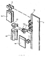
Figure 2 is a perspective view illustrating attachment of fastener elements and top end and bottom end stops using a copper alloy for fastening according to an embodiment of the present invention to a fastener tape; and -
Figure 3 is a cross sectional view showing an extrusion part of an extrusion container used to measure an extrusion surface pressure at 500°C for a copper alloy. - A copper alloy for fastening according to an embodiment of the present invention is a copper alloy of which structure consists of a mixed phase of an α-phase having a face centered cubic structure and a β-phrase having a body centered cubic structure. Although season cracking sensitivity is generally known to be higher as the amount of Zn is increased, according to the intensive studies by the present inventors, it has been found that cold-workability of 80% or more can be realized and the season cracking resistance can be also enhanced by adjusting the concentrations of zinc and elemental additives in copper in suitable ranges and controlling the heating conditions and cooling conditions upon manufacturing, thereby controlling the structure such that the structure becomes a suitable α + P phase.
- When the zinc content is less than 34% by mass, the consequently increased copper content leads to a higher material cost and, for a copper-zinc-manganese ternary alloy, the manganese content is increased, thereby causing a problem that the alloy cannot be a material capable of avoiding needle detection due to the increased manganese content. The term "material capable of avoiding needle detection" as used herein refers to a material corresponding to a product that can satisfy the NC-B standard (φ 1.2 mm or less in terms of steel ball). When the zinc content exceeds 40.5%, the structure in the cast material has a β-phase percentage of 50% or more and this makes the material brittle, thereby deteriorating the cold-workability of the copper alloy and easily causing brittle fracture. The Zn content in the copper alloy is preferably 34-40.5% by mass, more preferably 35-38.3% by mass, and still more preferably 35-38% by mass.
- Although Cu-Zn-based alloys have a problem that zinc element present in copper in a high concentration causes significant deterioration in corrosion resistance, addition of Mn to copper as an additional element can effectively inhibit the season cracking of the fastening materials. The addition of Mn also leads to an effect to easily make the crystal grains finer, thereby enhancing the strength.
- It is noted that Al, Si, Sn and the like are also generally known as elemental additives which are added for the purpose of improving characteristics of copper alloys. These elemental additives, however, have large values of zinc equivalent, and thus addition thereof even in a very small amount may significantly change properties of the alloy in some cases. This makes it difficult to constantly control the quality of the copper alloy for fastening which is intended to be manufactured in mass production, thereby the ease of its manufacture cannot be improved. On the contrary, Mn has a zinc equivalent of 0.5 which is much smaller than those of other elemental additives such as Al, Si, and Sn. Therefore, comparing with other elemental additives, Mn can make a smaller quality difference of final products which may occur due to manufacturing errors, and thus provide a copper alloy for fastening excellent in quality stability and suitable for mass production.
- With regard to the copper alloy according to the present invention, it is possible to obtain a copper alloy for fastening exhibiting both of cold-workability of 80% or more and season cracking resistance by adding Mn in an amount of 0.1% by mass or more. An excessively large Mn content results in deterioration in cold-workability. In addition, magnetization of the alloy per se may make the operation of needle detection required for the manufactured fastening material difficult. Preferably, the amount of Mn added is 0.1-6% by mass in order to prevent a high material cost due to a reduced amount of zinc, more preferably 0.1-3.5% by mass, and still more preferably 0.2-3.0% by mass in order to satisfy the NC-A standard of needle detection (0.8 mmφ or less in terms of a steel ball).
- Preferably, the copper alloy for fastening according to the embodiment of the present invention has a composition represented by the general formula: Cubal.ZnaMnb, where bal., a, and b are expressed in % by mass, bal. represents the balance, 34 ≤ a ≤ 40.5, 0.1 ≤ b ≤ 6, and inevitable impurities may be contained, and
the composition satisfying the following equations (1) and (2):

- The reason why the relationship between respective compositions is determined as represented by equations (1) and (2) is that it is difficult to realize both of cold-workability and season cracking resistance necessary for the fastening material in the case of not satisfying equations (1) and (2). More specifically, when the concentration of Mn does not satisfy equation (1), i.e., b < (-8a + 300)/7, the copper alloy can be worked more easily, but may be cracked more often upon exposure to a corrosive environment such as ammonia. On the other hand, when the concentration of Mn does not satisfy equation (2), i.e., b > (-5.5a + 225.25)/5, the structure becomes brittle and cold-workability is deteriorated though less cracking occurs.
- More preferably, the copper alloy for fastening according to the embodiment of the present invention is a copper alloy further satisfying equations (3) and (4) below:


- When the copper alloy has a composition satisfying equations (3) and (4), the color tone in appearance of the finally obtained copper alloy very closely approaches to that of existing Cu85Zn15 alloy which the customers desire. Therefore, even when fastening materials are manufactured in mass production using the copper alloy according to the present invention, color tone changes to a lesser degree among the fastening materials. Further, the β-phase is easily controlled to a desired ratio, thereby successfully providing fastening materials at a high yield and excellent in quality stability and appearance. In addition, the copper alloy is a more useful material as a fastening material capable of avoiding needle detection.
- Control of the percentage of α-phase and β-phase in the copper alloy is important in order to improve season cracking resistance and cold-workability required for the fastening materials. Control of the percentage of α-phase and β-phase can be attained by adjusting the heating conditions and subsequent cooling conditions.
- According to the copper alloy according to the embodiment of the present invention, preferably the β-phase percentage (%) in the crystalline structure is 0.1 ≤ β ≤ 22, and more preferably 0.5 ≤ β ≤ 20.5. The reason for that is when the β-phase percentage is excessively high, the cold-workability cannot be ensured and when the β-phase percentage is excessively low, sufficient season cracking resistance cannot be obtained in spite of containing manganese. It is noted that the "β-phase percentage in the crystalline structure" refers to a value as calculated by:

where the integrated peak intensity rates of the α-phase and the β-phase are calculated by performing polishing with SiC water-proof polishing paper and performing mirror-finishing with diamond to expose a cross section perpendicular to the rolled surface, and analyzing the cross section by X-ray diffraction (θ - 2θ method). - With regard to the copper alloy according to the embodiment of the present invention, preferably the mean crystal grain size in the structure is 14 µm or less, and, for example, 3-13.5 µm. The mean crystal grain size is not particularly limited for the lowest value, but is preferably 0.1 µm or more in order for homogeneous recrystallization. In the present embodiment, the term "mean crystal grain size" refers to a value of length of the mean crystal grain size determined by drawing 20 lines at random or arbitrarily on an metal structure observation photograph obtained by observation using an electron microscope or an optical microscope from the edge to edge of the observation photograph, measuring the length of these lines and correcting the length by comparing with the actual scale, and dividing the corrected length of the lines by a number of the grain boundaries crossing the lines. That is, the mean crystal grain size is evaluated by:

- The copper alloy for fastening according to the embodiment of the present invention can exhibit a pull-out strength after ammonia vapor test of 70% or more relative to that of Cu85Zn15 material, and for this alloy, the cold-workability can be 80% or more, and the extrusion surface pressure at 500°C can be 1100MPa or less, which corresponds to 65% or less as a percentage to that of Cu85Zn15 material. It is meant by this value of the extrusion surface pressure at 500°C that the lifetime of the die can be prolonged because the yield strength at 500°C of a typical steel material for the die is approximately 1400 MPa. In addition, the copper alloy for fastening according to the embodiment of the present invention is not only effective in cold working processes but also is sufficiently usable in hot working processes. Accordingly, it is possible to provide a material from which even a fastener of No. 5 size (a size in which the element width is 5.5 mm or more and less than 7.0 mm in a state where a pair of the fastener elements engage with each other) with high strength can be manufactured, of which season cracking resistance and stress corrosion resistance can be improved, and which is easily worked and suitable for mass production. It is noted that the details of the evaluation methods for ammonia vapor test, the cold-workability and the extrusion surface pressure at 500°C will be described in Examples below.
- Examples of component articles for fastening suitable for the copper alloy for fastening according to the present invention are described, referring to the drawings. It is noted although the description takes parts composing a slide fastener as examples for the component articles for fastening in the following embodiment, the present invention can be similarly applied for products formed of a copper alloy other than the fastening materials described below or intermediate products prior to obtaining the final products (e.g., long wire rods described below).
- Though the copper alloy for fastening according to the present invention can be utilized for component articles for fastening, such as a fastener element, an top end stop, a bottom end stop, a retaining box and a slider, the copper alloy can be also utilized for a variety of fastening materials other than the parts exemplified herein, as a matter of course. Here, explanations are made, taking an example of a slide fastener 1.
- The slide fastener 1 includes, for example as shown in
Figure 1 , a pair of right and leftfastener stringers 2 on which element rows 4 are formed by attaching a plurality offastener elements 10 in rows on the side edges offastener tapes 3 opposing to each other, top end stops 5 andbottom end stop 6 attached at the top end parts and the bottom end parts of the right and leftfastener stringers 2 along with the element rows 4, respectively, and a slider 7 slidably arranged along with the element rows 4. - Each
fastener element 10 is manufactured by, as shown inFigure 2 , slicing awire rod 20 having a generally Y-shaped cross section, referred to as Y-bar, at a predetermined thickness, and subjecting the slicedelement material 21 to press working or the like to form an engaginghead 10a. - The
fastener element 10 includes the engaginghead 10a formed by press working or the like, abody part 10 extended in one direction from the engaginghead 10a, and a pair ofleg parts 10c bifurcated and extended from thebody part 10b. Thefastener elements 10 are attached to thefastener tape 3 at predetermined intervals by caulking theleg parts 10c in a direction in which both of theleg parts 10c approach to each other (inward) to plastically deform theleg parts 10c in a state where the element-attaching part of thefastener tape 3 including acore string part 3a has been inserted between a pair of theleg parts 10c. - The
top end stop 5 for the slide fastener 1 is manufactured by slicing aflat rectangle 5a having a rectangular-shaped cross section at a predetermined thickness and bending the obtained cut piece to form an article having a generally U-shaped cross section. In addition, thetop end stop 5 is attached to each of the right and leftfastener tapes 3 by caulking thetop end stop 5 to plastically deform thetop end stop 5 in a state where the element-attaching part of thefastener tape 3 has been inserted into the space at the inner surface side of thetop end stop 5. - The
bottom end stop 6 for the slide fastener 1 is manufactured by slicing adeformed wire rod 6a having a generally H-shaped (or generally X-shaped) cross section at a predetermined thickness. In addition, thebottom end stop 6 is attached to the right and leftfastener tapes 3 straddling the both tapes by caulking thebottom end stop 6 to plastically deform thebottom end stop 6 in a state where the element-attaching parts of the right and leftfastener tapes 3 have been inserted into the spaces at the inner surface side of the right and left parts of thebottom end stop 6, respectively. - The fastening materials, such as
fastener element 10, thetop end stop 5, thebottom end stop 6 and the slider 7, are often subjected to cold-working and have tensile residual stress caused by this cold-working, and therefore season cracking has often happened for the alloys containing a large amount of zinc. According to the copper alloy according to the embodiment of the present invention, the alloy can be that can realize cold-workability of 80% or more and is excellent in season cracking resistance by adjusting the concentrations of zinc and the elemental additives in copper in suitable ranges and controlling the heating conditions and cooling conditions upon manufacturing, thereby controlling the structure such that the structure becomes a suitable α + β phase. - Examples of methods for manufacturing a component article for fastening using the copper alloy for fastening are described.
- When the
fastener element 10 shown inFigure 1 is manufactured, first a copper-zinc alloy casting material having a predetermined cross-sectional area is manufactured. Upon casting, the casting material is cast, while adjusting the copper-zinc alloy composition such that the zinc content is preferably 34-40.5% by mass, more preferably 35-38.3% by mass, and still more preferably 35-38% by mass. - Subsequently, after manufacturing the casting material, the percentage of the α-phase and the β-phase in the copper-zinc alloy is controlled such that the β-phase percentage is 0.1 ≤ β ≤ 22, more preferably 0.5 ≤ β ≤ 20.5 by subjecting the casting material to cold wire drawing into a wire rod having a desired wire diameter and to heat treatment. The conditions of the heat treatment to which the casting material is subjected can be arbitrarily set depending on the composition of the copper-zinc alloy.
- After controlling the β-phrase percentage in the casting material, a long wire rod, which is an intermediate product, is manufactured by subjecting the cast material to cold working such as cold extrusion such that the working reduction percentage is, for example, 80% or more. The cold working is carried out at a temperature below the recrystallization temperature of the copper-zinc alloy, and it is preferred to carry out the cold working at a temperature of 200°C or below, and particularly at a temperature of 100°C or below.
- Subsequently, the above-described Y-
bar 20 is formed by passing the cold-worked long wire rod through a plurality of rolling rolls to perform cold working such that the cross section of the wire rod becomes a generally Y-shape. Thefastener element 10 according to the present embodiment can be manufactured by slicing Y-bar 20 at a predetermined thickness and subjecting the slicedelement material 21 to press work using a forming punch and a forming die or the like to form the engaginghead 10a. It is noted that deformed wire rods such as the Y-bar can be also directly manufactured by directly extruding the casting material at 400°C or above since the copper alloy according to the present invention is also excellent in hot-extrudability. - In the case of the
top end stop 5, first a casting material made of a copper-zinc alloy having the similar composition to that of thefastener element 10 is cast, and then the casting material is subjected to heat treatment to control the β-phase percentage in the copper-zinc alloy. Subsequently, the obtained casting material is subjected to cold working to manufacture aflat rectangle 5a (intermediate product) having a rectangular-shaped cross section. Then thetop end stop 5 can be manufactured by slicing the obtainedflat rectangle 5a at a predetermined thickness as shown inFigure 2 and bending the obtained cut piece to form an article having a generally U-shaped cross section. - In the case of the
bottom end stop 6, first a casting material made of a copper-zinc alloy having a similar composition to that of thefastener element 10 and thetop end stop 5 is cast, and then the casting material is subjected to heat treatment to control the β-phase percentage in the copper-zinc alloy. Subsequently, the obtained casting material is subjected to cold working to manufacture adeformed wire rod 6a (intermediate product) having a generally H-shaped (or generally X-shaped) cross section. Then thebottom end stop 6 can be manufactured by slicing the obtaineddeformed wire rod 6a at a predetermined thickness as shown inFigure 2 . - Hereinafter, Examples together with Comparative Examples of the present invention will be presented and these Examples are provided in order for a better understanding of the present invention and advantages thereof, and it is not intended that the present invention is limited to the Examples.
- Copper, zinc, and various elemental additives were weighed so as to make the alloy compositions as shown in Table 1 below, these ingredients were melted under an argon atmosphere using a high frequency vacuum melting apparatus to manufacture an ingot having a diameter of 40 mm, and then an extruded material having a diameter of 8 mm was manufactured from the obtained ingot. The obtained extruded material was subjected to cold working until the material became a predetermined plate having a plate thickness ranging 4.0-4.2 mm.
- The plate material was subjected to heat treatment at a temperature in the range of 400°C or above to 700°C or below and then the heat-treated plate material was annealed. The plate material in which work strain was removed by the heat treatment was subjected to cold rolling where the plate material was rolled only from the vertical directions to manufacture a long plate material having a thickness of 1 mm or less. Test pieces with a plate thickness of 0.8 mm, a plate width of 10 mm, and a plate length of predetermined value (length in the rolling direction) were cut from the resulting plate material.
- For each resulting test piece, the structure of the copper-zinc alloy on a cross section perpendicular to the rolled surface was observed with a cross sectional photograph. The cross section perpendicular to the rolled surface was exposed by polishing with SiC water-proof polishing paper (#180-#2000), was further mirror-finished with
diamond paste 3 µm, 1 µm, and then X-ray diffraction measurement was carried out using the polished cross section as a test piece. GADDS-Discover 8 (Bruker AXS K.K.) was used as a measuring apparatus for a measuring time of 90 sec. for the lower angle side and 120 sec. for the higher angle side and the integrated peak intensity ratios of the α-phase and β-phase were calculated, respectively. The β-phase percentage was calculated as follows:
- The plate material having a plate thickness of 4.0-4.2 mm obtained by the above-described process was subjected to air annealing at 500°C for 6 hours, and then the plate-like test pieces were subjected to milling in order to remove an oxide film formed on the surface, and to finishing the surface with SiC water-proof polishing paper (#800) to manufacture the test pieces for cold workability evaluation. The finished dimensions of the test piece for cold-workability evaluation were a plate thickness of 3.5 mm, a plate width of 7.5 mm, and a plate length of a predetermined value. The draft limit based on the following equation was evaluated using a rolling mill. The draft limit was defined as a draft at the pass just before the pass where cracking occurred on the material.

- Copper, zinc, and various elemental additives were weighed so as to make the alloy compositions as shown in Table 1, these ingredients were melted under an argon atmosphere using a high frequency vacuum melting apparatus to manufacture an ingot (a billet) having a diameter of 40 mm. An
extruder container 31 shown inFigure 3 was set at 500°C and thebillet 32 was heated in an atmospheric furnace set at 800°C for 30 minutes, and then thebillet 32 was inserted into the extruder container (inner diameter 42 mmφ). Astem 33 was arranged on thebillet 32, thebillet 32 was pressed by thestem 33 to be extruded through adie 34 for a 8 mmφ material arranged on the front face of theextruder container 31, the maximum load during the extrusion was measured, the maximum surface pressure was calculated from the maximum load, and "Extrusion surface pressure at 500°C" was defined as this maximum surface pressure. - The exposure test to ammonia was carried out according to Japan Copper and Brass Association Technical Standard JBMA-T301, Ammonia test method of copper alloy wrought material (JBMA method). It is noted that fastener chains of No. 5 were exposed to ammonia atmosphere, washed and then used as test pieces for evaluation of the fastener product. The resulting elements of the fastener chains as the test pieces were stretched by a tensile testing machine, and the obtained mean value of the load was defined as the mean pull-out strength. The results are shown in Table 1. It is noted that, in Table 1, "Excellent" refers to the case where the mean pull-out strength is 85% or more, "Good" refers to the case where the mean pull-out strength is 70% or more and less than 85%, "Fair" refers to the case where the mean pull-out strength is 55% or more and less than 70%, and "Poor" refers to the case where the mean pull-out strength is less than 55%, based on the pull-out strength for Cu85Zn15 material (Comparative Example 1).
- Needle detection performance was evaluated using the test pieces used in <Evaluation of mean pull-out strength after exposure to ammonia> described above. The case where the needle detection value of the test piece was 0.8 mmφ or less in terms of a steel ball was evaluated as NC-A standard, and the case where the needle detection value was 1.2 mmφ or less in terms of a steel ball was evaluated as NC-B standard.
[Table 1] Alloy composition (wt%) β Percentage (%) Cold workability Extrusion pressure at 500°C (MPa) Mean pull-out strength after exposure to ammonia Mean crystal grain size of evaluated material (µm) Needle detection standard Cu Zn Mn Al Si Sn Example 1 60.2 37.6 2.2 0 0 0 14 Pass at 80% or more 935 Good 3.7 NC-A Example 2 59.6 34.8 5.6 0 0 0 13 Pass at 80% or more 854 Good 3.9 NC-B Example 3 61 38.1 0.9 0 0 0 5.6 Pass at 80% or more 995 Excellent 10.8 NC-A Example 4 59.9 39.2 0.9 0 0 0 17.5 Pass at 80% or more 898 Excellent 8.7 NC-A Example 5 61 38.6 0.4 0 0 0 7.2 Pass at 80% or more 963 Excellent 12.8 NC-A Example 6 60 39.6 0.4 0 0 0 19.3 Pass at 80% or more 882 Excellent 8.2 NC-A Example 7 59.8 40 0.2 0 0 0 20.4 Pass at 80% or more 910 Excellent 7.7 NC-A Example 8 61.4 35.8 2.8 0 0 0 0.8 Pass at 80% or more 1053 Good 13.2 NC-A Example 9 60.4 35.8 3.8 0 0 0 7 Pass at 80% or more 1016 Good 10.5 NC-A Comparative Example 1 85 15 0 0 0 0 0 Pass at 80% or more 1800 or more Excellent n.d. NC-A Comparative Example 2 65 35 0 0 0 0 0 Pass at 80% or more 1191 Poor 15.7 NC-A Comparative Example 3 60.6 39.4 0 0 0 0 14 Pass at 80% or more 924 Poor 7.9 NC-A Comparative Example 4 59.5 40.5 0 0 0 0 23 Pass at 80% or more 877 Fair 9.0 NC-A Comparative Example 5 59.2 40.8 0 0 0 0 29 Pass at 80% or more 812 Fair 11.3 NC-A Comparative Example 6 60.6 39.4 0 0 0 0 39 Pass at 80% or more 924 Fair 7.4 NC-A Comparative Example 7 61.2 38.8 0 0 0 0 40 39% 1063 Poor Not evaluable Not evaluable Comparative Example 8 58 42 0 0 0 0 45 39% 689 Poor Not evaluable Not evaluable Comparative Example 9 65.5 34 0.5 0 0 0 0 Pass at 80% or more 1250 Poor 14.2 NC-A Comparative Example 10 63.6 34.3 2.1 0 0 0 0 Pass at 80% or more 1150 Poor 12.3 NC-A Comparative Example 11 61.2 38.8 0 0 0 0 18.8 Pass at 80% or more 1063 Poor 9.6 NC-A Comparative Example 12 65.8 34.2 0 1.2 0 0 21.1 71% 878 Poor Not evaluable Not evaluable Comparative Example 13 66.2 33.8 0 2.9 0 0 100 10% 774 Poor Not evaluable Not evaluable Comparative Example 14 60.9 39.1 0 0.5 0 0 49 63% 683 Poor Not evaluable Not evaluable Comparative Example 15 59.9 38.6 0 1.5 0 0 100 20% 640 Poor Not evaluable Not evaluable Comparative Example 16 59 38.1 0 2.9 0 0 100 20% 829 Poor Not evaluable Not evaluable Comparative Example 17 60.3 35.8 0 3.9 0 0 100 20% 845 Poor Not evaluable Not evaluable Comparative Example 18 64.1 34.4 0 0 1.5 0 38 39% 878 Poor Not evaluable Not evaluable Comparative Example 19 62.7 34.3 0 0 3 0 86 10% 774 Poor Not evaluable Not evaluable Comparative Example 20 60.5 39.2 0 0 0.3 0 40.1 39% 738 Poor Not evaluable Not evaluable Comparative Example 21 60.2 39.3 0 0 0.5 0 51.2 39% 731 Poor Not evaluable Not evaluable Comparative Example 22 60.3 39.3 0 0 0.4 0 55.4 22% 700 Poor Not evaluable Not evaluable Comparative Example 23 60.3 39 0 0 0.7 0 79.6 20% 685 Poor Not evaluable Not evaluable Comparative Example 24 64.8 34.2 0 0 0 1.0 18 71% 1016 Poor Not evaluable Not evaluable Comparative Example 25 64.3 33.7 0 0 0 2.0 12 35% 925 Poor Not evaluable Not evaluable Comparative Example 26 60.4 38.6 0 0 0 1.0 44.8 63% 783 Poor Not evaluable Not evaluable Comparative Example 27 59.7 38.3 0 0 0 2.0 43.4 27% 726 Poor Not evaluable Not evaluable Comparative Example 28 59 37.9 0 0 0 3.1 45.1 10% or less 656 Poor Not evaluable Not evaluable Comparative Example 29 60.4 37.5 2.1 0 0 0.0 40.5 71% 924 Poor Not evaluable Not evaluable - All of Examples 1-9 exhibited excellent cold-workability of 80% or more and extrusion surface pressure of 850-1100 N at 500°C. Pull-out strengths after ammonia vapor test for all of Examples 1-9 are also "excellent" or "Good," and these results show that copper alloys excellent in season cracking resistance and cold workability were obtained.
- Comparative Example 1 is excellent in cold-workability and season cracking resistance but has a low zinc concentration, thereby increasing the material cost. In addition, Comparative Example 1 exhibited a high extrusion surface pressure at 500°C, and therefore production using extrusion is difficult.
- All of Comparative Examples 2-6 and 11, which are examples added with no Mn as an additional element, exhibited low pull-out strength after ammonia vapor test, thereby being inferior in season cracking resistance.
- Comparative Examples 7 and 8 exhibited a draft limit of only about 39% and are inferior in cold workability due to the β-phase percentage as high as 40%. In addition, both of Comparative Examples 7 and 8 did not exhibit high cold-workability comparable to that for Examples 1-9 but exhibited too low cold-workability to make the test pieces for ammonia vapor test, and the test pieces could not be made in a state of having residual stress after cold working, thereby failing in evaluation of the crystal grain size.
- Both of Comparative Examples 9 and 10 do not have structure of the mixed phase of α + β phase and also are inferior in season cracking resistance in spite of addition of Mn as an additional element.
- Comparative Examples 12-17 show examples added with A1 as an additional element. All of Comparative Examples 12-17 did not exhibit high cold-workability comparable to that for Examples 1-9 but exhibited too low cold-workability to make the test pieces for ammonia vapor test, and the test pieces could not be made in a state of having residual stress after cold working.
- Comparative Examples 18-23 are examples added with Si as an additional element and Comparative Examples 24-28 are examples added with Sn as an additional element. All of Comparative Examples 18-28 did not exhibit high cold-workability comparable to that for Examples 1-9 but exhibited too low cold-workability to make the test pieces for ammonia vapor test. Comparative Example 29 is an example which has a composition within the composition range of the present invention and a higher β-phase percentage. Similarly to the above, Comparative Example 29 did not exhibit high cold-workability comparable to Examples but exhibited too low cold-workability to make the test pieces for ammonia vapor test.
-
- 1
- Slide fastener
- 2
- Fastener stringer
- 3
- Fastener tape
- 4
- Element row
- 5
- Top end stop
- 5a
- Flat rectangle
- 6
- Bottom end stop
- 6a
- Deformed wire rod
- 7
- Slider
- 10
- Fastener element
- 10a
- Engaging head
- 10b
- Body part
- 10c
- Leg part
- 10c
- Leg parts
- 20
- Y-bar (wire rod)
- 21
- Element material
- 31
- Extruder container
- 32
- Billet
- 33
- Stem
- 34
- Die
Claims (6)
- A copper alloy for fastening wherein the alloy has a structure of a mixture of α-phase and a β-phase; and wherein the alloy has a composition represented by the general formula: Cubal.ZnaMnb, where bal., a, and b are expressed in % by mass, bal. represents the balance, 34 ≤ a ≤ 40.5, 0.1 ≤ b ≤ 6, and inevitable impurities may be contained; and the composition satisfying the following equations (1) and (2) :


- A copper alloy for fastening wherein the alloy has a structure of a mixture of α-phase and a β-phase; and wherein the alloy has a composition represented by the general formula: Cubal.ZnaMnb, where bal., a, and b are expressed in % by mass, bal. represents the balance, 35 ≤ a ≤ 38.3, 0.2 ≤ b ≤ 3.5, and inevitable impurities may be contained; and the composition satisfying the following equations (3) and (4) :


- The copper alloy for fastening according to claim 1 or 2, wherein the β-phase percentage (%) in the structure is 0.1 ≤ β ≤ 22 as determined from the result of observation of a cross section perpendicular to the rolled surface using an integrated peak intensity ratio in X-ray diffraction.
- The copper alloy for fastening according to any of claims 1-3, wherein a mean crystal grain size in the structure is 3-14 µm.
- The copper alloy for fastening according to any of claims 1-4, wherein a pull-out strength after ammonia vapor test is 70% or more relative to that of Cu85Zn15 material.
- A component article for fastening formed of the copper alloy for fastening according to any of claims 1-5.
Applications Claiming Priority (1)
| Application Number | Priority Date | Filing Date | Title |
|---|---|---|---|
| PCT/JP2012/070364 WO2014024293A1 (en) | 2012-08-09 | 2012-08-09 | Fastening copper alloy |
Publications (3)
| Publication Number | Publication Date |
|---|---|
| EP2883971A1 true EP2883971A1 (en) | 2015-06-17 |
| EP2883971A4 EP2883971A4 (en) | 2016-07-20 |
| EP2883971B1 EP2883971B1 (en) | 2018-10-03 |
Family
ID=50067574
Family Applications (1)
| Application Number | Title | Priority Date | Filing Date |
|---|---|---|---|
| EP12882822.5A Active EP2883971B1 (en) | 2012-08-09 | 2012-08-09 | Fastening copper alloy |
Country Status (7)
| Country | Link |
|---|---|
| US (1) | US10760146B2 (en) |
| EP (1) | EP2883971B1 (en) |
| JP (1) | JP5873175B2 (en) |
| CN (1) | CN104284990B (en) |
| BR (1) | BR112015002554A2 (en) |
| TW (1) | TWI490350B (en) |
| WO (1) | WO2014024293A1 (en) |
Cited By (1)
| Publication number | Priority date | Publication date | Assignee | Title |
|---|---|---|---|---|
| US10178898B2 (en) | 2015-03-12 | 2019-01-15 | Ykk Corporation | Metallic fastener member and fastener equipped with same |
Families Citing this family (9)
| Publication number | Priority date | Publication date | Assignee | Title |
|---|---|---|---|---|
| WO2016157337A1 (en) * | 2015-03-27 | 2016-10-06 | Ykk株式会社 | Element for slide fastener |
| CN104988351B (en) * | 2015-07-31 | 2017-11-17 | 中色奥博特铜铝业有限公司 | A kind of button brass band and preparation method thereof |
| DE102015116314A1 (en) * | 2015-09-25 | 2017-03-30 | Berkenhoff Gmbh | Use of a formed of a copper-zinc-manganese alloy metallic element as an electric heating element |
| CN105686229B (en) * | 2015-10-21 | 2018-09-18 | 福建省创越拉链科技有限公司 | A kind of Zinc alloy slide fastener |
| WO2018020583A1 (en) * | 2016-07-26 | 2018-02-01 | Ykk株式会社 | Copper alloy fastener element and slide fastener |
| EP3578681A4 (en) * | 2017-01-31 | 2020-08-26 | YKK Corporation | OBJECT WITH METALLIC SURFACE, CLAY TREATMENT PROCESS FOR IT AND GAS PHASE OXIDATION DEVICE |
| DE112018001576T5 (en) | 2017-03-24 | 2019-12-19 | Ihi Corporation | Wear-resistant copper-zinc alloy and mechanical device that uses it |
| CN116548711B (en) * | 2023-05-11 | 2025-09-26 | 浙江伟星实业发展股份有限公司 | Hollow teeth, zipper, and zipper processing method |
| WO2026028281A1 (en) * | 2024-07-30 | 2026-02-05 | Ykk株式会社 | Fastener element and fastener stringer |
Family Cites Families (14)
| Publication number | Priority date | Publication date | Assignee | Title |
|---|---|---|---|---|
| JPS6013416B2 (en) * | 1980-09-16 | 1985-04-06 | 三菱マテリアル株式会社 | White Cu alloy with excellent drawability and weather resistance |
| ID19391A (en) | 1996-09-09 | 1998-07-09 | Toto Ltd | METAL MATERIALS, BRASS, METHOD OF MAKING BRASS, ALOI COPPER, MEMBER FORMING WATER CHANNEL |
| JP2000080426A (en) * | 1998-09-01 | 2000-03-21 | Furukawa Electric Co Ltd:The | Copper alloy for electronic equipment |
| JP3761741B2 (en) * | 1999-05-07 | 2006-03-29 | 株式会社キッツ | Brass and this brass product |
| JP2003113454A (en) * | 2001-10-05 | 2003-04-18 | Ykk Corp | Method for producing nickel-free white copper alloy and nickel-free white copper alloy |
| JP3713233B2 (en) * | 2001-12-14 | 2005-11-09 | Ykk株式会社 | Copper alloy for slide fasteners with excellent continuous castability |
| JP4357869B2 (en) * | 2003-05-01 | 2009-11-04 | Ykk株式会社 | A method for producing a Cu-Zn alloy having excellent time cracking resistance. |
| ATE498699T1 (en) * | 2005-09-30 | 2011-03-15 | Mitsubishi Shindo Kk | MELTED AND SOLID COPPER ALLOY THAT CONTAINS PHOSPHORUS AND ZIRCON |
| DE102007029991B4 (en) * | 2007-06-28 | 2013-08-01 | Wieland-Werke Ag | Copper-zinc alloy, method of manufacture and use |
| JP4563495B1 (en) * | 2009-04-27 | 2010-10-13 | Dowaメタルテック株式会社 | Copper alloy sheet and manufacturing method thereof |
| SG192046A1 (en) * | 2011-02-04 | 2013-08-30 | Baoshida Swissmetal Ag | Cu-ni-zn-mn alloy |
| JP5674204B2 (en) | 2011-11-25 | 2015-02-25 | 株式会社栗本鐵工所 | duct |
| US8961091B2 (en) * | 2012-06-18 | 2015-02-24 | Apple Inc. | Fastener made of bulk amorphous alloy |
| DE112015006299T5 (en) * | 2015-03-12 | 2017-11-30 | Ykk Corporation | Metal closure and closure with it |
-
2012
- 2012-08-09 WO PCT/JP2012/070364 patent/WO2014024293A1/en not_active Ceased
- 2012-08-09 BR BR112015002554A patent/BR112015002554A2/en active Search and Examination
- 2012-08-09 US US14/419,499 patent/US10760146B2/en active Active
- 2012-08-09 CN CN201280073131.1A patent/CN104284990B/en active Active
- 2012-08-09 EP EP12882822.5A patent/EP2883971B1/en active Active
- 2012-08-09 JP JP2014529211A patent/JP5873175B2/en active Active
-
2013
- 2013-07-25 TW TW102126729A patent/TWI490350B/en not_active IP Right Cessation
Cited By (1)
| Publication number | Priority date | Publication date | Assignee | Title |
|---|---|---|---|---|
| US10178898B2 (en) | 2015-03-12 | 2019-01-15 | Ykk Corporation | Metallic fastener member and fastener equipped with same |
Also Published As
| Publication number | Publication date |
|---|---|
| TWI490350B (en) | 2015-07-01 |
| JP5873175B2 (en) | 2016-03-01 |
| EP2883971B1 (en) | 2018-10-03 |
| TW201410887A (en) | 2014-03-16 |
| US20150218674A1 (en) | 2015-08-06 |
| BR112015002554A2 (en) | 2017-12-19 |
| EP2883971A4 (en) | 2016-07-20 |
| CN104284990B (en) | 2016-12-07 |
| CN104284990A (en) | 2015-01-14 |
| JPWO2014024293A1 (en) | 2016-07-21 |
| US10760146B2 (en) | 2020-09-01 |
| WO2014024293A1 (en) | 2014-02-13 |
Similar Documents
| Publication | Publication Date | Title |
|---|---|---|
| EP2883971B1 (en) | Fastening copper alloy | |
| KR101502246B1 (en) | Fastener element and process for producing fastener element | |
| EP3040430B1 (en) | Copper alloy sheet material and method for producing same, and current-carrying component | |
| EP2695958B1 (en) | Copper alloy sheet | |
| EP2221390B1 (en) | Method for producing a copper alloy sheet excellent in strength, bending workability and stress relaxation resistance | |
| EP2143810A1 (en) | Copper alloy for electrical/electronic device and method for producing the same | |
| EP2333127A1 (en) | Copper alloy material for electrical/electronic component | |
| EP2940167A1 (en) | Copper alloy for electrical and electronic equipment, copper alloy thin sheet for electrical and electronic equipment, and conductive part and terminal for electrical and electronic equipment | |
| EP3628754B1 (en) | Titanium alloy member | |
| JP2004332014A (en) | Cu-Zn based alloy excellent in resistance to time cracking and method for producing the same | |
| EP3521459B1 (en) | METHOD FOR PRODUCING Fe-Ni-BASED ALLOY THIN PLATE AND Fe-Ni-BASED ALLOY THIN PLATE | |
| EP3491958B1 (en) | Copper alloy fastener element and slide fastener | |
| EP2671956A1 (en) | Titanium alloy material excellent in scale deposition inhibiting property and formability and a method of producing the same, as well as a heat exchanger or a seawater evaporator | |
| EP4474506A1 (en) | Copper alloy for electronic material, and electronic component | |
| JP2006291298A (en) | Aluminum alloy and slide fastener using this alloy | |
| HK1182744B (en) | Copper-zinc alloy product and process for producing copper-zinc alloy product |
Legal Events
| Date | Code | Title | Description |
|---|---|---|---|
| PUAI | Public reference made under article 153(3) epc to a published international application that has entered the european phase |
Free format text: ORIGINAL CODE: 0009012 |
|
| 17P | Request for examination filed |
Effective date: 20150205 |
|
| AK | Designated contracting states |
Kind code of ref document: A1 Designated state(s): AL AT BE BG CH CY CZ DE DK EE ES FI FR GB GR HR HU IE IS IT LI LT LU LV MC MK MT NL NO PL PT RO RS SE SI SK SM TR |
|
| AX | Request for extension of the european patent |
Extension state: BA ME |
|
| DAX | Request for extension of the european patent (deleted) | ||
| RA4 | Supplementary search report drawn up and despatched (corrected) |
Effective date: 20160617 |
|
| RIC1 | Information provided on ipc code assigned before grant |
Ipc: C22C 9/04 20060101AFI20160613BHEP Ipc: C22F 1/08 20060101ALI20160613BHEP Ipc: A44B 19/00 20060101ALI20160613BHEP |
|
| STAA | Information on the status of an ep patent application or granted ep patent |
Free format text: STATUS: EXAMINATION IS IN PROGRESS |
|
| 17Q | First examination report despatched |
Effective date: 20170120 |
|
| GRAP | Despatch of communication of intention to grant a patent |
Free format text: ORIGINAL CODE: EPIDOSNIGR1 |
|
| STAA | Information on the status of an ep patent application or granted ep patent |
Free format text: STATUS: GRANT OF PATENT IS INTENDED |
|
| INTG | Intention to grant announced |
Effective date: 20180312 |
|
| GRAS | Grant fee paid |
Free format text: ORIGINAL CODE: EPIDOSNIGR3 |
|
| GRAA | (expected) grant |
Free format text: ORIGINAL CODE: 0009210 |
|
| STAA | Information on the status of an ep patent application or granted ep patent |
Free format text: STATUS: THE PATENT HAS BEEN GRANTED |
|
| AK | Designated contracting states |
Kind code of ref document: B1 Designated state(s): AL AT BE BG CH CY CZ DE DK EE ES FI FR GB GR HR HU IE IS IT LI LT LU LV MC MK MT NL NO PL PT RO RS SE SI SK SM TR |
|
| REG | Reference to a national code |
Ref country code: GB Ref legal event code: FG4D |
|
| REG | Reference to a national code |
Ref country code: CH Ref legal event code: EP Ref country code: AT Ref legal event code: REF Ref document number: 1048679 Country of ref document: AT Kind code of ref document: T Effective date: 20181015 |
|
| REG | Reference to a national code |
Ref country code: IE Ref legal event code: FG4D Ref country code: DE Ref legal event code: R096 Ref document number: 602012051906 Country of ref document: DE |
|
| REG | Reference to a national code |
Ref country code: NL Ref legal event code: MP Effective date: 20181003 |
|
| REG | Reference to a national code |
Ref country code: LT Ref legal event code: MG4D |
|
| REG | Reference to a national code |
Ref country code: AT Ref legal event code: MK05 Ref document number: 1048679 Country of ref document: AT Kind code of ref document: T Effective date: 20181003 |
|
| PG25 | Lapsed in a contracting state [announced via postgrant information from national office to epo] |
Ref country code: NL Free format text: LAPSE BECAUSE OF FAILURE TO SUBMIT A TRANSLATION OF THE DESCRIPTION OR TO PAY THE FEE WITHIN THE PRESCRIBED TIME-LIMIT Effective date: 20181003 |
|
| PG25 | Lapsed in a contracting state [announced via postgrant information from national office to epo] |
Ref country code: CZ Free format text: LAPSE BECAUSE OF FAILURE TO SUBMIT A TRANSLATION OF THE DESCRIPTION OR TO PAY THE FEE WITHIN THE PRESCRIBED TIME-LIMIT Effective date: 20181003 Ref country code: FI Free format text: LAPSE BECAUSE OF FAILURE TO SUBMIT A TRANSLATION OF THE DESCRIPTION OR TO PAY THE FEE WITHIN THE PRESCRIBED TIME-LIMIT Effective date: 20181003 Ref country code: IS Free format text: LAPSE BECAUSE OF FAILURE TO SUBMIT A TRANSLATION OF THE DESCRIPTION OR TO PAY THE FEE WITHIN THE PRESCRIBED TIME-LIMIT Effective date: 20190203 Ref country code: NO Free format text: LAPSE BECAUSE OF FAILURE TO SUBMIT A TRANSLATION OF THE DESCRIPTION OR TO PAY THE FEE WITHIN THE PRESCRIBED TIME-LIMIT Effective date: 20190103 Ref country code: AT Free format text: LAPSE BECAUSE OF FAILURE TO SUBMIT A TRANSLATION OF THE DESCRIPTION OR TO PAY THE FEE WITHIN THE PRESCRIBED TIME-LIMIT Effective date: 20181003 Ref country code: LV Free format text: LAPSE BECAUSE OF FAILURE TO SUBMIT A TRANSLATION OF THE DESCRIPTION OR TO PAY THE FEE WITHIN THE PRESCRIBED TIME-LIMIT Effective date: 20181003 Ref country code: ES Free format text: LAPSE BECAUSE OF FAILURE TO SUBMIT A TRANSLATION OF THE DESCRIPTION OR TO PAY THE FEE WITHIN THE PRESCRIBED TIME-LIMIT Effective date: 20181003 Ref country code: LT Free format text: LAPSE BECAUSE OF FAILURE TO SUBMIT A TRANSLATION OF THE DESCRIPTION OR TO PAY THE FEE WITHIN THE PRESCRIBED TIME-LIMIT Effective date: 20181003 Ref country code: BG Free format text: LAPSE BECAUSE OF FAILURE TO SUBMIT A TRANSLATION OF THE DESCRIPTION OR TO PAY THE FEE WITHIN THE PRESCRIBED TIME-LIMIT Effective date: 20190103 Ref country code: HR Free format text: LAPSE BECAUSE OF FAILURE TO SUBMIT A TRANSLATION OF THE DESCRIPTION OR TO PAY THE FEE WITHIN THE PRESCRIBED TIME-LIMIT Effective date: 20181003 Ref country code: PL Free format text: LAPSE BECAUSE OF FAILURE TO SUBMIT A TRANSLATION OF THE DESCRIPTION OR TO PAY THE FEE WITHIN THE PRESCRIBED TIME-LIMIT Effective date: 20181003 |
|
| PG25 | Lapsed in a contracting state [announced via postgrant information from national office to epo] |
Ref country code: PT Free format text: LAPSE BECAUSE OF FAILURE TO SUBMIT A TRANSLATION OF THE DESCRIPTION OR TO PAY THE FEE WITHIN THE PRESCRIBED TIME-LIMIT Effective date: 20190203 Ref country code: AL Free format text: LAPSE BECAUSE OF FAILURE TO SUBMIT A TRANSLATION OF THE DESCRIPTION OR TO PAY THE FEE WITHIN THE PRESCRIBED TIME-LIMIT Effective date: 20181003 Ref country code: RS Free format text: LAPSE BECAUSE OF FAILURE TO SUBMIT A TRANSLATION OF THE DESCRIPTION OR TO PAY THE FEE WITHIN THE PRESCRIBED TIME-LIMIT Effective date: 20181003 Ref country code: GR Free format text: LAPSE BECAUSE OF FAILURE TO SUBMIT A TRANSLATION OF THE DESCRIPTION OR TO PAY THE FEE WITHIN THE PRESCRIBED TIME-LIMIT Effective date: 20190104 Ref country code: SE Free format text: LAPSE BECAUSE OF FAILURE TO SUBMIT A TRANSLATION OF THE DESCRIPTION OR TO PAY THE FEE WITHIN THE PRESCRIBED TIME-LIMIT Effective date: 20181003 |
|
| REG | Reference to a national code |
Ref country code: DE Ref legal event code: R097 Ref document number: 602012051906 Country of ref document: DE |
|
| PG25 | Lapsed in a contracting state [announced via postgrant information from national office to epo] |
Ref country code: IT Free format text: LAPSE BECAUSE OF FAILURE TO SUBMIT A TRANSLATION OF THE DESCRIPTION OR TO PAY THE FEE WITHIN THE PRESCRIBED TIME-LIMIT Effective date: 20181003 Ref country code: DK Free format text: LAPSE BECAUSE OF FAILURE TO SUBMIT A TRANSLATION OF THE DESCRIPTION OR TO PAY THE FEE WITHIN THE PRESCRIBED TIME-LIMIT Effective date: 20181003 |
|
| PLBE | No opposition filed within time limit |
Free format text: ORIGINAL CODE: 0009261 |
|
| STAA | Information on the status of an ep patent application or granted ep patent |
Free format text: STATUS: NO OPPOSITION FILED WITHIN TIME LIMIT |
|
| PG25 | Lapsed in a contracting state [announced via postgrant information from national office to epo] |
Ref country code: EE Free format text: LAPSE BECAUSE OF FAILURE TO SUBMIT A TRANSLATION OF THE DESCRIPTION OR TO PAY THE FEE WITHIN THE PRESCRIBED TIME-LIMIT Effective date: 20181003 Ref country code: SM Free format text: LAPSE BECAUSE OF FAILURE TO SUBMIT A TRANSLATION OF THE DESCRIPTION OR TO PAY THE FEE WITHIN THE PRESCRIBED TIME-LIMIT Effective date: 20181003 Ref country code: RO Free format text: LAPSE BECAUSE OF FAILURE TO SUBMIT A TRANSLATION OF THE DESCRIPTION OR TO PAY THE FEE WITHIN THE PRESCRIBED TIME-LIMIT Effective date: 20181003 Ref country code: SK Free format text: LAPSE BECAUSE OF FAILURE TO SUBMIT A TRANSLATION OF THE DESCRIPTION OR TO PAY THE FEE WITHIN THE PRESCRIBED TIME-LIMIT Effective date: 20181003 |
|
| 26N | No opposition filed |
Effective date: 20190704 |
|
| PG25 | Lapsed in a contracting state [announced via postgrant information from national office to epo] |
Ref country code: SI Free format text: LAPSE BECAUSE OF FAILURE TO SUBMIT A TRANSLATION OF THE DESCRIPTION OR TO PAY THE FEE WITHIN THE PRESCRIBED TIME-LIMIT Effective date: 20181003 |
|
| PGFP | Annual fee paid to national office [announced via postgrant information from national office to epo] |
Ref country code: TR Payment date: 20190726 Year of fee payment: 8 |
|
| GBPC | Gb: european patent ceased through non-payment of renewal fee |
Effective date: 20190809 |
|
| PG25 | Lapsed in a contracting state [announced via postgrant information from national office to epo] |
Ref country code: LI Free format text: LAPSE BECAUSE OF NON-PAYMENT OF DUE FEES Effective date: 20190831 Ref country code: CH Free format text: LAPSE BECAUSE OF NON-PAYMENT OF DUE FEES Effective date: 20190831 Ref country code: MC Free format text: LAPSE BECAUSE OF FAILURE TO SUBMIT A TRANSLATION OF THE DESCRIPTION OR TO PAY THE FEE WITHIN THE PRESCRIBED TIME-LIMIT Effective date: 20181003 Ref country code: LU Free format text: LAPSE BECAUSE OF NON-PAYMENT OF DUE FEES Effective date: 20190809 |
|
| REG | Reference to a national code |
Ref country code: BE Ref legal event code: MM Effective date: 20190831 |
|
| PG25 | Lapsed in a contracting state [announced via postgrant information from national office to epo] |
Ref country code: IE Free format text: LAPSE BECAUSE OF NON-PAYMENT OF DUE FEES Effective date: 20190809 Ref country code: FR Free format text: LAPSE BECAUSE OF NON-PAYMENT OF DUE FEES Effective date: 20190831 |
|
| PG25 | Lapsed in a contracting state [announced via postgrant information from national office to epo] |
Ref country code: BE Free format text: LAPSE BECAUSE OF NON-PAYMENT OF DUE FEES Effective date: 20190831 Ref country code: GB Free format text: LAPSE BECAUSE OF NON-PAYMENT OF DUE FEES Effective date: 20190809 |
|
| PG25 | Lapsed in a contracting state [announced via postgrant information from national office to epo] |
Ref country code: CY Free format text: LAPSE BECAUSE OF FAILURE TO SUBMIT A TRANSLATION OF THE DESCRIPTION OR TO PAY THE FEE WITHIN THE PRESCRIBED TIME-LIMIT Effective date: 20181003 |
|
| PG25 | Lapsed in a contracting state [announced via postgrant information from national office to epo] |
Ref country code: MT Free format text: LAPSE BECAUSE OF FAILURE TO SUBMIT A TRANSLATION OF THE DESCRIPTION OR TO PAY THE FEE WITHIN THE PRESCRIBED TIME-LIMIT Effective date: 20181003 Ref country code: HU Free format text: LAPSE BECAUSE OF FAILURE TO SUBMIT A TRANSLATION OF THE DESCRIPTION OR TO PAY THE FEE WITHIN THE PRESCRIBED TIME-LIMIT; INVALID AB INITIO Effective date: 20120809 |
|
| PG25 | Lapsed in a contracting state [announced via postgrant information from national office to epo] |
Ref country code: TR Free format text: LAPSE BECAUSE OF NON-PAYMENT OF DUE FEES Effective date: 20200809 Ref country code: MK Free format text: LAPSE BECAUSE OF FAILURE TO SUBMIT A TRANSLATION OF THE DESCRIPTION OR TO PAY THE FEE WITHIN THE PRESCRIBED TIME-LIMIT Effective date: 20181003 |
|
| P01 | Opt-out of the competence of the unified patent court (upc) registered |
Effective date: 20230428 |
|
| PGFP | Annual fee paid to national office [announced via postgrant information from national office to epo] |
Ref country code: DE Payment date: 20250702 Year of fee payment: 14 |