EP2883617A1 - Dispersing nozzle for supplying fluid intended for the manufacture and/or processing of a fibrous web in a paper or board machine in droplets into and/or onto the fibrous web - Google Patents
Dispersing nozzle for supplying fluid intended for the manufacture and/or processing of a fibrous web in a paper or board machine in droplets into and/or onto the fibrous web Download PDFInfo
- Publication number
- EP2883617A1 EP2883617A1 EP13196449.6A EP13196449A EP2883617A1 EP 2883617 A1 EP2883617 A1 EP 2883617A1 EP 13196449 A EP13196449 A EP 13196449A EP 2883617 A1 EP2883617 A1 EP 2883617A1
- Authority
- EP
- European Patent Office
- Prior art keywords
- fluid
- nozzle
- flow channel
- dispersed
- dispersing
- Prior art date
- Legal status (The legal status is an assumption and is not a legal conclusion. Google has not performed a legal analysis and makes no representation as to the accuracy of the status listed.)
- Withdrawn
Links
- 239000012530 fluid Substances 0.000 title claims abstract description 65
- 238000004519 manufacturing process Methods 0.000 title claims abstract description 4
- 238000006073 displacement reaction Methods 0.000 claims abstract description 30
- 239000007921 spray Substances 0.000 claims abstract description 4
- XLYOFNOQVPJJNP-UHFFFAOYSA-N water Substances O XLYOFNOQVPJJNP-UHFFFAOYSA-N 0.000 description 33
- 239000007788 liquid Substances 0.000 description 31
- 239000003595 mist Substances 0.000 description 4
- 238000005507 spraying Methods 0.000 description 4
- 239000000123 paper Substances 0.000 description 3
- 230000015572 biosynthetic process Effects 0.000 description 2
- 230000000694 effects Effects 0.000 description 2
- 239000000945 filler Substances 0.000 description 2
- 239000000463 material Substances 0.000 description 2
- 239000000203 mixture Substances 0.000 description 2
- 239000000049 pigment Substances 0.000 description 2
- 239000004215 Carbon black (E152) Substances 0.000 description 1
- BVKZGUZCCUSVTD-UHFFFAOYSA-L Carbonate Chemical compound [O-]C([O-])=O BVKZGUZCCUSVTD-UHFFFAOYSA-L 0.000 description 1
- 229920001046 Nanocellulose Polymers 0.000 description 1
- 229920002472 Starch Polymers 0.000 description 1
- 241000722921 Tulipa gesneriana Species 0.000 description 1
- 239000000853 adhesive Substances 0.000 description 1
- 230000001070 adhesive effect Effects 0.000 description 1
- 239000004927 clay Substances 0.000 description 1
- 238000004891 communication Methods 0.000 description 1
- 230000003247 decreasing effect Effects 0.000 description 1
- 238000007599 discharging Methods 0.000 description 1
- 239000011796 hollow space material Substances 0.000 description 1
- 229930195733 hydrocarbon Natural products 0.000 description 1
- 150000002430 hydrocarbons Chemical class 0.000 description 1
- 238000003754 machining Methods 0.000 description 1
- 238000000034 method Methods 0.000 description 1
- 239000011087 paperboard Substances 0.000 description 1
- 238000009877 rendering Methods 0.000 description 1
- 239000007787 solid Substances 0.000 description 1
- 239000008107 starch Substances 0.000 description 1
- 235000019698 starch Nutrition 0.000 description 1
- 239000000725 suspension Substances 0.000 description 1
Images



Classifications
-
- B—PERFORMING OPERATIONS; TRANSPORTING
- B05—SPRAYING OR ATOMISING IN GENERAL; APPLYING FLUENT MATERIALS TO SURFACES, IN GENERAL
- B05B—SPRAYING APPARATUS; ATOMISING APPARATUS; NOZZLES
- B05B7/00—Spraying apparatus for discharge of liquids or other fluent materials from two or more sources, e.g. of liquid and air, of powder and gas
- B05B7/02—Spray pistols; Apparatus for discharge
- B05B7/06—Spray pistols; Apparatus for discharge with at least one outlet orifice surrounding another approximately in the same plane
- B05B7/062—Spray pistols; Apparatus for discharge with at least one outlet orifice surrounding another approximately in the same plane with only one liquid outlet and at least one gas outlet
- B05B7/066—Spray pistols; Apparatus for discharge with at least one outlet orifice surrounding another approximately in the same plane with only one liquid outlet and at least one gas outlet with an inner liquid outlet surrounded by at least one annular gas outlet
- B05B7/067—Spray pistols; Apparatus for discharge with at least one outlet orifice surrounding another approximately in the same plane with only one liquid outlet and at least one gas outlet with an inner liquid outlet surrounded by at least one annular gas outlet the liquid outlet being annular
-
- B—PERFORMING OPERATIONS; TRANSPORTING
- B05—SPRAYING OR ATOMISING IN GENERAL; APPLYING FLUENT MATERIALS TO SURFACES, IN GENERAL
- B05B—SPRAYING APPARATUS; ATOMISING APPARATUS; NOZZLES
- B05B1/00—Nozzles, spray heads or other outlets, with or without auxiliary devices such as valves, heating means
- B05B1/26—Nozzles, spray heads or other outlets, with or without auxiliary devices such as valves, heating means with means for mechanically breaking-up or deflecting the jet after discharge, e.g. with fixed deflectors; Breaking-up the discharged liquid or other fluent material by impinging jets
- B05B1/262—Nozzles, spray heads or other outlets, with or without auxiliary devices such as valves, heating means with means for mechanically breaking-up or deflecting the jet after discharge, e.g. with fixed deflectors; Breaking-up the discharged liquid or other fluent material by impinging jets with fixed deflectors
- B05B1/265—Nozzles, spray heads or other outlets, with or without auxiliary devices such as valves, heating means with means for mechanically breaking-up or deflecting the jet after discharge, e.g. with fixed deflectors; Breaking-up the discharged liquid or other fluent material by impinging jets with fixed deflectors the liquid or other fluent material being symmetrically deflected about the axis of the nozzle
-
- B—PERFORMING OPERATIONS; TRANSPORTING
- B05—SPRAYING OR ATOMISING IN GENERAL; APPLYING FLUENT MATERIALS TO SURFACES, IN GENERAL
- B05B—SPRAYING APPARATUS; ATOMISING APPARATUS; NOZZLES
- B05B7/00—Spraying apparatus for discharge of liquids or other fluent materials from two or more sources, e.g. of liquid and air, of powder and gas
- B05B7/02—Spray pistols; Apparatus for discharge
- B05B7/06—Spray pistols; Apparatus for discharge with at least one outlet orifice surrounding another approximately in the same plane
- B05B7/062—Spray pistols; Apparatus for discharge with at least one outlet orifice surrounding another approximately in the same plane with only one liquid outlet and at least one gas outlet
- B05B7/065—Spray pistols; Apparatus for discharge with at least one outlet orifice surrounding another approximately in the same plane with only one liquid outlet and at least one gas outlet an inner gas outlet being surrounded by an annular adjacent liquid outlet
-
- B—PERFORMING OPERATIONS; TRANSPORTING
- B05—SPRAYING OR ATOMISING IN GENERAL; APPLYING FLUENT MATERIALS TO SURFACES, IN GENERAL
- B05B—SPRAYING APPARATUS; ATOMISING APPARATUS; NOZZLES
- B05B7/00—Spraying apparatus for discharge of liquids or other fluent materials from two or more sources, e.g. of liquid and air, of powder and gas
- B05B7/02—Spray pistols; Apparatus for discharge
- B05B7/10—Spray pistols; Apparatus for discharge producing a swirling discharge
Definitions
- the object of the present invention is a dispersing nozzle for supplying fluid intended for the manufacture and/or processing of a fibrous web in a paper or board machine in droplets into and/or onto the fibrous web, the nozzle comprising a first flow channel for the fluid to be dispersed and a second flow channel for the dispersing fluid, the second flow channel surrounding the first flow channel, wherein the fluid to be dispersed exiting from the first flow channel is arranged to travel essentially rectilinearly, and the dispersed fluid exiting from the second flow channel is arranged to travel in a swirling motion around the fluid to be dispersed and to come into contact with the fluid to be dispersed for dispersing it into droplets.
- a liquid jet is dispersed into droplets, that is, into a spray jet, by means of air or other gas flow supplied around the liquid jet as it exits from the nozzle into free air.
- the dispersing gas is supplied around the liquid to be dispersed.
- the speed difference between the liquid and the gas begins to form the liquid into droplets.
- the liquid flow to be dispersed is "thick", that is, the liquid has to come from a pipe with a large diameter (d > 5 mm) in order for its flow velocity not to increase excessively.
- the dispersing gas begins to form the liquid into droplets starting from the outer surface of the liquid flow, and when the liquid column is thick, that is, has a large diameter, the dispersing effect on the liquid in the centre of the liquid column is weak.
- US 7820011 discloses a moistening nozzle for spraying water as mist to moisten a paper web.
- the moistening nozzle comprises a frame to which air and water are fed, a water nozzle which is arranged inside the frame and wherewith water is conducted to an outlet of the moistening nozzle and an air nozzle wherewith air is conducted to an outlet of the moistening nozzle.
- the air nozzle has an internal thread which brings the air into swirling motion, the internal threads being formed on the inner surface of the air nozzle.
- US 6969012 relates to an atomizer comprising a housing having three inlets, three channels each including a nozzle in communication respectively with said inlets.
- the said three inlets comprise a fluid-receiving first inlet, a fluid-receiving second inlet, a liquid-receiving third inlet, one of the said channels being an inner channel.
- the said inner channel is associated with the said third inlet and is uniform in diameter.
- the one associated with the said inner channel extends outwardly of the said housing beyond the other two of the said nozzles.
- An angular swirling member is coaxially disposed in the said housing with respect to the said second nozzle.
- the aim of the present invention is to provide an improved dispersing nozzle which is particularly suitable for highly viscous fluids, such as fibrous fluids or adhesives with a high solids content or high viscosity, or starch.
- the dispersing nozzle according to the invention which comprises a first flow channel for the fluid to be dispersed and a second flow channel for the dispersing fluid, the second flow channel surrounding the first flow channel, wherein the fluid to be dispersed exiting from the first flow channel is arranged to travel essentially rectilinearly and the dispersing fluid exiting from the second flow channel is arranged to travel in a swirling motion around the fluid to be dispersed and to come into contact with the fluid to be dispersed for dispersing it into droplets, is characterized in that in the first flow channel is arranged, in its central area, a displacement part making the first flow channel to surround the displacement part, whereby the fluid to be dispersed is discharged from the nozzle in the shape of a hollow body.
- the displacement part is preferably cylindrical rendering the first flow channel annular, whereby the fluid to be dispersed is discharged from the nozzle in the shape of a hollow cylinder or cone, the cone being either convergent or expanding. It is conceivable that the displacement part has other forms than cylindrical, e.g. oval or polygonal making the first flow channel in the form of a non-annular ring.
- the diameter of the first flow channel is preferably increased with respect to the earlier one in such a way that the cross-sectional area of the flow of the fluid to be dispersed remains the same as the cross-sectional area of the flow of the fluid discharging from the channel without a displacement part.
- the above-mentioned displacement part and the increase in the outer diameter of the liquid channel both have an effect on the efficiency of droplet formation.
- the increase in the outer diameter increases the "droplet forming area", that is, the contact area in which the dispersing gas forms the fluid to be dispersed into droplets.
- the thickness of the fluid layer to be dispersed is smaller compared to the channel in which there is no displacement part, that is, no such liquid remains in the centre of the liquid column which does not disperse properly into droplets.
- FIG. 1 shows a prior art moistening nozzle as disclosed in US 7820011 .
- the nozzle has a frame 1 and a water nozzle 2 connected to the inside of the frame 1 with a threaded joint 17. Inside the frame 1 is also arranged an air nozzle 3 such that the water nozzle 2 and the air nozzle 3 are concentric.
- the air nozzle 3 is secured to the frame 1 with a securing nut 4 which is connected to the exterior of the frame 1 with a threaded joint 18.
- the water nozzle 2 includes a water connector 5 to which water is fed through a pipe or a hose or the like. From the water connector 5, the water flows out of the water nozzle through a water duct 6.
- an air connector 7 to which a pipe or a hose or the like is connected for feeding air to the moistening nozzle.
- Water is fed into the moistening nozzle, i.e., into the middle of the moistening nozzle, from the rear part thereof, and air is fed into the moistening nozzle from the side of the moistening nozzle.
- Air is conducted from the air connector 7 to an air chamber 8 arranged around a shaft 14 of the water nozzle. From the air chamber 8, the air flows axially towards the air nozzle 3 through apertures 9 in the frame 1.
- the air nozzle 3 comprises an internal thread 10 which is provided on the inner surface of the air nozzle 3 and by means of which the air is brought into swirling motion.
- the air in swirling motion thus flows through an air gap 19 in the moistening nozzle to surround the water supplied from the water nozzle 2, whereby the mixture of water and air forms water mist. Due to the swirling motion, the water mist forms an even cone-shaped spray.
- the air nozzle 3 is arranged inside the frame 1 in such a way that the air nozzle is positioned in place against a control surface 11 of the air nozzle inside the frame 1.
- the control surface 11 of the air nozzle is located around the central axis in the circumferential direction.
- the water nozzle 2, in turn, is positioned in place against a first control surface 12 of the water nozzle provided on the inner surface of the frame 1.
- the control surface 11 of the air nozzle and the first control surface 12 of the water nozzle can be provided with one attachment of a machining piece on the frame 1, whereby they can be made concentric with close tolerance and the air nozzle 3 and the water nozzle 2 can be mutually centered with very good accuracy.
- the frame 1 of the moistening nozzle are provided second and third control surfaces 15, 16 of the water nozzle to fit the water nozzle accurately into place.
- the nozzle comprises a first flow channel 1 for the fluid to be dispersed and surrounding it a second flow channel 2 for the dispersing fluid, e.g. air or other gas.
- the flow channel 2 is designed into a ring channel tapering towards the mouth, to which channel the dispersing fluid is supplied tangentially, thus bringing it into swirling motion.
- the swirling motion of the dispersing fluid can also be achieved in a different manner, for example, by mounting a separate spiral part in the second flow channel.
- the second flow channel does not have to be a tapering one, that is, conical, but it may be, for example, cylindrical.
- a closed cylindrical displacement part 3 by means of which the liquid to be dispersed discharges from the end of the flow channel as an annular flow, in the centre of which is a hollow space.
- the displacement part 3 can extend slightly outwards from the flow channel 1, e.g. by a few millimeters, as can be seen in Figs. 3 and 4 .
- the embodiment of Figure 3 differs from the embodiment of Figure 2 only in that the end 4 of the displacement part 3 is formed into the shape of a tulip.
- the dispersing gas collides with the fluid to be dispersed at a relatively gently sloping angle.
- the end 4 of the displacement part 3 is designed to widen outwards in such a way that the fluid to be dispersed turns outwards, the dispersing fluid being arranged to collide with the fluid to be dispersed essentially in the outwards widening area of the displacement part.
- the angle of incidence between the dispersing fluid and the fluid to be dispersed is almost perpendicular.
- the dispersing capacity has been further increased by forming a third flow channel 5 in the displacement part, through which dispersing gas is fed into the hollow interior of the fluid to be dispersed.
- the diameter of the liquid channel without the displacement part is 5 mm, its cross-sectional are then being 19.6 mm 2 and dispersing thickness 2.5 (half of the diameter).
- the droplet-forming area is the length of the circumference of the liquid column, that is, 15.7 mm.
- the corresponding nozzle is made by increasing the diameter of the liquid channel by less than a millimeter, that is, its outer diameter is 5.83 mm.
- a displacement part with a diameter of 3mm. In this way, the cross-sectional area of the flow of the fluid remains the same as in the above case, that is, 19.6 mm 2 .
- Table 1 is shown with two different dispersing air feed pressures (0.5 and 1.0 bar) the maximum rate of liquid flow which can be sprayed from the nozzle in such a way that the liquid to be dispersed still disperses efficiently into droplets. If the rate of liquid flow is increased from the maximum rate of flow given in the table, all of the liquid will no longer disperse as efficiently, but some of it will continue to travel as large drops/as a continuous liquid jet.
- the tested fibrous fluid had a dry matter content of about 4.5 % with the following composition:
- Ansilex 93 (Calsinated clay pigment) 50 %
- Hydrocarbon 90 (Calsium carbonate pigment) 50 %
- the measured Brookfield 100 viscosity of the fibrous fluid was 520 mPas at a temperature of 12 °C.
- Table 1 Nozzle without displacement part Nozzle with displacement part Dispersing air pressure bar Maximum flow from nozzle l/min Maximum flow from nozzle l/min 0.5 0.36 0.42 1.0 0.58 0.83
- the displacement part can also be used as a dispersing gas inlet channel by forming a third flow channel in its centre.
- the dispersing gas is led to the outer surface of the liquid column as before, but dispersing gas is in addition led inside the liquid through the displacement part.
- the arrangement according to the invention saves energy, because the velocity of the dispersing gas, and thereby the feed pressure, do not have to be as high as in current nozzles.
Landscapes
- Nozzles (AREA)
Abstract
A spray nozzle for supplying fluid intended for the manufacture and/or processing of a fibrous web in a paper or board machine in droplets into and/or onto the fibrous web. The nozzle comprises a first flow channel (1) for the fluid to be dispersed and a second flow channel (2) for the dispersing fluid, the second flow channel (2) surrounding the first flow channel (1). The fluid to be dispersed exiting from the first flow channel (1) is arranged to travel essentially rectilinearly and the dispersing fluid exiting from the second flow channel (2) is arranged to travel in a swirling motion around the fluid to be dispersed and to come into contact with the fluid to be dispersed for dispersing it into droplets. In the first flow channel is arranged, in its central area, a displacement part making the first channel (1) to surround the displacement part, whereby the fluid to be dispersed is discharged from the nozzle in the shape of a hollow body.
Description
- The object of the present invention is a dispersing nozzle for supplying fluid intended for the manufacture and/or processing of a fibrous web in a paper or board machine in droplets into and/or onto the fibrous web, the nozzle comprising a first flow channel for the fluid to be dispersed and a second flow channel for the dispersing fluid, the second flow channel surrounding the first flow channel, wherein the fluid to be dispersed exiting from the first flow channel is arranged to travel essentially rectilinearly, and the dispersed fluid exiting from the second flow channel is arranged to travel in a swirling motion around the fluid to be dispersed and to come into contact with the fluid to be dispersed for dispersing it into droplets.
- According to the prior art, for example a liquid jet is dispersed into droplets, that is, into a spray jet, by means of air or other gas flow supplied around the liquid jet as it exits from the nozzle into free air. The dispersing gas is supplied around the liquid to be dispersed. The speed difference between the liquid and the gas begins to form the liquid into droplets. Especially when applying large amounts of liquid, the liquid flow to be dispersed is "thick", that is, the liquid has to come from a pipe with a large diameter (d > 5 mm) in order for its flow velocity not to increase excessively. The dispersing gas begins to form the liquid into droplets starting from the outer surface of the liquid flow, and when the liquid column is thick, that is, has a large diameter, the dispersing effect on the liquid in the centre of the liquid column is weak.
- There are many different types of spraying nozzles for spraying different fluids in paper or paperboard making processes.
US 7820011 discloses a moistening nozzle for spraying water as mist to moisten a paper web. The moistening nozzle comprises a frame to which air and water are fed, a water nozzle which is arranged inside the frame and wherewith water is conducted to an outlet of the moistening nozzle and an air nozzle wherewith air is conducted to an outlet of the moistening nozzle. The air nozzle has an internal thread which brings the air into swirling motion, the internal threads being formed on the inner surface of the air nozzle. The air nozzle and the water nozzle are arranged one within the other to allow the air and the water to produce water mist that is sprayed out from the moistening nozzle.US 6969012 relates to an atomizer comprising a housing having three inlets, three channels each including a nozzle in communication respectively with said inlets. The said three inlets comprise a fluid-receiving first inlet, a fluid-receiving second inlet, a liquid-receiving third inlet, one of the said channels being an inner channel. The said inner channel is associated with the said third inlet and is uniform in diameter. Of the said nozzles, the one associated with the said inner channel extends outwardly of the said housing beyond the other two of the said nozzles. An angular swirling member is coaxially disposed in the said housing with respect to the said second nozzle. - A problem with prior art nozzles is that the swirling motion is achieved by using internal threads in a chamber into which the dispersing fluid is fed axially. These solutions have been useful as such, but there is still a need for more efficient dispersing of the fluid to be sprayed.
- The aim of the present invention is to provide an improved dispersing nozzle which is particularly suitable for highly viscous fluids, such as fibrous fluids or adhesives with a high solids content or high viscosity, or starch. To achieve this aim, the dispersing nozzle according to the invention, which comprises a first flow channel for the fluid to be dispersed and a second flow channel for the dispersing fluid, the second flow channel surrounding the first flow channel, wherein the fluid to be dispersed exiting from the first flow channel is arranged to travel essentially rectilinearly and the dispersing fluid exiting from the second flow channel is arranged to travel in a swirling motion around the fluid to be dispersed and to come into contact with the fluid to be dispersed for dispersing it into droplets, is characterized in that in the first flow channel is arranged, in its central area, a displacement part making the first flow channel to surround the displacement part, whereby the fluid to be dispersed is discharged from the nozzle in the shape of a hollow body. The displacement part is preferably cylindrical rendering the first flow channel annular, whereby the fluid to be dispersed is discharged from the nozzle in the shape of a hollow cylinder or cone, the cone being either convergent or expanding. It is conceivable that the displacement part has other forms than cylindrical, e.g. oval or polygonal making the first flow channel in the form of a non-annular ring.
- The diameter of the first flow channel is preferably increased with respect to the earlier one in such a way that the cross-sectional area of the flow of the fluid to be dispersed remains the same as the cross-sectional area of the flow of the fluid discharging from the channel without a displacement part.
- The above-mentioned displacement part and the increase in the outer diameter of the liquid channel both have an effect on the efficiency of droplet formation. The increase in the outer diameter increases the "droplet forming area", that is, the contact area in which the dispersing gas forms the fluid to be dispersed into droplets. On the other hand, the thickness of the fluid layer to be dispersed is smaller compared to the channel in which there is no displacement part, that is, no such liquid remains in the centre of the liquid column which does not disperse properly into droplets. These factors enhance the formation of the liquid into droplets.
- The invention is described in greater detail in the following, with reference to the accompanying drawings, in which:
- Figure 1
- is a cross-sectional view of a prior art moistening nozzle,
- Figure 2
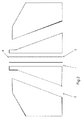
- shows one embodiment of the nozzle according to the invention as a diagrammatic cross-sectional view of the nozzle head area,
- Figure 3
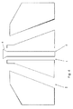
- shows another embodiment of the nozzle according to the invention as a diagrammatic cross-sectional view of the nozzle head area,
- Figure 4
- shows a further embodiment of the nozzle according to the invention as a diagrammatic cross-sectional view of the nozzle head area, and
- Figure 5
- shows yet another embodiment of the nozzle according to the invention as a diagrammatic cross-sectional view of the nozzle head area.
-
Figure 1 shows a prior art moistening nozzle as disclosed inUS 7820011 . The nozzle has a frame 1 and awater nozzle 2 connected to the inside of the frame 1 with a threadedjoint 17. Inside the frame 1 is also arranged anair nozzle 3 such that thewater nozzle 2 and theair nozzle 3 are concentric. Theair nozzle 3 is secured to the frame 1 with asecuring nut 4 which is connected to the exterior of the frame 1 with a threadedjoint 18. Thewater nozzle 2 includes a water connector 5 to which water is fed through a pipe or a hose or the like. From the water connector 5, the water flows out of the water nozzle through a water duct 6. In the frame 1 is also arranged an air connector 7 to which a pipe or a hose or the like is connected for feeding air to the moistening nozzle. Water is fed into the moistening nozzle, i.e., into the middle of the moistening nozzle, from the rear part thereof, and air is fed into the moistening nozzle from the side of the moistening nozzle. Air is conducted from the air connector 7 to an air chamber 8 arranged around ashaft 14 of the water nozzle. From the air chamber 8, the air flows axially towards theair nozzle 3 through apertures 9 in the frame 1. Theair nozzle 3 comprises aninternal thread 10 which is provided on the inner surface of theair nozzle 3 and by means of which the air is brought into swirling motion. The air in swirling motion thus flows through an air gap 19 in the moistening nozzle to surround the water supplied from thewater nozzle 2, whereby the mixture of water and air forms water mist. Due to the swirling motion, the water mist forms an even cone-shaped spray. Theair nozzle 3 is arranged inside the frame 1 in such a way that the air nozzle is positioned in place against acontrol surface 11 of the air nozzle inside the frame 1. Thecontrol surface 11 of the air nozzle is located around the central axis in the circumferential direction. Thewater nozzle 2, in turn, is positioned in place against afirst control surface 12 of the water nozzle provided on the inner surface of the frame 1. On theshaft 14 of thewater nozzle 2 may be provided acollar 13 by which thewater nozzle 2 is supported against thefirst control surface 12 of the water nozzle. Thefirst control surface 12 of the water nozzle is also parallel to the circumference around the axis of the moistening nozzle. Due to this structure, thecontrol surface 11 of the air nozzle and thefirst control surface 12 of the water nozzle can be provided with one attachment of a machining piece on the frame 1, whereby they can be made concentric with close tolerance and theair nozzle 3 and thewater nozzle 2 can be mutually centered with very good accuracy. In the frame 1 of the moistening nozzle are provided second andthird control surfaces - In the embodiment according to
Figure 2 , the nozzle comprises a first flow channel 1 for the fluid to be dispersed and surrounding it asecond flow channel 2 for the dispersing fluid, e.g. air or other gas. Theflow channel 2 is designed into a ring channel tapering towards the mouth, to which channel the dispersing fluid is supplied tangentially, thus bringing it into swirling motion. The swirling motion of the dispersing fluid can also be achieved in a different manner, for example, by mounting a separate spiral part in the second flow channel. The second flow channel does not have to be a tapering one, that is, conical, but it may be, for example, cylindrical. In the first flow channel 1 is mounted a closedcylindrical displacement part 3, by means of which the liquid to be dispersed discharges from the end of the flow channel as an annular flow, in the centre of which is a hollow space. Thedisplacement part 3 can extend slightly outwards from the flow channel 1, e.g. by a few millimeters, as can be seen inFigs. 3 and4 . - The embodiment of
Figure 3 differs from the embodiment ofFigure 2 only in that theend 4 of thedisplacement part 3 is formed into the shape of a tulip. In this case, the dispersing gas collides with the fluid to be dispersed at a relatively gently sloping angle. - In the embodiment of
Figure 4 , theend 4 of thedisplacement part 3 is designed to widen outwards in such a way that the fluid to be dispersed turns outwards, the dispersing fluid being arranged to collide with the fluid to be dispersed essentially in the outwards widening area of the displacement part. In this case, the angle of incidence between the dispersing fluid and the fluid to be dispersed is almost perpendicular. - In the embodiment of
Figure 5 , the dispersing capacity has been further increased by forming a third flow channel 5 in the displacement part, through which dispersing gas is fed into the hollow interior of the fluid to be dispersed. - In the following is described an example of the dimensioning of the displacement part.
- The diameter of the liquid channel without the displacement part is 5 mm, its cross-sectional are then being 19.6 mm2 and dispersing thickness 2.5 (half of the diameter). The droplet-forming area is the length of the circumference of the liquid column, that is, 15.7 mm. When using a displacement part, the corresponding nozzle is made by increasing the diameter of the liquid channel by less than a millimeter, that is, its outer diameter is 5.83 mm. In the centre is placed a displacement part with a diameter of 3mm. In this way, the cross-sectional area of the flow of the fluid remains the same as in the above case, that is, 19.6 mm2. The rate of flow of the liquid does not increase, but the dispersing thickness is now only 1.415 mm (decreasing almost to a half) and the droplet-forming area, that is, the length of the periphery is 18.3 mm (increasing by 17%). In tests carried out with the nozzles according to the invention were obtained the flow results shown in Table 1.
- In Table 1 is shown with two different dispersing air feed pressures (0.5 and 1.0 bar) the maximum rate of liquid flow which can be sprayed from the nozzle in such a way that the liquid to be dispersed still disperses efficiently into droplets. If the rate of liquid flow is increased from the maximum rate of flow given in the table, all of the liquid will no longer disperse as efficiently, but some of it will continue to travel as large drops/as a continuous liquid jet.
- The results shown in the table apply to a particular fluid used in this test and the absolute maximum flow values change when the properties of the fluid are changed. However, the table shows the advantage brought by the displacement part to the spraying capacity of the nozzle.
- The tested fibrous fluid had a dry matter content of about 4.5 % with the following composition:
- TMP pulp
- fractionated fine matter 60 %
- filler material 40 %
- Ansilex 93 (Calsinated clay pigment) 50 %
- Hydrocarbon 90 (Calsium carbonate pigment) 50 %
- The measured Brookfield 100 viscosity of the fibrous fluid was 520 mPas at a temperature of 12 °C.
Table 1 Nozzle without displacement part Nozzle with displacement part Dispersing air pressure bar Maximum flow from nozzle l/min Maximum flow from nozzle l/min 0.5 0.36 0.42 1.0 0.58 0.83 - The displacement part can also be used as a dispersing gas inlet channel by forming a third flow channel in its centre. The dispersing gas is led to the outer surface of the liquid column as before, but dispersing gas is in addition led inside the liquid through the displacement part.
- Both the displacement part by itself, and especially if additional dispersing gas is led through it, increase the dispersing capacity of the nozzle significantly. By means of one nozzle, larger amounts of liquid than presently can be applied and efficiently formed into droplets. Liquids which are difficult to disperse (nanocellulose, fibrous suspensions, etc.) are better to apply with an efficiently dispersing nozzle. The arrangement according to the invention saves energy, because the velocity of the dispersing gas, and thereby the feed pressure, do not have to be as high as in current nozzles.
Claims (6)
- A spray nozzle for supplying fluid intended for the manufacture and/or processing of a fibrous web in a paper or board machine in droplets into and/or onto the fibrous web, the nozzle comprising a first flow channel (1) for the fluid to be dispersed and a second flow channel (2) for the dispersing fluid, the second flow channel (2) surrounding the first flow channel (1), wherein the fluid to be dispersed exiting from the first flow channel (1) is arranged to travel essentially rectilinearly and the dispersing fluid exiting from the second flow channel (2) is arranged to travel in a swirling motion around the fluid to be dispersed and to come into contact with the fluid to be dispersed for dispersing it into droplets, characterized in that in the first flow channel is arranged, in its central area, a displacement part making the first flow channel (1) to surround the displacement part, whereby the fluid to be dispersed is discharged from the nozzle in the shape of a hollow body.
- A nozzle as claimed in claim 1, characterized in that the first channel is annular and the hollow body of the fluid discharged from the nozzle is in the form of hollow cylinder or cone, the cone being convergent or expanding.
- A nozzle as claimed in claim 1 or 2, characterized in that the end (4) of the displacement part (3) is designed to widen outwards in such a way that the fluid to be dispersed turns outwards, the dispersing fluid being arranged to collide with the fluid to be dispersed essentially in the outwards widening area of the displacement part (3).
- A nozzle as claimed in any of claims 1 to 3, characterized in that in the centre of the displacement part (3) is formed a third flow channel (5) for feeding additional dispersing fluid into the hollow interior of the fluid flow to be dispersed.
- The use of a nozzle as claimed in any of the claims 1 to 4 for dispersing highly viscous fluid.
- The use of claim 5 for dispersing fibrous fluid.
Priority Applications (1)
| Application Number | Priority Date | Filing Date | Title |
|---|---|---|---|
| EP13196449.6A EP2883617A1 (en) | 2013-12-10 | 2013-12-10 | Dispersing nozzle for supplying fluid intended for the manufacture and/or processing of a fibrous web in a paper or board machine in droplets into and/or onto the fibrous web |
Applications Claiming Priority (1)
| Application Number | Priority Date | Filing Date | Title |
|---|---|---|---|
| EP13196449.6A EP2883617A1 (en) | 2013-12-10 | 2013-12-10 | Dispersing nozzle for supplying fluid intended for the manufacture and/or processing of a fibrous web in a paper or board machine in droplets into and/or onto the fibrous web |
Publications (1)
| Publication Number | Publication Date |
|---|---|
| EP2883617A1 true EP2883617A1 (en) | 2015-06-17 |
Family
ID=49880385
Family Applications (1)
| Application Number | Title | Priority Date | Filing Date |
|---|---|---|---|
| EP13196449.6A Withdrawn EP2883617A1 (en) | 2013-12-10 | 2013-12-10 | Dispersing nozzle for supplying fluid intended for the manufacture and/or processing of a fibrous web in a paper or board machine in droplets into and/or onto the fibrous web |
Country Status (1)
| Country | Link |
|---|---|
| EP (1) | EP2883617A1 (en) |
Citations (10)
| Publication number | Priority date | Publication date | Assignee | Title |
|---|---|---|---|---|
| FR2098501A5 (en) * | 1970-06-09 | 1972-03-10 | Tunzini Sames | |
| FR2115663A5 (en) * | 1970-11-27 | 1972-07-07 | Tunzini Sames | |
| GB1321468A (en) * | 1969-09-26 | 1973-06-27 | Tunzini Ameliorair Sa | Atomisation nozzle |
| US20020175225A1 (en) * | 1999-12-20 | 2002-11-28 | Carlisle Friesland B. V. | Devic for atomizing a liquid product, a spray-drying and conditioning device provided therewith, and a method for conditioning a liquid product |
| US20050023376A1 (en) * | 2002-06-06 | 2005-02-03 | Anderson Steven R. | Air atomizing assembly and method and system of applying an air atomized material |
| JP2005288390A (en) * | 2004-04-02 | 2005-10-20 | Kyoritsu Gokin Co Ltd | Two-fluid nozzle and spraying method |
| US6969012B2 (en) | 2002-01-24 | 2005-11-29 | Kangas Martti Y O | Low pressure atomizer for difficult to disperse solutions |
| DE102005002392A1 (en) * | 2005-01-19 | 2006-07-27 | Pfalz, Thomas, Dipl.-Ing. | Mixing and spraying method e.g. for treatment agents and for rapid generation of persistent aerosol, involves bringing treatment mix into first mixer having air flow and distributed in transverse direction |
| US7820011B2 (en) | 2004-07-30 | 2010-10-26 | Metso Automation Oy | Moistening nozzle of a paper web |
| DE102011120717A1 (en) * | 2011-12-12 | 2013-06-13 | Sm-Klebetechnik Vertriebs Gmbh | Fluid nozzle for application of highly viscous materials e.g. high viscosity adhesive, has deflector metal sheet such as lock washer provided in gas outlet which is arranged around substance outlet |
-
2013
- 2013-12-10 EP EP13196449.6A patent/EP2883617A1/en not_active Withdrawn
Patent Citations (10)
| Publication number | Priority date | Publication date | Assignee | Title |
|---|---|---|---|---|
| GB1321468A (en) * | 1969-09-26 | 1973-06-27 | Tunzini Ameliorair Sa | Atomisation nozzle |
| FR2098501A5 (en) * | 1970-06-09 | 1972-03-10 | Tunzini Sames | |
| FR2115663A5 (en) * | 1970-11-27 | 1972-07-07 | Tunzini Sames | |
| US20020175225A1 (en) * | 1999-12-20 | 2002-11-28 | Carlisle Friesland B. V. | Devic for atomizing a liquid product, a spray-drying and conditioning device provided therewith, and a method for conditioning a liquid product |
| US6969012B2 (en) | 2002-01-24 | 2005-11-29 | Kangas Martti Y O | Low pressure atomizer for difficult to disperse solutions |
| US20050023376A1 (en) * | 2002-06-06 | 2005-02-03 | Anderson Steven R. | Air atomizing assembly and method and system of applying an air atomized material |
| JP2005288390A (en) * | 2004-04-02 | 2005-10-20 | Kyoritsu Gokin Co Ltd | Two-fluid nozzle and spraying method |
| US7820011B2 (en) | 2004-07-30 | 2010-10-26 | Metso Automation Oy | Moistening nozzle of a paper web |
| DE102005002392A1 (en) * | 2005-01-19 | 2006-07-27 | Pfalz, Thomas, Dipl.-Ing. | Mixing and spraying method e.g. for treatment agents and for rapid generation of persistent aerosol, involves bringing treatment mix into first mixer having air flow and distributed in transverse direction |
| DE102011120717A1 (en) * | 2011-12-12 | 2013-06-13 | Sm-Klebetechnik Vertriebs Gmbh | Fluid nozzle for application of highly viscous materials e.g. high viscosity adhesive, has deflector metal sheet such as lock washer provided in gas outlet which is arranged around substance outlet |
Similar Documents
| Publication | Publication Date | Title |
|---|---|---|
| CA2797990C (en) | Non-cylindrical-shaped openings into nozzle head | |
| CN104540597B (en) | Full cone air-assisted injection nozzle assembly | |
| US11141747B2 (en) | Nozzle arrangement for a spray gun | |
| US10052647B2 (en) | Nozzle assembly with self-cleaning face | |
| CN209735001U (en) | Spray nozzle for spray dryer | |
| RU2445547C1 (en) | Kochetov's radial-flow sprayer | |
| CN102091678B (en) | Airflow atomizer | |
| CN100574895C (en) | Two-material atomizing device | |
| EP2883617A1 (en) | Dispersing nozzle for supplying fluid intended for the manufacture and/or processing of a fibrous web in a paper or board machine in droplets into and/or onto the fibrous web | |
| CN101890399A (en) | Spray nozzle | |
| EP2808087B1 (en) | Device for treating a fibre web | |
| RU2513403C1 (en) | Disc-type sprinkler | |
| RU2460589C1 (en) | Disc-type sprayer | |
| CN202052655U (en) | Air flow type atomization device | |
| CN103752431A (en) | Modularization multi-thread micro-jetting atomizer | |
| EP2757193A1 (en) | Spray nozzle and a method for spraying fluids in droplets for processing fibrous webs | |
| CN114602675B (en) | A Noise Reduction Nozzle with Split Flow Structure | |
| RU2641281C1 (en) | Centrifugal vortex nozzle | |
| FI131101B1 (en) | Nozzle | |
| RU2670830C9 (en) | Pneumatic spray nozzle for spraying liquids | |
| CN207138146U (en) | High viscosity fluid nozzle | |
| CN206286089U (en) | A kind of secondary-atomizing formula atomizer | |
| RU2341336C1 (en) | Atomiser | |
| RU2311964C1 (en) | Liquid sprayer | |
| RU2597608C1 (en) | Fluid sprayer |
Legal Events
| Date | Code | Title | Description |
|---|---|---|---|
| PUAI | Public reference made under article 153(3) epc to a published international application that has entered the european phase |
Free format text: ORIGINAL CODE: 0009012 |
|
| 17P | Request for examination filed |
Effective date: 20131210 |
|
| AK | Designated contracting states |
Kind code of ref document: A1 Designated state(s): AL AT BE BG CH CY CZ DE DK EE ES FI FR GB GR HR HU IE IS IT LI LT LU LV MC MK MT NL NO PL PT RO RS SE SI SK SM TR |
|
| AX | Request for extension of the european patent |
Extension state: BA ME |
|
| STAA | Information on the status of an ep patent application or granted ep patent |
Free format text: STATUS: THE APPLICATION IS DEEMED TO BE WITHDRAWN |
|
| 18D | Application deemed to be withdrawn |
Effective date: 20151218 |