EP2883509A1 - Ultrasonic probe and method for producing ultrasonic probe - Google Patents
Ultrasonic probe and method for producing ultrasonic probe Download PDFInfo
- Publication number
- EP2883509A1 EP2883509A1 EP13828660.4A EP13828660A EP2883509A1 EP 2883509 A1 EP2883509 A1 EP 2883509A1 EP 13828660 A EP13828660 A EP 13828660A EP 2883509 A1 EP2883509 A1 EP 2883509A1
- Authority
- EP
- European Patent Office
- Prior art keywords
- area
- distal end
- ultrasonic probe
- gravity
- center axis
- Prior art date
- Legal status (The legal status is an assumption and is not a legal conclusion. Google has not performed a legal analysis and makes no representation as to the accuracy of the status listed.)
- Withdrawn
Links
Images





Classifications
-
- A—HUMAN NECESSITIES
- A61—MEDICAL OR VETERINARY SCIENCE; HYGIENE
- A61B—DIAGNOSIS; SURGERY; IDENTIFICATION
- A61B17/00—Surgical instruments, devices or methods
- A61B17/32—Surgical cutting instruments
- A61B17/320068—Surgical cutting instruments using mechanical vibrations, e.g. ultrasonic
-
- A—HUMAN NECESSITIES
- A61—MEDICAL OR VETERINARY SCIENCE; HYGIENE
- A61B—DIAGNOSIS; SURGERY; IDENTIFICATION
- A61B17/00—Surgical instruments, devices or methods
- A61B2017/00526—Methods of manufacturing
-
- A—HUMAN NECESSITIES
- A61—MEDICAL OR VETERINARY SCIENCE; HYGIENE
- A61B—DIAGNOSIS; SURGERY; IDENTIFICATION
- A61B17/00—Surgical instruments, devices or methods
- A61B17/32—Surgical cutting instruments
- A61B17/320068—Surgical cutting instruments using mechanical vibrations, e.g. ultrasonic
- A61B2017/320072—Working tips with special features, e.g. extending parts
- A61B2017/320073—Working tips with special features, e.g. extending parts probe
-
- A—HUMAN NECESSITIES
- A61—MEDICAL OR VETERINARY SCIENCE; HYGIENE
- A61B—DIAGNOSIS; SURGERY; IDENTIFICATION
- A61B17/00—Surgical instruments, devices or methods
- A61B17/32—Surgical cutting instruments
- A61B17/320068—Surgical cutting instruments using mechanical vibrations, e.g. ultrasonic
- A61B2017/320072—Working tips with special features, e.g. extending parts
- A61B2017/320078—Tissue manipulating surface
-
- A—HUMAN NECESSITIES
- A61—MEDICAL OR VETERINARY SCIENCE; HYGIENE
- A61B—DIAGNOSIS; SURGERY; IDENTIFICATION
- A61B17/00—Surgical instruments, devices or methods
- A61B17/32—Surgical cutting instruments
- A61B17/320068—Surgical cutting instruments using mechanical vibrations, e.g. ultrasonic
- A61B2017/320082—Surgical cutting instruments using mechanical vibrations, e.g. ultrasonic for incising tissue
-
- A—HUMAN NECESSITIES
- A61—MEDICAL OR VETERINARY SCIENCE; HYGIENE
- A61B—DIAGNOSIS; SURGERY; IDENTIFICATION
- A61B17/00—Surgical instruments, devices or methods
- A61B17/32—Surgical cutting instruments
- A61B17/320068—Surgical cutting instruments using mechanical vibrations, e.g. ultrasonic
- A61B2017/320088—Surgical cutting instruments using mechanical vibrations, e.g. ultrasonic with acoustic insulation, e.g. elements for damping vibrations between horn and surrounding sheath
-
- A—HUMAN NECESSITIES
- A61—MEDICAL OR VETERINARY SCIENCE; HYGIENE
- A61B—DIAGNOSIS; SURGERY; IDENTIFICATION
- A61B17/00—Surgical instruments, devices or methods
- A61B17/32—Surgical cutting instruments
- A61B17/320068—Surgical cutting instruments using mechanical vibrations, e.g. ultrasonic
- A61B2017/320089—Surgical cutting instruments using mechanical vibrations, e.g. ultrasonic node location
-
- Y—GENERAL TAGGING OF NEW TECHNOLOGICAL DEVELOPMENTS; GENERAL TAGGING OF CROSS-SECTIONAL TECHNOLOGIES SPANNING OVER SEVERAL SECTIONS OF THE IPC; TECHNICAL SUBJECTS COVERED BY FORMER USPC CROSS-REFERENCE ART COLLECTIONS [XRACs] AND DIGESTS
- Y10—TECHNICAL SUBJECTS COVERED BY FORMER USPC
- Y10T—TECHNICAL SUBJECTS COVERED BY FORMER US CLASSIFICATION
- Y10T29/00—Metal working
- Y10T29/49—Method of mechanical manufacture
- Y10T29/49002—Electrical device making
- Y10T29/49005—Acoustic transducer
Definitions
- the present invention relates to an ultrasonic probe which is configured to transmit longitudinal vibration parallel to a longitudinal axis as a result of transmittance of ultrasonic vibration, and a manufacturing method of the ultrasonic probe.
- WO2010/047395A1 discloses a treatment device with a treatment section located at a distal end portion of an ultrasonic probe and shaped like a hook.
- the treatment device generates ultrasonic vibration with the treatment section hooked to a biological tissue. Pulling the treatment section toward an operator allows the biological tissue to be treated.
- the treatment device keeps the whole probe in balance based on the shape of the treatment section.
- a distal end hook section is formed on an upper surface side of the treatment section disposed at the distal end of a probe main body section, and a recess portion is formed on a lower surface side of the treatment section.
- the treatment section is appropriately forme4d as described above so that the center of gravity of the treatment section coincides with the center of gravity of the probe main body section, thus stabilizing vibration.
- the treatment tool in WO2010/047395A1 includes the leading end hook section formed on the upper surface side of the treatment section and the recess portion formed on the lower surface side of the treatment section so that the center of gravity of the treatment section coincides with the center of gravity of the probe main body section of the ultrasonic probe.
- the shape of the treatment section has only a low degree of freedom, and for example, it may be difficult to appropriately form the treatment section so that the treatment section conforms to the biological tissue to be treated. Therefore, an ultrasonic probe is desired which allows the treatment section to be appropriately shaped while being formed so that the center of gravity of the treatment section coincides with the center of gravity of the probe main body section, in order to stabilize vibration.
- It is an object of the present invention is to provide an ultrasonic probe which allows a treatment section to be appropriately shaped while stabilizing vibration and which can be inexpensively manufactured, and to provide a method for manufacturing the ultrasonic probe.
- an ultrasonic probe configured to transmit a longitudinal vibration of an ultrasonic vibration along a longitudinal axis defined by a proximal end and a distal end thereof from the proximal end toward the distal end, includes: a first area including a proximal end portion, a distal end portion and a center axis which is defined by the proximal end portion and the distal end portion and which is parallel to the longitudinal axis, the first area having an antinode position of the ultrasonic vibration at the distal end portion; a treatment section located on a distal end side with respect to the distal end portion of the first area and having a center of gravity at a position displaced from the center axis of the first area; and a second area located between the distal end portion of the first area and the treatment section so as to be continuous with the distal end portion of the first area and configured to have a gravity center axis positioned parallel to the center axis of the first area so as to pass through the center of gravity of the
- Another aspect of a manufacturing method of an ultrasonic probe with a proximal end and a distal end includes: producing a first area adjacent to the proximal end of the ultrasonic probe to define a center axis of the first area, while leaving a site of a preparation body corresponding to a treatment section of the ultrasonic probe unprocessed, out of the preparation body that is long along a longitudinal axis defined by the proximal end and the distal end; machining the site corresponding to the treatment section and located at a distal end of the ultrasonic probe to define a center of gravity of the treatment section located at the distal end of the ultrasonic probe, at a position displaced from the center axis of the first area; and machining a second area between the first area and the treatment section in such a manner that a center of gravity of the second area is positioned parallel to the center axis of the first area so as to pass through the center of gravity of the treatment section.
- FIGS. 1 to 9B An embodiment of the present invention including variations thereof will be described with reference to FIGS. 1 to 9B .
- an ultrasonic treatment system 10 includes a power supply unit 12 and an ultrasonic treatment unit 14 serving as an ultrasonic treatment device.
- the ultrasonic treatment unit 14 includes an ultrasonic vibration generating unit 16 and an ultrasonic probe unit 18.
- the power supply unit 12 includes an electrical current supply section 22 that supplies electrical current to the ultrasonic vibration generating unit 16 and an input section 24.
- the input section 24 is connected to, for example, a foot switch (not shown in the drawings) to enable switching between a state where the electrical current supply section 22 supplies electrical current and a state where the supply of electrical current is stopped.
- a foot switch not shown in the drawings
- an ultrasonic transducer 34 described below can be vibrated at an appropriate amplitude based on an operational state of the foot switch.
- the ultrasonic vibration generating unit 16 includes a transducer case 32 serving as an outer shell, an ultrasonic transducer 34 located inside the transducer case 32 and serving as a vibration generating unit, and a cable 36 extending from a proximal end of the transducer case 32 and detachably connected to the power supply unit 12.
- the transducer case 32 is formed of, for example, an insulating resin material.
- the ultrasonic transducer 34 is, for example, of a BLT type. Electric wires 38a and 38b are connected to the ultrasonic transducer 34 at one end of each electric wire. The electric wires 38a and 38b pass through the cable 36 and are connected to the electrical current supply section 22 of the power supply unit 12 at the other end of each electric wire. The electrical current supply section 22 supplies electrical current to the ultrasonic transducer 34 via the electric wires 38a and 38b in the cable 36. Thus, the ultrasonic transducer 34 generates ultrasonic vibration.
- a horn 40 is coupled to a distal end direction side of the ultrasonic transducer 34 to increase the amplitude of ultrasonic vibration. The horn 40 is attached to, for example, the transducer case 32. Furthermore, an internal thread portion 42 is formed at a distal end portion of the horn 40.
- the ultrasonic probe unit 18 includes an ultrasonic probe 52 and a sheath 54.
- the sheath 54 is formed of an electrically insulating resin material or the like.
- the sheath 54 is formed to cover the entire outer peripheral surface of a first area 72 and a second area 74 of the ultrasonic probe 52, both of which will be described below, and to expose a treatment area 64 from a distal end 54a of the sheath 54.
- a proximal end 54b of the sheath 54 is detachably fixed to the transducer case 32.
- a ring 56 formed of, for example, a rubber material having insulating properties, is disposed between the ultrasonic probe 52 and the sheath 54 at a vibration node position.
- the ring 56 is preferably disposed at each of the vibration node positions.
- an annular recess portion is also preferably formed at the position where the ring 56 is disposed (vibration node position).
- the sheath 54 and the ring 56 according to the embodiment may be unwanted depending on a usage state of the ultrasonic treatment unit 14.
- the ultrasonic probe 52 shown in FIG. 3A is formed of, for example, a titanium alloy.
- the ultrasonic probe 52 includes a probe main body section 62 and a treatment area (treatment section) 64 provided closer to a distal end of the ultrasonic probe 52 than the probe main body section 62 to treat a biological tissue.
- the probe main body section 62 includes an external thread portion 66 on an outer peripheral portion of a proximal end of the probe main body section 62.
- the external thread portion 66 engages, in a threaded manner, with the internal thread portion 42 formed on the horn 40 as shown in FIG. 2 .
- the ultrasonic probe 52 is attached to the ultrasonic vibration generating unit 16.
- the ultrasonic probe 52 attached to the ultrasonic vibration generating unit 16 allows ultrasonic vibration generated by the ultrasonic transducer 34 to be transmitted to the ultrasonic probe 52.
- the ultrasonic vibration transmitted to the ultrasonic probe 52 enables the ultrasonic probe 52 to generate longitudinal vibration that is parallel to a center axis C in the direction of vibration and in the direction of transmission.
- the probe main body section 62 extends in a longitudinal direction along the center axis C.
- the probe main body section 62 includes the first area 72 located on a proximal end side of the probe main body section 62 in a longitudinal direction thereof and including the external thread portion 66 formed at a most proximal end and the second area 74 provided on a distal end direction side of the first region 72.
- the first area 72 is formed to be straight, and all transverse sections are the same in size and shape.
- the second area 74 is preferably formed to be straight, and all transverse sections are the same in size and shape.
- the second area 74 includes a treatment area 64 on a distal end direction side of the second region 74.
- both the first area 72 and the second area 74 may be tapered so that transverse sections on the proximal end side are formed to be larger than cross sections on the distal end side.
- the first area 72 shown in FIG. 3A and FIG. 3B is formed to be, for example, cylindrical.
- the center axis C coincides with the center of gravity (gravity center axis) at the position of each transverse section orthogonal to the center axis C. That is, at any position between the distal end and the proximal end of the first area 72, the center axis C coincides with the center of gravity on a transverse section orthogonal to the center axis C.
- the center of gravity on each circular transverse section orthogonal to the longitudinal direction of the first area 72 corresponds to the center of the transverse section.
- the center axis C is defined by a set of centers of gravity on the respective cross sections between a distal end portion 73a and a proximal end portion 73b of the first area 72.
- a boundary between the first area 72 and the second area 74 is adjusted to correspond to an antinode position of vibration.
- a drive frequency is 47kHz and the ultrasonic probe 52 is formed of 6-4Ti and has an outer diameter of approximately 6mm
- a half-wavelength is approximately 51mm to approximately 52mm.
- the length from a distal end of the ultrasonic transducer 34 (a proximal end of the horn 40) to the distal end portion 73a of the first area 72 of the probe main body section 62 is 51mm to 52mm x n (n: an integer of one or larger).
- the length from the distal end of the ultrasonic transducer 34 (the proximal end of the horn 40) to the distal end portion 73a of the first area 72 of the probe main body section 62 is an integral multiple of the half-wavelength (n times as large as the half-wavelength).
- the total length of the second area 74 and the treatment area 64 is preferably an integral multiple of the half-wavelength (n times as large as the half-wavelength).
- the half-wavelength is approximately 102mm to approximately 104mm.
- the length from the distal end of the ultrasonic transducer 34 (the proximal end of the horn 40) to the distal end portion 73a of the first area 72 of the probe main body section 62 is an integral multiple of, for example, 102mm to 104mm.
- the total length of the second area 74 and the treatment area 64 is an integral multiple of, for example, 102mm to 104mm.
- the treatment region 64 shown in FIG. 3A is bent relative to the distal end portion 75a of the second area 74 of the probe main body section 62.
- the treatment area 64 is shaped like a hook.
- the center of gravity is displaced to a position shown by reference symbol GO in FIG. 3A relative to the center axis C of the first area 72.
- the center of gravity G0 of the treatment area 64 in FIG. 3A is displaced toward an upper side of FIG. 3A and FIG. 3B relative to the center axis C.
- a set of centers of gravity on transverse sections in the second area 74 which are orthogonal to the center axis C of the first area 72 is linear as shown by reference symbol G in FIG. 3A and FIG. 3B .
- the straight line shown by reference symbol G is parallel to the center axis C of the first area 72, but is not the same as and is positioned differently from the center axis C.
- the treatment area 64 is formed as shown in FIG. 3A and the center of gravity G0 of the treatment area 64 is displaced upward from the center axis C in FIG. 3A and FIG.
- the second area 74 is formed by machining such that the straight line G, a set of centers of gravity on transverse sections orthogonal to the center axis C of the first area 72, passes through the barycenter G0 of the treatment area 64, or closer to the center of gravity G0 than the center axis C. That is, the straight line G (center axis) passing through the center of gravity of the second area 74 is parallel to the center axis C, passing through the center of gravity of the first area, and is not the same as and is positioned differently from the center axis C. In other words, the center axis of the second area (straight line G) is parallel to the center axis C of the first area and passes through the center of gravity G0, or closer to the center of gravity G0 than the center axis C.
- the center of gravity G is isolated at the boundary between the first area 72 and the second area 74, and the boundary position corresponds to the antinode position of the vibration.
- the antinode position of the vibration is displaced more significantly than the other positions.
- the state of a medium near the antinode position of the vibration remains unchanged, resulting in no stress, as is the case where no wave is generated.
- no or substantially no adverse effect is exerted on the vibration.
- the center of gravity lies on a straight line parallel to the center axis C and is constant over every half-wavelength. This allows longitudinal vibration to be stabilized.
- a procedure for manufacturing (method for manufacturing) the ultrasonic probe 52 will be described with reference to FIG. 4A to FIG. 4E .
- the treatment area 64 is shaped like a hook as shown in FIG. 3A .
- a rod-like member (preparation body) which is formed of, for example, a titanium alloy material (preparation body) 52a and which is long and straight along a longitudinal direction (longitudinal axis) L.
- An outer peripheral surface of a transverse section orthogonal to the longitudinal direction of the rod-like member 52a may be, for example, circular or polygonal.
- the length of the rod-like member 52a is determined by the resonant frequency of the ultrasonic transducer 34 used, the length of the connected horn 40, a target biological tissue to be treated, and the like.
- the outer peripheral surface of a transverse section of the rod-like member 52a is not circular, the outer peripheral surface of the rod-like member 52a is preferably machined to be circular using a lathe or the like.
- the maximum outer diameter of the rod-like member 52a is appropriately determined based on, for example, the inner diameter (for example, 5mm, 10mm, 12mm, or the like) of a trocar inserted into a body cavity, though the maximum outer diameter depends on whether or not the sheath 54 is arranged on the outer periphery of the ultrasonic probe 52 and the thickness of the sheath 54.
- the rod-like member 52a shown in FIG. 4A is placed on a lathe, and the outer peripheral surface of a site 72a of the first area 72 is machined so as to be shaped like the first area 72 as shown in FIG. 4B .
- the outer peripheral surface of a site 74a corresponding to the second area 74 is also preferably machined so as to have an outer diameter similar to the outer diameter of the first area 72.
- a cylindrical portion 64a forming the treatment area 64 is left on a distal end direction side of the site 74a corresponding to the second area 74.
- the first area 72 is formed.
- a site 66a corresponding to the external thread portion 66 may be formed at this stage or after the treatment area 64 and the second area 74 are formed. Alternatively, the site 66a corresponding to the external thread portion 66 may be formed before the first area 72 is formed. Threads may subsequently be formed in the site 66a corresponding to the external thread portion 66 at any stage.
- the outer peripheral surface of the site 74a corresponding to the second area 74 is further machined so as to have a smaller outer diameter than the first area 72.
- the center of gravity on the first area 72 and the center of gravity on the site 74a corresponding to the second area 74 both still lie on the same center axis C of the first area 72.
- the site 64a corresponding to the treatment area 64 is appropriately machined using, for example, a five-axis NC lathe or forging, to produce a treatment area 64.
- the treatment area 64 is formed such that the range of the treatment area 64 relative to the center axis C does not exceed 2.5mm.
- the treatment area 64 is formed such that an upper side of the treatment area 64 relative to the center axis C in FIG. 4D is smaller than 2.5mm, and a lower side of the treatment area 64 relative to the center axis C in FIG.
- the thus-determined shape of the treatment area 64 determines the center of gravity G0 of the treatment area 64.
- the center of gravity G0 of the treatment area 64 lies above the center axis C in FIG. 4D .
- the center of gravity of the site 74a corresponding to the second area 74 lies on the same center axis C of the first area 72.
- the center of gravity G0 of the treatment area 64 is displaced from the center of gravity of the site 74a corresponding to the second area 74.
- the site 74a corresponding to the second area 74 is partly removed using, for example, a milling machine so that an imaginary straight line G passing and through the center of gravity G0 and parallel to the center axis C of the treatment area 64 provide a set of centers of gravity in the second area 74.
- the lower portion in FIG. 4D is partly removed flat to form a flat surface 76 shown in FIG. 3A , FIG. 3B , and FIG. 4E . That is, the barycenter G of the second area 74 is displaced upward, in FIG. 4E , relative to the center of gravity of the site 74a corresponding to the second area 74.
- the barycenter G0 of the treatment area 64 is consequently defined displaced from the center axis C of the first area 72.
- the second area 74 is machined from the distal end to the proximal end thereof so that the center of gravity of the second area 74 is positioned parallel to the center axis C so as to pass through the center of gravity G0 of the treatment area 64 or closer to the center of gravity G0 than the center axis C.
- the ultrasonic probe 52 can be produced such that the center of gravity (gravity center axis) G between the distal end and proximal end of the second area 74 is displaced parallel to the center axis C so as to coincide with the center of gravity G0 of the treatment area 64 or to be closer to the center of gravity G0 than the center axis C.
- the center of gravity gravitation center axis
- FIG. 5A corresponds to FIG. 4A
- FIG. 5B corresponds to FIG. 4B
- FIG. 5C corresponds to FIG. 4C .
- description of FIGS. 5A to 5C is omitted.
- the second area 74 is formed before the formation of the treatment area 64 based on machining, and the gravity center axis G of the second area 74 is defined at a position displaced from the center axis C of the first area 72. This is because the center of gravity G0 can be easily determined after the treatment area 64 is machined based on, for example, experience in forming a large number of ultrasonic probes 52 with the same shape and design.
- the second area 74 is formed, and the treatment area 64 is formed by machining to have a predetermined shape (a shape specified by design).
- the treatment area 64 can be formed so that the center of gravity G of the second area 74 passes through the center of gravity G0 of the treatment area 64, or be closer to the center of gravity G0 than the center axis C.
- the external thread portion 66 at the proximal end of the ultrasonic probe 52 is engaged with the internal thread portion 42 of the horn 40 in a threaded manner.
- a trocar (not shown in the drawings) is pierced into, for example, the abdominal cavity and fixed.
- the treatment area 64 of the ultrasonic probe unit 18 is guided, via the trocar, through the body cavity toward the biological tissue to be treated.
- the foot switch (not shown in the drawings) is operated to transmit a signal to the electrical current supply section 22 via the input section 24 to switch to the state where the electrical current supply section 22 supplies electrical current.
- the ultrasonic transducer 34 vibrates to transmit vibration to the ultrasonic probe 52 via the horn 40. That is, the ultrasonic probe 52 transmits longitudinal vibration resulting from ultrasonic vibration from the proximal end toward the distal end of the ultrasonic probe 52 along the longitudinal axis L defined by the proximal end and distal end.
- the center axis (center of gravity) C is straight from the proximal end of the horn 40 to the distal end portion 73a of the first area 72 of the ultrasonic probe 52 and is not displaced.
- the longitudinal vibration from the ultrasonic transducer 34 is stably transmitted through the horn 40 to the distal end portion 73a of the first area 72 without vibration loss.
- the center of gravity in the first area 72 and the center of gravity in the second area 74 are shifted from each other at the boundary between the distal end portion 73a of the first area 72 and the proximal end portion 75b of the second area 74.
- the boundary corresponds to the antinode position of the vibration and thus does not affect the vibration.
- the gravity center axis G is straight from the proximal end portion 75b to the distal end portion 75a of the second area 74 and is not displaced.
- the longitudinal vibration from the ultrasonic transducer 34 is stably transmitted through the horn 40 and the first area 72 to the distal end portion 75a of the second area 74 without vibration loss.
- the center of gravity GO of the treatment area 64 lies on an axis corresponding to an extension of the barycenter axis G of the second area 74. Consequently, the longitudinal vibration from the ultrasonic transducer 34 is stably transmitted through the horn 40, the first area 72, and the second area 74 to the distal end of the treatment area 64 without vibration loss.
- the ultrasonic vibration can be transmitted to the hooked biological tissue through the treatment area 64 with vibration loss minimized.
- pulling the treatment area 64 toward the operator allows the biological tissue to be appropriately treated, for example, incised.
- the center of gravity of the second area 74 may be correspondingly adjusted. This ensures an appropriate degree of freedom for the shape of the treatment area 64.
- the treatment area 64 is not limited to the hook shape shown in FIG. 3A , but the treatment area 64 shaped like a paddle as shown in FIGS. 6A to 6C , or like scissors as shown in FIG. 7 , may be suitably used.
- the center of gravity of the second area 74 is adjusted such that the center of gravity G defined by a set of centers of gravity on transverse sections in the second area 74 orthogonal to the center axis C of the first area 72 coincides with the center of gravity G0 of the treatment area 64, or is closer to the center of gravity G0 than the center axis C.
- stable longitudinal vibration can be transmitted to the first area 72, to the second area 74, and further to the treatment area 64.
- the longitudinal vibration can be prevented from being disturbed, or be made difficult to disturb, by setting the center of gravity of the ultrasonic probe 52 to be straight over a half-wavelength portion or an integral multiple thereof on the distal end side of the ultrasonic probe 52.
- the center of gravity of the first area 72 and the center of gravity of the second area 74 are displaced from each other at the boundary between the first area 72 and the second area 74, the center of gravity of the first area 72 lies on the center axis C, and the center of gravity in the second area 74 and the treatment area 64 lies on the straight line G which is parallel to the center axis C, the longitudinal vibration from the ultrasonic transducer 34 can be stably transmitted to the treatment area 64 via the ultrasonic probe 52.
- the longitudinal vibration can be made difficult to disturb simply by adjusting the center of gravity over a half-wavelength portion or an integral multiple thereof on the distal end side of the ultrasonic probe 52, undesirable vibration such as a transversal wave can be prevented from being generated, particularly in the probe main body section 62 of the ultrasonic probe 52, without an increase in machining costs.
- the step has been described in which the site 74a corresponding to the second area 74 is formed to have an outer diameter smaller than the outer diameter of the first area 72 as shown in FIG. 4C and FIG. 5C .
- this step may be omitted. That is, if the gravity center axis G can be displaced relative to the center axis C by machining the site 74a corresponding to the second area 74 to form, for example, the flat surface 76 as shown in FIG. 3C , then the diameter of the site 74a need not necessarily be reduced. Instead, the second area 74 may be formed to have a larger diameter.
- the second area 74 may be formed like a cylinder with a center axis displaced from the center axis C of the cylindrical first area 72 (that is, the second area 74 is made eccentric to the first area 72). That is, the second area 74 can also be formed to be cylindrical.
- the formation of the cylindrical second area 74 with a center of gravity displaced from the center of gravity of the first area 72 incurs higher machining costs than the formation in the example shown in FIGS. 4A to 4E or FIGS. 5A to 5E described above.
- both the cylindrical first and second areas 72 and 74 it is advantageous in terms of costs to set both the cylindrical first and second areas 72 and 74 to have the same center axis and then to adjust the center of gravity of the second area 74 by machining one surface (for example, a flat surface 76) of the second area 74.
- shaping the second area 74 as shown in FIGS. 8A to 8F is also suitable. Any of various well-known machine tools may be used to machine the second area 74 as shown in FIGS. 8A to 8F . Machined portions (removed surfaces) 76a, 76b, 76c, 76d, 76e, and 76f removed as shown in FIGS. 8A to 8F allow the center of gravity G to be displaced upward relative to the center C of an imaginary circle in each of the figures.
- the barycenter G can be displaced by forming an odd-shaped portion which is not circular and which fails to exhibit point symmetry with respect to the center axis C of the first area 72, for example, as shown by reference numerals 76, 76a, 76b, 76c, 76d, 76e, and 76f. Even in such cases as shown by reference numerals 76, 76a, 76b, 76c, 76d, and 76e, the ultrasonic probe 52 can be formed more inexpensively than in the case where the shape of the second area 74 is kept cylindrical.
- the first area 72 of the above-described ultrasonic probe 52 is formed to exhibit point symmetry with respect to the center axis C of the first area 72.
- the second area 74 is formed to exhibit asymmetry with respect to the gravity center axis G so that the gravity center axis G passes through the center of gravity G0 of the treatment area 64.
- the first area 72 is circular
- the outer peripheral surface of the second area 74 is partly shaped like a part of a circle.
- the first area is preferably shaped like a polygon with 2n sides (n: a natural number) such as a hexagon as shown by reference numeral 172 in FIG. 9A or like a polygon with 2n+1 sides (n: a natural number) such as a pentagon as shown by reference numeral 272 in FIG. 9B .
- a machined portion in this case, the flat surface 76
- a machined portion is preferably formed in the second area as shown by reference numeral 174 in FIG. 9A by machining and removing a part of a hexagon.
- a machined portion in this case, the flat surface 76
- the center of gravity of the first area 272 lies at a position where a perpendicular line of a midpoint of one side (first side) extended to a vertex (first vertex) opposite to the first side intersects a perpendicular line of a midpoint of another side (second side) extended to a vertex (second vertex) opposite to the second side.
- the first area and the second area are suitably formed by appropriately combining the hexagon shown in FIG. 9A with the pentagon shown in FIG. 9B . That is, the probe main body section 62 is suitably formed by, for example, shaping the first area 72 like a pentagon and shaping the second area 74 like a hexagon and removing and partly removed. Alternatively, the probe main body section 62 may be suitably formed by, for example, shaping the first area 72 like a hexagon and shaping the second area 74 like a pentagon and removing part of the shape by machining.
Landscapes
- Health & Medical Sciences (AREA)
- Engineering & Computer Science (AREA)
- Life Sciences & Earth Sciences (AREA)
- Surgery (AREA)
- General Health & Medical Sciences (AREA)
- Nuclear Medicine, Radiotherapy & Molecular Imaging (AREA)
- Biomedical Technology (AREA)
- Animal Behavior & Ethology (AREA)
- Public Health (AREA)
- Veterinary Medicine (AREA)
- Mechanical Engineering (AREA)
- Heart & Thoracic Surgery (AREA)
- Medical Informatics (AREA)
- Molecular Biology (AREA)
- Dentistry (AREA)
- Surgical Instruments (AREA)
- Radiology & Medical Imaging (AREA)
Abstract
Description
- The present invention relates to an ultrasonic probe which is configured to transmit longitudinal vibration parallel to a longitudinal axis as a result of transmittance of ultrasonic vibration, and a manufacturing method of the ultrasonic probe.
- For example,
WO2010/047395A1 discloses a treatment device with a treatment section located at a distal end portion of an ultrasonic probe and shaped like a hook. The treatment device generates ultrasonic vibration with the treatment section hooked to a biological tissue. Pulling the treatment section toward an operator allows the biological tissue to be treated. - The treatment device keeps the whole probe in balance based on the shape of the treatment section. Specifically, according to
WO2010/047395A1 , a distal end hook section is formed on an upper surface side of the treatment section disposed at the distal end of a probe main body section, and a recess portion is formed on a lower surface side of the treatment section. The treatment section is appropriately forme4d as described above so that the center of gravity of the treatment section coincides with the center of gravity of the probe main body section, thus stabilizing vibration. - As described above, the treatment tool in
WO2010/047395A1 includes the leading end hook section formed on the upper surface side of the treatment section and the recess portion formed on the lower surface side of the treatment section so that the center of gravity of the treatment section coincides with the center of gravity of the probe main body section of the ultrasonic probe. Thus, the shape of the treatment section has only a low degree of freedom, and for example, it may be difficult to appropriately form the treatment section so that the treatment section conforms to the biological tissue to be treated. Therefore, an ultrasonic probe is desired which allows the treatment section to be appropriately shaped while being formed so that the center of gravity of the treatment section coincides with the center of gravity of the probe main body section, in order to stabilize vibration. - It is an object of the present invention is to provide an ultrasonic probe which allows a treatment section to be appropriately shaped while stabilizing vibration and which can be inexpensively manufactured, and to provide a method for manufacturing the ultrasonic probe.
- One aspect of an ultrasonic probe configured to transmit a longitudinal vibration of an ultrasonic vibration along a longitudinal axis defined by a proximal end and a distal end thereof from the proximal end toward the distal end, includes: a first area including a proximal end portion, a distal end portion and a center axis which is defined by the proximal end portion and the distal end portion and which is parallel to the longitudinal axis, the first area having an antinode position of the ultrasonic vibration at the distal end portion; a treatment section located on a distal end side with respect to the distal end portion of the first area and having a center of gravity at a position displaced from the center axis of the first area; and a second area located between the distal end portion of the first area and the treatment section so as to be continuous with the distal end portion of the first area and configured to have a gravity center axis positioned parallel to the center axis of the first area so as to pass through the center of gravity of the treatment section or be closer to the center of gravity than the center axis, wherein the gravity center axis of the second area is displaced from the center axis of the first area at the distal end portion of the first area.
- Another aspect of a manufacturing method of an ultrasonic probe with a proximal end and a distal end, according to the present invention includes: producing a first area adjacent to the proximal end of the ultrasonic probe to define a center axis of the first area, while leaving a site of a preparation body corresponding to a treatment section of the ultrasonic probe unprocessed, out of the preparation body that is long along a longitudinal axis defined by the proximal end and the distal end; machining the site corresponding to the treatment section and located at a distal end of the ultrasonic probe to define a center of gravity of the treatment section located at the distal end of the ultrasonic probe, at a position displaced from the center axis of the first area; and machining a second area between the first area and the treatment section in such a manner that a center of gravity of the second area is positioned parallel to the center axis of the first area so as to pass through the center of gravity of the treatment section.
-
-
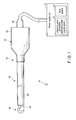
FIG. 1 is a schematic diagram showing an ultrasonic treatment system according to an embodiment of the present invention; -
FIG. 2 is a schematic vertical cross-sectional view showing a part of an ultrasonic vibration generating unit and an ultrasonic probe unit of the ultrasonic treatment system according to the embodiment of the present invention; -
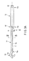
FIG. 3A is a schematic diagram showing an ultrasonic probe of the ultrasonic probe unit of the ultrasonic treatment system according to the embodiment of the present invention; -
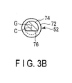
FIG. 3B is a schematic horizontal cross-sectional view of the ultrasonic probe of the ultrasonic probe unit of the ultrasonic treatment system according to the embodiment of the present invention, the cross-sectional view being taken along line 3B-3B inFIG. 3A ; -
FIG. 3C is a schematic diagram showing a variation of the ultrasonic probe of the ultrasonic probe unit of the ultrasonic treatment system according to the embodiment of the present invention; -
FIG. 4A is a schematic diagram showing a preparation body used to produce the ultrasonic probe of the ultrasonic probe unit of the ultrasonic treatment system according to the embodiment of the present invention; -
FIG. 4B is a schematic diagram showing that, in production of the ultrasonic probe of the ultrasonic probe unit of the ultrasonic treatment system according to the embodiment of the present invention, a site of the preparation body shown inFIG. 4A which corresponds to a first area and a second area of the probe main body section is machined to form the first area, and a site of the preparation body corresponding to a treatment area is left unprocessed; -
FIG. 4C is a schematic diagram showing that, in production of the ultrasonic probe of the ultrasonic probe unit of the ultrasonic treatment system according to the embodiment of the present invention, a site of the preparation body shown inFIG. 4B and corresponding to the second area of the probe main body section is machined, and a site of the preparation body shown inFIG. 4B and corresponding to the treatment area is left unprocessed; -
FIG. 4D is a schematic diagram showing that a site of the preparation body shown inFIG. 4C and corresponding to the treatment area is machined to form a hook-shaped treatment area; -
FIG. 4E is a schematic diagram showing that a site of the preparation body shown inFIG. 4D and corresponding to the second area is machined and partly removed to form the second area; -
FIG. 5A is a schematic diagram showing a preparation body used to produce the ultrasonic probe of the ultrasonic probe unit of the ultrasonic treatment system according to the embodiment of the present invention; -
FIG. 5B is a schematic diagram showing that, in production of the ultrasonic probe of the ultrasonic probe unit of the ultrasonic treatment system according to the embodiment of the present invention, a site of the preparation body shown inFIG. 5A which corresponds to the first area and the second area of the probe main body section is machined to form the first area, and a site of the preparation body corresponding to the treatment area is left unprocessed; -
FIG. 5C is a schematic diagram showing that, in production of the ultrasonic probe of the ultrasonic probe unit of the ultrasonic treatment system according to the embodiment of the present invention, a site of the preparation body shown inFIG. 5B and corresponding to the second area of the probe main body section is machined, and a site of the preparation body shown inFIG. 5B and corresponding to the treatment area is left unprocessed; -
FIG. 5D is a schematic diagram showing that a site of the preparation body shown inFIG. 5C and corresponding to the second area is machined to form the second area; -
FIG. 5E is a schematic diagram showing that a site of the preparation body shown inFIG. 5D and corresponding to the treatment area is machined to form a hook-shaped treatment area; -
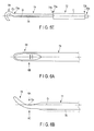
FIG. 6A is a schematic top view showing a spatulashaped treatment area in a variation of the ultrasonic probe of the ultrasonic probe unit of the ultrasonic treatment system according to the embodiment of the present invention, as seen in a direction shown byarrow 6A inFIG. 6B ; -
FIG. 6B is a schematic side view showing the spatulashaped treatment area in the variation of the ultrasonic probe of the ultrasonic probe unit of the ultrasonic treatment system according to the embodiment of the present invention, as seen in a direction shown byarrow 6B inFIG. 6A and byarrow 6B inFIG. 6C ; -
FIG. 6C is a schematic top view showing the spatulashaped treatment area in the variation of the ultrasonic probe of the ultrasonic probe unit of the ultrasonic treatment system according to the embodiment of the present invention, as seen in a direction shown by arrow 6C inFIG. 6B ; -
FIG. 7 is a schematic side view showing a scissorsshaped treatment area in a variation of the ultrasonic probe of the ultrasonic probe unit of the ultrasonic treatment system according to the embodiment of the present invention; -
FIG. 8A is a schematic horizontal cross-sectional view showing a second area of a variation of the ultrasonic probe of the ultrasonic probe unit of the ultrasonic treatment system according to the embodiment of the present invention; -
FIG. 8B is a schematic horizontal cross-sectional view showing a second area of a variation of the ultrasonic probe of the ultrasonic probe unit of the ultrasonic treatment system according to the embodiment of the present invention; -
FIG. 8C is a schematic horizontal cross-sectional view showing a second area of a variation of the ultrasonic probe of the ultrasonic probe unit of the ultrasonic treatment system according to the embodiment of the present invention; -
FIG. 8D is a schematic horizontal cross-sectional view showing a second area of a variation of the ultrasonic probe of the ultrasonic probe unit of the ultrasonic treatment system according to the embodiment of the present invention; -
FIG. 8E is a schematic horizontal cross-sectional view showing a second area of a variation of the ultrasonic probe of the ultrasonic probe unit of the ultrasonic treatment system according to the embodiment of the present invention; -
FIG. 8F is a schematic horizontal cross-sectional view showing a second area of a variation of the ultrasonic probe of the ultrasonic probe unit of the ultrasonic treatment system according to the embodiment of the present invention; -
FIG. 9A is a schematic horizontal cross-sectional view showing a variation of the ultrasonic probe of the ultrasonic probe unit of the ultrasonic treatment system according to the embodiment of the present invention in which the first area of the probe main body section is shaped like a regular hexagon, and in which the second area is formed by machining and partly removing the regular hexagon so that the center of gravity of the second area is displaced from the center of gravity of the first area; and -
FIG. 9B is a schematic horizontal cross-sectional view showing a variation of the ultrasonic probe of the ultrasonic probe unit of the ultrasonic treatment system according to the embodiment of the present invention in which the first area of the probe main body section is shaped like a regular pentagon, and in which the second area is formed by machining and partly removing the regular pentagon so that the center of gravity of the second area is displaced from the center of gravity of the first area. - An embodiment of the present invention including variations thereof will be described with reference to
FIGS. 1 to 9B . - As shown in
FIG. 1 , anultrasonic treatment system 10 includes apower supply unit 12 and anultrasonic treatment unit 14 serving as an ultrasonic treatment device. Theultrasonic treatment unit 14 includes an ultrasonicvibration generating unit 16 and anultrasonic probe unit 18. - The
power supply unit 12 includes an electricalcurrent supply section 22 that supplies electrical current to the ultrasonicvibration generating unit 16 and aninput section 24. Theinput section 24 is connected to, for example, a foot switch (not shown in the drawings) to enable switching between a state where the electricalcurrent supply section 22 supplies electrical current and a state where the supply of electrical current is stopped. Furthermore, anultrasonic transducer 34 described below can be vibrated at an appropriate amplitude based on an operational state of the foot switch. - As shown in
FIG. 2 , the ultrasonicvibration generating unit 16 includes atransducer case 32 serving as an outer shell, anultrasonic transducer 34 located inside thetransducer case 32 and serving as a vibration generating unit, and acable 36 extending from a proximal end of thetransducer case 32 and detachably connected to thepower supply unit 12. Thetransducer case 32 is formed of, for example, an insulating resin material. - The
ultrasonic transducer 34 is, for example, of a BLT type.Electric wires ultrasonic transducer 34 at one end of each electric wire. Theelectric wires cable 36 and are connected to the electricalcurrent supply section 22 of thepower supply unit 12 at the other end of each electric wire. The electricalcurrent supply section 22 supplies electrical current to theultrasonic transducer 34 via theelectric wires cable 36. Thus, theultrasonic transducer 34 generates ultrasonic vibration. Ahorn 40 is coupled to a distal end direction side of theultrasonic transducer 34 to increase the amplitude of ultrasonic vibration. Thehorn 40 is attached to, for example, thetransducer case 32. Furthermore, aninternal thread portion 42 is formed at a distal end portion of thehorn 40. - As shown in
FIG. 2 , theultrasonic probe unit 18 includes anultrasonic probe 52 and asheath 54. Thesheath 54 is formed of an electrically insulating resin material or the like. Thesheath 54 is formed to cover the entire outer peripheral surface of afirst area 72 and asecond area 74 of theultrasonic probe 52, both of which will be described below, and to expose atreatment area 64 from adistal end 54a of thesheath 54. Aproximal end 54b of thesheath 54 is detachably fixed to thetransducer case 32. Furthermore, aring 56 formed of, for example, a rubber material having insulating properties, is disposed between theultrasonic probe 52 and thesheath 54 at a vibration node position. This enables an outer peripheral surface of theultrasonic probe 52 to be separated from an inner peripheral surface of thesheath 52. If theultrasonic probe 52 has a plurality of vibration node positions, thering 56 is preferably disposed at each of the vibration node positions. For example, an annular recess portion is also preferably formed at the position where thering 56 is disposed (vibration node position). - The
sheath 54 and thering 56 according to the embodiment may be unwanted depending on a usage state of theultrasonic treatment unit 14. - The
ultrasonic probe 52 shown inFIG. 3A is formed of, for example, a titanium alloy. Theultrasonic probe 52 includes a probemain body section 62 and a treatment area (treatment section) 64 provided closer to a distal end of theultrasonic probe 52 than the probemain body section 62 to treat a biological tissue. - The probe
main body section 62 includes anexternal thread portion 66 on an outer peripheral portion of a proximal end of the probemain body section 62. Theexternal thread portion 66 engages, in a threaded manner, with theinternal thread portion 42 formed on thehorn 40 as shown inFIG. 2 . Thus, theultrasonic probe 52 is attached to the ultrasonicvibration generating unit 16. Theultrasonic probe 52 attached to the ultrasonicvibration generating unit 16 allows ultrasonic vibration generated by theultrasonic transducer 34 to be transmitted to theultrasonic probe 52. The ultrasonic vibration transmitted to theultrasonic probe 52 enables theultrasonic probe 52 to generate longitudinal vibration that is parallel to a center axis C in the direction of vibration and in the direction of transmission. - As shown in
FIG. 3A , the probemain body section 62 extends in a longitudinal direction along the center axis C. The probemain body section 62 includes thefirst area 72 located on a proximal end side of the probemain body section 62 in a longitudinal direction thereof and including theexternal thread portion 66 formed at a most proximal end and thesecond area 74 provided on a distal end direction side of thefirst region 72. Preferably, thefirst area 72 is formed to be straight, and all transverse sections are the same in size and shape. Furthermore, thesecond area 74 is preferably formed to be straight, and all transverse sections are the same in size and shape. Thesecond area 74 includes atreatment area 64 on a distal end direction side of thesecond region 74. For example, both thefirst area 72 and thesecond area 74 may be tapered so that transverse sections on the proximal end side are formed to be larger than cross sections on the distal end side. - According to the embodiment, the
first area 72 shown inFIG. 3A andFIG. 3B is formed to be, for example, cylindrical. Thus, in thefirst area 72, the center axis C coincides with the center of gravity (gravity center axis) at the position of each transverse section orthogonal to the center axis C. That is, at any position between the distal end and the proximal end of thefirst area 72, the center axis C coincides with the center of gravity on a transverse section orthogonal to the center axis C. In other words, the center of gravity on each circular transverse section orthogonal to the longitudinal direction of thefirst area 72 corresponds to the center of the transverse section. Thus, the center axis C is defined by a set of centers of gravity on the respective cross sections between adistal end portion 73a and aproximal end portion 73b of thefirst area 72. - A boundary between the
first area 72 and thesecond area 74, that is, thedistal end portion 73a of thefirst area 72 and aproximal end portion 75b of thesecond area 74, is adjusted to correspond to an antinode position of vibration. For example, when a drive frequency is 47kHz and theultrasonic probe 52 is formed of 6-4Ti and has an outer diameter of approximately 6mm, a half-wavelength is approximately 51mm to approximately 52mm. Thus, when the ultrasonicvibration generating unit 16 and theultrasonic probe 52 are joined together at the antinode of the vibration, the length from a distal end of the ultrasonic transducer 34 (a proximal end of the horn 40) to thedistal end portion 73a of thefirst area 72 of the probemain body section 62 is 51mm to 52mm x n (n: an integer of one or larger). In other words, the length from the distal end of the ultrasonic transducer 34 (the proximal end of the horn 40) to thedistal end portion 73a of thefirst area 72 of the probemain body section 62 is an integral multiple of the half-wavelength (n times as large as the half-wavelength). The total length of thesecond area 74 and thetreatment area 64 is preferably an integral multiple of the half-wavelength (n times as large as the half-wavelength). - When the
ultrasonic transducer 34 has a resonant frequency of 23.5kHz, the half-wavelength is approximately 102mm to approximately 104mm. In this case, the length from the distal end of the ultrasonic transducer 34 (the proximal end of the horn 40) to thedistal end portion 73a of thefirst area 72 of the probemain body section 62 is an integral multiple of, for example, 102mm to 104mm. Furthermore, the total length of thesecond area 74 and thetreatment area 64 is an integral multiple of, for example, 102mm to 104mm. - The
treatment region 64 shown inFIG. 3A is bent relative to thedistal end portion 75a of thesecond area 74 of the probemain body section 62. In the embodiment, thetreatment area 64 is shaped like a hook. In thetreatment area 64, the center of gravity is displaced to a position shown by reference symbol GO inFIG. 3A relative to the center axis C of thefirst area 72. In particular, the center of gravity G0 of thetreatment area 64 inFIG. 3A is displaced toward an upper side ofFIG. 3A andFIG. 3B relative to the center axis C. - A set of centers of gravity on transverse sections in the
second area 74 which are orthogonal to the center axis C of thefirst area 72 is linear as shown by reference symbol G inFIG. 3A andFIG. 3B . The straight line shown by reference symbol G is parallel to the center axis C of thefirst area 72, but is not the same as and is positioned differently from the center axis C. For example, when thetreatment area 64 is formed as shown inFIG. 3A and the center of gravity G0 of thetreatment area 64 is displaced upward from the center axis C inFIG. 3A andFIG. 3B , thesecond area 74 is formed by machining such that the straight line G, a set of centers of gravity on transverse sections orthogonal to the center axis C of thefirst area 72, passes through the barycenter G0 of thetreatment area 64, or closer to the center of gravity G0 than the center axis C. That is, the straight line G (center axis) passing through the center of gravity of thesecond area 74 is parallel to the center axis C, passing through the center of gravity of the first area, and is not the same as and is positioned differently from the center axis C. In other words, the center axis of the second area (straight line G) is parallel to the center axis C of the first area and passes through the center of gravity G0, or closer to the center of gravity G0 than the center axis C. - The center of gravity G is isolated at the boundary between the
first area 72 and thesecond area 74, and the boundary position corresponds to the antinode position of the vibration. The antinode position of the vibration is displaced more significantly than the other positions. However, the state of a medium near the antinode position of the vibration remains unchanged, resulting in no stress, as is the case where no wave is generated. Thus, even when the center of gravity is displaced at the antinode position of the vibration, no or substantially no adverse effect is exerted on the vibration. Furthermore, both in thefirst area 72 and in thesecond area 74, the center of gravity lies on a straight line parallel to the center axis C and is constant over every half-wavelength. This allows longitudinal vibration to be stabilized. - A procedure for manufacturing (method for manufacturing) the
ultrasonic probe 52 will be described with reference toFIG. 4A to FIG. 4E . In this case, an example will be described in which thetreatment area 64 is shaped like a hook as shown inFIG. 3A . - First, as shown in
FIG. 4A , a rod-like member (preparation body) is prepared which is formed of, for example, a titanium alloy material (preparation body) 52a and which is long and straight along a longitudinal direction (longitudinal axis) L. An outer peripheral surface of a transverse section orthogonal to the longitudinal direction of the rod-like member 52a may be, for example, circular or polygonal. The length of the rod-like member 52a is determined by the resonant frequency of theultrasonic transducer 34 used, the length of the connectedhorn 40, a target biological tissue to be treated, and the like. - When the outer peripheral surface of a transverse section of the rod-
like member 52a is not circular, the outer peripheral surface of the rod-like member 52a is preferably machined to be circular using a lathe or the like. The maximum outer diameter of the rod-like member 52a is appropriately determined based on, for example, the inner diameter (for example, 5mm, 10mm, 12mm, or the like) of a trocar inserted into a body cavity, though the maximum outer diameter depends on whether or not thesheath 54 is arranged on the outer periphery of theultrasonic probe 52 and the thickness of thesheath 54. - The rod-
like member 52a shown inFIG. 4A is placed on a lathe, and the outer peripheral surface of asite 72a of thefirst area 72 is machined so as to be shaped like thefirst area 72 as shown inFIG. 4B . At this time, the outer peripheral surface of asite 74a corresponding to thesecond area 74 is also preferably machined so as to have an outer diameter similar to the outer diameter of thefirst area 72. Furthermore, acylindrical portion 64a forming thetreatment area 64 is left on a distal end direction side of thesite 74a corresponding to thesecond area 74. At this stage, thefirst area 72 is formed. - A
site 66a corresponding to theexternal thread portion 66 may be formed at this stage or after thetreatment area 64 and thesecond area 74 are formed. Alternatively, thesite 66a corresponding to theexternal thread portion 66 may be formed before thefirst area 72 is formed. Threads may subsequently be formed in thesite 66a corresponding to theexternal thread portion 66 at any stage. - Then, as shown in
FIG. 4C , the outer peripheral surface of thesite 74a corresponding to thesecond area 74 is further machined so as to have a smaller outer diameter than thefirst area 72. At this time, the center of gravity on thefirst area 72 and the center of gravity on thesite 74a corresponding to thesecond area 74 both still lie on the same center axis C of thefirst area 72. - Then, as shown in
FIG. 4D , thesite 64a corresponding to thetreatment area 64 is appropriately machined using, for example, a five-axis NC lathe or forging, to produce atreatment area 64. When, for example, anultrasonic probe 52 used in a trocar with an inner diameter of 5mm is produced, thetreatment area 64 is formed such that the range of thetreatment area 64 relative to the center axis C does not exceed 2.5mm. In other words, thetreatment area 64 is formed such that an upper side of thetreatment area 64 relative to the center axis C inFIG. 4D is smaller than 2.5mm, and a lower side of thetreatment area 64 relative to the center axis C inFIG. 4D is smaller than 2.5mm so as to permit insertion into a trocar with an inner diameter of 5mm. The thus-determined shape of thetreatment area 64 determines the center of gravity G0 of thetreatment area 64. In this case, the center of gravity G0 of thetreatment area 64 lies above the center axis C inFIG. 4D . The center of gravity of thesite 74a corresponding to thesecond area 74 lies on the same center axis C of thefirst area 72. Thus, the center of gravity G0 of thetreatment area 64 is displaced from the center of gravity of thesite 74a corresponding to thesecond area 74. - As shown in
FIG. 4E , thesite 74a corresponding to thesecond area 74 is partly removed using, for example, a milling machine so that an imaginary straight line G passing and through the center of gravity G0 and parallel to the center axis C of thetreatment area 64 provide a set of centers of gravity in thesecond area 74. In the embodiment, the lower portion inFIG. 4D is partly removed flat to form aflat surface 76 shown inFIG. 3A ,FIG. 3B , andFIG. 4E . That is, the barycenter G of thesecond area 74 is displaced upward, inFIG. 4E , relative to the center of gravity of thesite 74a corresponding to thesecond area 74. - For example, when the
treatment area 64 shown inFIG. 4D and shaped like a hook or the like is formed, the barycenter G0 of thetreatment area 64 is consequently defined displaced from the center axis C of thefirst area 72. Thus, as shown inFIG. 4E , thesecond area 74 is machined from the distal end to the proximal end thereof so that the center of gravity of thesecond area 74 is positioned parallel to the center axis C so as to pass through the center of gravity G0 of thetreatment area 64 or closer to the center of gravity G0 than the center axis C. - As described above, the
ultrasonic probe 52 can be produced such that the center of gravity (gravity center axis) G between the distal end and proximal end of thesecond area 74 is displaced parallel to the center axis C so as to coincide with the center of gravity G0 of thetreatment area 64 or to be closer to the center of gravity G0 than the center axis C. - In this case, the example has been described in which the formation of the
treatment area 64 is followed by the machining of thesecond area 74. However, the machining of thesecond area 74 may of course be followed by the formation of thetreatment area 64. This will be described in brief usingFIGS. 5A to 5E .FIG. 5A corresponds toFIG. 4A ,FIG. 5B corresponds toFIG. 4B , andFIG. 5C corresponds toFIG. 4C . Thus, description ofFIGS. 5A to 5C is omitted. - As shown in
FIG. 5D , unlike inFIG. 4D , thesecond area 74 is formed before the formation of thetreatment area 64 based on machining, and the gravity center axis G of thesecond area 74 is defined at a position displaced from the center axis C of thefirst area 72. This is because the center of gravity G0 can be easily determined after thetreatment area 64 is machined based on, for example, experience in forming a large number ofultrasonic probes 52 with the same shape and design. - Then, as shown in
FIG. 5E , unlike inFIG. 4E , thesecond area 74 is formed, and thetreatment area 64 is formed by machining to have a predetermined shape (a shape specified by design). At this time, thetreatment area 64 can be formed so that the center of gravity G of thesecond area 74 passes through the center of gravity G0 of thetreatment area 64, or be closer to the center of gravity G0 than the center axis C. - Effects will be described in brief which are exerted using the
ultrasonic treatment system 10 shown inFIG. 1 and, for example, including theultrasonic probe 52 produced in steps described with reference toFIGS. 4A to 4E orFIGS. 5A to 5E . - The
external thread portion 66 at the proximal end of theultrasonic probe 52 is engaged with theinternal thread portion 42 of thehorn 40 in a threaded manner. - A trocar (not shown in the drawings) is pierced into, for example, the abdominal cavity and fixed. In this state, the
treatment area 64 of theultrasonic probe unit 18 is guided, via the trocar, through the body cavity toward the biological tissue to be treated. For example, with thetreatment area 64 shaped like a hook hooked to the biological tissue, the foot switch (not shown in the drawings) is operated to transmit a signal to the electricalcurrent supply section 22 via theinput section 24 to switch to the state where the electricalcurrent supply section 22 supplies electrical current. Thus, theultrasonic transducer 34 vibrates to transmit vibration to theultrasonic probe 52 via thehorn 40. That is, theultrasonic probe 52 transmits longitudinal vibration resulting from ultrasonic vibration from the proximal end toward the distal end of theultrasonic probe 52 along the longitudinal axis L defined by the proximal end and distal end. - At this time, the center axis (center of gravity) C is straight from the proximal end of the
horn 40 to thedistal end portion 73a of thefirst area 72 of theultrasonic probe 52 and is not displaced. Thus, the longitudinal vibration from theultrasonic transducer 34 is stably transmitted through thehorn 40 to thedistal end portion 73a of thefirst area 72 without vibration loss. - The center of gravity in the
first area 72 and the center of gravity in thesecond area 74 are shifted from each other at the boundary between thedistal end portion 73a of thefirst area 72 and theproximal end portion 75b of thesecond area 74. However, the boundary corresponds to the antinode position of the vibration and thus does not affect the vibration. The gravity center axis G is straight from theproximal end portion 75b to thedistal end portion 75a of thesecond area 74 and is not displaced. Thus, the longitudinal vibration from theultrasonic transducer 34 is stably transmitted through thehorn 40 and thefirst area 72 to thedistal end portion 75a of thesecond area 74 without vibration loss. The center of gravity GO of thetreatment area 64 lies on an axis corresponding to an extension of the barycenter axis G of thesecond area 74. Consequently, the longitudinal vibration from theultrasonic transducer 34 is stably transmitted through thehorn 40, thefirst area 72, and thesecond area 74 to the distal end of thetreatment area 64 without vibration loss. - Therefore, the ultrasonic vibration can be transmitted to the hooked biological tissue through the
treatment area 64 with vibration loss minimized. Thus, pulling thetreatment area 64 toward the operator allows the biological tissue to be appropriately treated, for example, incised. - When the
treatment region 64 is appropriately shaped, the center of gravity of thesecond area 74 may be correspondingly adjusted. This ensures an appropriate degree of freedom for the shape of thetreatment area 64. For example, thetreatment area 64 is not limited to the hook shape shown inFIG. 3A , but thetreatment area 64 shaped like a paddle as shown inFIGS. 6A to 6C , or like scissors as shown inFIG. 7 , may be suitably used. The center of gravity of thesecond area 74 is adjusted such that the center of gravity G defined by a set of centers of gravity on transverse sections in thesecond area 74 orthogonal to the center axis C of thefirst area 72 coincides with the center of gravity G0 of thetreatment area 64, or is closer to the center of gravity G0 than the center axis C. Thus, stable longitudinal vibration can be transmitted to thefirst area 72, to thesecond area 74, and further to thetreatment area 64. - In the
ultrasonic probe 52 according to the embodiment, the longitudinal vibration can be prevented from being disturbed, or be made difficult to disturb, by setting the center of gravity of theultrasonic probe 52 to be straight over a half-wavelength portion or an integral multiple thereof on the distal end side of theultrasonic probe 52. In theultrasonic probe 52 according to the embodiment, since the boundary between thefirst area 72 and thesecond area 74 corresponds to the antinode position of the vibration, the center of gravity of thefirst area 72 and the center of gravity of thesecond area 74 are displaced from each other at the boundary between thefirst area 72 and thesecond area 74, the center of gravity of thefirst area 72 lies on the center axis C, and the center of gravity in thesecond area 74 and thetreatment area 64 lies on the straight line G which is parallel to the center axis C, the longitudinal vibration from theultrasonic transducer 34 can be stably transmitted to thetreatment area 64 via theultrasonic probe 52. That is, since the longitudinal vibration can be made difficult to disturb simply by adjusting the center of gravity over a half-wavelength portion or an integral multiple thereof on the distal end side of theultrasonic probe 52, undesirable vibration such as a transversal wave can be prevented from being generated, particularly in the probemain body section 62 of theultrasonic probe 52, without an increase in machining costs. - Furthermore, in the above-described procedure of manufacturing the
ultrasonic probe 52, the step has been described in which thesite 74a corresponding to thesecond area 74 is formed to have an outer diameter smaller than the outer diameter of thefirst area 72 as shown inFIG. 4C andFIG. 5C . However, this step may be omitted. That is, if the gravity center axis G can be displaced relative to the center axis C by machining thesite 74a corresponding to thesecond area 74 to form, for example, theflat surface 76 as shown inFIG. 3C , then the diameter of thesite 74a need not necessarily be reduced. Instead, thesecond area 74 may be formed to have a larger diameter. - For example, the
second area 74 may be formed like a cylinder with a center axis displaced from the center axis C of the cylindrical first area 72 (that is, thesecond area 74 is made eccentric to the first area 72). That is, thesecond area 74 can also be formed to be cylindrical. However, the formation of the cylindricalsecond area 74 with a center of gravity displaced from the center of gravity of thefirst area 72 incurs higher machining costs than the formation in the example shown inFIGS. 4A to 4E orFIGS. 5A to 5E described above. Thus, it is advantageous in terms of costs to set both the cylindrical first andsecond areas second area 74 by machining one surface (for example, a flat surface 76) of thesecond area 74. - In this case, in addition to cutting a part of the cylinder so that the
second area 74 has theflat surface 76 shown inFIG. 3B , shaping thesecond area 74 as shown inFIGS. 8A to 8F is also suitable. Any of various well-known machine tools may be used to machine thesecond area 74 as shown inFIGS. 8A to 8F . Machined portions (removed surfaces) 76a, 76b, 76c, 76d, 76e, and 76f removed as shown inFIGS. 8A to 8F allow the center of gravity G to be displaced upward relative to the center C of an imaginary circle in each of the figures. That is, in thesecond area 74, the barycenter G can be displaced by forming an odd-shaped portion which is not circular and which fails to exhibit point symmetry with respect to the center axis C of thefirst area 72, for example, as shown byreference numerals reference numerals ultrasonic probe 52 can be formed more inexpensively than in the case where the shape of thesecond area 74 is kept cylindrical. - The
first area 72 of the above-describedultrasonic probe 52 is formed to exhibit point symmetry with respect to the center axis C of thefirst area 72. Thesecond area 74 is formed to exhibit asymmetry with respect to the gravity center axis G so that the gravity center axis G passes through the center of gravity G0 of thetreatment area 64. - In the embodiment, the case has been described in which the outer peripheral surface of the
first area 72 is circular, whereas the outer peripheral surface of thesecond area 74 is partly shaped like a part of a circle. Also, the first area is preferably shaped like a polygon with 2n sides (n: a natural number) such as a hexagon as shown byreference numeral 172 inFIG. 9A or like a polygon with 2n+1 sides (n: a natural number) such as a pentagon as shown byreference numeral 272 inFIG. 9B . Furthermore, a machined portion (in this case, the flat surface 76) is preferably formed in the second area as shown byreference numeral 174 inFIG. 9A by machining and removing a part of a hexagon. Similarly, a machined portion (in this case, the flat surface 76) is preferably formed in the second area as shown by reference numeral 274 inFIG. 9B by machining and removing a part of a pentagon. - When the first area is shaped like a regular pentagon as shown by 272 in
FIG. 9B , the center of gravity of thefirst area 272, that is, the center axis C, lies at a position where a perpendicular line of a midpoint of one side (first side) extended to a vertex (first vertex) opposite to the first side intersects a perpendicular line of a midpoint of another side (second side) extended to a vertex (second vertex) opposite to the second side. - Furthermore, the first area and the second area are suitably formed by appropriately combining the hexagon shown in
FIG. 9A with the pentagon shown inFIG. 9B . That is, the probemain body section 62 is suitably formed by, for example, shaping thefirst area 72 like a pentagon and shaping thesecond area 74 like a hexagon and removing and partly removed. Alternatively, the probemain body section 62 may be suitably formed by, for example, shaping thefirst area 72 like a hexagon and shaping thesecond area 74 like a pentagon and removing part of the shape by machining. - Although the several embodiments have been specifically explained with reference to the drawings, the present invention is not restricted to the foregoing embodiments, and it includes all embodiments effected without departing from the gist thereof.
Claims (9)
- An ultrasonic probe configured to transmit a longitudinal vibration of an ultrasonic vibration along a longitudinal axis defined by a proximal end and a distal end thereof from the proximal end toward the distal end, the ultrasonic probe comprising:a first area including a proximal end portion, a distal end portion and a center axis which is defined by the proximal end portion and the distal end portion and which is parallel to the longitudinal axis, the first area having an antinode position of the ultrasonic vibration at the distal end portion;a treatment section located on a distal end side with respect to the distal end portion of the first area and having a center of gravity at a position displaced from the center axis of the first area; anda second area located between the distal end portion of the first area and the treatment section so as to be continuous with the distal end portion of the first area and configured to have a gravity center axis positioned parallel to the center axis of the first area so as to pass through the center of gravity of the treatment section or be closer to the center of gravity than the center axis, wherein the gravity center axis of the second area is displaced from the center axis of the first area at the distal end portion of the first area.
- The ultrasonic probe according to claim 1, wherein, in the second area, a part of a cylinder is removed so as to define the center of gravity of the second area at a position displaced from the center axis.
- The ultrasonic probe according to claim 1, wherein a transverse section orthogonal to the gravity center axis has an identical shape from the distal end portion of the first area to the distal end portion of the second area with which the treatment section is located in a continuous manner.
- The ultrasonic probe according to claim 1, wherein an external shape of a transverse section in the second area orthogonal to the gravity center axis is an odd shape different from a circle.
- The ultrasonic probe according to claim 1, wherein an external shape of a transverse section in the first area orthogonal to the center axis is a circle.
- The ultrasonic probe according to claim 1, wherein the treatment section is shaped like a hook.
- An ultrasonic treatment unit comprising:an ultrasonic probe according to claim 1; andan ultrasonic transducer disposed on a proximal end side of the ultrasonic probe and configured to input ultrasonic vibration to the ultrasonic probe.
- A manufacturing method of an ultrasonic probe with a proximal end and a distal end, the method comprising:producing a first area adjacent to the proximal end of the ultrasonic probe to define a center axis of the first area, while leaving a site of a preparation body corresponding to a treatment section of the ultrasonic probe unprocessed, out of the preparation body that is long along a longitudinal axis defined by the proximal end and the distal end;machining the site corresponding to the treatment section and located at a distal end of the ultrasonic probe to define a center of gravity of the treatment section located at the distal end of the ultrasonic probe, at a position displaced from the center axis of the first area; andmachining a second area between the first area and the treatment section in such a manner that a center of gravity of the second area is positioned parallel to the center axis of the first area so as to pass through the center of gravity of the treatment section.
- A manufacturing method of an ultrasonic probe with a proximal end and a distal end, the method comprising:producing a first area adjacent to the proximal end of the ultrasonic probe to define a center axis of the first area, while leaving a site of a preparation body corresponding to a treatment section of the ultrasonic probe unprocessed, out of the preparation body that is long along a longitudinal axis defined by the proximal end and the distal end;machining in such a manner that a gravity center axis of a second area continuous with a distal end side of the first area, is at a position displaced from the center axis of the first area; andmachining the site corresponding to the treatment section and which is continuous with a distal end side of the second area to form the treatment section into a predetermined shape.
Applications Claiming Priority (2)
| Application Number | Priority Date | Filing Date | Title |
|---|---|---|---|
| US201261680534P | 2012-08-07 | 2012-08-07 | |
| PCT/JP2013/065263 WO2014024550A1 (en) | 2012-08-07 | 2013-05-31 | Ultrasonic probe and method for producing ultrasonic probe |
Publications (2)
| Publication Number | Publication Date |
|---|---|
| EP2883509A1 true EP2883509A1 (en) | 2015-06-17 |
| EP2883509A4 EP2883509A4 (en) | 2016-06-08 |
Family
ID=50067793
Family Applications (1)
| Application Number | Title | Priority Date | Filing Date |
|---|---|---|---|
| EP13828660.4A Withdrawn EP2883509A4 (en) | 2012-08-07 | 2013-05-31 | Ultrasonic probe and method for producing ultrasonic probe |
Country Status (5)
| Country | Link |
|---|---|
| US (1) | US9289629B2 (en) |
| EP (1) | EP2883509A4 (en) |
| JP (1) | JP5663704B2 (en) |
| CN (1) | CN104519816B (en) |
| WO (1) | WO2014024550A1 (en) |
Families Citing this family (14)
| Publication number | Priority date | Publication date | Assignee | Title |
|---|---|---|---|---|
| EP3064161A4 (en) * | 2013-11-01 | 2017-11-08 | Olympus Corporation | Ultrasonic probe and ultrasonic treatment device |
| WO2017013815A1 (en) * | 2015-07-23 | 2017-01-26 | オリンパス株式会社 | Ultrasound treatment tool and ultrasound treatment assembly |
| WO2017027853A1 (en) * | 2015-08-12 | 2017-02-16 | Reach Surgical, Inc. | Curved ultrasonic surgical blade |
| WO2017126048A1 (en) * | 2016-01-20 | 2017-07-27 | オリンパス株式会社 | Medical apparatus, medical apparatus system |
| US10405875B2 (en) * | 2016-05-05 | 2019-09-10 | Misonix, Incorporated | Ultrasonic surgical instrument and method for manufacturing same |
| TWI658808B (en) * | 2016-08-12 | 2019-05-11 | 大陸商天津瑞奇外科器械股份有限公司 | Curved ultrasonic surgical blade |
| JP6745347B2 (en) * | 2016-10-14 | 2020-08-26 | オリンパス株式会社 | Ultrasonic transducer and ultrasonic treatment system |
| GB202006665D0 (en) * | 2020-05-05 | 2020-06-17 | Versono Medical Ltd | Treatment of ischaemia |
| US12279787B2 (en) | 2020-02-27 | 2025-04-22 | Misonix, Llc | Spinal surgery method |
| CN111420309B (en) * | 2020-04-16 | 2024-08-20 | 自贡市第一人民医院 | Automatic ultrasonic therapy device |
| US20230190527A1 (en) * | 2020-05-26 | 2023-06-22 | Raico International, Llc | Surgical instrument for goniotomy procedure |
| US12402905B2 (en) | 2021-08-13 | 2025-09-02 | Misonix, Llc | Serrated ultrasonic cutting blade with varied tooth pitch |
| US12594091B2 (en) | 2022-01-03 | 2026-04-07 | Misonix, Llc | Ultrasonic surgical instrument with probe at angle to handpiece |
| CN119279633A (en) * | 2024-12-11 | 2025-01-10 | 山东大学 | An extension rod for ultrasonic probe posture acquisition and a method of using the same |
Family Cites Families (10)
| Publication number | Priority date | Publication date | Assignee | Title |
|---|---|---|---|---|
| JPS62211054A (en) * | 1986-03-11 | 1987-09-17 | オリンパス光学工業株式会社 | Apparatus for incising tissue of living body |
| US5047043A (en) * | 1986-03-11 | 1991-09-10 | Olympus Optical Co., Ltd. | Resecting device for living organism tissue utilizing ultrasonic vibrations |
| JPS63305856A (en) * | 1987-06-05 | 1988-12-13 | Olympus Optical Co Ltd | Ultrasonic treatment apparatus |
| US6309400B2 (en) | 1998-06-29 | 2001-10-30 | Ethicon Endo-Surgery, Inc. | Curved ultrasonic blade having a trapezoidal cross section |
| JP2001104326A (en) | 1999-10-04 | 2001-04-17 | Olympus Optical Co Ltd | Ultrasonic treatment device for operation |
| US20050234484A1 (en) * | 2004-02-27 | 2005-10-20 | Houser Kevin L | Ultrasonic surgical blade having transverse and longitudinal vibration |
| US20070016236A1 (en) * | 2005-07-18 | 2007-01-18 | Crescendo Technologies, Llc | Balanced ultrasonic curved blade |
| US20090270891A1 (en) * | 2008-04-18 | 2009-10-29 | Jean Michael Beaupre | Balanced ultrasonic curved blade |
| US20100106173A1 (en) * | 2008-10-23 | 2010-04-29 | Hideto Yoshimine | Ultrasonic surgical device |
| ES2480422T3 (en) * | 2009-08-14 | 2014-07-28 | Ethicon Endo-Surgery, Inc. | Ultrasonic surgical apparatus |
-
2013
- 2013-05-31 EP EP13828660.4A patent/EP2883509A4/en not_active Withdrawn
- 2013-05-31 JP JP2014523127A patent/JP5663704B2/en not_active Expired - Fee Related
- 2013-05-31 WO PCT/JP2013/065263 patent/WO2014024550A1/en not_active Ceased
- 2013-05-31 CN CN201380042181.8A patent/CN104519816B/en active Active
-
2014
- 2014-06-10 US US14/300,780 patent/US9289629B2/en active Active
Also Published As
| Publication number | Publication date |
|---|---|
| JPWO2014024550A1 (en) | 2016-07-25 |
| US9289629B2 (en) | 2016-03-22 |
| CN104519816A (en) | 2015-04-15 |
| WO2014024550A1 (en) | 2014-02-13 |
| JP5663704B2 (en) | 2015-02-04 |
| US20140358043A1 (en) | 2014-12-04 |
| EP2883509A4 (en) | 2016-06-08 |
| CN104519816B (en) | 2016-09-28 |
Similar Documents
| Publication | Publication Date | Title |
|---|---|---|
| EP2883509A1 (en) | Ultrasonic probe and method for producing ultrasonic probe | |
| EP2859858B1 (en) | Ultrasound probe | |
| JP5959781B2 (en) | Ultrasonic probe and ultrasonic treatment instrument | |
| US9358017B2 (en) | Sonotrode | |
| EP2119403A1 (en) | Osteotomes for ultrasonic bone surgery, particularly maxillofacial, dental and orthopedic surgery | |
| CN106456228A (en) | Ultrasonic probe | |
| WO2019140063A1 (en) | Ultrasonic surgical system for osseous transection | |
| CN109845293B (en) | Vibration transmission body, ultrasonic transducer structure, and medical device | |
| JP2019510577A (en) | Tools and methods for forming non-circular cavities in bone tissue, and kits comprising said tools | |
| EP2893892B1 (en) | Ultrasonic transmitting unit and ultrasonic treatment | |
| EP3485822A1 (en) | Probe, treatment tool and treatment device | |
| US20250073067A1 (en) | System and method for a surgical handpiece and multi-modal tip | |
| JP6745347B2 (en) | Ultrasonic transducer and ultrasonic treatment system | |
| CN109937018A (en) | Vibration transfer member and ultrasonic treatment apparatus | |
| JP2002058679A (en) | Ultrasonic treating instrument | |
| US10231748B2 (en) | Ultrasonic probe | |
| JP6257811B2 (en) | Ultrasonic treatment device | |
| JP2006340837A (en) | Ultrasonic surgical instrument | |
| KR20250009507A (en) | Medical Ultrasonic Scalpel, Medical Ultrasonic Scalpel System and Robot-Assisted Ultrasonic Scalpel System | |
| JP6873494B2 (en) | Handpiece type high frequency vibration device | |
| US10064641B2 (en) | Ultrasonic probe and ultrasonic treatment instrument | |
| RU2626140C2 (en) | Vibroextractor for threaded fragments of transpedicular screws | |
| CN204072459U (en) | There is the ultrasonic handpiece of twisting vibration |
Legal Events
| Date | Code | Title | Description |
|---|---|---|---|
| PUAI | Public reference made under article 153(3) epc to a published international application that has entered the european phase |
Free format text: ORIGINAL CODE: 0009012 |
|
| 17P | Request for examination filed |
Effective date: 20150224 |
|
| AK | Designated contracting states |
Kind code of ref document: A1 Designated state(s): AL AT BE BG CH CY CZ DE DK EE ES FI FR GB GR HR HU IE IS IT LI LT LU LV MC MK MT NL NO PL PT RO RS SE SI SK SM TR |
|
| AX | Request for extension of the european patent |
Extension state: BA ME |
|
| RAP1 | Party data changed (applicant data changed or rights of an application transferred) |
Owner name: OLYMPUS CORPORATION |
|
| DAX | Request for extension of the european patent (deleted) | ||
| RA4 | Supplementary search report drawn up and despatched (corrected) |
Effective date: 20160510 |
|
| RIC1 | Information provided on ipc code assigned before grant |
Ipc: A61B 17/00 20060101ALI20160503BHEP Ipc: A61B 18/00 20060101AFI20160503BHEP Ipc: A61B 17/32 20060101ALI20160503BHEP |
|
| RAP1 | Party data changed (applicant data changed or rights of an application transferred) |
Owner name: OLYMPUS CORPORATION |
|
| RAP1 | Party data changed (applicant data changed or rights of an application transferred) |
Owner name: OLYMPUS CORPORATION |
|
| STAA | Information on the status of an ep patent application or granted ep patent |
Free format text: STATUS: EXAMINATION IS IN PROGRESS |
|
| 17Q | First examination report despatched |
Effective date: 20190102 |
|
| STAA | Information on the status of an ep patent application or granted ep patent |
Free format text: STATUS: THE APPLICATION IS DEEMED TO BE WITHDRAWN |
|
| 18D | Application deemed to be withdrawn |
Effective date: 20190514 |