EP2883440A1 - Baler automatic stopping sequence - Google Patents
Baler automatic stopping sequence Download PDFInfo
- Publication number
- EP2883440A1 EP2883440A1 EP14196612.7A EP14196612A EP2883440A1 EP 2883440 A1 EP2883440 A1 EP 2883440A1 EP 14196612 A EP14196612 A EP 14196612A EP 2883440 A1 EP2883440 A1 EP 2883440A1
- Authority
- EP
- European Patent Office
- Prior art keywords
- tractor
- baler
- bale
- controller
- actuator
- Prior art date
- Legal status (The legal status is an assumption and is not a legal conclusion. Google has not performed a legal analysis and makes no representation as to the accuracy of the status listed.)
- Granted
Links
Images


Classifications
-
- A—HUMAN NECESSITIES
- A01—AGRICULTURE; FORESTRY; ANIMAL HUSBANDRY; HUNTING; TRAPPING; FISHING
- A01F—PROCESSING OF HARVESTED PRODUCE; HAY OR STRAW PRESSES; DEVICES FOR STORING AGRICULTURAL OR HORTICULTURAL PRODUCE
- A01F15/00—Baling presses for straw, hay or the like
- A01F15/08—Details
-
- A—HUMAN NECESSITIES
- A01—AGRICULTURE; FORESTRY; ANIMAL HUSBANDRY; HUNTING; TRAPPING; FISHING
- A01F—PROCESSING OF HARVESTED PRODUCE; HAY OR STRAW PRESSES; DEVICES FOR STORING AGRICULTURAL OR HORTICULTURAL PRODUCE
- A01F15/00—Baling presses for straw, hay or the like
- A01F15/07—Rotobalers, i.e. machines for forming cylindrical bales by winding and pressing
- A01F15/071—Wrapping devices
- A01F15/0715—Wrapping the bale in the press chamber before opening said chamber
-
- A—HUMAN NECESSITIES
- A01—AGRICULTURE; FORESTRY; ANIMAL HUSBANDRY; HUNTING; TRAPPING; FISHING
- A01F—PROCESSING OF HARVESTED PRODUCE; HAY OR STRAW PRESSES; DEVICES FOR STORING AGRICULTURAL OR HORTICULTURAL PRODUCE
- A01F15/00—Baling presses for straw, hay or the like
- A01F15/07—Rotobalers, i.e. machines for forming cylindrical bales by winding and pressing
- A01F15/071—Wrapping devices
-
- A—HUMAN NECESSITIES
- A01—AGRICULTURE; FORESTRY; ANIMAL HUSBANDRY; HUNTING; TRAPPING; FISHING
- A01F—PROCESSING OF HARVESTED PRODUCE; HAY OR STRAW PRESSES; DEVICES FOR STORING AGRICULTURAL OR HORTICULTURAL PRODUCE
- A01F15/00—Baling presses for straw, hay or the like
- A01F15/08—Details
- A01F15/0841—Drives for balers
-
- F—MECHANICAL ENGINEERING; LIGHTING; HEATING; WEAPONS; BLASTING
- F16—ENGINEERING ELEMENTS AND UNITS; GENERAL MEASURES FOR PRODUCING AND MAINTAINING EFFECTIVE FUNCTIONING OF MACHINES OR INSTALLATIONS; THERMAL INSULATION IN GENERAL
- F16H—GEARING
- F16H61/00—Control functions within control units of change-speed- or reversing-gearings for conveying rotary motion ; Control of exclusively fluid gearing, friction gearing, gearings with endless flexible members or other particular types of gearing
- F16H61/70—Control functions within control units of change-speed- or reversing-gearings for conveying rotary motion ; Control of exclusively fluid gearing, friction gearing, gearings with endless flexible members or other particular types of gearing specially adapted for change-speed gearing in group arrangement, i.e. with separate change-speed gear trains arranged in series, e.g. range or overdrive-type gearing arrangements
-
- A—HUMAN NECESSITIES
- A01—AGRICULTURE; FORESTRY; ANIMAL HUSBANDRY; HUNTING; TRAPPING; FISHING
- A01F—PROCESSING OF HARVESTED PRODUCE; HAY OR STRAW PRESSES; DEVICES FOR STORING AGRICULTURAL OR HORTICULTURAL PRODUCE
- A01F15/00—Baling presses for straw, hay or the like
- A01F15/07—Rotobalers, i.e. machines for forming cylindrical bales by winding and pressing
- A01F15/071—Wrapping devices
- A01F2015/076—Wrapping device incorporating sensors
Definitions
- the invention relates generally to the agricultural hay and forage equipment such as balers and, in particular, to round balers.
- Modem farming practices strive to minimize operating expenses and improve working conditions of equipment operators. Improving efficiency of agricultural implements can help reduce operating expenses and reduce manual workload responsibility of equipment operators.
- various tasks that were manually performed by equipment operators have been automated and synchronized.
- To improve efficiency while baling crop material such as hay or other forage efforts have been made to automate and synchronize tractor stopping with bale wrapping procedures while making cylindrical bales, commonly referred to as round bales, with round balers. It is known to automatically slow a tractor based on a monitored bale size, begin stopping a tractor based on a status of whether wrapping material has moved onto the bale, and begin wrapping the bale after the tractor has stopped.
- the present invention is directed to a system for coordinating stopping a tractor for wrapping a wrapping material onto a round bale of crop material such as hay or other forage with a round baler.
- the system automatically controls a tractor to slow and stop the tractor as a function of a status of a baler.
- Such status of the baler may include a movement initiation event of a wrapper assembly, a position of the wrapper assembly, and/or how long it may take for the wrapper assembly to move from a home position to a wrap start position. This may allow for a relatively simple system to ensure synchronization of tractor stopping with starting bale wrapping, while minimizing delay between stopping of the tractor and beginning the wrapping procedure.
- the system may reduce operator fatigue by automatically stopping the tractor and may improve productivity by ensuring the tractor stops at the same time as a wrapper assembly gets to a start position for applying wrapping material onto a round bale when the tractor initially stops, while preventing crop material from being bound outside of the wrapping.
- initiation of movement of an actuator that moves the wrapper assembly is detected. Based on this detection, a timer may be started and a time period required for moving the wrapper assembly from the home position to the wrap start position may be determined. A time period required to bring the tractor to stop may be determined and compared with the time period required for the wrapper assembly to move from the home position to the wrap start position. A signal(s) corresponding to a halt command may be sent to the tractor based on this comparison to coordinate and synchronize bringing the tractor to a complete stop at the same time that the wrapping material is inserted and applied onto the bale at the beginning of the wrapping procedure.
- a method for coordinating stopping a tractor with wrapping a bale in a baler.
- the method may include driving a tractor to move a baler with respect to a windrow of cut crop material for picking up the cut crop material with the baler.
- a wrapper assembly is moved from a home position at which the wrapper assembly is arranged with respect to the bale chamber to allow the forming of the bale within the bale chamber to a start wrap position at which the wrapper assembly is arranged with respect to the bale chamber to allow a wrapping material carried by the wrapper assembly to be applied to the bale during a bale wrapping procedure. Movement of the wrapper assembly from the home position toward the start wrap position is detected.
- a timer is started at a time (T actuator start ) corresponding to a time of detected movement of the wrapper assembly from the home position toward the start wrap position.
- a first time period value (T until stop ) is determined that corresponds to an amount of time required for the tractor and baler to come to a stop as a function of at least one of a tractor speed, an operator setting, and a wrapper type.
- a second time period value (T until wrap ) is determined that corresponds to an amount of time that will elapse before a beginning of the bale wrapping procedure based at least in part on a value of T actuator start .
- the time period T until stop is evaluated with respect to T until wrap .
- the tractor is stopped based at least in part on the evaluation of T until stop with respect to T until wrap .
- a time (T stopped ) is defined at which the tractor is completely stopped, for example, initially achieves the complete stop.
- the wrapper procedure begins at a time (T wrapping start ) that occurs substantially simultaneously with time T stopped . This may provide an automatic stopping sequence for coordinating stopping a tractor with wrapping of a round bale.
- the tractor includes a tractor controller configured for controlling travel speed related operations of the tractor and the baler includes a baler controller configured for controlling bale forming and wrapping related operations.
- the baler controller may send a tractor halt command signal to the tractor controller for stopping the tractor.
- the baler controller may send the tractor halt command signal when the T until stop time period value is greater than the T until wrap time period value.
- the baler controller starts the timer at time T actuator start .
- the baler controller or the tractor controller may determine the T until stop time period value.
- the tractor controller may communicate the determined T until stop time period value to the baler controller.
- the tractor controller may determine the T until stop time period value based at least in part on a stored lookup table configured to be accessible by the tractor controller or based at least in part on a calculated estimate of time remaining before reaching a complete stop.
- a wrapped bale may be ejected from the baler and a resume travel command signal is sent from the baler controller to the tractor controller.
- the resume travel command signal may be confirmed by way of an operator input before resuming travel. This may allow for a relatively simple system for automated baling.
- the wrapper assembly includes an electronic actuator. Detecting movement of the wrapper assembly from the home position toward the start wrap position may include monitoring electrical current draw of the actuator. This may include detecting when the actuator has been energized for moving the wrapper assembly. A change in electrical current draw of the actuator may be detected for indicating energizing the actuator.
- the baler controller may detect the change in the electrical current draw of the actuator.
- the electrical current draw of the actuator may be directly monitored by detecting current with a current sensor or may be indirectly monitored by way of other sensors or, for example, detecting voltage and/or resistance across the actuator. This may allow for a relatively simple system for automatically stopping a tractor as a function of baler status.
- a baler includes a chassis configured for towing behind a tractor.
- a pickup is supported by the chassis and arranged for alignment with a windrow of crop material for delivering the crop material into the baler.
- a bale chamber is arranged with respect to the chassis and the pickup to receive the crop material delivered by the pickup for forming a bale within the bale chamber.
- a wrapper assembly carries a wrapping material and is arranged with respect to the bale chamber to allow the wrapping material to be applied to the bale during a bale wrapping procedure.
- the wrapper assembly includes a cam configured for moving from a first position corresponding to a home position of the wrapper assembly at which the wrapper assembly is arranged with respect to the bale chamber to allow the forming of the bale within the bale chamber to a second position corresponding to a start wrap position at which the wrapper assembly is arranged with respect to the bale chamber to allow the wrapping material to be applied to the bale during a bale wrapping procedure.
- An actuator is configured for moving the cam between the first and second positions to move the wrapper assembly from the home position to the start wrap position.
- a baler controller of the baler is configured for controlling bale forming and wrapping related operations of the baler. The controller can communicate with a tractor controller of the tractor that can control travel speed related operations of the tractor.
- the baler controller is configured for detecting movement of the actuator while the actuator begins moving the cam from the first position toward the second position by detecting energizing of the actuator.
- the baler controller sends a tractor halt command signal to the tractor controller based at least in part on detecting energizing of the actuator. This may allow for a relatively simple system for automatically stopping a tractor, for example, by way of a baler controller as a function of baler status.
- an agricultural implement namely, a baler
- a baler 5 is shown as a round baler 5 that is towed behind a tractor 7 by way of a hitch 9 extending from a chassis 11 of the baler 5.
- the baler 5 may be any of a variety of round balers configured for automatic baling, for example, one of the RB 4 series of round balers, such as an RB444, RB454, RB464, RB554, or RB564 round baler available from Case IH.
- the pickup 13 has tines 15 that rotate to collect cut crop material 17 from a windrow 19 for delivery into a bale chamber 21.
- the bale chamber 21 is provided in an enclosure 23 defined by a front portion 25 having interconnected walls 27. Toward a back end of the baler 5, a back portion 29 of the enclosure 23 defines a tailgate 31 having interconnected walls 33 and that is arranged with respect to the front portion 25 of the enclosure 23 to pivot and raise open for ejecting a bale from the baler 5.
- a series of belts (not shown) is supported for traveling along a path that partially defines the bale chamber 21, such as at a rear-facing portion of the bale chamber 21, to accommodate rolling of the bale while controlling the cylindrical bale shape as the bale grows within the bale chamber 21.
- Multiple rollers 35 are arranged at a forward facing portion of the bale chamber 21.
- the rollers 35 may include, for example, a powered floor roll to support the weight of the bale as it is being formed, a starter roll for beginning bale formation in working with the belts to grow the bale shape, a fixed roll to assist with core formation of the bale, and pivot and ribbed stripper rolls to assist with bale formation and maintaining bale shape.
- a size(s) of a bale 37 may be detected by one or more bale size sensors 39 arranged with respect to the bale chamber 21 for sensing the size of the bale 37during its formation.
- a wrapper assembly 41 is arranged within the enclosure 23 for providing wrapping material 43 onto fully formed bales 37.
- the wrapping material 43 is stored on a roll 45 toward the front of the enclosure 23.
- the wrapping material 43 may be a net or mesh type of material.
- a cam 47 is used for inserting and applying the wrapping material 43 onto the bale 41 when the bale 37 has achieved full size.
- the cam 47 has a slot 49 in a first arm 51 that guides movement to the cam 47 to pivot about a pivot point 53 defined at a base 55 of the cam 47.
- a second arm 57 extends from the base 55 in a generally opposite direction with respect to the first arm 51.
- a duckbill clamp 59 is arranged at an end of the second arm 57.
- the duckbill clamp 59 is configured to allow one-way travel of the wrapping material 43 through the wrapper assembly 41.
- the duckbill clamp 59 holds a portion of the wrapping material 43 exposed for insertion into the bale chamber 21 and application of the wrapping material 43 onto the bale 37 during a bale wrapping procedure that occurs when the bale 37 is fully formed and thus full size.
- An actuator 61 is arranged within the enclosure 23 for moving the cam 47 from a home position ( FIG. 2 ) to a start wrap position ( FIG. 3 ), as explained in greater detail elsewhere herein.
- the actuator 61 is an electronic actuator such as an electronic linear actuator that has a movable rod 63 that is connected to a lobe 65 at the base 55 of the cam 47 for pivoting the cam 47 about the pivot 53.
- the wrapper assembly 41 and its cam 47 are shown in the home position.
- the wrapper assembly 41 When in the home position, the wrapper assembly 41 is arranged with respect to the bale chamber 21 ( FIG. 1 ) to allow the forming of the bale 37 within the bale chamber 21, with the duckbill clamp 59 in a position that is relatively further from the bale 37.
- the wrapper assembly 41 and its cam 47 are shown in the start wrap position. When in the start wrap position, the wrapper assembly 41 is arranged with respect to the bale chamber 21 ( FIG.
- the actuator 61 is energized. Energizing actuator 61 extends the rod 63 from a fully retracted position when the wrapper assembly 41 is in the home position ( FIG. 2 ), outwardly. Extending the rod 63 pushes an end of the run 63 against the lobe 65 of the cam 47.
- a conductor 66 operably connects the actuator 61 to a baler controller 67 for controlling operation of the actuator 61.
- the baler controller 67 is configured for controlling operations of the baler 5, including controlling bale forming and wrapping related operations of the baler 5.
- the baler controller 67 includes a controller 69 and power supply 71, as is known in automatic round balers, for controlling the functions of the baler 5 by controlling the various electronic actuators, hydraulic systems, and/or other systems of the baler 5.
- the controller 69 can include an industrial computer or, e.g., a programmable logic controller (PLC), along with corresponding software and suitable memory for storing such software and hardware including interconnecting conductors for power and signal transmission for controlling electronic, electro-mechanical, and hydraulic components of the baler 5.
- a baler interface system 73 is operably connected to the baler controller 67 and includes a monitor and various input devices to allow an operator to see the statuses and control various operations of the baler 5, for example, from within a cab of the tractor 7.
- the baler interface system 73 may be a Deluxe Control MonitorTM interface available for use with RB 4 series of round balers from Case IH.
- the baler controller 67 is part of a control system 75 that includes a tractor controller 77 operably communicating with the baler controller 67, for example, by way of an ISOBUS connection, for coordinating controls of the baler and tractor 5, 7.
- the tractor controller 77 is configured for controlling operations of the tractor 7 such as controlling travel speed related operations of the tractor 7, including controlling speed, braking, shifting, and other operations of the tractor 7.
- the tractor controller 77 includes a controller 79and power supply 81, as is known, for controlling the functions of the tractor 7 by controlling the various transmission, engine, hydraulic, and/or other systems of the tractor 7.
- the controller 79 of the tractor controller 77 can include an industrial computer or, e.g., a programmable logic controller (PLC), along with corresponding software and suitable memory for storing such software and hardware including interconnecting conductors for power and signal transmission for controlling electronic, electro-mechanical, and hydraulic components of the tractor 7.
- a tractor interface system 83 is operably connected to the tractor controller 77 and includes a monitor and various input devices to allow an operator to see the statuses and control various operations of the tractor 7 from within the cab of the tractor 7.
- the tractor interface system 83 may be a MultiControl ArmrestTM console available for use with MaxxumTM series tractors from Case IH.
- the control system 75 is configured so that the baler and tractor controllers 67, 77 cooperate to automatically control the tractor 7 to slow and stop the tractor 7 as a function of a status of a baler 5.
- Such status of the baler 5 may include such characteristics as a movement initiation event of the wrapper assembly 41, a position of the wrapper assembly 41, and/or how long it may take for the wrapper assembly 41 to move from the home position to the wrap start position.
- a sensor(s) 85 is arranged for detecting movement of the wrapper assembly 41 to allow the control system 75 to coordinate and synchronize slowing and stopping of the tractor 7 with the wrapper assembly 41, reaching the wrap start position.
- the senor 85 is arranged with respect to the actuator 61 and/ or conductor -66 for monitoring electrical current draw of and thus energizing of the actuator 61.
- the sensor 85 may be a current sensor to directly detect and monitor current draw of the actuator 61 or may be another sensor configured to detect, for example, voltage and resistance across the actuator 61 for indirectly monitoring current draw actuator 61.
- Other ways of detecting movement of the wrapper assembly 41 may include using yet another type of sensor(s) 85, such as potentiometers, hall effect and on/off sensors such as limit switches, magnetic, ultrasonic and infrared sensors operatively connected to the control system 75 for detecting such movement(s).
- energizing or initiation of movement of the actuator 61 is detected by the control system 75. Based on this detection of movement initiation of the actuator 61 and the time period required to move the wrapper assembly from the home position to the wrap start position, the control system 75 controls the speed of the tractor 7 to coordinate and synchronize bringing the tractor 7 to a complete stop at the same time that the wrapper assembly 41 reaches the wrap start position.
- an exemplary method for coordinating automatically stopping a tractor with wrapping a bale in a baler is shown as represented by numeral 87.
- a tractor 7 is driven to tow a baler 5 while aligning the baler 5 with respect to a windrow 19 of cut crop material 17 for automatically forming a bale 37 with the baler 5.
- the baler controller 67 detects that the bale 37 has achieved full size
- the baler controller 67 commands movement of the wrapper assembly 41 from a home position ( FIG. 2 ) to a start wrap position ( FIG. 3 ).
- movement of the wrapper assembly from the home position toward the start wrap position is detected. This may be done by way of sensor 85 that detects current draw of the actuator 61 and sends a corresponding signal(s) that is monitored and evaluated by the baler controller 67, which may be indicative of initiation of movement of the wrapper assembly 41.
- the control system 75 such as the baler controller 67, starts a timer at a time (T actuator start ) corresponding to a time of detected movement of the wrapper assembly 41 from the home position toward the start wrap position.
- the control system 75 such as the tractor controller 77, determines a first time period value (T until stop ) that corresponds to an amount of time required for the tractor 7 and baler 5 to come to a stop.
- the T until stop value can be determined as a function of at least one of a tractor speed and an operator setting such as a maximum deceleration rate defined by the operator, for example, through the tractor interface system 83.
- the T until stop value can be determined by the baler controller 67 or the tractor controller 77 and communicated back to the baler controller 67.
- the T until stop value can be determined based on a stored lookup table configured to be accessible by the baler controller 67 or tractor controller 77, or based at least in part on a calculated estimate by the control system 75 of time remaining before reaching a complete stop.
- a second time period value (T until wrap) is determined that corresponds to an amount of time that will elapse before a beginning of the bale wrapping procedure, at which time the wrapping material 43 begins engaging and wrapping onto the bale 37.
- the T until wrap value is determined based at least in part on a value of T actuator start value and a known or estimated time required for moving the wrapper assembly 41 from the home position to the start wrap position.
- the T until wrap value can be determined based on a stored lookup table configured to be accessible by the baler controller 67, or based at least in part on a calculation of the time duration for moving the wrapper assembly 41 from the home position to the start wrap position, which may be based at least in part on a wrapper type or other characteristic of the wrapping material 43.
- the control system 75 evaluates the values of T until stop and T until wrap with respect to each other. This may be done by way of the baler controller 67. As represented at block 103, the control system 75 stops the tractor 7 based at least in part on the evaluation of the of T until stop and T until wrap values. As represented at blocks 105 and 107, a tractor halt command signal is sent to the tractor 7 to decelerate the tractor 7 to be stopped. This may be done by the baler controller 67 sending the tractor halt command signal to the tractor controller 77 that executes the deceleration and stopping of the tractor 7.
- a bale wrapping procedure begins at a time T wrapping start that occurs substantially simultaneously, for example, within less than about five seconds or less than about one second of, a time T stopped .
- the time T stopped is defined when the tractor is completely stopped, for example, initially achieves the complete stop.
- baling starts, for example, as described with respect to block 89 of FIG. 4 .
- the operator activates an automatic baling procedure of the baler 5, by way of the baler interface system 73 ( FIG. 1 ).
- a determination is made whether the wrapper assembly 41, has begun moving from the home position to the wrap start position, for example, as described with respect to block 93 of FIG. 4 .
- detecting the initiation of the movement of the wrapper assembly 41 from the home position to the wrap start position causes a start timer to begin, for example, as described with respect to block 95 of FIG. 4 .
- the times value of T until stop and T until wrap are determined, for example, as described with respect to blocks 97 and 99 of FIG. 4 .
- the values of T until stop and T until wrap are compared with each other. If the value of T until stop is less than T until wrap, then new values of T until stop and T until wrap are determined at that time by repeating steps 121 and 123, along with comparisons of such new values of T until stop and T until wrap until the value of T until stop is greater than the value of T until wrap .
- the baler controller 67 sends a tractor halt command signal to the tractor controller 77, for example, as described with respect to blocks 103 and 105 of FIG. 4 .
- the tractor 7 may be stopped when T until stop is equal or nearly equal to but slightly less than T until wrap , such that the difference between T until stop and T until wrap is small enough to allow a bale wrapping procedure to begin substantially simultaneously with the stopping of the tractor 7, for example, within less than about five seconds or less than about one second of each other.
- the tractor 7 stops and the bale is wrapped, for example, as described with respect to blocks 107 and 109 of FIG 4 , and the bale is ejected from the baler 5.
- the baler controller 67 sends a resume travel command signal to the tractor controller 77. This is indicated to the operator through the baler or tractor interface systems 73, 83 ( FIG. 1 ) and the operator confirms through the baler or tractor interface system 73, 83 that the tractor 7 should resume travel.
- automatic baling can resume, for example, as permitted by the operator to the baler interface system 73, at which point the control system 75 returns to step 117 to determine whether the wrapper assembly 41, has begun moving from the home position to the wrap start position. If automatic baling does not resume at step 135, and the automatic baling is terminated and the baling session ends at step 137.
Landscapes
- Life Sciences & Earth Sciences (AREA)
- Environmental Sciences (AREA)
- Engineering & Computer Science (AREA)
- General Engineering & Computer Science (AREA)
- Mechanical Engineering (AREA)
- Transportation (AREA)
- Harvester Elements (AREA)
- Chemical & Material Sciences (AREA)
- Combustion & Propulsion (AREA)
- Automation & Control Theory (AREA)
Abstract
Description
- The invention relates generally to the agricultural hay and forage equipment such as balers and, in particular, to round balers.
- Modem farming practices strive to minimize operating expenses and improve working conditions of equipment operators. Improving efficiency of agricultural implements can help reduce operating expenses and reduce manual workload responsibility of equipment operators. To improve efficiency of agricultural implements, various tasks that were manually performed by equipment operators have been automated and synchronized. To improve efficiency while baling crop material such as hay or other forage, efforts have been made to automate and synchronize tractor stopping with bale wrapping procedures while making cylindrical bales, commonly referred to as round bales, with round balers. It is known to automatically slow a tractor based on a monitored bale size, begin stopping a tractor based on a status of whether wrapping material has moved onto the bale, and begin wrapping the bale after the tractor has stopped. It is also known to provide for operator interaction, for example, to allow the operator to initiate a stop sequence of the tractor after a bale has achieved a target bale size.
- The present invention is directed to a system for coordinating stopping a tractor for wrapping a wrapping material onto a round bale of crop material such as hay or other forage with a round baler. The system automatically controls a tractor to slow and stop the tractor as a function of a status of a baler. Such status of the baler may include a movement initiation event of a wrapper assembly, a position of the wrapper assembly, and/or how long it may take for the wrapper assembly to move from a home position to a wrap start position. This may allow for a relatively simple system to ensure synchronization of tractor stopping with starting bale wrapping, while minimizing delay between stopping of the tractor and beginning the wrapping procedure.
- The system may reduce operator fatigue by automatically stopping the tractor and may improve productivity by ensuring the tractor stops at the same time as a wrapper assembly gets to a start position for applying wrapping material onto a round bale when the tractor initially stops, while preventing crop material from being bound outside of the wrapping.
- According to one aspect of the invention, initiation of movement of an actuator that moves the wrapper assembly is detected. Based on this detection, a timer may be started and a time period required for moving the wrapper assembly from the home position to the wrap start position may be determined. A time period required to bring the tractor to stop may be determined and compared with the time period required for the wrapper assembly to move from the home position to the wrap start position. A signal(s) corresponding to a halt command may be sent to the tractor based on this comparison to coordinate and synchronize bringing the tractor to a complete stop at the same time that the wrapping material is inserted and applied onto the bale at the beginning of the wrapping procedure. By beginning the wrapping procedure when the tractor achieves a complete stop, it is less likely that crop material will be moved outside of the bale during wrapping, preventing crop material from being bound outside of the wrapping.
- According to another aspect of the invention, a method is provided for coordinating stopping a tractor with wrapping a bale in a baler. The method may include driving a tractor to move a baler with respect to a windrow of cut crop material for picking up the cut crop material with the baler. A wrapper assembly is moved from a home position at which the wrapper assembly is arranged with respect to the bale chamber to allow the forming of the bale within the bale chamber to a start wrap position at which the wrapper assembly is arranged with respect to the bale chamber to allow a wrapping material carried by the wrapper assembly to be applied to the bale during a bale wrapping procedure. Movement of the wrapper assembly from the home position toward the start wrap position is detected. A timer is started at a time (Tactuator start) corresponding to a time of detected movement of the wrapper assembly from the home position toward the start wrap position. A first time period value (Tuntil stop) is determined that corresponds to an amount of time required for the tractor and baler to come to a stop as a function of at least one of a tractor speed, an operator setting, and a wrapper type. A second time period value (Tuntil wrap) is determined that corresponds to an amount of time that will elapse before a beginning of the bale wrapping procedure based at least in part on a value of Tactuator start. The time period T until stop is evaluated with respect to Tuntil wrap. The tractor is stopped based at least in part on the evaluation of Tuntil stop with respect to Tuntil wrap. A time (Tstopped) is defined at which the tractor is completely stopped, for example, initially achieves the complete stop. The wrapper procedure begins at a time (Twrapping start) that occurs substantially simultaneously with time Tstopped. This may provide an automatic stopping sequence for coordinating stopping a tractor with wrapping of a round bale.
- According to another aspect of the invention, the tractor includes a tractor controller configured for controlling travel speed related operations of the tractor and the baler includes a baler controller configured for controlling bale forming and wrapping related operations. The baler controller may send a tractor halt command signal to the tractor controller for stopping the tractor. The baler controller may send the tractor halt command signal when the T until stop time period value is greater than the Tuntil wrap time period value. The baler controller starts the timer at time Tactuator start. The baler controller or the tractor controller may determine the Tuntil stop time period value. The tractor controller may communicate the determined Tuntil stop time period value to the baler controller. The tractor controller may determine the Tuntil stop time period value based at least in part on a stored lookup table configured to be accessible by the tractor controller or based at least in part on a calculated estimate of time remaining before reaching a complete stop. A wrapped bale may be ejected from the baler and a resume travel command signal is sent from the baler controller to the tractor controller. The resume travel command signal may be confirmed by way of an operator input before resuming travel. This may allow for a relatively simple system for automated baling.
- According to another aspect of the invention, the wrapper assembly includes an electronic actuator. Detecting movement of the wrapper assembly from the home position toward the start wrap position may include monitoring electrical current draw of the actuator. This may include detecting when the actuator has been energized for moving the wrapper assembly. A change in electrical current draw of the actuator may be detected for indicating energizing the actuator. The baler controller may detect the change in the electrical current draw of the actuator. The electrical current draw of the actuator may be directly monitored by detecting current with a current sensor or may be indirectly monitored by way of other sensors or, for example, detecting voltage and/or resistance across the actuator. This may allow for a relatively simple system for automatically stopping a tractor as a function of baler status.
- According to another aspect of the invention, a baler is provided that includes a chassis configured for towing behind a tractor. A pickup is supported by the chassis and arranged for alignment with a windrow of crop material for delivering the crop material into the baler. A bale chamber is arranged with respect to the chassis and the pickup to receive the crop material delivered by the pickup for forming a bale within the bale chamber. A wrapper assembly carries a wrapping material and is arranged with respect to the bale chamber to allow the wrapping material to be applied to the bale during a bale wrapping procedure. The wrapper assembly includes a cam configured for moving from a first position corresponding to a home position of the wrapper assembly at which the wrapper assembly is arranged with respect to the bale chamber to allow the forming of the bale within the bale chamber to a second position corresponding to a start wrap position at which the wrapper assembly is arranged with respect to the bale chamber to allow the wrapping material to be applied to the bale during a bale wrapping procedure. An actuator is configured for moving the cam between the first and second positions to move the wrapper assembly from the home position to the start wrap position. A baler controller of the baler is configured for controlling bale forming and wrapping related operations of the baler. The controller can communicate with a tractor controller of the tractor that can control travel speed related operations of the tractor. The baler controller is configured for detecting movement of the actuator while the actuator begins moving the cam from the first position toward the second position by detecting energizing of the actuator. The baler controller sends a tractor halt command signal to the tractor controller based at least in part on detecting energizing of the actuator. This may allow for a relatively simple system for automatically stopping a tractor, for example, by way of a baler controller as a function of baler status.
- Other aspects, objects, features, and advantages of the invention will become apparent to those skilled in the art from the following detailed description and accompanying drawings. It should be understood, however, that the detailed description and specific examples, while indicating preferred embodiments of the present invention, are given by way of illustration and not of limitation. Many changes and modifications may be made within the scope of the present invention without departing from the spirit thereof, and the invention includes all such modifications.
- Preferred exemplary embodiments of the invention are illustrated in the accompanying drawings in which like reference numerals represent like parts throughout.
-
FIG. 1 is a simplified partially schematic side elevation of a tractor and a round baler; -
FIG. 2 is a simplified partially schematic side elevation of a wrapper assembly of the baler ofFIG. 1 in a home position; -
FIG. 3 is a simplified partially schematic side elevation of a wrapper assembly of the baler ofFIG. 1 in a start wrap position; -
FIG. 4 illustrates a schematic representation of a method for coordinating stopping a tractor with wrapping a bale in a baler; and -
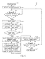
FIG. 5 illustrates a flowchart of a variant of the method ofFIG. 4 . - Referring now to the drawings and specifically to
FIG. 1 , an agricultural implement, namely, a baler, is shown as a round baler 5 that is towed behind atractor 7 by way of a hitch 9 extending from achassis 11 of the baler 5. The baler 5 may be any of a variety of round balers configured for automatic baling, for example, one of the RB 4 series of round balers, such as an RB444, RB454, RB464, RB554, or RB564 round baler available from Case IH. Toward a front end the baler 5, apickup 13 extends downwardly from thechassis 11. Thepickup 13 hastines 15 that rotate to collect cutcrop material 17 from awindrow 19 for delivery into abale chamber 21. Thebale chamber 21 is provided in anenclosure 23 defined by afront portion 25 having interconnectedwalls 27. Toward a back end of the baler 5, aback portion 29 of theenclosure 23 defines atailgate 31 having interconnectedwalls 33 and that is arranged with respect to thefront portion 25 of theenclosure 23 to pivot and raise open for ejecting a bale from the baler 5. Inside theenclosure 23, a series of belts (not shown) is supported for traveling along a path that partially defines thebale chamber 21, such as at a rear-facing portion of thebale chamber 21, to accommodate rolling of the bale while controlling the cylindrical bale shape as the bale grows within thebale chamber 21.Multiple rollers 35 are arranged at a forward facing portion of thebale chamber 21. Therollers 35 may include, for example, a powered floor roll to support the weight of the bale as it is being formed, a starter roll for beginning bale formation in working with the belts to grow the bale shape, a fixed roll to assist with core formation of the bale, and pivot and ribbed stripper rolls to assist with bale formation and maintaining bale shape. During bale formation, a size(s) of abale 37 may be detected by one or morebale size sensors 39 arranged with respect to thebale chamber 21 for sensing the size of the bale 37during its formation. - Still referring to
FIG. 1 , awrapper assembly 41 is arranged within theenclosure 23 for providingwrapping material 43 onto fully formedbales 37. The wrappingmaterial 43 is stored on aroll 45 toward the front of theenclosure 23. The wrappingmaterial 43 may be a net or mesh type of material. Acam 47 is used for inserting and applying the wrappingmaterial 43 onto thebale 41 when thebale 37 has achieved full size. Referring now toFIGS. 2 and 3 , thecam 47 has aslot 49 in a first arm 51 that guides movement to thecam 47 to pivot about apivot point 53 defined at abase 55 of thecam 47. Asecond arm 57 extends from the base 55 in a generally opposite direction with respect to the first arm 51. Aduckbill clamp 59 is arranged at an end of thesecond arm 57. Theduckbill clamp 59 is configured to allow one-way travel of the wrappingmaterial 43 through thewrapper assembly 41. Theduckbill clamp 59 holds a portion of the wrappingmaterial 43 exposed for insertion into thebale chamber 21 and application of the wrappingmaterial 43 onto thebale 37 during a bale wrapping procedure that occurs when thebale 37 is fully formed and thus full size. Anactuator 61 is arranged within theenclosure 23 for moving thecam 47 from a home position (FIG. 2 ) to a start wrap position (FIG. 3 ), as explained in greater detail elsewhere herein. In one embodiment, theactuator 61 is an electronic actuator such as an electronic linear actuator that has amovable rod 63 that is connected to alobe 65 at thebase 55 of thecam 47 for pivoting thecam 47 about thepivot 53. - Referring now to
FIG. 2 , thewrapper assembly 41 and itscam 47 are shown in the home position. When in the home position, thewrapper assembly 41 is arranged with respect to the bale chamber 21 (FIG. 1 ) to allow the forming of thebale 37 within thebale chamber 21, with theduckbill clamp 59 in a position that is relatively further from thebale 37. Referring now toFIG. 3 , thewrapper assembly 41 and itscam 47 are shown in the start wrap position. When in the start wrap position, thewrapper assembly 41 is arranged with respect to the bale chamber 21 (FIG. 1 ) to allow the wrappingmaterial 43 carried by thewrapper assembly 41 to be applied to thebale 37 during a bale wrapping procedure, with theduckbill clamp 59 in a position that is relatively closer to thebale 37. Referring again toFIGS. 2 and 3 , to move thewrapper assembly 41 and itscam 47 from the home position (FIG. 2 ) to a start wrap position (FIG. 3 ), theactuator 61 is energized. Energizingactuator 61 extends therod 63 from a fully retracted position when thewrapper assembly 41 is in the home position (FIG. 2 ), outwardly. Extending therod 63 pushes an end of therun 63 against thelobe 65 of thecam 47. This causes thecam 47 to pivot about thepivot 53, moving theduckbill clamp 59 and the wrappingmaterial 43 closer to thebale 37. When therod 63 moves outwardly to a fully extended position (FIG. 3 ), thewrapper assembly 41 and itscam 47 correspondingly move to a location defining the start wrap position. - Referring now to
FIGS. 1-3 , aconductor 66 operably connects theactuator 61 to abaler controller 67 for controlling operation of theactuator 61. Referring now toFIG. 1 , thebaler controller 67 is configured for controlling operations of the baler 5, including controlling bale forming and wrapping related operations of the baler 5. Thebaler controller 67 includes a controller 69 and power supply 71, as is known in automatic round balers, for controlling the functions of the baler 5 by controlling the various electronic actuators, hydraulic systems, and/or other systems of the baler 5. The controller 69 can include an industrial computer or, e.g., a programmable logic controller (PLC), along with corresponding software and suitable memory for storing such software and hardware including interconnecting conductors for power and signal transmission for controlling electronic, electro-mechanical, and hydraulic components of the baler 5. Abaler interface system 73 is operably connected to thebaler controller 67 and includes a monitor and various input devices to allow an operator to see the statuses and control various operations of the baler 5, for example, from within a cab of thetractor 7. Thebaler interface system 73 may be a Deluxe Control Monitor™ interface available for use with RB 4 series of round balers from Case IH. - Still referring to
FIG. 1 , thebaler controller 67 is part of acontrol system 75 that includes atractor controller 77 operably communicating with thebaler controller 67, for example, by way of an ISOBUS connection, for coordinating controls of the baler andtractor 5, 7. Thetractor controller 77 is configured for controlling operations of thetractor 7 such as controlling travel speed related operations of thetractor 7, including controlling speed, braking, shifting, and other operations of thetractor 7. Thetractor controller 77 includes a controller79and power supply 81, as is known, for controlling the functions of thetractor 7 by controlling the various transmission, engine, hydraulic, and/or other systems of thetractor 7. Like the controller 69 of thebaler controller 67, the controller 79 of thetractor controller 77 can include an industrial computer or, e.g., a programmable logic controller (PLC), along with corresponding software and suitable memory for storing such software and hardware including interconnecting conductors for power and signal transmission for controlling electronic, electro-mechanical, and hydraulic components of thetractor 7. Atractor interface system 83 is operably connected to thetractor controller 77 and includes a monitor and various input devices to allow an operator to see the statuses and control various operations of thetractor 7 from within the cab of thetractor 7. Thetractor interface system 83 may be a MultiControl Armrest™ console available for use with Maxxum™ series tractors from Case IH. - Still referring to
FIG. 1 , thecontrol system 75 is configured so that the baler andtractor controllers tractor 7 to slow and stop thetractor 7 as a function of a status of a baler 5. Such status of the baler 5 may include such characteristics as a movement initiation event of thewrapper assembly 41, a position of thewrapper assembly 41, and/or how long it may take for thewrapper assembly 41 to move from the home position to the wrap start position. Referring again toFIGS. 2 and 3 , a sensor(s) 85 is arranged for detecting movement of thewrapper assembly 41 to allow thecontrol system 75 to coordinate and synchronize slowing and stopping of thetractor 7 with thewrapper assembly 41, reaching the wrap start position. In one embodiment, thesensor 85 is arranged with respect to theactuator 61 and/ or conductor -66 for monitoring electrical current draw of and thus energizing of theactuator 61. Thesensor 85 may be a current sensor to directly detect and monitor current draw of theactuator 61 or may be another sensor configured to detect, for example, voltage and resistance across theactuator 61 for indirectly monitoringcurrent draw actuator 61. Other ways of detecting movement of thewrapper assembly 41 may include using yet another type of sensor(s) 85, such as potentiometers, hall effect and on/off sensors such as limit switches, magnetic, ultrasonic and infrared sensors operatively connected to thecontrol system 75 for detecting such movement(s). In one embodiment, energizing or initiation of movement of theactuator 61 is detected by thecontrol system 75. Based on this detection of movement initiation of theactuator 61 and the time period required to move the wrapper assembly from the home position to the wrap start position, thecontrol system 75 controls the speed of thetractor 7 to coordinate and synchronize bringing thetractor 7 to a complete stop at the same time that thewrapper assembly 41 reaches the wrap start position. - Referring now to
FIG. 4 and with further reference toFIG. 1 , an exemplary method for coordinating automatically stopping a tractor with wrapping a bale in a baler is shown as represented bynumeral 87. As represented atblocks tractor 7 is driven to tow a baler 5 while aligning the baler 5 with respect to awindrow 19 ofcut crop material 17 for automatically forming abale 37 with the baler 5. When thebaler controller 67 detects that thebale 37 has achieved full size, thebaler controller 67 commands movement of thewrapper assembly 41 from a home position (FIG. 2 ) to a start wrap position (FIG. 3 ). As represented atblock 93, movement of the wrapper assembly from the home position toward the start wrap position is detected. This may be done by way ofsensor 85 that detects current draw of theactuator 61 and sends a corresponding signal(s) that is monitored and evaluated by thebaler controller 67, which may be indicative of initiation of movement of thewrapper assembly 41. - Still referring to
FIG. 4 with further reference toFIG. 1 , as represented atblock 95, thecontrol system 75, such as thebaler controller 67, starts a timer at a time (Tactuator start) corresponding to a time of detected movement of thewrapper assembly 41 from the home position toward the start wrap position. As represented atblock 97, thecontrol system 75, such as thetractor controller 77, determines a first time period value (Tuntil stop) that corresponds to an amount of time required for thetractor 7 and baler 5 to come to a stop. The Tuntil stop value can be determined as a function of at least one of a tractor speed and an operator setting such as a maximum deceleration rate defined by the operator, for example, through thetractor interface system 83. The Tuntil stop value can be determined by thebaler controller 67 or thetractor controller 77 and communicated back to thebaler controller 67. The Tuntil stop value can be determined based on a stored lookup table configured to be accessible by thebaler controller 67 ortractor controller 77, or based at least in part on a calculated estimate by thecontrol system 75 of time remaining before reaching a complete stop. As represented atblock 99, a second time period value (Tuntil wrap) is determined that corresponds to an amount of time that will elapse before a beginning of the bale wrapping procedure, at which time the wrappingmaterial 43 begins engaging and wrapping onto thebale 37. The Tuntil wrap value is determined based at least in part on a value of Tactuator start value and a known or estimated time required for moving thewrapper assembly 41 from the home position to the start wrap position. The Tuntil wrap value can be determined based on a stored lookup table configured to be accessible by thebaler controller 67, or based at least in part on a calculation of the time duration for moving thewrapper assembly 41 from the home position to the start wrap position, which may be based at least in part on a wrapper type or other characteristic of the wrappingmaterial 43. - Still referring to
FIG. 4 with further reference toFIG. 1 , as represented atblock 101, thecontrol system 75 evaluates the values of Tuntil stop and Tuntil wrap with respect to each other. This may be done by way of thebaler controller 67. As represented atblock 103, thecontrol system 75 stops thetractor 7 based at least in part on the evaluation of the of Tuntil stop and Tuntil wrap values. As represented atblocks 105 and 107, a tractor halt command signal is sent to thetractor 7 to decelerate thetractor 7 to be stopped. This may be done by thebaler controller 67 sending the tractor halt command signal to thetractor controller 77 that executes the deceleration and stopping of thetractor 7. As represented atblock 109, a bale wrapping procedure begins at a time Twrapping start that occurs substantially simultaneously, for example, within less than about five seconds or less than about one second of, a time Tstopped. The time Tstopped is defined when the tractor is completely stopped, for example, initially achieves the complete stop. - Referring now to
FIG. 5 and with further reference toFIGS. 1 and4 , a flowchart of one embodiment of a method for coordinating automatically stopping a tractor with wrapping a bale in a baler by way ofcontrol system 75 is shown as represented bynumeral 111. Atstep 113, baling starts, for example, as described with respect to block 89 ofFIG. 4 . Atstep 115, the operator activates an automatic baling procedure of the baler 5, by way of the baler interface system 73 (FIG. 1 ). Atstep 117, a determination is made whether thewrapper assembly 41, has begun moving from the home position to the wrap start position, for example, as described with respect to block 93 ofFIG. 4 . Atstep 119, detecting the initiation of the movement of thewrapper assembly 41 from the home position to the wrap start position causes a start timer to begin, for example, as described with respect to block 95 ofFIG. 4 . Atsteps blocks FIG. 4 . Atstep 125, the values of Tuntil stop and Tuntil wrap are compared with each other. If the value of Tuntil stop is less than Tuntil wrap, then new values of Tuntil stop and Tuntil wrap are determined at that time by repeatingsteps baler controller 67 sends a tractor halt command signal to thetractor controller 77, for example, as described with respect toblocks 103 and 105 ofFIG. 4 . In one embodiment, thetractor 7 may be stopped when Tuntil stop is equal or nearly equal to but slightly less than Tuntil wrap, such that the difference between Tuntil stop and Tuntil wrap is small enough to allow a bale wrapping procedure to begin substantially simultaneously with the stopping of thetractor 7, for example, within less than about five seconds or less than about one second of each other. Atstep 129, thetractor 7 stops and the bale is wrapped, for example, as described with respect toblocks FIG 4 , and the bale is ejected from the baler 5. Atstep 131, thebaler controller 67 sends a resume travel command signal to thetractor controller 77. This is indicated to the operator through the baler ortractor interface systems 73, 83 (FIG. 1 ) and the operator confirms through the baler ortractor interface system tractor 7 should resume travel. Atstep 135, automatic baling can resume, for example, as permitted by the operator to thebaler interface system 73, at which point thecontrol system 75 returns to step 117 to determine whether thewrapper assembly 41, has begun moving from the home position to the wrap start position. If automatic baling does not resume atstep 135, and the automatic baling is terminated and the baling session ends atstep 137. - Many changes and modifications could be made to the invention without departing from the spirit thereof. The scope of these changes will become apparent from the appended claims.
Claims (16)
- A method for coordinating stopping a tractor (7)with wrapping a bale (37) in a baler (5) while operating the tractor (7) to move the baler (5) with respect to a windrow (19) of cut crop material (17) for picking up the cut crop material (17) with the baler (5), the method comprising:moving a wrapper assembly (41) from a home position at which the wrapper assembly (41) is arranged with respect to a bale chamber (21) of the baler (5) to allow the forming of the bale (37) within the bale chamber (21) to a start wrap position at which the wrapper assembly (41) is arranged with respect to the bale chamber (21) to allow a wrapping material (43) carried by the wrapper assembly (41) to be applied to the bale (37) during a bale wrapping procedure;detecting movement of the wrapper assembly (41) from the home position toward the start wrap position;starting a timer at a time (Tactuator start) corresponding to a time of detected movement of the wrapper assembly (41) from the home position toward the start wrap position;determining a first time period value (Tuntil stop) corresponding to an amount of time required for the tractor (7) and baler (5) to come to a stop as a function of at least one of a tractor speed and an operator setting;determining a second time period value (Tuntil wrap) corresponding to an amount of time that will elapse before a beginning of the bale wrapping procedure based at least in part on a value of Tactuator start;evaluating T until stop with respect to Tuntil wrap;stopping the tractor (7) based at least in part on the evaluation of Tuntil stop with respect to Tuntil wrap to define a time (Tstopped) at which the tractor (7) is completely stopped; andbeginning the bale wrapping procedure at a time (Twrapping start) occurring substantially simultaneously with time Tstopped.
- The method of claim 1, wherein the tractor (7) includes a tractor controller (77) configured for controlling travel speed related operations of the tractor (7), and the baler (5) includes a baler controller (67) configured for controlling bale forming and wrapping related operations.
- The method of claim 2, wherein the baler controller (67) sends a tractor halt command signal to the tractor controller (77) for stopping the tractor (7).
- The method of claim 3, wherein the baler controller (67) sends the tractor halt command signal when the T until stop time period value is greater than the Tuntil wrap time period value.
- The method of claim 3, wherein the tractor halt command signal is sent when the T until stop time period value is equal to or less than the Tuntil wrap time period value.
- The method of claim 3, wherein the baler controller (67) starts the timer at time Tactuator start.
- The method of any of the claims 2 to 6, wherein at least one of the baler controller (67) and the tractor controller (77) determines the Tuntil stop time period value.
- The method of claim 7, wherein the tractor controller (77) communicates the determined Tuntil stop time period value to the baler controller (67).
- The method of claim 7 or 8, wherein the tractor controller (77) determines the determined Tuntil stop time period value based at least in part on a stored lookup table configured to be accessible by the tractor controller (77).
- The method of claim 7 or 8, wherein the tractor controller (77) determines the Tuntil stop time period value based at least in part on a calculated estimate of time remaining before reaching a complete stop.
- The method of any of the preceding claims, wherein at least one of a potentiometer, hall effect sensor, limit switch, magnetic switch, infrared sensor, and ultrasonic sensor is used for detecting movement of the wrapper assembly (41).
- The method of any of the preceding claims, wherein the wrapper assembly (41) includes an electronic actuator (61) and wherein the detecting movement of the wrapper assembly (41) from the home position toward the start wrap position includes monitoring electrical current draw of the actuator (41).
- The method of claim 12, when depending directly or indirectly on claim 2, wherein monitoring the electrical current draw of the actuator (61) includes detecting a change in an electrical current draw of the actuator (61) with the baler controller (67) indicating energizing the actuator (61) for moving the wrapper assembly (41).
- A tractor and baler combination comprising a tractor (7) having a tractor controller (77) configured for controlling travel speed related operations of the tractor (7), and a baler comprising:a chassis (11) configured for towing behind a tractor (7);a pickup (13) supported by the chassis (11) and arranged for alignment with a windrow (19) of crop material (17) for delivering the crop material into the baler (5);a bale chamber (21) arranged with respect to the chassis (11) and the pickup (13) to receive the crop material (17) delivered by the pickup (13) for forming a bale (37) within the bale chamber (21);a wrapper assembly (41) carrying a wrapping material (43) and arranged with respect to the bale chamber (21) to allow the wrapping material (43) to be applied to the bale (37) during a bale wrapping procedure, the wrapper assembly (41) including;a cam (47) configured for moving from a first position corresponding to a home position of the wrapper assembly (41) at which the wrapper assembly (41) is arranged with respect to the bale chamber (21) to allow the forming of the bale (37) within the bale chamber (21) to a second position corresponding to a start wrap position at which the wrapper assembly (41) is arranged with respect to the bale chamber (21) to allow the wrapping material (41) to be applied to the bale (37) during a bale wrapping procedure,an actuator (61) configured for moving the cam (47)between the first and second positions to move the wrapper assembly (41) from the home position to the start wrap position; anda baler controller (67) configured for controlling bale forming and wrapping-related operations of the baler (5) and configured to communicate with the tractor controller (77) of the tractor (7), and wherein the baler controller (67) is configured for detecting movement of the actuator (61) while the actuator (61) begins moving the wrapper assembly (41) from the first position toward the second position by detecting movement of the actuator (41) and to send a tractor halt command signal to the tractor controller (77) based at least in part on detecting movement of the actuator (61).
- The tractor and baler combination of claim 14, wherein the baler controller (67) is configured to start a timer at a time (Tactuator start) corresponding to a time of detected movement of the actuator (61) and determine a time period value (Tuntil wrap) corresponding to an amount of time that will elapse before a beginning of the bale wrapping procedure based at least in part on a value of Tactuator start, and tractor halt command signal is sent based at least in part on the Tuntil wrap time period value.
- The tractor and baler combination of claim 15, wherein at least one of the baler controller (67) and the tractor controller (77) is configured to determine a time period value (Tuntil stop) corresponding to an amount of time required for the tractor (7) and baler (5) to come to a stop, and wherein the baler controller (67) is configured to evaluate T until stop with respect to Tuntil wrap and send the tractor command signal when Tuntil stop is greater than Tuntil wrap such that a wrapping procedure begins at a time (Twrapping start) that occurs substantially simultaneously with a time (Tstopped) defined by the tractor (7) and baler (5) initially achieving a complete stop.
Applications Claiming Priority (1)
| Application Number | Priority Date | Filing Date | Title |
|---|---|---|---|
| US14/097,780 US9008920B1 (en) | 2013-12-05 | 2013-12-05 | Baler automatic stopping sequence |
Publications (2)
| Publication Number | Publication Date |
|---|---|
| EP2883440A1 true EP2883440A1 (en) | 2015-06-17 |
| EP2883440B1 EP2883440B1 (en) | 2018-07-25 |
Family
ID=52016468
Family Applications (1)
| Application Number | Title | Priority Date | Filing Date |
|---|---|---|---|
| EP14196612.7A Active EP2883440B1 (en) | 2013-12-05 | 2014-12-05 | Baler automatic stopping sequence |
Country Status (2)
| Country | Link |
|---|---|
| US (1) | US9008920B1 (en) |
| EP (1) | EP2883440B1 (en) |
Families Citing this family (11)
| Publication number | Priority date | Publication date | Assignee | Title |
|---|---|---|---|---|
| US9526212B2 (en) * | 2014-11-26 | 2016-12-27 | Cnh Industrial America Llc | Baler automatic stopping sequence |
| BE1024469B1 (en) * | 2017-05-09 | 2018-02-28 | Cnh Ind Belgium Nv | AGRICULTURAL SYSTEM |
| JP6854258B2 (en) * | 2018-03-30 | 2021-04-07 | ヤンマーパワーテクノロジー株式会社 | Work vehicle |
| JP7157713B2 (en) * | 2019-07-30 | 2022-10-20 | 株式会社クボタ | Travel and work vehicles |
| US11533853B2 (en) * | 2019-09-12 | 2022-12-27 | Cnh Industrial America Llc | Agricultural vehicle with automatic motor-driven component calibration |
| US20210212262A1 (en) * | 2020-01-09 | 2021-07-15 | Cnh Industrial America Llc | Agricultural baler with wrap completion detection |
| EP4032381B1 (en) * | 2021-01-25 | 2025-01-08 | Kubota Corporation | A system and method for controlling operation of a work vehicle |
| US11622495B2 (en) * | 2021-06-01 | 2023-04-11 | Gint Co., Ltd. | Method of automatically combining farm vehicle and work machine and farm vehicle |
| US12477996B2 (en) | 2022-06-15 | 2025-11-25 | Cnh Industrial America Llc | Agricultural baler with mechanism to limit bale roll after ejection |
| DE102024117250A1 (en) * | 2024-06-19 | 2025-12-24 | Usines Claas France S.A.S | Assistance system and method for controlling at least one agricultural machinery arrangement |
| EP4691220A1 (en) * | 2024-08-09 | 2026-02-11 | Deere & Company | Traction vehicle-baler combination, baler and method for operating a combination or baler |
Citations (3)
| Publication number | Priority date | Publication date | Assignee | Title |
|---|---|---|---|---|
| US5551218A (en) * | 1994-09-19 | 1996-09-03 | Gehl Company | Round baler monitoring and control system |
| EP1813146A2 (en) * | 2006-01-31 | 2007-08-01 | Deere & Company | Tractor and baler combination with automatic baling and steering control |
| US20110238269A1 (en) * | 2010-03-29 | 2011-09-29 | Martin Michael J | Tractor-Implement Control System And Method |
Family Cites Families (13)
| Publication number | Priority date | Publication date | Assignee | Title |
|---|---|---|---|---|
| US5189866A (en) * | 1991-04-08 | 1993-03-02 | Krutza Lloyd J | Element protection cover applicator for round hay bales |
| DE19718831A1 (en) | 1997-05-05 | 1998-11-12 | Claas Usines France | Device and method for regulating the bale length in a large baler |
| EP1121245B1 (en) | 1998-06-18 | 2008-12-24 | Kline & Walker L.L.C. | Automated devices to control equipment and machines with remote control and accountability worldwide |
| US20010047640A1 (en) | 1999-12-16 | 2001-12-06 | Hay Wrap, Inc. | Method and apparatus for forming and wrapping round bales |
| US6622455B2 (en) | 2000-09-12 | 2003-09-23 | Agco Corporation | Round baler with semi-automatically sequenced operating cycles and selectively variable point of operator intervention |
| US7937923B2 (en) | 2007-10-25 | 2011-05-10 | Deere & Company | Tractor and round baler combination with automatic baling and automatic rear door opening |
| EP2149293B1 (en) * | 2008-07-31 | 2011-06-29 | Deere & Company | Baler and wrapper combination |
| US7918072B2 (en) * | 2008-10-10 | 2011-04-05 | Cnh America Llc | Mechanical net wrapper |
| US20110023732A1 (en) * | 2009-07-31 | 2011-02-03 | Agco Corporation | Round Baler With Variable Speed Baling Mechanism |
| US8311709B2 (en) * | 2009-09-08 | 2012-11-13 | Cnh America Llc | Implement initiated control of tractor power take-off (PTO) |
| US8527156B2 (en) | 2009-11-06 | 2013-09-03 | Deere & Company | Tractor-implement control system method |
| DE102011007914A1 (en) | 2011-04-21 | 2012-10-25 | Deere & Company | Data communication interface for an agricultural utility vehicle |
| US8577563B2 (en) | 2011-11-09 | 2013-11-05 | Cnh America Llc | Initiating tractor stop and bale wrap function |
-
2013
- 2013-12-05 US US14/097,780 patent/US9008920B1/en active Active
-
2014
- 2014-12-05 EP EP14196612.7A patent/EP2883440B1/en active Active
Patent Citations (3)
| Publication number | Priority date | Publication date | Assignee | Title |
|---|---|---|---|---|
| US5551218A (en) * | 1994-09-19 | 1996-09-03 | Gehl Company | Round baler monitoring and control system |
| EP1813146A2 (en) * | 2006-01-31 | 2007-08-01 | Deere & Company | Tractor and baler combination with automatic baling and steering control |
| US20110238269A1 (en) * | 2010-03-29 | 2011-09-29 | Martin Michael J | Tractor-Implement Control System And Method |
Also Published As
| Publication number | Publication date |
|---|---|
| EP2883440B1 (en) | 2018-07-25 |
| US9008920B1 (en) | 2015-04-14 |
Similar Documents
| Publication | Publication Date | Title |
|---|---|---|
| US9008920B1 (en) | Baler automatic stopping sequence | |
| US9526212B2 (en) | Baler automatic stopping sequence | |
| EP2319291B1 (en) | Method of controlling a combination of a tractor and a baler coupled to the tractor | |
| EP2901845B1 (en) | Baler with a sensor assembly and computer-implemented method | |
| EP3308631B1 (en) | Agricultural harvesting machine | |
| US9241443B2 (en) | Gate position control of round bale discharge | |
| US10271480B2 (en) | Baler with automated positioning of plunger | |
| EP3308635A1 (en) | Agricultural harvesting machine | |
| EP2947978B1 (en) | Agricultural baler provided with means for preventing incorrect bale length | |
| EP3308634A1 (en) | Agricultural harvesting machine | |
| EP4248731A1 (en) | A baling machine including a knotter and needle combination | |
| US10513181B2 (en) | Speed control system for an agricultural vehicle | |
| US11968929B2 (en) | Agricultural system | |
| EP3308636A1 (en) | Agricultural harvesting machine | |
| EP3672393B1 (en) | A method for operating a round baler and a round baler | |
| US20250048970A1 (en) | Tractor pto control for round baler net damage | |
| EP3782456B1 (en) | Agricultural baler with controlled tailgate lockout | |
| EP4666836A1 (en) | Agricultural implement system with a controller for detecting and mitigating plug conditions | |
| JP7581073B2 (en) | Round Baler |
Legal Events
| Date | Code | Title | Description |
|---|---|---|---|
| PUAI | Public reference made under article 153(3) epc to a published international application that has entered the european phase |
Free format text: ORIGINAL CODE: 0009012 |
|
| 17P | Request for examination filed |
Effective date: 20141205 |
|
| AK | Designated contracting states |
Kind code of ref document: A1 Designated state(s): AL AT BE BG CH CY CZ DE DK EE ES FI FR GB GR HR HU IE IS IT LI LT LU LV MC MK MT NL NO PL PT RO RS SE SI SK SM TR |
|
| AX | Request for extension of the european patent |
Extension state: BA ME |
|
| R17P | Request for examination filed (corrected) |
Effective date: 20151217 |
|
| RBV | Designated contracting states (corrected) |
Designated state(s): AL AT BE BG CH CY CZ DE DK EE ES FI FR GB GR HR HU IE IS IT LI LT LU LV MC MK MT NL NO PL PT RO RS SE SI SK SM TR |
|
| 17Q | First examination report despatched |
Effective date: 20160628 |
|
| STAA | Information on the status of an ep patent application or granted ep patent |
Free format text: STATUS: EXAMINATION IS IN PROGRESS |
|
| GRAP | Despatch of communication of intention to grant a patent |
Free format text: ORIGINAL CODE: EPIDOSNIGR1 |
|
| STAA | Information on the status of an ep patent application or granted ep patent |
Free format text: STATUS: GRANT OF PATENT IS INTENDED |
|
| INTG | Intention to grant announced |
Effective date: 20180305 |
|
| GRAS | Grant fee paid |
Free format text: ORIGINAL CODE: EPIDOSNIGR3 |
|
| GRAA | (expected) grant |
Free format text: ORIGINAL CODE: 0009210 |
|
| STAA | Information on the status of an ep patent application or granted ep patent |
Free format text: STATUS: THE PATENT HAS BEEN GRANTED |
|
| AK | Designated contracting states |
Kind code of ref document: B1 Designated state(s): AL AT BE BG CH CY CZ DE DK EE ES FI FR GB GR HR HU IE IS IT LI LT LU LV MC MK MT NL NO PL PT RO RS SE SI SK SM TR |
|
| REG | Reference to a national code |
Ref country code: GB Ref legal event code: FG4D |
|
| REG | Reference to a national code |
Ref country code: CH Ref legal event code: EP |
|
| REG | Reference to a national code |
Ref country code: AT Ref legal event code: REF Ref document number: 1020781 Country of ref document: AT Kind code of ref document: T Effective date: 20180815 |
|
| REG | Reference to a national code |
Ref country code: IE Ref legal event code: FG4D |
|
| REG | Reference to a national code |
Ref country code: DE Ref legal event code: R096 Ref document number: 602014029038 Country of ref document: DE |
|
| REG | Reference to a national code |
Ref country code: FR Ref legal event code: PLFP Year of fee payment: 5 |
|
| REG | Reference to a national code |
Ref country code: NL Ref legal event code: FP |
|
| REG | Reference to a national code |
Ref country code: LT Ref legal event code: MG4D |
|
| REG | Reference to a national code |
Ref country code: AT Ref legal event code: MK05 Ref document number: 1020781 Country of ref document: AT Kind code of ref document: T Effective date: 20180725 |
|
| PG25 | Lapsed in a contracting state [announced via postgrant information from national office to epo] |
Ref country code: SE Free format text: LAPSE BECAUSE OF FAILURE TO SUBMIT A TRANSLATION OF THE DESCRIPTION OR TO PAY THE FEE WITHIN THE PRESCRIBED TIME-LIMIT Effective date: 20180725 Ref country code: AT Free format text: LAPSE BECAUSE OF FAILURE TO SUBMIT A TRANSLATION OF THE DESCRIPTION OR TO PAY THE FEE WITHIN THE PRESCRIBED TIME-LIMIT Effective date: 20180725 Ref country code: NO Free format text: LAPSE BECAUSE OF FAILURE TO SUBMIT A TRANSLATION OF THE DESCRIPTION OR TO PAY THE FEE WITHIN THE PRESCRIBED TIME-LIMIT Effective date: 20181025 Ref country code: IS Free format text: LAPSE BECAUSE OF FAILURE TO SUBMIT A TRANSLATION OF THE DESCRIPTION OR TO PAY THE FEE WITHIN THE PRESCRIBED TIME-LIMIT Effective date: 20181125 Ref country code: FI Free format text: LAPSE BECAUSE OF FAILURE TO SUBMIT A TRANSLATION OF THE DESCRIPTION OR TO PAY THE FEE WITHIN THE PRESCRIBED TIME-LIMIT Effective date: 20180725 Ref country code: GR Free format text: LAPSE BECAUSE OF FAILURE TO SUBMIT A TRANSLATION OF THE DESCRIPTION OR TO PAY THE FEE WITHIN THE PRESCRIBED TIME-LIMIT Effective date: 20181026 Ref country code: RS Free format text: LAPSE BECAUSE OF FAILURE TO SUBMIT A TRANSLATION OF THE DESCRIPTION OR TO PAY THE FEE WITHIN THE PRESCRIBED TIME-LIMIT Effective date: 20180725 Ref country code: PL Free format text: LAPSE BECAUSE OF FAILURE TO SUBMIT A TRANSLATION OF THE DESCRIPTION OR TO PAY THE FEE WITHIN THE PRESCRIBED TIME-LIMIT Effective date: 20180725 Ref country code: BG Free format text: LAPSE BECAUSE OF FAILURE TO SUBMIT A TRANSLATION OF THE DESCRIPTION OR TO PAY THE FEE WITHIN THE PRESCRIBED TIME-LIMIT Effective date: 20181025 Ref country code: LT Free format text: LAPSE BECAUSE OF FAILURE TO SUBMIT A TRANSLATION OF THE DESCRIPTION OR TO PAY THE FEE WITHIN THE PRESCRIBED TIME-LIMIT Effective date: 20180725 |
|
| PG25 | Lapsed in a contracting state [announced via postgrant information from national office to epo] |
Ref country code: LV Free format text: LAPSE BECAUSE OF FAILURE TO SUBMIT A TRANSLATION OF THE DESCRIPTION OR TO PAY THE FEE WITHIN THE PRESCRIBED TIME-LIMIT Effective date: 20180725 Ref country code: AL Free format text: LAPSE BECAUSE OF FAILURE TO SUBMIT A TRANSLATION OF THE DESCRIPTION OR TO PAY THE FEE WITHIN THE PRESCRIBED TIME-LIMIT Effective date: 20180725 Ref country code: HR Free format text: LAPSE BECAUSE OF FAILURE TO SUBMIT A TRANSLATION OF THE DESCRIPTION OR TO PAY THE FEE WITHIN THE PRESCRIBED TIME-LIMIT Effective date: 20180725 |
|
| REG | Reference to a national code |
Ref country code: DE Ref legal event code: R097 Ref document number: 602014029038 Country of ref document: DE |
|
| PG25 | Lapsed in a contracting state [announced via postgrant information from national office to epo] |
Ref country code: EE Free format text: LAPSE BECAUSE OF FAILURE TO SUBMIT A TRANSLATION OF THE DESCRIPTION OR TO PAY THE FEE WITHIN THE PRESCRIBED TIME-LIMIT Effective date: 20180725 Ref country code: ES Free format text: LAPSE BECAUSE OF FAILURE TO SUBMIT A TRANSLATION OF THE DESCRIPTION OR TO PAY THE FEE WITHIN THE PRESCRIBED TIME-LIMIT Effective date: 20180725 Ref country code: CZ Free format text: LAPSE BECAUSE OF FAILURE TO SUBMIT A TRANSLATION OF THE DESCRIPTION OR TO PAY THE FEE WITHIN THE PRESCRIBED TIME-LIMIT Effective date: 20180725 Ref country code: RO Free format text: LAPSE BECAUSE OF FAILURE TO SUBMIT A TRANSLATION OF THE DESCRIPTION OR TO PAY THE FEE WITHIN THE PRESCRIBED TIME-LIMIT Effective date: 20180725 |
|
| PG25 | Lapsed in a contracting state [announced via postgrant information from national office to epo] |
Ref country code: SK Free format text: LAPSE BECAUSE OF FAILURE TO SUBMIT A TRANSLATION OF THE DESCRIPTION OR TO PAY THE FEE WITHIN THE PRESCRIBED TIME-LIMIT Effective date: 20180725 Ref country code: SM Free format text: LAPSE BECAUSE OF FAILURE TO SUBMIT A TRANSLATION OF THE DESCRIPTION OR TO PAY THE FEE WITHIN THE PRESCRIBED TIME-LIMIT Effective date: 20180725 Ref country code: DK Free format text: LAPSE BECAUSE OF FAILURE TO SUBMIT A TRANSLATION OF THE DESCRIPTION OR TO PAY THE FEE WITHIN THE PRESCRIBED TIME-LIMIT Effective date: 20180725 |
|
| PLBE | No opposition filed within time limit |
Free format text: ORIGINAL CODE: 0009261 |
|
| STAA | Information on the status of an ep patent application or granted ep patent |
Free format text: STATUS: NO OPPOSITION FILED WITHIN TIME LIMIT |
|
| 26N | No opposition filed |
Effective date: 20190426 |
|
| REG | Reference to a national code |
Ref country code: CH Ref legal event code: PL |
|
| PG25 | Lapsed in a contracting state [announced via postgrant information from national office to epo] |
Ref country code: MC Free format text: LAPSE BECAUSE OF FAILURE TO SUBMIT A TRANSLATION OF THE DESCRIPTION OR TO PAY THE FEE WITHIN THE PRESCRIBED TIME-LIMIT Effective date: 20180725 Ref country code: SI Free format text: LAPSE BECAUSE OF FAILURE TO SUBMIT A TRANSLATION OF THE DESCRIPTION OR TO PAY THE FEE WITHIN THE PRESCRIBED TIME-LIMIT Effective date: 20180725 Ref country code: LU Free format text: LAPSE BECAUSE OF NON-PAYMENT OF DUE FEES Effective date: 20181205 |
|
| REG | Reference to a national code |
Ref country code: IE Ref legal event code: MM4A |
|
| REG | Reference to a national code |
Ref country code: BE Ref legal event code: MM Effective date: 20181231 |
|
| PG25 | Lapsed in a contracting state [announced via postgrant information from national office to epo] |
Ref country code: IE Free format text: LAPSE BECAUSE OF NON-PAYMENT OF DUE FEES Effective date: 20181205 |
|
| PG25 | Lapsed in a contracting state [announced via postgrant information from national office to epo] |
Ref country code: BE Free format text: LAPSE BECAUSE OF NON-PAYMENT OF DUE FEES Effective date: 20181231 |
|
| PG25 | Lapsed in a contracting state [announced via postgrant information from national office to epo] |
Ref country code: LI Free format text: LAPSE BECAUSE OF NON-PAYMENT OF DUE FEES Effective date: 20181231 Ref country code: CH Free format text: LAPSE BECAUSE OF NON-PAYMENT OF DUE FEES Effective date: 20181231 |
|
| PG25 | Lapsed in a contracting state [announced via postgrant information from national office to epo] |
Ref country code: MT Free format text: LAPSE BECAUSE OF NON-PAYMENT OF DUE FEES Effective date: 20181205 |
|
| PG25 | Lapsed in a contracting state [announced via postgrant information from national office to epo] |
Ref country code: TR Free format text: LAPSE BECAUSE OF FAILURE TO SUBMIT A TRANSLATION OF THE DESCRIPTION OR TO PAY THE FEE WITHIN THE PRESCRIBED TIME-LIMIT Effective date: 20180725 |
|
| PG25 | Lapsed in a contracting state [announced via postgrant information from national office to epo] |
Ref country code: PT Free format text: LAPSE BECAUSE OF FAILURE TO SUBMIT A TRANSLATION OF THE DESCRIPTION OR TO PAY THE FEE WITHIN THE PRESCRIBED TIME-LIMIT Effective date: 20180725 |
|
| PG25 | Lapsed in a contracting state [announced via postgrant information from national office to epo] |
Ref country code: CY Free format text: LAPSE BECAUSE OF FAILURE TO SUBMIT A TRANSLATION OF THE DESCRIPTION OR TO PAY THE FEE WITHIN THE PRESCRIBED TIME-LIMIT Effective date: 20180725 Ref country code: HU Free format text: LAPSE BECAUSE OF FAILURE TO SUBMIT A TRANSLATION OF THE DESCRIPTION OR TO PAY THE FEE WITHIN THE PRESCRIBED TIME-LIMIT; INVALID AB INITIO Effective date: 20141205 Ref country code: MK Free format text: LAPSE BECAUSE OF NON-PAYMENT OF DUE FEES Effective date: 20180725 |
|
| PGFP | Annual fee paid to national office [announced via postgrant information from national office to epo] |
Ref country code: GB Payment date: 20231218 Year of fee payment: 10 |
|
| PGFP | Annual fee paid to national office [announced via postgrant information from national office to epo] |
Ref country code: NL Payment date: 20231220 Year of fee payment: 10 |
|
| REG | Reference to a national code |
Ref country code: NL Ref legal event code: MM Effective date: 20250101 |
|
| GBPC | Gb: european patent ceased through non-payment of renewal fee |
Effective date: 20241205 |
|
| PG25 | Lapsed in a contracting state [announced via postgrant information from national office to epo] |
Ref country code: NL Free format text: LAPSE BECAUSE OF NON-PAYMENT OF DUE FEES Effective date: 20250101 |
|
| PG25 | Lapsed in a contracting state [announced via postgrant information from national office to epo] |
Ref country code: GB Free format text: LAPSE BECAUSE OF NON-PAYMENT OF DUE FEES Effective date: 20241205 |
|
| PGFP | Annual fee paid to national office [announced via postgrant information from national office to epo] |
Ref country code: IT Payment date: 20251218 Year of fee payment: 12 |
|
| PGFP | Annual fee paid to national office [announced via postgrant information from national office to epo] |
Ref country code: FR Payment date: 20251223 Year of fee payment: 12 |
|
| PGFP | Annual fee paid to national office [announced via postgrant information from national office to epo] |
Ref country code: DE Payment date: 20251229 Year of fee payment: 12 |