EP2883100B1 - Fiber optic splicing assembly - Google Patents
Fiber optic splicing assembly Download PDFInfo
- Publication number
- EP2883100B1 EP2883100B1 EP13765517.1A EP13765517A EP2883100B1 EP 2883100 B1 EP2883100 B1 EP 2883100B1 EP 13765517 A EP13765517 A EP 13765517A EP 2883100 B1 EP2883100 B1 EP 2883100B1
- Authority
- EP
- European Patent Office
- Prior art keywords
- reel
- slide
- fiber optic
- intermediate shaft
- support shaft
- Prior art date
- Legal status (The legal status is an assumption and is not a legal conclusion. Google has not performed a legal analysis and makes no representation as to the accuracy of the status listed.)
- Active
Links
Images






Classifications
-
- G—PHYSICS
- G02—OPTICS
- G02B—OPTICAL ELEMENTS, SYSTEMS OR APPARATUS
- G02B6/00—Light guides; Structural details of arrangements comprising light guides and other optical elements, e.g. couplings
- G02B6/44—Mechanical structures for providing tensile strength and external protection for fibres, e.g. optical transmission cables
- G02B6/4439—Auxiliary devices
- G02B6/444—Systems or boxes with surplus lengths
- G02B6/4441—Boxes
-
- G—PHYSICS
- G02—OPTICS
- G02B—OPTICAL ELEMENTS, SYSTEMS OR APPARATUS
- G02B6/00—Light guides; Structural details of arrangements comprising light guides and other optical elements, e.g. couplings
- G02B6/24—Coupling light guides
- G02B6/36—Mechanical coupling means
- G02B6/38—Mechanical coupling means having fibre to fibre mating means
- G02B6/3801—Permanent connections, i.e. wherein fibres are kept aligned by mechanical means
- G02B6/3803—Adjustment or alignment devices for alignment prior to splicing
-
- G—PHYSICS
- G02—OPTICS
- G02B—OPTICAL ELEMENTS, SYSTEMS OR APPARATUS
- G02B6/00—Light guides; Structural details of arrangements comprising light guides and other optical elements, e.g. couplings
- G02B6/44—Mechanical structures for providing tensile strength and external protection for fibres, e.g. optical transmission cables
- G02B6/4439—Auxiliary devices
- G02B6/4457—Bobbins; Reels
-
- G—PHYSICS
- G02—OPTICS
- G02B—OPTICAL ELEMENTS, SYSTEMS OR APPARATUS
- G02B6/00—Light guides; Structural details of arrangements comprising light guides and other optical elements, e.g. couplings
- G02B6/46—Processes or apparatus adapted for installing or repairing optical fibres or optical cables
- G02B6/47—Installation in buildings
- G02B6/475—Mechanical aspects of installing cables in ducts or the like for buildings
Definitions
- the present invention relates to a fiber optic splicing assembly, more particularly, relates to a fiber optic splicing assembly having a reel and being mountable to a mounting wall.
- a conventional fiber optic splicing enclosure generally comprises a fiber storing device and a plurality of intermediate shafts provided on a tray.
- the fiber storing device is used to store a redundant fiber
- the plurality of intermediate shafts are used to mount fiber optic splicing devices, for example, mechanical splicing devices, fusion splicing devices, etc., for coupling different fibers.
- the fiber storing device of the conventional fiber optic splicing enclosure is not adapted to store an optical cable having a diameter larger than that of the fiber.
- a predetermined length of redundant optical cable must be reserved outside the splicing enclosure according to an arrangement of the splicing enclosure and a support panel for supporting the splicing enclosure.
- the reserved redundant optical cable is too short, it may have a disadvantageous effect on the splicing of fibers.
- the reserved redundant optical cable is too long, it may be hard to maintain and manage the optical cable and its fiber.
- CN 202583564 U discloses an optical fiber splice box which comprises a main box having a cutting portion for cutting a wall body.
- a spool for storing an optical fiber is integrally and monolithically formed with a splicing panel of which a front side is configured to mount a fiber optic splicing device.
- US 2008/011514 A1 describes a system and apparatus for storing an organizing optical fibers and fiber dispensing reel including a housing having multiple mandrels configured to receive one or more fiber dispending reels, as well as a wall module to be disposed at least partially in the hollow space of a wall.
- the present invention has been made to overcome or alleviate at least one aspect of the above mentioned disadvantages.
- a fiber optic splicing assembly in which a reel of a fiber storing device has a retraction state where the reel is retracted into a mounting hole in a mounting wall and a expansion state where the reel is extended out of the mounting hole, facilitating the management and operation on the redundant optical cable and/or fiber.
- a fiber optic splicing assembly mountable to a mounting wall with a mounting hole, comprising: a splicing panel of which a front side is configured to mount a fiber optic splicing device for splicing fibers; a fiber storing device configured to be at least partially received in the mounting hole, wherein the fiber storing device comprises a bracket mounted to the mounting wall and a reel for pre-storing an optical cable and/or fiber, said reel being mounted on the bracket and being removably mounted to a rear side of the splicing panel, wherein the bracket comprises a support shaft, and the reel is movably sleeved onto the support shaft so that the reel is axially movable relative to the support shaft from a retraction state where the reel is located in the mounting hole to a expansion state where the reel is exposed outside the mounting hole; and when the reel is in the expansion state, an operator can unreel the optical cable or fiber stored on the reel from an outside of the mounting wall
- the fiber storing device further comprises an intermediate shaft having a first end connected to the reel in a manner of being axially movable and a second end connected to the support shaft in a manner of being axially movable.
- the intermediate shaft has a substantially tube-like structure and is slidably sleeved onto the support shaft.
- a plurality of slide grooves extending in an axial direction are formed in one of an inner surface of the intermediate shaft and an outer surface of the support shaft; and a plurality of slide protrusions for being slidably fitted in respective slide grooves are formed on the other of the inner surface of the intermediate shaft and the outer surface of the support shaft.
- the slide grooves are formed in the outer surface of the support shaft, and the slide protrusions are formed in the inner surface of the intermediate shaft adjacent to the first end.
- the slide groove is provided with a first block projection and a first limit projection at a position adjacent to a free end of the support shaft; and when the reel is converted from the retraction state to the expansion state in a first slide direction, the first block projection is locked with the slide protrusion to block the intermediate shaft from being disengaged from the free end, and the first limit projection is snapped with the slide protrusion to limit the intermediate shaft from being slid in a second slide direction opposite to the first slide direction.
- the slide grooves comprise at least one first slide groove and at least one second slide groove
- the slide protrusions comprise at least one first slide protrusion and at least one second slide protrusion
- the first slide groove is provided with a first block projection at a position adjacent to a free end of the support shaft
- the second slide groove is provided with a first limit projection at a position adjacent to the free end of the support shaft
- the first end of the intermediate shaft is engaged into a cylindrical body of the reel in a manner of being axially movable.
- the cylindrical body is provided with a ring protrusion inside a first end thereof, and the ring protrusion is rotatably fitted with the outer surface of the intermediate shaft adjacent to the first end of the intermediate shaft.
- a plurality of second block projections are provided on the first end of the intermediate shaft, and the second block projection is configured to lock with a side edge of the ring protrusion far away from the first end of the cylindrical body so as to block the reel from being disengaged from the first end of the intermediate shaft when the reel is converted from the retraction state to the expansion state.
- a plurality of second limit projections are provided on the ring protrusion, and a ring groove is formed in the outer surface of the intermediate shaft, and the second limit projection is configured to snap with the ring groove so as to limit the intermediate shaft from sliding in a second slide direction opposite to a first slide direction when the reel is converted from the retraction state to the expansion state in the first slide direction.
- a ring skirt portion is provided inside a second end of the cylindrical body, and a gap is formed between the ring skirt portion and an inner wall of the cylindrical body; and when the reel is in the retraction state, the ring skirt portion is located between the second end of the intermediate shaft and the free end of the support shaft, so that the reel is rotatable relative to the support shaft and the intermediate shaft.
- the bracket comprising: a base on which the support shaft is supported; and a plurality of support arms extending from an edge of the base, wherein the bracket is mounted to the mounting wall by means of the support arms.
- a free end of the support arm is provided with a flange capable of being engaged to a front side of the mounting wall.
- the flange is provided with a fixation pin capable of being inserted into the mounting wall.
- the bracket further comprises a plurality of groups of positioning devices extending from an edge of the support arms, and the positioning devices and the support arms are arranged alternately.
- each group of positioning devices comprises a plurality of positioning elastic sheets having different length with each other.
- the positioning elastic sheet is provided with a positioning projection.
- the support arm is flexible, and a circumference formed by the support arms has an outer diameter larger than a diameter of the mounting hole; and when the support arms are mounted into the mounting hole, the support arms are elastically deformed and exert an elastic stress on the mounting hole to fix the support arms in the mounting hole.
- the base is provided with a plurality of elastic pieces inwardly protruded.
- the fiber storing device further comprises an intermediate shaft having a first end rotatably and axial-slidably connected to the support shaft and a second end axial-movably connected to the reel.
- a plurality of slide grooves extending in an axial direction are formed in one of an inner surface of the reel and an outer surface of the support shaft; and a plurality of slide protrusions for being slidably fitted in respective slide grooves are formed on the other of the inner surface of the reel and the outer surface of the support shaft.
- a plurality of slide grooves extending in an axial direction are formed in one of an outer surface of the reel and an inner surface of the support shaft; and a plurality of slide protrusions for being slidably fitted in respective slide grooves are formed on the other of the outer surface of the reel and the inner surface of the support shaft.
- the bracket is further formed with an engagement portion fixed to the splicing panel in a snap-fit manner.
- the optical cable and/or fiber having a sufficient length can be pre-stored in the reel before installing the splicing panel, facilitating the operator to quickly unreel the optical cable or fiber from the fiber optic splicing assembly in the maintenance and management operation after the fiber optic splicing assembly has been mounted to the mounting wall.
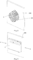
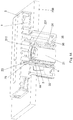
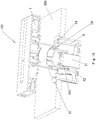
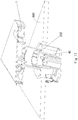
- Fig.1 is an exploded view of a fiber optic splicing assembly 100 according to an exemplary embodiment of the present invention.
- the fiber optic splicing assembly 100 may be applied to splice fibers of different optical cables according to a general invention concept.
- the fiber optic splicing assembly 100 of the present invention may be mounted to a mounting wall 200 with a mounting hole 201 (please refer to Fig.6 ).
- the fiber optic splicing assembly 100 mainly comprises a splicing panel 1 and a fiber storing device 10.
- the splicing panel 1 may be constructed as a conventional splicing panel.
- the splicing panel 1 comprises a fiber optic splicing device 11 for splicing fibers, a mounting assembly for mounting the fiber optic splicing device 11, and a storing device 12 for storing a redundant fiber.
- the fiber optic splicing assembly 100 further comprises a cover 5 covered on the splicing panel 1.
- a rear side of the splicing panel 1 is removably mounted on a front side of the mounting wall 200, and a front side of the splicing panel 1 is configured to mount the fiber optic splicing device 11 for splicing fibers.
- the fiber storing device 10 is configured to be at least partially received in the mounting hole 201, and one end of the fiber storing device 10 is removably mounted to the splicing panel 1.
- the bracket 3 comprises a support shaft 31 having a free end (please refer to Fig.9 ), and the reel 2 is movably sleeved onto the support shaft 31 so that the reel 2 can be axially moved relative to the support shaft 31 from a retraction state where the reel 2 is located in the mounting hole 201 to a expansion state where the reel 2 is exposed outside the mounting hole 201.
- the reel 2 is in the expansion state, an operator can unreel the optical cable or fiber stored on the reel 2 from an outside of the mounting wall 200.
- the reel 2 is rotatably sleeved onto the support shaft 31 and is received in the bracket 3.
- the intermediate shaft 4 is engaged to the support shaft 31 in a manner of being axially movable, and the first end (a left end shown in Fig.1 , or an upper end shown in Fig.13 ) of the intermediate shaft 4 is rotatably engaged to the reel 2.
- the intermediate shaft 4 is slidably engaged to the support shaft 31 in a profile matching manner, that is, the intermediate shaft 4 and the support shaft 31 have structures mated with each other in shape. In this way, it can prevent the intermediate shaft 4 from being rotated relative to the support shaft 31.
- the intermediate shaft 4 has a substantially tube-like structure and is slidably sleeved onto the support shaft 31. Furthermore, a plurality of slide grooves extending in the axial direction are formed in one of an inner surface of the intermediate shaft 4 and an outer surface of the support shaft 31, and a plurality of slide protrusions for being slidably fitted in respective slide grooves are formed on the other of the inner surface of the intermediate shaft 4 and the outer surface of the support shaft 31.
- the slide grooves are formed in the outer surface of the support shaft 31, and the slide protrusions are formed in the inner surface of the intermediate shaft 4 adjacent to the first end (a lower end shown in Fig.13 ).
- the intermediate shaft 4 can be slid in the axial direction with the slide protrusions fitted in the respective slide grooves of the support shaft 31, and cannot be rotated relative to the support shaft 31 because of the blocking function of the slide protrusions.
- the slide protrusions may be formed in the outer surface of the support shaft 31, and the slide grooves may be formed in the inner surface of the intermediate shaft 4 adjacent to the first end.
- the slide grooves formed in the support shaft 31 comprise at least one first slide groove 311 and at least one second slide groove 316
- the slide protrusions formed on the inner surface of the intermediate shaft 4 comprise at least one first slide protrusion 42 and at least one second slide protrusion 43.
- the first slide groove 311 is provided with a first block projection 312 at a position adjacent to the free end (a tip end) of the support shaft 31, and the second slide groove 316 is provided with a first limit projection 313 at a position adjacent to the free end of the support shaft 31.
- the first block projection 312 is locked with the first slide protrusion 42 ( Fig. 15 ) to block the intermediate shaft 4 from being disengaged from the free end of the support shaft 31, and the first limit projection 313 is snapped with the second slide protrusion 43 ( Fig. 16 ) to limit the intermediate shaft 4 from being slid in a second slide direction (a downward direction of Fig.16 ) opposite to the first slide direction.
- the first block projection 312 and the first limit projection 313 each has a matching surface substantially perpendicular to the axial direction, therefore, once the first block projection 312 is matched with the first slide protrusion 42 by sliding the intermediate shaft 4, the intermediate shaft 4 cannot be further moved forward regardless of an force exerted on it unless a matching structure of the first block projection 312 and the first slide protrusion 42 is broken. That is, the first block projection 312 is matched with the first slide protrusion 42 in a lock-fit manner.
- the first limit projection 313 and the second slide protrusion 43 each has a matching surface inclined to the axial direction, therefore, during sliding the intermediate shaft 4 from the retraction state to the expansion state, a relative large force is exerted on it in the first slide direction so that the second slide protrusion 43 can slide across the first limit projection 313 due to a flexible deformation of the second slide protrusion 43 and then position the intermediate shaft 4 in the expansion state. Thereafter, when the force is removed, the first limit projection 313 limits the second slide protrusion 43 from being moved in the second slide direction (a downward direction of Fig.16 ) opposite to the first slide direction.
- first limit projection 313 to the second slide protrusion 43 can be released and that the intermediate shaft 4 can be moved downward as shown in Fig.16 when a relative large force is exerted on the intermediate shaft 4 in the second slide direction. That is, the first limit projection 313 is matched with the second slide protrusion 43 in a snap-fit manner.
- the reel 2 comprises a cylindrical body 21 and flanges 22 formed at both ends of the cylindrical body 21.
- a notch 26 is formed in the flange 22 for the optical cable or fiber passing therethrough.
- the first end (an upper end of Figs.12 and 13 ) of the intermediate shaft 4 is engaged into the cylindrical body 21 of the reel 2 in a manner of being axially movable.
- the cylindrical body 21 is provided with a ring protrusion 24 inside a first end (a lower end of Figs. 10 and 11 ) of the cylindrical body 21, the ring protrusion 24 is rotatably fitted with the outer surface of the intermediate shaft 4 adjacent to the first end of the intermediate shaft 4.
- an engagement portion 25 is formed on and extended from the cylindrical body 21 of the reel 2 for fixing the reel 2 to the splicing panel 1 in a snap-in manner.
- a plurality of second block projections 44 are provided on the first end (an upper end in Figs. 12, 13 ) of the intermediate shaft 4, and the second block projections 44 are configured to lock with a side edge 241 of the ring protrusion 24 far away from the first end (a lower end in Figs. 10, 11 ) of the cylindrical body 21 so as to block the reel 2 from being disengaged from the first end of the intermediate shaft 4 when the reel 2 is in the expansion state.
- the second block projections 44 and the side edge 241 each has a matching surface substantially perpendicular to the axial direction.
- a plurality of second limit projections 242 are provided on the ring protrusion 24, and a ring groove 45 is formed in the outer surface of the intermediate shaft 4.
- the second limit projection 242 is snapped with the ring groove 45 so as to limit the intermediate shaft 4 from being slid in the second slide direction opposite to the first slide direction.
- a ring skirt portion 23 is provided inside a second end (an upper end in Figs. 10, 11 ) of the cylindrical body 21, and there is a gap 232 between the ring skirt portion 23 and an inner wall of the cylindrical body 21.
- the ring skirt portion 23 is located between the second end of the intermediate shaft 4 and the free end of the support shaft 31 (as shown in Fig. 14 ), so that the reel 2 can be rotated relative to the support shaft 31 and the intermediate shaft 4.
- a ring limit projection 231 is formed on the ring skirt portion 23, and a third limit projection 315 (referring to Fig.9 ) is provided on the free end of the support shaft 31.
- the ring limit projection 231 is snapped with the third limit projection 315 so as to limit the reel 2 from being moved far away from the intermediate shaft 4 when the reel 2 is in the retraction state. In this way, the reel 2 can be stably received in the bracket 3.
- the bracket 3 comprises a base 35 and a plurality of support arms 32.
- the support shaft 31 is supported on the base 35.
- a plurality of support arms 32 extend from an edge of the base 35.
- the bracket 3 is mounted to the mounting wall 200 by means of the support arms 32.
- a free end of the support arm 32 is provided with a flange 34 which is capable of being engaged to a front side of the mounting wall 200.
- the flange 34 is provided with a plurality of fixation pin 341 which are capable of being inserted into the mounting wall 200.
- the bracket 3 further comprises a plurality of groups of positioning devices 33 extending from an edge of the base 35, and the positioning devices 33 and the support arms 32 are arranged alternately.
- Each group of positioning devices 33 comprises a plurality of positioning elastic sheets 331 having different length with each other. Also, the positioning elastic sheet 331 is provided with a positioning projection 332.
- the fiber optic splicing assembly 100 of the present invention when the fiber optic splicing assembly 100 of the present invention is mounted on the mounting wall 200, the fiber optic splicing assembly 100 is forced to pass through the mounting hole 201 from the front side of the mounting wall 200 to the rear side of the mounting wall 200, or the support arms 32 are slightly contracted inwardly to pass through the mounting hole 201 from the rear side of the mounting wall 200 to the front side of the mounting wall 200, and the flange 34 is fixed onto the front side of the mounting wall 20 with the fixation pin 341 of the flange 34.
- the positioning elastic sheets 331 of the positioning devices 33 are abut against the rear side of the mounting wall 200.
- the positioning elastic sheets 331 having a larger length are inserted into the mounting hole 201, and the positioning projections 332 of the positioning elastic sheets 331 are abut against the rear side of the mounting 200, so that the bracket 3 can be reliably mounted on the mounting wall 200.
- the support arm 32 is elastic, and a circumference formed by the support arms 32 has an outer diameter larger than a diameter of the mounting hole 201.
- the support arms 32 are mounted into the mounting hole 201, the support arms are elastically deformed and exert an elastic stress on the mounting hole 201 to fix the support arms 32 in the mounting hole 201.
- the base 35 is provided with a plurality of elastic pieces 36 inwardly protruded.
- two installation holes 14 are formed in the splicing panel 1.
- the splicing panel 1 is provided with at least two installation holes 14 for fixing the splicing panel 1 on the mounting wall 200 in cooperation with screws (not shown). After the splicing panel 1 is mounted on the mounting wall 200 by means of the installation holes 14, as shown in Figs.3-5 , by screwing the screws, the elastic pieces 36 are compressed, and the gap between the rear side of the splicing panel 1 and the front side of the mounting wall 200 can be eliminated, so that the splicing panel 1 is reliably mounted on the mounting wall 200.
Landscapes
- Physics & Mathematics (AREA)
- General Physics & Mathematics (AREA)
- Optics & Photonics (AREA)
- Engineering & Computer Science (AREA)
- Civil Engineering (AREA)
- Structural Engineering (AREA)
- Light Guides In General And Applications Therefor (AREA)
- Storage Of Web-Like Or Filamentary Materials (AREA)
Description
- The present invention relates to a fiber optic splicing assembly, more particularly, relates to a fiber optic splicing assembly having a reel and being mountable to a mounting wall.
- In an optical communication network, fibers from an external optical cable are coupled to respective individual user fibers by splicing so as to constitute the optical communication network. As an apparatus for splicing different fibers, a fiber optic enclosure is widely applied in the optical communication network, and adapted to splice fibers in various mounting conditions, for example, in air, in pipe, or in underground condition.
- A conventional fiber optic splicing enclosure generally comprises a fiber storing device and a plurality of intermediate shafts provided on a tray. The fiber storing device is used to store a redundant fiber, and the plurality of intermediate shafts are used to mount fiber optic splicing devices, for example, mechanical splicing devices, fusion splicing devices, etc., for coupling different fibers.
- However, the fiber storing device of the conventional fiber optic splicing enclosure is not adapted to store an optical cable having a diameter larger than that of the fiber. Thereby, a predetermined length of redundant optical cable must be reserved outside the splicing
enclosure according to an arrangement of the splicing enclosure and a support panel for supporting the splicing enclosure. On the one hand, if the reserved redundant optical cable is too short, it may have a disadvantageous effect on the splicing of fibers. On the other hand, if the reserved redundant optical cable is too long, it may be hard to maintain and manage the optical cable and its fiber. - As for other conventional fiber optic splicing enclosures, although a reel for pre-storing the optical cable is provided therein, the reel cannot be embedded and mounted in a mounting wall. Accordingly, the reel is exposed outside the mounting wall and occupies a large volume, and it has a negative influence on the appearance of the enclosure.
-
CN 202583564 U discloses an optical fiber splice box which comprises a main box having a cutting portion for cutting a wall body. In the splice box disclosed in D1, a spool for storing an optical fiber is integrally and monolithically formed with a splicing panel of which a front side is configured to mount a fiber optic splicing device. -
US 2010/074587 refers to a fiber optic enclosure including a housing and a cable spool assembly connected to an exterior of the housing. The spool assembly includes a drum portion and a strain relief post. -
US 2008/011514 A1 describes a system and apparatus for storing an organizing optical fibers and fiber dispensing reel including a housing having multiple mandrels configured to receive one or more fiber dispending reels, as well as a wall module to be disposed at least partially in the hollow space of a wall. - The present invention has been made to overcome or alleviate at least one aspect of the above mentioned disadvantages.
- Accordingly, it is an object of the present invention to provide a fiber optic splicing assembly that can be quickly mounted to a mounting wall, and a reel of which for storing a redundant optical cable and/or fiber can be at least partly embedded in a mounting hole in the mounting wall.
- Accordingly, it is another object of the present invention to provide a fiber optic splicing assembly, in which a reel of a fiber storing device has a retraction state where the reel is retracted into a mounting hole in a mounting wall and a expansion state where the reel is extended out of the mounting hole, facilitating the management and operation on the redundant optical cable and/or fiber.
According to an aspect of the present invention, there is provided a fiber optic splicing assembly mountable to a mounting wall with a mounting hole, comprising: a splicing panel of which a front side is configured to mount a fiber optic splicing device for splicing fibers; a fiber storing device configured to be at least partially received in the mounting hole,
wherein the fiber storing device comprises a bracket mounted to the mounting wall and a reel for pre-storing an optical cable and/or fiber, said reel being mounted on the bracket and being removably mounted to a rear side of the splicing panel, wherein the bracket comprises a support shaft, and the reel is movably sleeved onto the support shaft so that the reel is axially movable relative to the support shaft from a retraction state where the reel is located in the mounting hole to a expansion state where the reel is exposed outside the mounting hole; and when the reel is in the expansion state, an operator can unreel the optical cable or fiber stored on the reel from an outside of the mounting wall. - In the above-mentioned fiber optic splicing assembly, the reel is rotatably sleeved onto the support shaft.
- In the above-mentioned fiber optic splicing assembly, the fiber storing device further comprises an intermediate shaft having a first end connected to the reel in a manner of being axially movable and a second end connected to the support shaft in a manner of being axially movable.
- In the above-mentioned fiber optic splicing assembly, the reel is rotatably engaged to the first end of the intermediate shaft.
- In the above-mentioned fiber optic splicing assembly, the intermediate shaft is slidably engaged to the support shaft in a profile matching manner so as to prevent the intermediate shaft from being rotated relative to the support shaft.
- In the above-mentioned fiber optic splicing assembly, the intermediate shaft has a substantially tube-like structure and is slidably sleeved onto the support shaft.
In the above-mentioned fiber optic splicing assembly, a plurality of slide grooves extending in an axial direction are formed in one of an inner surface of the intermediate shaft and an outer surface of the support shaft; and a plurality of slide protrusions for being slidably fitted in respective slide grooves are formed on the other of the inner surface of the intermediate shaft and the outer surface of the support shaft. - In the above-mentioned fiber optic splicing assembly, the slide grooves are formed in the outer surface of the support shaft, and the slide protrusions are formed in the inner surface of the intermediate shaft adjacent to the first end.
- In the above-mentioned fiber optic splicing assembly, the slide groove is provided with a first block projection and a first limit projection at a position adjacent to a free end of the support shaft; and when the reel is converted from the retraction state to the expansion state in a first slide direction, the first block projection is locked with the slide protrusion to block the intermediate shaft from being disengaged from the free end, and the first limit projection is snapped with the slide protrusion to limit the intermediate shaft from being slid in a second slide direction opposite to the first slide direction.
- In the above-mentioned fiber optic splicing assembly, the slide grooves comprise at least one first slide groove and at least one second slide groove, and the slide protrusions comprise at least one first slide protrusion and at least one second slide protrusion; the first slide groove is provided with a first block projection at a position adjacent to a free end of the support shaft, and the second slide groove is provided with a first limit projection at a position adjacent to the free end of the support shaft; and when the reel is converted from the retraction state to the expansion state in a first slide direction, the first block projection is locked with the first slide protrusion to block the intermediate shaft from being disengaged from the free end, and the first limit projection is snapped with the second slide protrusion to limit the intermediate shaft from sliding in a second slide direction opposite to the first slide direction.
- In the above-mentioned fiber optic splicing assembly, the first end of the intermediate shaft is engaged into a cylindrical body of the reel in a manner of being axially movable.
- In the above-mentioned fiber optic splicing assembly, the cylindrical body is provided with a ring protrusion inside a first end thereof, and the ring protrusion is rotatably fitted with the outer surface of the intermediate shaft adjacent to the first end of the intermediate shaft.
- In the above-mentioned fiber optic splicing assembly, a plurality of second block projections are provided on the first end of the intermediate shaft, and the second block projection is configured to lock with a side edge of the ring protrusion far away from the first end of the cylindrical body so as to block the reel from being disengaged from the first end of the intermediate shaft when the reel is converted from the retraction state to the expansion state.
- In the above-mentioned fiber optic splicing assembly, a plurality of second limit projections are provided on the ring protrusion, and a ring groove is formed in the outer surface of the intermediate shaft, and the second limit projection is configured to snap with the ring groove so as to limit the intermediate shaft from sliding in a second slide direction opposite to a first slide direction when the reel is converted from the retraction state to the expansion state in the first slide direction.
- In the above-mentioned fiber optic splicing assembly, a ring skirt portion is provided inside a second end of the cylindrical body, and a gap is formed between the ring skirt portion and an inner wall of the cylindrical body; and when the reel is in the retraction state, the ring skirt portion is located between the second end of the intermediate shaft and the free end of the support shaft, so that the reel is rotatable relative to the support shaft and the intermediate shaft.
- In the above-mentioned fiber optic splicing assembly, a ring limit projection is formed on the ring skirt portion, and a third limit projection is provided on the free end of the support shaft, and the ring limit projection is snapped with the third limit projection so as to limit the reel from being moved far away from the intermediate shaft when the reel is in the retraction state.
- In the above-mentioned fiber optic splicing assembly, the bracket comprising: a base on which the support shaft is supported; and a plurality of support arms extending from an edge of the base, wherein the bracket is mounted to the mounting wall by means of the support arms.
- In the above-mentioned fiber optic splicing assembly, a free end of the support arm is provided with a flange capable of being engaged to a front side of the mounting wall.
- In the above-mentioned fiber optic splicing assembly, the flange is provided with a fixation pin capable of being inserted into the mounting wall.
- In the above-mentioned fiber optic splicing assembly, the bracket further comprises a plurality of groups of positioning devices extending from an edge of the support arms, and the positioning devices and the support arms are arranged alternately.
- In the above-mentioned fiber optic splicing assembly, each group of positioning devices comprises a plurality of positioning elastic sheets having different length with each other.
- In the above-mentioned fiber optic splicing assembly, the positioning elastic sheet is provided with a positioning projection.
- In the above-mentioned fiber optic splicing assembly, the support arm is flexible, and a circumference formed by the support arms has an outer diameter larger than a diameter of the mounting hole; and when the support arms are mounted into the mounting hole, the support arms are elastically deformed and exert an elastic stress on the mounting hole to fix the support arms in the mounting hole.
- In the above-mentioned fiber optic splicing assembly, the base is provided with a plurality of elastic pieces inwardly protruded.
- In the above-mentioned fiber optic splicing assembly, the fiber storing device further comprises an intermediate shaft having a first end rotatably and axial-slidably connected to the support shaft and a second end axial-movably connected to the reel.
- In the above-mentioned fiber optic splicing assembly, a plurality of slide grooves extending in an axial direction are formed in one of an inner surface of the reel and an outer surface of the support shaft; and a plurality of slide protrusions for being slidably fitted in respective slide grooves are formed on the other of the inner surface of the reel and the outer surface of the support shaft.
- In the above-mentioned fiber optic splicing assembly, a plurality of slide grooves extending in an axial direction are formed in one of an outer surface of the reel and an inner surface of the support shaft; and a plurality of slide protrusions for being slidably fitted in respective slide grooves are formed on the other of the outer surface of the reel and the inner surface of the support shaft.
- In the above-mentioned fiber optic splicing assembly, the bracket is further formed with an engagement portion fixed to the splicing panel in a snap-fit manner.
- In the above-mentioned fiber optic splicing assembly, the splicing panel is provided with at least two installation holes for fixing the splicing panel on the mounting wall in cooperation with screws.
- In the fiber optic splicing assembly mountable to a mounting wall according to the above mentioned various exemplary embodiments of the present invention, since the reel of the fiber storing device has a retraction state where the reel is retracted into the mounting hole in the mounting wall and a expansion state where the reel is extended out of the mounting hole, the optical cable and/or fiber having a sufficient length can be pre-stored in the reel before installing the splicing panel, facilitating the operator to quickly unreel the optical cable or fiber from the fiber optic splicing assembly in the maintenance and management operation after the fiber optic splicing assembly has been mounted to the mounting wall.
- The above and other features of the present invention will become more apparent by describing in detail exemplary embodiments thereof with reference to the accompanying drawings, in which:
-
Fig.1 is an exploded view of a fiber optic splicing assembly according to an exemplary embodiment of the present invention; -
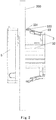
Fig.2 is a side view of the fiber optic splicing assembly ofFig.1 , wherein the fiber optic splicing assembly is mounted to a mounting wall and is not fixed to the mounting wall, and a reel thereof is in a retraction state; -
Fig.3 is a perspective view of the fiber optic splicing assembly ofFig.2 when viewing from a rear side of the mounting wall; -
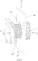
Fig.4 is a perspective view of the fiber optic splicing assembly ofFig.2 when viewing from a front side of the mounting wall; -
Fig.5 is a perspective view of the fiber optic splicing assembly ofFig.4 when a cover is removed; -
Fig.6 is a side view of the fiber optic splicing assembly ofFig.1 , wherein the fiber optic splicing assembly is mounted to a mounting wall, and a reel of it is in an expansion state; -
Fig.7 is a perspective view of the fiber optic splicing assembly ofFig.6 when viewing from a rear side of the mounting wall; -
Fig.8 is a perspective view of a bracket of the fiber optic splicing assembly of the present invention when viewing in a direction; -
Fig.9 is a perspective view of the bracket of the fiber optic splicing assembly of the present invention when viewing in another direction; -
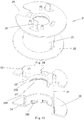
Fig.10 is a perspective view of a reel of the fiber optic splicing assembly of the present invention; -
Fig.11 is a cross section view of the reel shown inFig.10 ; -
Fig.12 is a perspective view of an intermediate shaft of the fiber optic splicing assembly of the present invention; -
Fig.13 is a cross section view of the intermediate shaft shown inFig.12 ; -
Fig.14 is a cross section view of the fiber optic splicing assembly ofFig.4 taken in a line A-A according to the present invention; -
Fig.15 is a cross section view of the fiber optic splicing assembly ofFig.6 taken in a line B-B according to the present invention; -
Fig.16 is a cross section view of the fiber optic splicing assembly ofFig.6 taken in a line C-C according to the present invention; and -
Fig.17 is a cross section view of the fiber optic splicing assembly ofFig.6 taken in a line D-D according to the present invention. - Exemplary embodiments of the present disclosure will be described hereinafter in detail with reference to the attached drawings, wherein the like reference numerals refer to the like elements. The present disclosure may, however, be embodied in many different forms and should not be construed as being limited to the embodiment set forth herein; rather, these embodiments are provided so that the present disclosure will be thorough and complete, and will fully convey the concept of the disclosure to those skilled in the art.
-
Fig.1 is an exploded view of a fiberoptic splicing assembly 100 according to an exemplary embodiment of the present invention. The fiberoptic splicing assembly 100 may be applied to splice fibers of different optical cables according to a general invention concept. - As shown in
Fig.1 , the fiberoptic splicing assembly 100 of the present invention may be mounted to a mountingwall 200 with a mounting hole 201 (please refer toFig.6 ). The fiberoptic splicing assembly 100 mainly comprises asplicing panel 1 and afiber storing device 10. - As shown in
Fig.1 andFig.5 , thesplicing panel 1 may be constructed as a conventional splicing panel. In the illustrated embodiment ofFig.1 , thesplicing panel 1 comprises a fiber optic splicing device 11 for splicing fibers, a mounting assembly for mounting the fiber optic splicing device 11, and astoring device 12 for storing a redundant fiber. Also, the fiberoptic splicing assembly 100 further comprises acover 5 covered on thesplicing panel 1. - As shown in
Figs. 1-7 , in a fiberoptic splicing assembly 100 according to an exemplary embodiment of the present invention, a rear side of thesplicing panel 1 is removably mounted on a front side of the mountingwall 200, and a front side of thesplicing panel 1 is configured to mount the fiber optic splicing device 11 for splicing fibers. Thefiber storing device 10 is configured to be at least partially received in the mountinghole 201, and one end of thefiber storing device 10 is removably mounted to thesplicing panel 1. - The
fiber storing device 10 comprises areel 2. Thereel 2 is removably mounted to the rear side of thesplicing panel 1. An optical cable and/or fiber to be spliced is pre-stored on thereel 2, for example, by winding. Thefiber storing device 10 further comprises abracket 3 on which thereel 2 is mounted. Thebracket 3 is configured to mount thefiber storing device 10 to the mountingwall 200, for example, on the rear side of the mountingwall 200. - The
bracket 3 comprises asupport shaft 31 having a free end (please refer toFig.9 ), and thereel 2 is movably sleeved onto thesupport shaft 31 so that thereel 2 can be axially moved relative to thesupport shaft 31 from a retraction state where thereel 2 is located in the mountinghole 201 to a expansion state where thereel 2 is exposed outside the mountinghole 201. When thereel 2 is in the expansion state, an operator can unreel the optical cable or fiber stored on thereel 2 from an outside of the mountingwall 200. Furthermore, thereel 2 is rotatably sleeved onto thesupport shaft 31 and is received in thebracket 3. - The
fiber storing device 10 of the fiberoptic splicing assembly 100 further comprises anintermediate shaft 4 having a first end movably connected to thereel 2 in an axial direction (that is, a direction in which thereel 2 is retracted and expanded) and a second end movably connected to thesupport shaft 31 in the axial direction. By adjusting the length of theintermediate shaft 4, the operator may pull thereel 2 to a position outside the mountingwall 200 where a redundant optical cable or fiber can be easily reeled on or unreeled from thereel 2. In an exemplary embodiment of the present invention, thereel 2 is configured to be capable of being moved through the mounting hole 201 (please refer toFig.6 ) from the rear side to the front side of the mountingwall 200 along thesupport shaft 31 so as to reach the expansion state. Theintermediate shaft 4 is engaged to thesupport shaft 31 in a manner of being axially movable, and the first end (a left end shown inFig.1 , or an upper end shown inFig.13 ) of theintermediate shaft 4 is rotatably engaged to thereel 2. - Also, the
intermediate shaft 4 is slidably engaged to thesupport shaft 31 in a profile matching manner, that is, theintermediate shaft 4 and thesupport shaft 31 have structures mated with each other in shape. In this way, it can prevent theintermediate shaft 4 from being rotated relative to thesupport shaft 31. - As shown in
Figs.1 ,12 and 13 , theintermediate shaft 4 has a substantially tube-like structure and is slidably sleeved onto thesupport shaft 31. Furthermore, a plurality of slide grooves extending in the axial direction are formed in one of an inner surface of theintermediate shaft 4 and an outer surface of thesupport shaft 31, and a plurality of slide protrusions for being slidably fitted in respective slide grooves are formed on the other of the inner surface of theintermediate shaft 4 and the outer surface of thesupport shaft 31. - In an exemplary embodiment of the present invention, the slide grooves are formed in the outer surface of the
support shaft 31, and the slide protrusions are formed in the inner surface of theintermediate shaft 4 adjacent to the first end (a lower end shown inFig.13 ). In this way, theintermediate shaft 4 can be slid in the axial direction with the slide protrusions fitted in the respective slide grooves of thesupport shaft 31, and cannot be rotated relative to thesupport shaft 31 because of the blocking function of the slide protrusions. It should be appreciated that, in an alternative embodiment, the slide protrusions may be formed in the outer surface of thesupport shaft 31, and the slide grooves may be formed in the inner surface of theintermediate shaft 4 adjacent to the first end. - Further, please refer to
Figs.6 ,8, 9 ,12-13 and15-16 , the slide grooves formed in thesupport shaft 31 comprise at least onefirst slide groove 311 and at least onesecond slide groove 316, and the slide protrusions formed on the inner surface of theintermediate shaft 4 comprise at least onefirst slide protrusion 42 and at least onesecond slide protrusion 43. During converting thereel 2 from the retraction state to the expansion state or from the expansion state to the retraction state, thefirst slide protrusion 42 and thesecond slide protrusion 43 are slid in thefirst slide groove 311 and thesecond slide groove 316, respectively, and block theintermediate shaft 4 from being rotated relative to thesupport shaft 31. Thefirst slide groove 311 is provided with afirst block projection 312 at a position adjacent to the free end (a tip end) of thesupport shaft 31, and thesecond slide groove 316 is provided with afirst limit projection 313 at a position adjacent to the free end of thesupport shaft 31. In this way, when thereel 2 is converted from the retraction state to the expansion state in a first slide direction (an upward direction ofFigs. 15 and16 ), thefirst block projection 312 is locked with the first slide protrusion 42 (Fig. 15 ) to block theintermediate shaft 4 from being disengaged from the free end of thesupport shaft 31, and thefirst limit projection 313 is snapped with the second slide protrusion 43 (Fig. 16 ) to limit theintermediate shaft 4 from being slid in a second slide direction (a downward direction ofFig.16 ) opposite to the first slide direction. - Referring to
Figs. 13 and15 , thefirst block projection 312 and thefirst limit projection 313 each has a matching surface substantially perpendicular to the axial direction, therefore, once thefirst block projection 312 is matched with thefirst slide protrusion 42 by sliding theintermediate shaft 4, theintermediate shaft 4 cannot be further moved forward regardless of an force exerted on it unless a matching structure of thefirst block projection 312 and thefirst slide protrusion 42 is broken. That is, thefirst block projection 312 is matched with thefirst slide protrusion 42 in a lock-fit manner. - As shown in
Figs. 13 and16 , thefirst limit projection 313 and thesecond slide protrusion 43 each has a matching surface inclined to the axial direction, therefore, during sliding theintermediate shaft 4 from the retraction state to the expansion state, a relative large force is exerted on it in the first slide direction so that thesecond slide protrusion 43 can slide across thefirst limit projection 313 due to a flexible deformation of thesecond slide protrusion 43 and then position theintermediate shaft 4 in the expansion state. Thereafter, when the force is removed, thefirst limit projection 313 limits thesecond slide protrusion 43 from being moved in the second slide direction (a downward direction ofFig.16 ) opposite to the first slide direction. But it is appreciated that the limitation of thefirst limit projection 313 to thesecond slide protrusion 43 can be released and that theintermediate shaft 4 can be moved downward as shown inFig.16 when a relative large force is exerted on theintermediate shaft 4 in the second slide direction. That is, thefirst limit projection 313 is matched with thesecond slide protrusion 43 in a snap-fit manner. - Although it has been described that the first and
second slide protrusions reel 2 is converted from the retraction state to the expansion state in a first slide direction, the first block projection is locked with the slide protrusion to block the intermediate shaft from being disengaged from the free end, and the first limit projection is snapped with the slide protrusion to limit the intermediate shaft from being slid in a second slide direction opposite to the first slide direction. - In a fiber
optic splicing assembly 100 according to a further embodiment of the present invention, please refer toFigs. 10 and 11 , thereel 2 comprises acylindrical body 21 andflanges 22 formed at both ends of thecylindrical body 21. Anotch 26 is formed in theflange 22 for the optical cable or fiber passing therethrough. The first end (an upper end ofFigs.12 and 13 ) of theintermediate shaft 4 is engaged into thecylindrical body 21 of thereel 2 in a manner of being axially movable. - Please refer to
Fig.17 , thecylindrical body 21 is provided with aring protrusion 24 inside a first end (a lower end ofFigs. 10 and 11 ) of thecylindrical body 21, thering protrusion 24 is rotatably fitted with the outer surface of theintermediate shaft 4 adjacent to the first end of theintermediate shaft 4. - As shown in
Figs. 10-11 and14 , anengagement portion 25 is formed on and extended from thecylindrical body 21 of thereel 2 for fixing thereel 2 to thesplicing panel 1 in a snap-in manner. - Further, referring to
Figs. 12-13 and15-16 again, a plurality ofsecond block projections 44 are provided on the first end (an upper end inFigs. 12, 13 ) of theintermediate shaft 4, and thesecond block projections 44 are configured to lock with aside edge 241 of thering protrusion 24 far away from the first end (a lower end inFigs. 10, 11 ) of thecylindrical body 21 so as to block thereel 2 from being disengaged from the first end of theintermediate shaft 4 when thereel 2 is in the expansion state. Thesecond block projections 44 and theside edge 241 each has a matching surface substantially perpendicular to the axial direction. - On the other hand, a plurality of
second limit projections 242 are provided on thering protrusion 24, and aring groove 45 is formed in the outer surface of theintermediate shaft 4. When thereel 2 is converted from the retraction state to the expansion state in the first slide direction, thesecond limit projection 242 is snapped with thering groove 45 so as to limit theintermediate shaft 4 from being slid in the second slide direction opposite to the first slide direction. - Furthermore, referring to
Figs.10-11 and14 , aring skirt portion 23 is provided inside a second end (an upper end inFigs. 10, 11 ) of thecylindrical body 21, and there is agap 232 between thering skirt portion 23 and an inner wall of thecylindrical body 21. When thereel 2 is in the retraction state, thering skirt portion 23 is located between the second end of theintermediate shaft 4 and the free end of the support shaft 31 (as shown inFig. 14 ), so that thereel 2 can be rotated relative to thesupport shaft 31 and theintermediate shaft 4. - A
ring limit projection 231 is formed on thering skirt portion 23, and a third limit projection 315 (referring toFig.9 ) is provided on the free end of thesupport shaft 31. Thering limit projection 231 is snapped with thethird limit projection 315 so as to limit thereel 2 from being moved far away from theintermediate shaft 4 when thereel 2 is in the retraction state. In this way, thereel 2 can be stably received in thebracket 3. - In a fiber
optic splicing assembly 100 according to a further embodiment of the present invention, thebracket 3 comprises abase 35 and a plurality ofsupport arms 32. Thesupport shaft 31 is supported on thebase 35. A plurality ofsupport arms 32 extend from an edge of thebase 35. Thebracket 3 is mounted to the mountingwall 200 by means of thesupport arms 32. Furthermore, a free end of thesupport arm 32 is provided with aflange 34 which is capable of being engaged to a front side of the mountingwall 200. Theflange 34 is provided with a plurality offixation pin 341 which are capable of being inserted into the mountingwall 200. Thebracket 3 further comprises a plurality of groups ofpositioning devices 33 extending from an edge of thebase 35, and thepositioning devices 33 and thesupport arms 32 are arranged alternately. Each group ofpositioning devices 33 comprises a plurality of positioningelastic sheets 331 having different length with each other. Also, the positioningelastic sheet 331 is provided with apositioning projection 332. In this way, please refer toFigs.3 and7 , when the fiberoptic splicing assembly 100 of the present invention is mounted on the mountingwall 200, the fiberoptic splicing assembly 100 is forced to pass through the mountinghole 201 from the front side of the mountingwall 200 to the rear side of the mountingwall 200, or thesupport arms 32 are slightly contracted inwardly to pass through the mountinghole 201 from the rear side of the mountingwall 200 to the front side of the mountingwall 200, and theflange 34 is fixed onto the front side of the mounting wall 20 with thefixation pin 341 of theflange 34. At the same time, the positioningelastic sheets 331 of thepositioning devices 33 are abut against the rear side of the mountingwall 200. If the mountingwall 200 has a large thickness, the positioningelastic sheets 331 having a larger length are inserted into the mountinghole 201, and thepositioning projections 332 of the positioningelastic sheets 331 are abut against the rear side of the mounting 200, so that thebracket 3 can be reliably mounted on the mountingwall 200. - In an alternative embodiment of the present invention, the
support arm 32 is elastic, and a circumference formed by thesupport arms 32 has an outer diameter larger than a diameter of the mountinghole 201. When thesupport arms 32 are mounted into the mountinghole 201, the support arms are elastically deformed and exert an elastic stress on the mountinghole 201 to fix thesupport arms 32 in the mountinghole 201. - As shown in
Figs.9 and14 , in a further exemplary embodiment of the present invention, thebase 35 is provided with a plurality ofelastic pieces 36 inwardly protruded. As shown inFigs.2 and5 , twoinstallation holes 14 are formed in thesplicing panel 1. When thereel 2 is received in thebracket 3 and when thesplicing panel 1 is not fixed to the mountingwall 200 yet, thereel 2 is still relatable relative to thesupport shaft 31. During rotating thereel 2, the rear side of thesplicing panel 1 is separated from the front side of the mountingwall 200 by a certain distance by means of theelastic pieces 36. Accordingly, it can prevent the surface of the mountingwall 200 from being scraped by thesplicing panel 1 during rotating thesplicing panel 1, while ensuring the stable rotation of thesplicing panel 1. Thesplicing panel 1 is provided with at least twoinstallation holes 14 for fixing thesplicing panel 1 on the mountingwall 200 in cooperation with screws (not shown). After thesplicing panel 1 is mounted on the mountingwall 200 by means of the installation holes 14, as shown inFigs.3-5 , by screwing the screws, theelastic pieces 36 are compressed, and the gap between the rear side of thesplicing panel 1 and the front side of the mountingwall 200 can be eliminated, so that thesplicing panel 1 is reliably mounted on the mountingwall 200. - Although it has been described that the
intermediate shaft 4 is not rotatable relative to thesupport shaft 31 and that thereel 2 is rotatable relative to theintermediate shaft 4 in the above embodiments, the present invention is not limited to this. In a fiber optic splicing assembly according to another exemplary embodiment of the present invention, the intermediate shaft has a first end which is rotatably and axial-slideably connected to the support shaft and a second end which is axial-movably connected to the reel and not rotated with respect to the reel. - In a further alternative exemplary embodiment, the reel may be directly slidably connected to the support shaft. For example, a plurality of slide grooves extending in the axial direction are formed in one of an inner surface of the reel and an outer surface of the support shaft, and a plurality of slide protrusions for being slidably fitted in respective slide grooves are formed on the other of the inner surface of the reel and the outer surface of the support shaft.
- In the fiber optic splicing assembly described in the above embodiments, the reel may be retracted to the rear side of the mounting wall and expanded to the front side of the mounting wall, facilitating the maintenance and management operation on the redundant optical cable and/or fiber. During mounting the splicing panel, the optical cable or fiber may be pre-stored in the reel. The optical cable or fiber may be unreeled out of the reel in use and spliced to other devices without calculating the length of the optical cable or fiber to be used, thereby achieving a quick splicing operation. The bracket for receiving the reel may be mounted on various mounting walls, for example, plasterboards, with different thicknesses. Also, the reel is still rotatable in the bracket under the retraction state where it is received in the bracket. In addition, the reel is rotatable relative to the support shaft under the expansion state where it is expanded out of the bracket to the front side of the mounting wall, so that the optical cable or fiber can be unreeled from the reel. Furthermore, in the retraction state, the reel and the bracket both are mounted on the rear side of the mounting wall, and only the splicing panel having a thinner thickness is protruded outside the front side of the mounting wall, saving the space and having a good appearance.
- It should be appreciated for those skilled in this art that the above embodiments are intended to be illustrated, and not restrictive. For example, many modifications may be made to the above embodiments by those skilled in this art, and various features described in different embodiments may be freely combined with each other without conflicting in configuration or principle, so that more kinds of fiber optic splicing assemblies can be achieved with overcoming the technical problem of the present invention.
- As used herein, an element recited in the singular and proceeded with the word "a" or "an" should be understood as not excluding plural of said elements or steps, unless such exclusion is explicitly stated. Furthermore, references to "one embodiment" of the present invention are not intended to be interpreted as excluding the existence of additional embodiments that also incorporate the recited features. Moreover, unless explicitly stated to the contrary, embodiments "comprising" or "having" an element or a plurality of elements having a particular property may include additional such elements not having that property.
Claims (15)
- A fiber optic splicing assembly (100) mountable to a mounting wall (200) with a mounting hole (201), comprising:a splicing panel (1) of which a front side is configured to mount a fiber optic splicing device (11) for splicing fibers;a fiber storing device (10) configured to be at least partially received in the mounting hole,wherein the fiber storing device (10) comprises a bracket (3) mountable to the mounting wall (200) and a reel (2) for pre-storing an optical cable and/or fiber, said reel (2) being mounted on the bracket (3) and being removably mounted to a rear side of the splicing panel (1), wherein the bracket (3) comprises a support shaft (31), and the reel (2) is movably sleeved onto the support shaft (31) so that the reel (2) is axially movable relative to the support shaft (31) from a retraction state where the reel (2) is located in the mounting hole (201) to a expansion state where the reel (2) is exposed outside the mounting hole (201); and wherein when the reel (2) is in the expansion state, an operator can unreel the optical cable or fiber stored on the reel (2) from an outside of the mounting wall (200).
- The fiber optic splicing assembly according to claim 1, wherein the reel (2) is rotatably sleeved onto the support shaft (31).
- The fiber optic splicing assembly according to claim 2,
wherein the fiber storing device (10) further comprises an intermediate shaft (4) having a first end connected to the reel (2) in a manner of being axially movable and a second end connected to the support shaft (31) in a manner of being axially movable, or having a first end connected to the support shaft in a manner of rotatable and axially slideable and a second end connected to the reel in a manner of axially movable. - The fiber optic splicing assembly according to claim 3,
wherein the reel (2) is rotatably engaged to the first end of the intermediate shaft (4). - The fiber optic splicing assembly according to claim 4, whereina) the intermediate shaft (4) is slidably engaged to the support shaft (31) in a profile matching manner so as to prevent the intermediate shaft (4) from being rotated relative to the support shaft (31); orb) the intermediate shaft (4) has a substantially tube-like structure and is slidably sleeved onto the support shaft (31); orc) the first end of the intermediate shaft (4) is engaged into a cylindrical body of the reel (2) in a manner of being axially movable.
- The fiber optic splicing assembly according to claim 5, item b),
wherein a plurality of slide grooves extending in an axial direction are formed in one of an inner surface of the intermediate shaft (4) and an outer surface of the support shaft (31); and
wherein a plurality of slide protrusions for being slidably fitted in respective slide grooves are formed on the other of the inner surface of the intermediate shaft (4) and the outer surface of the support shaft (31). - The fiber optic splicing assembly according to claim 6,
wherein the slide grooves are formed in the outer surface of the support shaft (31), and the slide protrusions are formed in the inner surface of the intermediate shaft (4) adjacent to the first end; and wherein preferably:- the slide groove is provided with a first block projection (312) and a first limit projection (313) at a position adjacent to a free end of the support shaft; and wherein when the reel (2) is converted from the retraction state to the expansion state in a first slide direction, the first block projection (312) is locked with the slide protrusion to block the intermediate shaft (4) from being disengaged from the free end, and the first limit projection (313) is snapped with the slide protrusion to limit the intermediate shaft (4) from sliding in a second slide direction opposite to the first slide direction; or- the slide grooves comprise at least one first slide groove and at least one second slide groove, and the slide protrusions comprise at least one first slide protrusion and at least one second slide protrusion; wherein the first slide groove is provided with a first block projection at a position adjacent to a free end of the support shaft, and the second slide groove is provided with a first limit projection at a position adjacent to the free end of the support shaft; and wherein when the reel (2) is converted from the retraction state to the expansion state in a first slide direction, the first block projection (312) is locked with the first slide protrusion to block the intermediate shaft (4) from being disengaged from the free end, and the first limit projection (313) is snapped with the second slide protrusion to limit the intermediate shaft (4) from sliding in a second slide direction opposite to the first slide direction. - The fiber optic splicing assembly according to claim 5, item c,
wherein the cylindrical body is provided with a ring protrusion (24) inside a first end thereof, and
wherein the ring protrusion is rotatably fitted with the outer surface of the intermediate shaft adjacent to the first end of the intermediate shaft. - The fiber optic splicing assembly according to claim 8,
wherein a plurality of second block projections are provided on the first end of the intermediate shaft, and the second block projection is configured to lock with a side edge of the ring protrusion far away from the first end of the cylindrical body so as to block the reel from being disengaged from the first end of the intermediate shaft when the reel is converted from the retraction state to the expansion state. - The fiber optic splicing assembly according to claim 9, whereina) a plurality of second limit projections are provided on the ring protrusion, and a ring groove is formed in the outer surface of the intermediate shaft, and wherein the second limit projection is configured to snap with the ring groove so as to limit the intermediate shaft from slide in a second slide direction opposite to a first slide direction when the reel is converted from the retraction state to the expansion state in the first slide direction; and/orb) a ring skirt portion is provided inside a second end of the cylindrical body, and a gap is formed between the ring skirt portion and an inner wall of the cylindrical body; and wherein when the reel is in the retraction state, the ring skirt portion is located between the second end of the intermediate shaft and the free end of the support shaft, so that the reel is rotatable relative to the support shaft and the intermediate shaft, and wherein preferably a ring limit projection is formed on the ring skirt portion, and a third limit projection is provided on the free end of the support shaft, and wherein preferably the ring limit projection is snapped with the third limit projection so as to limit the reel from being moved far away from the intermediate shaft when the reel is in the retraction state.
- The fiber optic splicing assembly according to claim 3, wherein the bracket comprises:a base on which the support shaft is supported, wherein the base is preferably provided with a plurality of elastic pieces inwardly protruded; anda plurality of support arms extending from an edge of the base,wherein the bracket is mounted to the mounting wall by means of the support arms.
- The fiber optic splicing assembly according to claim 11, wherein:- a free end of the support arm is provided with a flange capable of being engaged to a front side of the mounting wall, wherein the flange is preferably provided with a fixation pin capable of being inserted into the mounting wall; and/or- wherein the support arm is elastic, and a circumference formed by the support arms has an outer diameter larger than a diameter of the mounting hole; and wherein when the support arms are mounted into the mounting hole, the support arms are elastically deformed and exert an elastic stress on the mounting hole to fix the support arms in the mounting hole.
- The fiber optic splicing assembly according to claim 11 or 12,
wherein the bracket further comprises a plurality of groups of positioning devices extending from an edge of the support arms, and
wherein the positioning devices and the support arms are arranged alternately,
wherein preferably each group of positioning devices comprises a plurality of positioning elastic sheets having different length with each other, and
wherein most preferably the positioning elastic sheet is provided with a positioning projection. - The fiber optic splicing assembly according to claim 1,
wherein a plurality of slide grooves extending in an axial direction are formed in one of an inner surface of the reel and an outer surface of the support shaft; and
wherein a plurality of slide protrusions for being slidably fitted in respective slide grooves are formed on the other of the inner surface of the reel and the outer surface of the support shaft, and
wherein preferably a plurality of slide grooves extending in an axial direction are formed in one of an outer surface of the reel and an inner surface of the support shaft; and
wherein preferably a plurality of slide protrusions for being slidably fitted in respective slide grooves are formed on the other of the outer surface of the reel and the inner surface of the support shaft. - The fiber optic splicing assembly according to claim 1,
wherein the bracket is further formed with an engagement portion fixed to the splicing panel in a snap-fit manner.
Applications Claiming Priority (2)
| Application Number | Priority Date | Filing Date | Title |
|---|---|---|---|
| CN201210280488.9A CN103576266B (en) | 2012-08-07 | 2012-08-07 | Fiber optic connector |
| PCT/IB2013/056339 WO2014024105A1 (en) | 2012-08-07 | 2013-08-02 | Fiber optic splicing assembly |
Publications (2)
| Publication Number | Publication Date |
|---|---|
| EP2883100A1 EP2883100A1 (en) | 2015-06-17 |
| EP2883100B1 true EP2883100B1 (en) | 2019-05-01 |
Family
ID=49223832
Family Applications (1)
| Application Number | Title | Priority Date | Filing Date |
|---|---|---|---|
| EP13765517.1A Active EP2883100B1 (en) | 2012-08-07 | 2013-08-02 | Fiber optic splicing assembly |
Country Status (7)
| Country | Link |
|---|---|
| US (1) | US9594217B2 (en) |
| EP (1) | EP2883100B1 (en) |
| JP (1) | JP6313303B2 (en) |
| CN (2) | CN106707434B (en) |
| AU (1) | AU2013301184B2 (en) |
| NZ (1) | NZ705741A (en) |
| WO (1) | WO2014024105A1 (en) |
Families Citing this family (10)
| Publication number | Priority date | Publication date | Assignee | Title |
|---|---|---|---|---|
| US9835814B2 (en) | 2013-11-06 | 2017-12-05 | Adc Czech Republic S.R.O. | Fiber termination point with overlength storage |
| US10754115B2 (en) | 2015-04-22 | 2020-08-25 | CommScope Connectivity Belgium BVBA | Deploying optical fibers within a multi-dwelling unit |
| AU2016297602B2 (en) | 2015-07-23 | 2020-12-17 | Commscope Technologies Llc | Cable spool re-orientation device for a wall box |
| US10162143B1 (en) * | 2017-09-21 | 2018-12-25 | Ofs Fitel, Llc | Behind-the-wall fiber spool module |
| DE102019106951A1 (en) * | 2019-03-19 | 2020-09-24 | Wilhelm Rutenbeck Gmbh & Co. Kg | Device for receiving and securely holding the wires of an optical fiber |
| CN111722335B (en) * | 2020-06-09 | 2022-09-23 | 华为技术有限公司 | Optical cable storage device |
| CN113566868A (en) * | 2021-08-27 | 2021-10-29 | 国网浙江省电力有限公司信息通信分公司 | Connection box intelligent monitoring device |
| WO2023097582A1 (en) * | 2021-12-01 | 2023-06-08 | 山东微感光电子有限公司 | Distributed optical fiber temperature measurement device, and photovoltaic panel temperature measurement system and method |
| IT202400011113A1 (en) | 2024-05-16 | 2025-11-16 | Prysmian Spa | A FIBER OPTIC STORAGE DEVICE |
| IT202400011119A1 (en) | 2024-05-16 | 2025-11-16 | Prysmian Spa | A FIBER OPTIC STORAGE DEVICE |
Family Cites Families (12)
| Publication number | Priority date | Publication date | Assignee | Title |
|---|---|---|---|---|
| US6591053B2 (en) * | 2000-03-08 | 2003-07-08 | Panduit Corp. | Fiber optic wall mount cabinet |
| JP4213367B2 (en) * | 2001-06-20 | 2009-01-21 | 株式会社フジクラ | Optical component module |
| JP2004303629A (en) * | 2003-03-31 | 2004-10-28 | Daiwa House Ind Co Ltd | Structure of embedded type outlet |
| JP2005024978A (en) * | 2003-07-03 | 2005-01-27 | Mirai Ind Co Ltd | Cable lead-out structure, cable lead-out forming device, winding member, mounting frame and plate |
| US20080011514A1 (en) * | 2006-07-14 | 2008-01-17 | Tenvera, Inc. | Optical Fiber Distribution Apparatus and Method |
| CN101221270B (en) * | 2007-01-13 | 2012-01-11 | 古河电子北美公司 | Wall-mountable optical fiber and cable management apparatus |
| US7715679B2 (en) * | 2007-05-07 | 2010-05-11 | Adc Telecommunications, Inc. | Fiber optic enclosure with external cable spool |
| US7748660B2 (en) * | 2007-06-22 | 2010-07-06 | Ofs Fitel, Llc | Fiber optic rapid spooling tool |
| US7756379B2 (en) * | 2007-08-06 | 2010-07-13 | Adc Telecommunications, Inc. | Fiber optic enclosure with internal cable spool |
| US8265447B2 (en) * | 2008-09-16 | 2012-09-11 | Adc Telecommunications, Inc. | Modular fiber optic enclosure with external cable spool |
| CN202583564U (en) * | 2012-05-03 | 2012-12-05 | 泰科电子(上海)有限公司 | Optical fiber splice box |
| CN202837598U (en) * | 2012-08-07 | 2013-03-27 | 泰科电子(上海)有限公司 | Optical fiber connection assembly |
-
2012
- 2012-08-07 CN CN201611163812.3A patent/CN106707434B/en not_active Expired - Fee Related
- 2012-08-07 CN CN201210280488.9A patent/CN103576266B/en not_active Expired - Fee Related
-
2013
- 2013-08-02 EP EP13765517.1A patent/EP2883100B1/en active Active
- 2013-08-02 AU AU2013301184A patent/AU2013301184B2/en active Active
- 2013-08-02 WO PCT/IB2013/056339 patent/WO2014024105A1/en not_active Ceased
- 2013-08-02 NZ NZ705741A patent/NZ705741A/en not_active IP Right Cessation
- 2013-08-02 JP JP2015525984A patent/JP6313303B2/en active Active
-
2015
- 2015-02-06 US US14/616,198 patent/US9594217B2/en active Active
Non-Patent Citations (1)
| Title |
|---|
| None * |
Also Published As
| Publication number | Publication date |
|---|---|
| CN106707434A (en) | 2017-05-24 |
| JP2015525907A (en) | 2015-09-07 |
| US9594217B2 (en) | 2017-03-14 |
| WO2014024105A1 (en) | 2014-02-13 |
| EP2883100A1 (en) | 2015-06-17 |
| CN106707434B (en) | 2019-06-11 |
| AU2013301184A1 (en) | 2015-03-26 |
| US20150153513A1 (en) | 2015-06-04 |
| NZ705741A (en) | 2017-04-28 |
| JP6313303B2 (en) | 2018-04-18 |
| AU2013301184B2 (en) | 2016-12-22 |
| CN103576266B (en) | 2017-01-18 |
| CN103576266A (en) | 2014-02-12 |
Similar Documents
| Publication | Publication Date | Title |
|---|---|---|
| AU2013301184B2 (en) | Fiber optic splicing assembly | |
| US11899260B2 (en) | Fiber optic cable deployment assemblies, systems, and methods | |
| USRE49385E1 (en) | Fiber optic cable distribution box | |
| EP3286589B1 (en) | Cable storage arrangement | |
| EP2176696B1 (en) | Fiber optic enclosure with internal cable spool | |
| EP3460552B1 (en) | Behind-the-wall fiber spool module | |
| US11231557B2 (en) | Cable spool re-orientation device for a wall box | |
| EP3445694A1 (en) | Retractable fiber optic reel assembly | |
| CN202837598U (en) | Optical fiber connection assembly | |
| EP4650841A1 (en) | A fiber optical storage equipment | |
| EP4650840A1 (en) | A fiber optical storage equipment | |
| CN224105316U (en) | Cable storage structure, panel structure and cable drum | |
| HK1121238B (en) | Wall-mountable optical fiber and cable management apparatus |
Legal Events
| Date | Code | Title | Description |
|---|---|---|---|
| PUAI | Public reference made under article 153(3) epc to a published international application that has entered the european phase |
Free format text: ORIGINAL CODE: 0009012 |
|
| 17P | Request for examination filed |
Effective date: 20150309 |
|
| AK | Designated contracting states |
Kind code of ref document: A1 Designated state(s): AL AT BE BG CH CY CZ DE DK EE ES FI FR GB GR HR HU IE IS IT LI LT LU LV MC MK MT NL NO PL PT RO RS SE SI SK SM TR |
|
| AX | Request for extension of the european patent |
Extension state: BA ME |
|
| RIN1 | Information on inventor provided before grant (corrected) |
Inventor name: XIAO, TELLER Inventor name: HUBBARD, PAUL Inventor name: WANG, LIMING Inventor name: YANG, YANHONG |
|
| DAX | Request for extension of the european patent (deleted) | ||
| RAP1 | Party data changed (applicant data changed or rights of an application transferred) |
Owner name: TYCO ELECTRONICS (SHANGHAI) CO., LTD. Owner name: ADC COMMUNICATIONS (AUSTRALIA) PTY. LIMITED |
|
| RAP1 | Party data changed (applicant data changed or rights of an application transferred) |
Owner name: ADC COMMUNICATIONS (AUSTRALIA) PTY. LIMITED Owner name: ADC TELECOMMUNICATIONS (SHANGHAI) DISTRIBUTION CO. |
|
| GRAP | Despatch of communication of intention to grant a patent |
Free format text: ORIGINAL CODE: EPIDOSNIGR1 |
|
| STAA | Information on the status of an ep patent application or granted ep patent |
Free format text: STATUS: GRANT OF PATENT IS INTENDED |
|
| INTG | Intention to grant announced |
Effective date: 20180703 |
|
| GRAJ | Information related to disapproval of communication of intention to grant by the applicant or resumption of examination proceedings by the epo deleted |
Free format text: ORIGINAL CODE: EPIDOSDIGR1 |
|
| STAA | Information on the status of an ep patent application or granted ep patent |
Free format text: STATUS: REQUEST FOR EXAMINATION WAS MADE |
|
| INTC | Intention to grant announced (deleted) | ||
| GRAP | Despatch of communication of intention to grant a patent |
Free format text: ORIGINAL CODE: EPIDOSNIGR1 |
|
| STAA | Information on the status of an ep patent application or granted ep patent |
Free format text: STATUS: GRANT OF PATENT IS INTENDED |
|
| INTG | Intention to grant announced |
Effective date: 20181122 |
|
| GRAS | Grant fee paid |
Free format text: ORIGINAL CODE: EPIDOSNIGR3 |
|
| GRAA | (expected) grant |
Free format text: ORIGINAL CODE: 0009210 |
|
| STAA | Information on the status of an ep patent application or granted ep patent |
Free format text: STATUS: THE PATENT HAS BEEN GRANTED |
|
| AK | Designated contracting states |
Kind code of ref document: B1 Designated state(s): AL AT BE BG CH CY CZ DE DK EE ES FI FR GB GR HR HU IE IS IT LI LT LU LV MC MK MT NL NO PL PT RO RS SE SI SK SM TR |
|
| REG | Reference to a national code |
Ref country code: GB Ref legal event code: FG4D |
|
| REG | Reference to a national code |
Ref country code: CH Ref legal event code: EP Ref country code: AT Ref legal event code: REF Ref document number: 1127696 Country of ref document: AT Kind code of ref document: T Effective date: 20190515 |
|
| REG | Reference to a national code |
Ref country code: DE Ref legal event code: R096 Ref document number: 602013054677 Country of ref document: DE |
|
| REG | Reference to a national code |
Ref country code: IE Ref legal event code: FG4D |
|
| REG | Reference to a national code |
Ref country code: NL Ref legal event code: MP Effective date: 20190501 |
|
| REG | Reference to a national code |
Ref country code: LT Ref legal event code: MG4D |
|
| PG25 | Lapsed in a contracting state [announced via postgrant information from national office to epo] |
Ref country code: FI Free format text: LAPSE BECAUSE OF FAILURE TO SUBMIT A TRANSLATION OF THE DESCRIPTION OR TO PAY THE FEE WITHIN THE PRESCRIBED TIME-LIMIT Effective date: 20190501 Ref country code: SE Free format text: LAPSE BECAUSE OF FAILURE TO SUBMIT A TRANSLATION OF THE DESCRIPTION OR TO PAY THE FEE WITHIN THE PRESCRIBED TIME-LIMIT Effective date: 20190501 Ref country code: AL Free format text: LAPSE BECAUSE OF FAILURE TO SUBMIT A TRANSLATION OF THE DESCRIPTION OR TO PAY THE FEE WITHIN THE PRESCRIBED TIME-LIMIT Effective date: 20190501 Ref country code: NO Free format text: LAPSE BECAUSE OF FAILURE TO SUBMIT A TRANSLATION OF THE DESCRIPTION OR TO PAY THE FEE WITHIN THE PRESCRIBED TIME-LIMIT Effective date: 20190801 Ref country code: PT Free format text: LAPSE BECAUSE OF FAILURE TO SUBMIT A TRANSLATION OF THE DESCRIPTION OR TO PAY THE FEE WITHIN THE PRESCRIBED TIME-LIMIT Effective date: 20190901 Ref country code: LT Free format text: LAPSE BECAUSE OF FAILURE TO SUBMIT A TRANSLATION OF THE DESCRIPTION OR TO PAY THE FEE WITHIN THE PRESCRIBED TIME-LIMIT Effective date: 20190501 Ref country code: HR Free format text: LAPSE BECAUSE OF FAILURE TO SUBMIT A TRANSLATION OF THE DESCRIPTION OR TO PAY THE FEE WITHIN THE PRESCRIBED TIME-LIMIT Effective date: 20190501 Ref country code: ES Free format text: LAPSE BECAUSE OF FAILURE TO SUBMIT A TRANSLATION OF THE DESCRIPTION OR TO PAY THE FEE WITHIN THE PRESCRIBED TIME-LIMIT Effective date: 20190501 Ref country code: NL Free format text: LAPSE BECAUSE OF FAILURE TO SUBMIT A TRANSLATION OF THE DESCRIPTION OR TO PAY THE FEE WITHIN THE PRESCRIBED TIME-LIMIT Effective date: 20190501 |
|
| PG25 | Lapsed in a contracting state [announced via postgrant information from national office to epo] |
Ref country code: LV Free format text: LAPSE BECAUSE OF FAILURE TO SUBMIT A TRANSLATION OF THE DESCRIPTION OR TO PAY THE FEE WITHIN THE PRESCRIBED TIME-LIMIT Effective date: 20190501 Ref country code: RS Free format text: LAPSE BECAUSE OF FAILURE TO SUBMIT A TRANSLATION OF THE DESCRIPTION OR TO PAY THE FEE WITHIN THE PRESCRIBED TIME-LIMIT Effective date: 20190501 Ref country code: BG Free format text: LAPSE BECAUSE OF FAILURE TO SUBMIT A TRANSLATION OF THE DESCRIPTION OR TO PAY THE FEE WITHIN THE PRESCRIBED TIME-LIMIT Effective date: 20190801 Ref country code: GR Free format text: LAPSE BECAUSE OF FAILURE TO SUBMIT A TRANSLATION OF THE DESCRIPTION OR TO PAY THE FEE WITHIN THE PRESCRIBED TIME-LIMIT Effective date: 20190802 |
|
| REG | Reference to a national code |
Ref country code: AT Ref legal event code: MK05 Ref document number: 1127696 Country of ref document: AT Kind code of ref document: T Effective date: 20190501 |
|
| PG25 | Lapsed in a contracting state [announced via postgrant information from national office to epo] |
Ref country code: IS Free format text: LAPSE BECAUSE OF FAILURE TO SUBMIT A TRANSLATION OF THE DESCRIPTION OR TO PAY THE FEE WITHIN THE PRESCRIBED TIME-LIMIT Effective date: 20190901 |
|
| PG25 | Lapsed in a contracting state [announced via postgrant information from national office to epo] |
Ref country code: AT Free format text: LAPSE BECAUSE OF FAILURE TO SUBMIT A TRANSLATION OF THE DESCRIPTION OR TO PAY THE FEE WITHIN THE PRESCRIBED TIME-LIMIT Effective date: 20190501 Ref country code: SK Free format text: LAPSE BECAUSE OF FAILURE TO SUBMIT A TRANSLATION OF THE DESCRIPTION OR TO PAY THE FEE WITHIN THE PRESCRIBED TIME-LIMIT Effective date: 20190501 Ref country code: DK Free format text: LAPSE BECAUSE OF FAILURE TO SUBMIT A TRANSLATION OF THE DESCRIPTION OR TO PAY THE FEE WITHIN THE PRESCRIBED TIME-LIMIT Effective date: 20190501 Ref country code: EE Free format text: LAPSE BECAUSE OF FAILURE TO SUBMIT A TRANSLATION OF THE DESCRIPTION OR TO PAY THE FEE WITHIN THE PRESCRIBED TIME-LIMIT Effective date: 20190501 Ref country code: RO Free format text: LAPSE BECAUSE OF FAILURE TO SUBMIT A TRANSLATION OF THE DESCRIPTION OR TO PAY THE FEE WITHIN THE PRESCRIBED TIME-LIMIT Effective date: 20190501 Ref country code: CZ Free format text: LAPSE BECAUSE OF FAILURE TO SUBMIT A TRANSLATION OF THE DESCRIPTION OR TO PAY THE FEE WITHIN THE PRESCRIBED TIME-LIMIT Effective date: 20190501 |
|
| REG | Reference to a national code |
Ref country code: DE Ref legal event code: R097 Ref document number: 602013054677 Country of ref document: DE |
|
| PG25 | Lapsed in a contracting state [announced via postgrant information from national office to epo] |
Ref country code: SM Free format text: LAPSE BECAUSE OF FAILURE TO SUBMIT A TRANSLATION OF THE DESCRIPTION OR TO PAY THE FEE WITHIN THE PRESCRIBED TIME-LIMIT Effective date: 20190501 Ref country code: IT Free format text: LAPSE BECAUSE OF FAILURE TO SUBMIT A TRANSLATION OF THE DESCRIPTION OR TO PAY THE FEE WITHIN THE PRESCRIBED TIME-LIMIT Effective date: 20190501 |
|
| PLBE | No opposition filed within time limit |
Free format text: ORIGINAL CODE: 0009261 |
|
| STAA | Information on the status of an ep patent application or granted ep patent |
Free format text: STATUS: NO OPPOSITION FILED WITHIN TIME LIMIT |
|
| PG25 | Lapsed in a contracting state [announced via postgrant information from national office to epo] |
Ref country code: TR Free format text: LAPSE BECAUSE OF FAILURE TO SUBMIT A TRANSLATION OF THE DESCRIPTION OR TO PAY THE FEE WITHIN THE PRESCRIBED TIME-LIMIT Effective date: 20190501 |
|
| 26N | No opposition filed |
Effective date: 20200204 |
|
| PG25 | Lapsed in a contracting state [announced via postgrant information from national office to epo] |
Ref country code: PL Free format text: LAPSE BECAUSE OF FAILURE TO SUBMIT A TRANSLATION OF THE DESCRIPTION OR TO PAY THE FEE WITHIN THE PRESCRIBED TIME-LIMIT Effective date: 20190501 |
|
| PG25 | Lapsed in a contracting state [announced via postgrant information from national office to epo] |
Ref country code: SI Free format text: LAPSE BECAUSE OF FAILURE TO SUBMIT A TRANSLATION OF THE DESCRIPTION OR TO PAY THE FEE WITHIN THE PRESCRIBED TIME-LIMIT Effective date: 20190501 Ref country code: LU Free format text: LAPSE BECAUSE OF NON-PAYMENT OF DUE FEES Effective date: 20190802 Ref country code: LI Free format text: LAPSE BECAUSE OF NON-PAYMENT OF DUE FEES Effective date: 20190831 Ref country code: CH Free format text: LAPSE BECAUSE OF NON-PAYMENT OF DUE FEES Effective date: 20190831 Ref country code: MC Free format text: LAPSE BECAUSE OF FAILURE TO SUBMIT A TRANSLATION OF THE DESCRIPTION OR TO PAY THE FEE WITHIN THE PRESCRIBED TIME-LIMIT Effective date: 20190501 |
|
| REG | Reference to a national code |
Ref country code: BE Ref legal event code: MM Effective date: 20190831 |
|
| PG25 | Lapsed in a contracting state [announced via postgrant information from national office to epo] |
Ref country code: FR Free format text: LAPSE BECAUSE OF NON-PAYMENT OF DUE FEES Effective date: 20190831 Ref country code: IE Free format text: LAPSE BECAUSE OF NON-PAYMENT OF DUE FEES Effective date: 20190802 |
|
| PG25 | Lapsed in a contracting state [announced via postgrant information from national office to epo] |
Ref country code: BE Free format text: LAPSE BECAUSE OF NON-PAYMENT OF DUE FEES Effective date: 20190831 |
|
| PG25 | Lapsed in a contracting state [announced via postgrant information from national office to epo] |
Ref country code: CY Free format text: LAPSE BECAUSE OF FAILURE TO SUBMIT A TRANSLATION OF THE DESCRIPTION OR TO PAY THE FEE WITHIN THE PRESCRIBED TIME-LIMIT Effective date: 20190501 |
|
| PG25 | Lapsed in a contracting state [announced via postgrant information from national office to epo] |
Ref country code: HU Free format text: LAPSE BECAUSE OF FAILURE TO SUBMIT A TRANSLATION OF THE DESCRIPTION OR TO PAY THE FEE WITHIN THE PRESCRIBED TIME-LIMIT; INVALID AB INITIO Effective date: 20130802 Ref country code: MT Free format text: LAPSE BECAUSE OF FAILURE TO SUBMIT A TRANSLATION OF THE DESCRIPTION OR TO PAY THE FEE WITHIN THE PRESCRIBED TIME-LIMIT Effective date: 20190501 |
|
| PG25 | Lapsed in a contracting state [announced via postgrant information from national office to epo] |
Ref country code: MK Free format text: LAPSE BECAUSE OF FAILURE TO SUBMIT A TRANSLATION OF THE DESCRIPTION OR TO PAY THE FEE WITHIN THE PRESCRIBED TIME-LIMIT Effective date: 20190501 |
|
| PGFP | Annual fee paid to national office [announced via postgrant information from national office to epo] |
Ref country code: GB Payment date: 20220829 Year of fee payment: 10 |
|
| P01 | Opt-out of the competence of the unified patent court (upc) registered |
Effective date: 20230530 |
|
| GBPC | Gb: european patent ceased through non-payment of renewal fee |
Effective date: 20230802 |
|
| PG25 | Lapsed in a contracting state [announced via postgrant information from national office to epo] |
Ref country code: GB Free format text: LAPSE BECAUSE OF NON-PAYMENT OF DUE FEES Effective date: 20230802 |
|
| PG25 | Lapsed in a contracting state [announced via postgrant information from national office to epo] |
Ref country code: GB Free format text: LAPSE BECAUSE OF NON-PAYMENT OF DUE FEES Effective date: 20230802 |
|
| PGFP | Annual fee paid to national office [announced via postgrant information from national office to epo] |
Ref country code: DE Payment date: 20250827 Year of fee payment: 13 |