EP2883066B1 - Improved magnetic field control - Google Patents
Improved magnetic field control Download PDFInfo
- Publication number
- EP2883066B1 EP2883066B1 EP13827064.0A EP13827064A EP2883066B1 EP 2883066 B1 EP2883066 B1 EP 2883066B1 EP 13827064 A EP13827064 A EP 13827064A EP 2883066 B1 EP2883066 B1 EP 2883066B1
- Authority
- EP
- European Patent Office
- Prior art keywords
- magnetic field
- assembly according
- power supply
- supply unit
- error signal
- Prior art date
- Legal status (The legal status is an assumption and is not a legal conclusion. Google has not performed a legal analysis and makes no representation as to the accuracy of the status listed.)
- Active
Links
Images

Classifications
-
- H—ELECTRICITY
- H01—ELECTRIC ELEMENTS
- H01F—MAGNETS; INDUCTANCES; TRANSFORMERS; SELECTION OF MATERIALS FOR THEIR MAGNETIC PROPERTIES
- H01F6/00—Superconducting magnets; Superconducting coils
- H01F6/006—Supplying energising or de-energising current; Flux pumps
- H01F6/008—Electric circuit arrangements for energising superconductive electromagnets
-
- G—PHYSICS
- G01—MEASURING; TESTING
- G01R—MEASURING ELECTRIC VARIABLES; MEASURING MAGNETIC VARIABLES
- G01R33/00—Arrangements or instruments for measuring magnetic variables
- G01R33/0023—Electronic aspects, e.g. circuits for stimulation, evaluation, control; Treating the measured signals; calibration
- G01R33/0041—Electronic aspects, e.g. circuits for stimulation, evaluation, control; Treating the measured signals; calibration using feed-back or modulation techniques
-
- G—PHYSICS
- G01—MEASURING; TESTING
- G01R—MEASURING ELECTRIC VARIABLES; MEASURING MAGNETIC VARIABLES
- G01R33/00—Arrangements or instruments for measuring magnetic variables
- G01R33/02—Measuring direction or magnitude of magnetic fields or magnetic flux
- G01R33/035—Measuring direction or magnitude of magnetic fields or magnetic flux using superconductive devices
- G01R33/0354—SQUIDS
-
- G—PHYSICS
- G01—MEASURING; TESTING
- G01R—MEASURING ELECTRIC VARIABLES; MEASURING MAGNETIC VARIABLES
- G01R33/00—Arrangements or instruments for measuring magnetic variables
- G01R33/02—Measuring direction or magnitude of magnetic fields or magnetic flux
- G01R33/06—Measuring direction or magnitude of magnetic fields or magnetic flux using galvano-magnetic devices
- G01R33/07—Hall effect devices
-
- G—PHYSICS
- G01—MEASURING; TESTING
- G01R—MEASURING ELECTRIC VARIABLES; MEASURING MAGNETIC VARIABLES
- G01R33/00—Arrangements or instruments for measuring magnetic variables
- G01R33/02—Measuring direction or magnitude of magnetic fields or magnetic flux
- G01R33/06—Measuring direction or magnitude of magnetic fields or magnetic flux using galvano-magnetic devices
- G01R33/09—Magnetoresistive devices
- G01R33/093—Magnetoresistive devices using multilayer structures, e.g. giant magnetoresistance sensors
-
- G—PHYSICS
- G01—MEASURING; TESTING
- G01R—MEASURING ELECTRIC VARIABLES; MEASURING MAGNETIC VARIABLES
- G01R33/00—Arrangements or instruments for measuring magnetic variables
- G01R33/20—Arrangements or instruments for measuring magnetic variables involving magnetic resonance
- G01R33/24—Arrangements or instruments for measuring magnetic variables involving magnetic resonance for measuring direction or magnitude of magnetic fields or magnetic flux
-
- H—ELECTRICITY
- H01—ELECTRIC ELEMENTS
- H01F—MAGNETS; INDUCTANCES; TRANSFORMERS; SELECTION OF MATERIALS FOR THEIR MAGNETIC PROPERTIES
- H01F6/00—Superconducting magnets; Superconducting coils
- H01F6/06—Coils, e.g. winding, insulating, terminating or casing arrangements therefor
Definitions
- the invention relates to a superconducting circuit arranged to produce a stable and accurate magnetic field.
- the invention also relates to a method for generating a stable magnetic field and a method for stabilising a magnetic field.
- a magnetic field from a superconducting circuit may fluctuate or drift.
- One approach to minimise deviations and improve the stability of the field generated is to include a field measurement device to measure the magnetic field value and feedback an error signal to the power supply (PSU).
- PSU power supply
- a disadvantage of this method is a relatively low level of accuracy and stability since the resolution of the main current PSU, which has an output current of typically 50-1000A, is of the order of a few PPM and so provides a current output resolution of order 1mA and so the magnetic field cannot be controlled to an accuracy of better than a few PPM.
- Another disadvantage is that the reaction time of the power supply is damped due to the stabilising circuitry associated with the DC current transducers.
- An alternative approach is to include a passive, coupled, short-circuited inductor in the electrical circuit.
- the inductor opposes a change of the magnetic field within the magnet. This tends to dampen the change of the magnetic field and lower the magnetic field drift rate.
- this method merely slows the rate of magnetic field drift without actually correcting it.
- a separately driven 'shim' coil controlled by the error signal from the magnetic field measurement device may be provided.
- the 'shim' coil is typically a room temperature coil within the bore of the superconducting magnet, and can provide a small correction signal to control the magnetic field drift.
- a limitation is that the shim coil has a reduced response due to a low number of turns and therefore does not offer a sufficient amount of correction.
- JP 2008 020266 discloses a superconducting magnetic system comprising a main power source providing an alternating current to a main coil, a magnetic field measuring probe, and a drift compensator, which provides an auxiliary alternative current in an opposite direction to the fluctuations in the field measured by the probe in order to restore the magnetic field.
- JP 2002 313624 and US 6816046 describe similar systems to that described in JP 2008 020266 .
- the invention comprises an assembly for generating a stable magnetic field as defined in claim 1.
- the magnetic field measurement device produces an error signal based on the measured magnetic field value and a predetermined magnetic field value.
- the error signal is proportional to the difference between the measured magnetic field value and the predetermined magnetic field value.
- the field measurement device comprises a nuclear magnetic resonance (NMR) probe and a detection circuit.
- the field measurement device comprises a pick up coil which produces an error signal based on the rate of change of the magnetic field indicating the difference between the measured magnetic field and a predetermined magnetic field value.
- the field measurement device is a Hall effect sensor, giant magnetoresistance (GMR) sensor, or superconducting quantum interference device (SQUID) sensor.
- the error signal is conditioned by a PID function before it is input to the auxiliary power supply unit.
- the auxiliary power supply unit has a maximum output current of about +/-0.01 to about 1%, 0.01 to 0.5%, or 0.01 to 0.1% of the output current of the main current unit.
- the auxiliary power supply unit has a stability of better than 25 or better than 10 PPM (parts per million) per hour of its maximum output current.
- the superconducting magnetic circuit comprises a high temperature superconductor (HTS) coil.
- the superconducting magnetic circuit may comprise a low temperature superconductor (LTS) coil.
- the assembly further comprises a DC current transformer (DCCT) to control the main power supply unit.
- DCCT DC current transformer
- the invention comprises a method for generating a stable magnetic field as defined in claim 12.
- the term "comprising” as used in this specification and claims means “consisting at least in part of”. When interpreting each statement in this specification and claims that includes the term “comprising”, features other than that or those prefaced by the term may also be present. Related terms such as “comprise” and “comprises” are to be interpreted in the same manner.
- the invention relates to an assembly for generating a stable superconducting magnetic field.
- the assembly comprises a main magnetic power supply unit 1 across the input terminals of a coil assembly 2.
- the main magnetic power supply unit 1 aims to provide a main current, typically in the range of 50-1000 Amps to the magnet coil 2.
- the stability of this main current is typically in a range of a few PPM per hour (parts per million). It is to be understood that magnet coil 2 is subject to a number of factors which would cause the magnetic field generated to drift irrespective of the stability of the main input current. Some of these factors include flux redistribution within the superconductor and thermal drift due to small changes in the dimensions of the magnet created by environmental temperature changes. As a result, the magnetic field stability can be no better than the stability of the output current from the main power supply unit 1.
- Figure 1 also shows a field measurement device 3 and an auxiliary power supply unit 4.
- the field measurement device provides a measurement of the magnetic field present in the magnet 2 and generates an error signal proportional to the drift of the magnetic field away from some predetermined value. This error signal is then fed into the auxiliary power supply unit 4.
- the auxiliary power supply unit 4 is a low current, low voltage power supply unit which is connected in parallel with the main magnetic power supply unit 1.
- the auxiliary power supply unit 4 Upon receiving the error signal which represents the value of the drift, the auxiliary power supply unit 4 provides a correction current to the magnet coil 2 to correct for such a drift. This is shown in Figure 2 .
- the error signal generated by the field measurement device is conditioned by a PID function before it is supplied to the auxiliary power supply unit.
- the PID function parameters may be optimised to the measured drift rate of the magnet to allow for accurate field control with minimal field oscillations which may be added to the magnetic field by changing the error signal input to the auxiliary power supply unit too rapidly.
- the field measurement device comprises an NMR probe and a detection circuit. It may further comprise a magnetically coupled pick up coil which provides an error signal to the auxiliary power supply unit 4 in response to the rate of the magnetic field drift. It may alternatively comprise a Hall effect sensor, GMR sensor, or SQUID sensor.
- the auxiliary power supply unit provides a highly stable, but significantly lower current to the magnet 2.
- the auxiliary power supply unit may have a maximum output current of +/- about 0.01 to about 1%, or 0.01 to about 0.5%, or 0.01 to about 0.1% of the output current of the main current unit.
- the output current by the auxiliary power supply unit 4 is typically in the range of +/- 100 milli amps. Preferably this current is proportional to the error signal generated by the field measurement device 3 and has stability typically better than 25 or 10 PPM per hour of the maximum output current of the auxiliary power supply unit.
- the magnet coil 2 is fabricated using a high temperature superconductor (HTS). Alternatively it could be fabricated using a low temperature superconductor (LTS).
- HTS high temperature superconductor
- LTS low temperature superconductor
- the accuracy of the field measurement device can be of the order of PPB (parts per billion) when an NMR probe is employed. This is a few orders of magnitude smaller than the accuracy that may be achieved in the output current by feeding the error signal directly into the main power supply unit since the main output current can usually only be specified to be within a few PPM.
- the total current flowing through the magnet 2 can then be controlled, on average, to the accuracy of the secondary PSU, so the magnet current can be varied to an accuracy of better than PPB (parts per billion) and potentially to an accuracy of PPT (parts per trillion).
- Curve 5 in Figure 3 for a thus corrected current illustrates this, relative to uncorrected curve 6.
Landscapes
- Physics & Mathematics (AREA)
- Condensed Matter Physics & Semiconductors (AREA)
- General Physics & Mathematics (AREA)
- Engineering & Computer Science (AREA)
- Power Engineering (AREA)
- Electromagnetism (AREA)
- Magnetic Resonance Imaging Apparatus (AREA)
- Measuring Magnetic Variables (AREA)
Description
- The invention relates to a superconducting circuit arranged to produce a stable and accurate magnetic field. The invention also relates to a method for generating a stable magnetic field and a method for stabilising a magnetic field.
- Due to thermal drift of the magnet or power supply, or flux creep in the superconducting main magnet coil, a magnetic field from a superconducting circuit may fluctuate or drift.
- One approach to minimise deviations and improve the stability of the field generated is to include a field measurement device to measure the magnetic field value and feedback an error signal to the power supply (PSU). A disadvantage of this method is a relatively low level of accuracy and stability since the resolution of the main current PSU, which has an output current of typically 50-1000A, is of the order of a few PPM and so provides a current output resolution of order 1mA and so the magnetic field cannot be controlled to an accuracy of better than a few PPM. Another disadvantage is that the reaction time of the power supply is damped due to the stabilising circuitry associated with the DC current transducers.
- An alternative approach is to include a passive, coupled, short-circuited inductor in the electrical circuit. The inductor opposes a change of the magnetic field within the magnet. This tends to dampen the change of the magnetic field and lower the magnetic field drift rate. However this method merely slows the rate of magnetic field drift without actually correcting it.
- A separately driven 'shim' coil controlled by the error signal from the magnetic field measurement device may be provided. The 'shim' coil is typically a room temperature coil within the bore of the superconducting magnet, and can provide a small correction signal to control the magnetic field drift. A limitation is that the shim coil has a reduced response due to a low number of turns and therefore does not offer a sufficient amount of correction.
-
JP 2008 020266 JP 2002 313624 US 6816046 describe similar systems to that described inJP 2008 020266 - It is an object of the invention to provide a stable magnetic generating circuit, a method for stabilising a superconductor generating circuit, or to at least to provide the public with a useful choice.
- In one aspect the invention comprises an assembly for generating a stable magnetic field as defined in
claim 1. Preferably the magnetic field measurement device produces an error signal based on the measured magnetic field value and a predetermined magnetic field value.
Preferably the error signal is proportional to the difference between the measured magnetic field value and the predetermined magnetic field value.
Preferably the field measurement device comprises a nuclear magnetic resonance (NMR) probe and a detection circuit.
Alternatively the field measurement device comprises a pick up coil which produces an error signal based on the rate of change of the magnetic field indicating the difference between the measured magnetic field and a predetermined magnetic field value.
In another preferred embodiment the field measurement device is a Hall effect sensor, giant magnetoresistance (GMR) sensor, or superconducting quantum interference device (SQUID) sensor.
Preferably the error signal is conditioned by a PID function before it is input to the auxiliary power supply unit.
Preferably the auxiliary power supply unit has a maximum output current of about +/-0.01 to about 1%, 0.01 to 0.5%, or 0.01 to 0.1% of the output current of the main current unit. - Preferably the auxiliary power supply unit has a stability of better than 25 or better than 10 PPM (parts per million) per hour of its maximum output current.
Preferably the superconducting magnetic circuit comprises a high temperature superconductor (HTS) coil.
Alternatively, the superconducting magnetic circuit may comprise a low temperature superconductor (LTS) coil.
Preferably the assembly further comprises a DC current transformer (DCCT) to control the main power supply unit. - In another aspect the invention comprises a method for generating a stable magnetic field as defined in claim 12. The term "comprising" as used in this specification and claims means "consisting at least in part of". When interpreting each statement in this specification and claims that includes the term "comprising", features other than that or those prefaced by the term may also be present. Related terms such as "comprise" and "comprises" are to be interpreted in the same manner.
- Preferred embodiments of the invention will be described by way of example only and with reference to the drawings, in which:
-
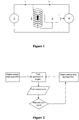
Figure 1 is a schematic representation of a superconducting magnetic assembly employing one embodiment of the invention, -
Figure 2 shows a flow diagram of signal communication between each component of the magnetic assembly, and -
Figure 3 shows a comparison of the magnetic field drift produced by an uncorrected system and a corrected system which incorporates the present invention to stabilise the magnetic field produced. - The invention relates to an assembly for generating a stable superconducting magnetic field.
- Referring to
Figure 1 , the assembly comprises a main magneticpower supply unit 1 across the input terminals of acoil assembly 2. The main magneticpower supply unit 1 aims to provide a main current, typically in the range of 50-1000 Amps to themagnet coil 2. The stability of this main current is typically in a range of a few PPM per hour (parts per million). It is to be understood thatmagnet coil 2 is subject to a number of factors which would cause the magnetic field generated to drift irrespective of the stability of the main input current. Some of these factors include flux redistribution within the superconductor and thermal drift due to small changes in the dimensions of the magnet created by environmental temperature changes. As a result, the magnetic field stability can be no better than the stability of the output current from the mainpower supply unit 1. In long term operations, these magnetic field drifts may grow to a significant amount which could potentially cause serious problems. An example of such magnetic field drift is shown inFigure 3 .Curve 6 indicates the drift value continues to grow with time after 100 minutes and eventually can be higher than 30 PPM after 500 minutes. - In accordance with the invention,
Figure 1 also shows afield measurement device 3 and an auxiliarypower supply unit 4. The field measurement device provides a measurement of the magnetic field present in themagnet 2 and generates an error signal proportional to the drift of the magnetic field away from some predetermined value. This error signal is then fed into the auxiliarypower supply unit 4. Preferably the auxiliarypower supply unit 4 is a low current, low voltage power supply unit which is connected in parallel with the main magneticpower supply unit 1. Upon receiving the error signal which represents the value of the drift, the auxiliarypower supply unit 4 provides a correction current to themagnet coil 2 to correct for such a drift. This is shown inFigure 2 . - In one preferred embodiment the error signal generated by the field measurement device is conditioned by a PID function before it is supplied to the auxiliary power supply unit. The PID function parameters may be optimised to the measured drift rate of the magnet to allow for accurate field control with minimal field oscillations which may be added to the magnetic field by changing the error signal input to the auxiliary power supply unit too rapidly.
- In one preferred embodiment the field measurement device comprises an NMR probe and a detection circuit. It may further comprise a magnetically coupled pick up coil which provides an error signal to the auxiliary
power supply unit 4 in response to the rate of the magnetic field drift. It may alternatively comprise a Hall effect sensor, GMR sensor, or SQUID sensor. - The auxiliary power supply unit provides a highly stable, but significantly lower current to the
magnet 2. For example the auxiliary power supply unit may have a maximum output current of +/- about 0.01 to about 1%, or 0.01 to about 0.5%, or 0.01 to about 0.1% of the output current of the main current unit. The output current by the auxiliarypower supply unit 4 is typically in the range of +/- 100 milli amps. Preferably this current is proportional to the error signal generated by thefield measurement device 3 and has stability typically better than 25 or 10 PPM per hour of the maximum output current of the auxiliary power supply unit. - In one preferred embodiment the
magnet coil 2 is fabricated using a high temperature superconductor (HTS). Alternatively it could be fabricated using a low temperature superconductor (LTS). - The accuracy of the field measurement device can be of the order of PPB (parts per billion) when an NMR probe is employed. This is a few orders of magnitude smaller than the accuracy that may be achieved in the output current by feeding the error signal directly into the main power supply unit since the main output current can usually only be specified to be within a few PPM. The total current flowing through the
magnet 2 can then be controlled, on average, to the accuracy of the secondary PSU, so the magnet current can be varied to an accuracy of better than PPB (parts per billion) and potentially to an accuracy of PPT (parts per trillion).Curve 5 inFigure 3 for a thus corrected current illustrates this, relative touncorrected curve 6. - Where in the foregoing description reference has been made to elements or integers having known equivalents, then such equivalents are included as if they were individually set forth. Although the invention has been described by way of example and with reference to particular embodiments, it is to be understood that modifications and/or improvements may be made without departing from the scope of the invention as defined in the accompanying claims.
Claims (13)
- An assembly for generating a stable magnetic field comprising a main power supply unit (1) arranged to provide a main direct current to a superconducting magnetic circuit to generate a magnetic field, a magnetic field measurement device (3) for measuring the generated magnetic field, and an auxiliary power supply unit (4) in parallel with the main power supply unit (1) and arranged to output an auxiliary direct current to the superconducting magnetic circuit based on the measured magnetic field.
- An assembly according to claim 1 wherein the magnetic field measurement device (3) produces an error signal based on the measured magnetic field value and a predetermined magnetic field value.
- An assembly according to claim 2 wherein the error signal is proportional to the difference between the measured magnetic field value and the predetermined magnetic field value.
- An assembly according to any one of claims 1 to 3 wherein the field measurement device (3) comprises a nuclear magnetic resonance probe and a detection circuit.
- An assembly according to any one of claims 1 to 3 wherein the field measurement device (3) comprises a pick up coil which produces an error signal, dependent upon the rate of change of the magnetic field, indicating the difference between the measured magnetic field and a predetermined magnetic field value.
- An assembly according to any one of claims 1 to 3 wherein the field measurement device (3) is a Hall effect sensor, GMR sensor, or SQUID sensor.
- An assembly according to any one of claims 1 to 6 wherein the error signal is conditioned by a PID function before it is input to the auxiliary power supply unit (4).
- An assembly according to any one of claims 1 to 7 wherein the auxiliary power supply unit (4) has a maximum output current of about +/- 0.01 to about 1% of the output current of the main current unit (1).
- An assembly according to any one of claims 1 to 8 wherein the auxiliary power supply unit (4) has a stability of better than 25 PPM (parts per million) per hour of its maximum output current.
- An assembly according to any one of claims 1 to 9 wherein the main current unit (1) has an output in the range about 50 to about 1000 Amps.
- An assembly according to any one of claims 1 to 10 wherein the superconducting magnetic circuit comprises a high temperature superconductor coil.
- A method for generating a stable superconducting magnetic field, comprising:providing a main direct current to a superconducting magnetic circuit to generate a magnetic field,measuring the generated magnetic field,providing an auxiliary direct current in parallel to the superconducting magnetic circuit and based on the measured magnetic field values.
- A method according to claim 12 including either measuring the generated magnetic field and producing an error signal based on the measured magnetic field value and a predetermined magnetic field value, or measuring the generated magnetic field and producing an error signal based on the measured magnetic field value and a predetermined magnetic field value proportional to the difference between the measured magnetic field value and the predetermined magnetic field value.
Applications Claiming Priority (2)
| Application Number | Priority Date | Filing Date | Title |
|---|---|---|---|
| NZ60167612 | 2012-08-07 | ||
| PCT/NZ2013/000137 WO2014025265A1 (en) | 2012-08-07 | 2013-08-07 | Improved magnetic field control |
Publications (3)
| Publication Number | Publication Date |
|---|---|
| EP2883066A1 EP2883066A1 (en) | 2015-06-17 |
| EP2883066A4 EP2883066A4 (en) | 2016-04-27 |
| EP2883066B1 true EP2883066B1 (en) | 2018-04-04 |
Family
ID=50068402
Family Applications (1)
| Application Number | Title | Priority Date | Filing Date |
|---|---|---|---|
| EP13827064.0A Active EP2883066B1 (en) | 2012-08-07 | 2013-08-07 | Improved magnetic field control |
Country Status (4)
| Country | Link |
|---|---|
| US (2) | US20150187478A1 (en) |
| EP (1) | EP2883066B1 (en) |
| JP (1) | JP2015531170A (en) |
| WO (1) | WO2014025265A1 (en) |
Families Citing this family (5)
| Publication number | Priority date | Publication date | Assignee | Title |
|---|---|---|---|---|
| CN105676151B (en) * | 2016-01-18 | 2018-06-22 | 华东师范大学 | A kind of negative feedback magnetic field sensor |
| CN105813367B (en) * | 2016-03-10 | 2018-06-19 | 东莞中子科学中心 | Method and device for obtaining high-precision time-varying magnetic field on alternating-current magnet |
| US10761163B2 (en) | 2016-06-07 | 2020-09-01 | Koninklijke Philips N.V. | Cryogenic field sensing for compensating magnetic field variations in magnetic resonance imaging magnets |
| EP4053860B1 (en) | 2021-03-05 | 2023-06-21 | Bruker Switzerland AG | A method for charging a superconductor bulk magnet by field-cooling, with at least one non-homogeneous magnetic field component of the applied charger magnetic field |
| US20230047878A1 (en) * | 2021-08-13 | 2023-02-16 | The Regents Of The University Of California | Stabilization and tuning of persistent currents using variable inductance |
Family Cites Families (12)
| Publication number | Priority date | Publication date | Assignee | Title |
|---|---|---|---|---|
| GB1052821A (en) * | 1900-01-01 | |||
| GB825137A (en) * | 1955-07-14 | 1959-12-09 | Siemens Ag | Improvements in or relating to an electrical current measuring apparatus |
| JP2522323B2 (en) * | 1987-09-24 | 1996-08-07 | 株式会社島津製作所 | Electromagnetic force generator |
| JP3542130B2 (en) * | 1994-02-28 | 2004-07-14 | コーニンクレッカ フィリップス エレクトロニクス エヌ ヴィ | Magnetic flux measuring device |
| DE4419061C2 (en) * | 1994-05-31 | 1997-04-30 | Siemens Ag | Arrangement for measuring and controlling the basic field of a magnet of a magnetic resonance imaging device |
| US6208497B1 (en) * | 1997-06-26 | 2001-03-27 | Venture Scientifics, Llc | System and method for servo control of nonlinear electromagnetic actuators |
| GB9904454D0 (en) | 1999-02-27 | 1999-04-21 | Magnex Scient Limited | Superconducting electromagnet apparatus |
| JP3889574B2 (en) * | 2001-04-09 | 2007-03-07 | 株式会社神戸製鋼所 | Superconducting magnet device |
| JP4263544B2 (en) * | 2003-06-23 | 2009-05-13 | 株式会社日立ハイテクノロジーズ | Magnetic field measuring device |
| EP1637898A1 (en) * | 2004-09-16 | 2006-03-22 | Liaisons Electroniques-Mecaniques Lem S.A. | Continuously calibrated magnetic field sensor |
| JP2008020266A (en) * | 2006-07-11 | 2008-01-31 | National Institute For Materials Science | Superconducting magnet device |
| US8203337B2 (en) * | 2009-06-15 | 2012-06-19 | Headway Technologies, Inc. | Elimination of errors due to aging in magneto-resistive devices |
-
2013
- 2013-08-07 EP EP13827064.0A patent/EP2883066B1/en active Active
- 2013-08-07 US US14/419,778 patent/US20150187478A1/en not_active Abandoned
- 2013-08-07 WO PCT/NZ2013/000137 patent/WO2014025265A1/en not_active Ceased
- 2013-08-07 JP JP2015526494A patent/JP2015531170A/en active Pending
-
2016
- 2016-08-22 US US15/242,668 patent/US9666343B2/en active Active
Non-Patent Citations (1)
| Title |
|---|
| None * |
Also Published As
| Publication number | Publication date |
|---|---|
| EP2883066A1 (en) | 2015-06-17 |
| US20160358702A1 (en) | 2016-12-08 |
| EP2883066A4 (en) | 2016-04-27 |
| WO2014025265A1 (en) | 2014-02-13 |
| US20150187478A1 (en) | 2015-07-02 |
| US9666343B2 (en) | 2017-05-30 |
| JP2015531170A (en) | 2015-10-29 |
Similar Documents
| Publication | Publication Date | Title |
|---|---|---|
| US9666343B2 (en) | Magnetic field control | |
| US9354284B2 (en) | Magnetic field sensor configured to measure a magnetic field in a closed loop manner | |
| EP2587269B1 (en) | High current range magnetoresistive current sensor | |
| CA2733431C (en) | Multi-axis fluxgate magnetic sensor | |
| US20200256934A1 (en) | Magnetic sensor system | |
| CN107346007B (en) | Current sensor testing device and testing method | |
| CN107356800A (en) | The high-current detector and method of a kind of magnetic field cancellation | |
| CN104237818B (en) | Gradient system and gradient magnetic field control method, nuclear magnetic resonance imaging system | |
| WO2011105209A1 (en) | Current sensor | |
| WO2011136057A1 (en) | Current sensor | |
| CN106443125A (en) | Dual-wire magnetic field cancellation-based zero-flux high-current detection method | |
| US4823081A (en) | Interference magnetic field compensation method which includes supplying a current to a coil to compensate the field | |
| US20100315928A1 (en) | Elimination of errors due to aging in magneto-resistive devices | |
| CN115053144A (en) | Method and system for improved current sensor | |
| CN110320951A (en) | A kind of current source based on Zero flux current closed-loop feedback | |
| CN112666509B (en) | A compensation system and method suitable for magnetic sensitive current sensor | |
| CN101453868B (en) | External disturbance control system and control method of magnetic environment simulation test equipment | |
| US10018656B2 (en) | Device, arrangement, and method for measuring a current intensity in a primary conductor through which current flows | |
| US20180321330A1 (en) | Magnetic field compensation device | |
| CN105606877B (en) | A kind of closed loop TMR current sensor | |
| JP2008020266A (en) | Superconducting magnet device | |
| EP2388608B1 (en) | Fluxgate sensor circuit for measuring the gradient of a magnetic field | |
| El Bacha et al. | Hysteresis Mitigation in Current Sensor ICs Using Ferromagnetic Cores | |
| KR100841054B1 (en) | Current stabilization device using magnetic field | |
| Zhou et al. | An improved method for compensation of magnetic disturbance created by ferromagnet in measuring position |
Legal Events
| Date | Code | Title | Description |
|---|---|---|---|
| PUAI | Public reference made under article 153(3) epc to a published international application that has entered the european phase |
Free format text: ORIGINAL CODE: 0009012 |
|
| 17P | Request for examination filed |
Effective date: 20150204 |
|
| AK | Designated contracting states |
Kind code of ref document: A1 Designated state(s): AL AT BE BG CH CY CZ DE DK EE ES FI FR GB GR HR HU IE IS IT LI LT LU LV MC MK MT NL NO PL PT RO RS SE SI SK SM TR |
|
| AX | Request for extension of the european patent |
Extension state: BA ME |
|
| DAX | Request for extension of the european patent (deleted) | ||
| RA4 | Supplementary search report drawn up and despatched (corrected) |
Effective date: 20160324 |
|
| RIC1 | Information provided on ipc code assigned before grant |
Ipc: G01R 29/08 20060101AFI20160318BHEP Ipc: G01R 33/02 20060101ALI20160318BHEP |
|
| R17P | Request for examination filed (corrected) |
Effective date: 20150204 |
|
| R17P | Request for examination filed (corrected) |
Effective date: 20150204 |
|
| REG | Reference to a national code |
Ref country code: DE Ref legal event code: R079 Ref document number: 602013035505 Country of ref document: DE Free format text: PREVIOUS MAIN CLASS: G01R0029080000 Ipc: H01F0006000000 |
|
| GRAP | Despatch of communication of intention to grant a patent |
Free format text: ORIGINAL CODE: EPIDOSNIGR1 |
|
| RIC1 | Information provided on ipc code assigned before grant |
Ipc: H01F 6/00 20060101AFI20170327BHEP Ipc: G01R 33/035 20060101ALI20170327BHEP Ipc: G01R 33/24 20060101ALI20170327BHEP Ipc: H01F 6/06 20060101ALI20170327BHEP Ipc: G01R 33/07 20060101ALI20170327BHEP Ipc: G01R 33/00 20060101ALI20170327BHEP Ipc: G01R 33/09 20060101ALI20170327BHEP |
|
| INTG | Intention to grant announced |
Effective date: 20170411 |
|
| GRAJ | Information related to disapproval of communication of intention to grant by the applicant or resumption of examination proceedings by the epo deleted |
Free format text: ORIGINAL CODE: EPIDOSDIGR1 |
|
| INTC | Intention to grant announced (deleted) | ||
| RAP1 | Party data changed (applicant data changed or rights of an application transferred) |
Owner name: SCOTT TECHNOLOGY NZ LIMITED |
|
| GRAP | Despatch of communication of intention to grant a patent |
Free format text: ORIGINAL CODE: EPIDOSNIGR1 |
|
| INTG | Intention to grant announced |
Effective date: 20171020 |
|
| GRAS | Grant fee paid |
Free format text: ORIGINAL CODE: EPIDOSNIGR3 |
|
| GRAA | (expected) grant |
Free format text: ORIGINAL CODE: 0009210 |
|
| AK | Designated contracting states |
Kind code of ref document: B1 Designated state(s): AL AT BE BG CH CY CZ DE DK EE ES FI FR GB GR HR HU IE IS IT LI LT LU LV MC MK MT NL NO PL PT RO RS SE SI SK SM TR |
|
| REG | Reference to a national code |
Ref country code: GB Ref legal event code: FG4D |
|
| REG | Reference to a national code |
Ref country code: CH Ref legal event code: EP |
|
| REG | Reference to a national code |
Ref country code: AT Ref legal event code: REF Ref document number: 986430 Country of ref document: AT Kind code of ref document: T Effective date: 20180415 |
|
| REG | Reference to a national code |
Ref country code: IE Ref legal event code: FG4D |
|
| REG | Reference to a national code |
Ref country code: DE Ref legal event code: R096 Ref document number: 602013035505 Country of ref document: DE |
|
| REG | Reference to a national code |
Ref country code: CH Ref legal event code: NV Representative=s name: BOVARD AG PATENT- UND MARKENANWAELTE, CH |
|
| REG | Reference to a national code |
Ref country code: NL Ref legal event code: MP Effective date: 20180404 |
|
| REG | Reference to a national code |
Ref country code: FR Ref legal event code: PLFP Year of fee payment: 6 |
|
| REG | Reference to a national code |
Ref country code: LT Ref legal event code: MG4D |
|
| PG25 | Lapsed in a contracting state [announced via postgrant information from national office to epo] |
Ref country code: NL Free format text: LAPSE BECAUSE OF FAILURE TO SUBMIT A TRANSLATION OF THE DESCRIPTION OR TO PAY THE FEE WITHIN THE PRESCRIBED TIME-LIMIT Effective date: 20180404 |
|
| PG25 | Lapsed in a contracting state [announced via postgrant information from national office to epo] |
Ref country code: AL Free format text: LAPSE BECAUSE OF FAILURE TO SUBMIT A TRANSLATION OF THE DESCRIPTION OR TO PAY THE FEE WITHIN THE PRESCRIBED TIME-LIMIT Effective date: 20180404 Ref country code: FI Free format text: LAPSE BECAUSE OF FAILURE TO SUBMIT A TRANSLATION OF THE DESCRIPTION OR TO PAY THE FEE WITHIN THE PRESCRIBED TIME-LIMIT Effective date: 20180404 Ref country code: BG Free format text: LAPSE BECAUSE OF FAILURE TO SUBMIT A TRANSLATION OF THE DESCRIPTION OR TO PAY THE FEE WITHIN THE PRESCRIBED TIME-LIMIT Effective date: 20180704 Ref country code: LT Free format text: LAPSE BECAUSE OF FAILURE TO SUBMIT A TRANSLATION OF THE DESCRIPTION OR TO PAY THE FEE WITHIN THE PRESCRIBED TIME-LIMIT Effective date: 20180404 Ref country code: PL Free format text: LAPSE BECAUSE OF FAILURE TO SUBMIT A TRANSLATION OF THE DESCRIPTION OR TO PAY THE FEE WITHIN THE PRESCRIBED TIME-LIMIT Effective date: 20180404 Ref country code: SE Free format text: LAPSE BECAUSE OF FAILURE TO SUBMIT A TRANSLATION OF THE DESCRIPTION OR TO PAY THE FEE WITHIN THE PRESCRIBED TIME-LIMIT Effective date: 20180404 Ref country code: NO Free format text: LAPSE BECAUSE OF FAILURE TO SUBMIT A TRANSLATION OF THE DESCRIPTION OR TO PAY THE FEE WITHIN THE PRESCRIBED TIME-LIMIT Effective date: 20180704 Ref country code: ES Free format text: LAPSE BECAUSE OF FAILURE TO SUBMIT A TRANSLATION OF THE DESCRIPTION OR TO PAY THE FEE WITHIN THE PRESCRIBED TIME-LIMIT Effective date: 20180404 |
|
| PG25 | Lapsed in a contracting state [announced via postgrant information from national office to epo] |
Ref country code: RS Free format text: LAPSE BECAUSE OF FAILURE TO SUBMIT A TRANSLATION OF THE DESCRIPTION OR TO PAY THE FEE WITHIN THE PRESCRIBED TIME-LIMIT Effective date: 20180404 Ref country code: HR Free format text: LAPSE BECAUSE OF FAILURE TO SUBMIT A TRANSLATION OF THE DESCRIPTION OR TO PAY THE FEE WITHIN THE PRESCRIBED TIME-LIMIT Effective date: 20180404 Ref country code: LV Free format text: LAPSE BECAUSE OF FAILURE TO SUBMIT A TRANSLATION OF THE DESCRIPTION OR TO PAY THE FEE WITHIN THE PRESCRIBED TIME-LIMIT Effective date: 20180404 Ref country code: GR Free format text: LAPSE BECAUSE OF FAILURE TO SUBMIT A TRANSLATION OF THE DESCRIPTION OR TO PAY THE FEE WITHIN THE PRESCRIBED TIME-LIMIT Effective date: 20180705 |
|
| REG | Reference to a national code |
Ref country code: AT Ref legal event code: MK05 Ref document number: 986430 Country of ref document: AT Kind code of ref document: T Effective date: 20180404 |
|
| PG25 | Lapsed in a contracting state [announced via postgrant information from national office to epo] |
Ref country code: PT Free format text: LAPSE BECAUSE OF FAILURE TO SUBMIT A TRANSLATION OF THE DESCRIPTION OR TO PAY THE FEE WITHIN THE PRESCRIBED TIME-LIMIT Effective date: 20180806 |
|
| REG | Reference to a national code |
Ref country code: DE Ref legal event code: R097 Ref document number: 602013035505 Country of ref document: DE |
|
| PG25 | Lapsed in a contracting state [announced via postgrant information from national office to epo] |
Ref country code: SK Free format text: LAPSE BECAUSE OF FAILURE TO SUBMIT A TRANSLATION OF THE DESCRIPTION OR TO PAY THE FEE WITHIN THE PRESCRIBED TIME-LIMIT Effective date: 20180404 Ref country code: EE Free format text: LAPSE BECAUSE OF FAILURE TO SUBMIT A TRANSLATION OF THE DESCRIPTION OR TO PAY THE FEE WITHIN THE PRESCRIBED TIME-LIMIT Effective date: 20180404 Ref country code: CZ Free format text: LAPSE BECAUSE OF FAILURE TO SUBMIT A TRANSLATION OF THE DESCRIPTION OR TO PAY THE FEE WITHIN THE PRESCRIBED TIME-LIMIT Effective date: 20180404 Ref country code: RO Free format text: LAPSE BECAUSE OF FAILURE TO SUBMIT A TRANSLATION OF THE DESCRIPTION OR TO PAY THE FEE WITHIN THE PRESCRIBED TIME-LIMIT Effective date: 20180404 Ref country code: DK Free format text: LAPSE BECAUSE OF FAILURE TO SUBMIT A TRANSLATION OF THE DESCRIPTION OR TO PAY THE FEE WITHIN THE PRESCRIBED TIME-LIMIT Effective date: 20180404 Ref country code: AT Free format text: LAPSE BECAUSE OF FAILURE TO SUBMIT A TRANSLATION OF THE DESCRIPTION OR TO PAY THE FEE WITHIN THE PRESCRIBED TIME-LIMIT Effective date: 20180404 |
|
| PLBE | No opposition filed within time limit |
Free format text: ORIGINAL CODE: 0009261 |
|
| STAA | Information on the status of an ep patent application or granted ep patent |
Free format text: STATUS: NO OPPOSITION FILED WITHIN TIME LIMIT |
|
| PG25 | Lapsed in a contracting state [announced via postgrant information from national office to epo] |
Ref country code: SM Free format text: LAPSE BECAUSE OF FAILURE TO SUBMIT A TRANSLATION OF THE DESCRIPTION OR TO PAY THE FEE WITHIN THE PRESCRIBED TIME-LIMIT Effective date: 20180404 |
|
| 26N | No opposition filed |
Effective date: 20190107 |
|
| PG25 | Lapsed in a contracting state [announced via postgrant information from national office to epo] |
Ref country code: MC Free format text: LAPSE BECAUSE OF FAILURE TO SUBMIT A TRANSLATION OF THE DESCRIPTION OR TO PAY THE FEE WITHIN THE PRESCRIBED TIME-LIMIT Effective date: 20180404 |
|
| PG25 | Lapsed in a contracting state [announced via postgrant information from national office to epo] |
Ref country code: LU Free format text: LAPSE BECAUSE OF NON-PAYMENT OF DUE FEES Effective date: 20180807 |
|
| REG | Reference to a national code |
Ref country code: BE Ref legal event code: MM Effective date: 20180831 |
|
| REG | Reference to a national code |
Ref country code: IE Ref legal event code: MM4A |
|
| PG25 | Lapsed in a contracting state [announced via postgrant information from national office to epo] |
Ref country code: SI Free format text: LAPSE BECAUSE OF FAILURE TO SUBMIT A TRANSLATION OF THE DESCRIPTION OR TO PAY THE FEE WITHIN THE PRESCRIBED TIME-LIMIT Effective date: 20180404 |
|
| PG25 | Lapsed in a contracting state [announced via postgrant information from national office to epo] |
Ref country code: IE Free format text: LAPSE BECAUSE OF NON-PAYMENT OF DUE FEES Effective date: 20180807 |
|
| PG25 | Lapsed in a contracting state [announced via postgrant information from national office to epo] |
Ref country code: BE Free format text: LAPSE BECAUSE OF NON-PAYMENT OF DUE FEES Effective date: 20180831 |
|
| PG25 | Lapsed in a contracting state [announced via postgrant information from national office to epo] |
Ref country code: MT Free format text: LAPSE BECAUSE OF NON-PAYMENT OF DUE FEES Effective date: 20180807 |
|
| PG25 | Lapsed in a contracting state [announced via postgrant information from national office to epo] |
Ref country code: TR Free format text: LAPSE BECAUSE OF FAILURE TO SUBMIT A TRANSLATION OF THE DESCRIPTION OR TO PAY THE FEE WITHIN THE PRESCRIBED TIME-LIMIT Effective date: 20180404 |
|
| PG25 | Lapsed in a contracting state [announced via postgrant information from national office to epo] |
Ref country code: HU Free format text: LAPSE BECAUSE OF FAILURE TO SUBMIT A TRANSLATION OF THE DESCRIPTION OR TO PAY THE FEE WITHIN THE PRESCRIBED TIME-LIMIT; INVALID AB INITIO Effective date: 20130807 |
|
| PG25 | Lapsed in a contracting state [announced via postgrant information from national office to epo] |
Ref country code: MK Free format text: LAPSE BECAUSE OF NON-PAYMENT OF DUE FEES Effective date: 20180404 Ref country code: CY Free format text: LAPSE BECAUSE OF FAILURE TO SUBMIT A TRANSLATION OF THE DESCRIPTION OR TO PAY THE FEE WITHIN THE PRESCRIBED TIME-LIMIT Effective date: 20180404 |
|
| PG25 | Lapsed in a contracting state [announced via postgrant information from national office to epo] |
Ref country code: IS Free format text: LAPSE BECAUSE OF FAILURE TO SUBMIT A TRANSLATION OF THE DESCRIPTION OR TO PAY THE FEE WITHIN THE PRESCRIBED TIME-LIMIT Effective date: 20180804 |
|
| REG | Reference to a national code |
Ref country code: DE Ref legal event code: R081 Ref document number: 602013035505 Country of ref document: DE Owner name: HTS-110 LIMITED PARTNERSHIP, WAIWHETU, NZ Free format text: FORMER OWNER: SCOTT TECHNOLOGY NZ LTD., DUNEDIN, NZ |
|
| REG | Reference to a national code |
Ref country code: GB Ref legal event code: 732E Free format text: REGISTERED BETWEEN 20220224 AND 20220302 |
|
| PGFP | Annual fee paid to national office [announced via postgrant information from national office to epo] |
Ref country code: DE Payment date: 20250828 Year of fee payment: 13 |
|
| PGFP | Annual fee paid to national office [announced via postgrant information from national office to epo] |
Ref country code: IT Payment date: 20250725 Year of fee payment: 13 |
|
| PGFP | Annual fee paid to national office [announced via postgrant information from national office to epo] |
Ref country code: GB Payment date: 20250805 Year of fee payment: 13 |
|
| PGFP | Annual fee paid to national office [announced via postgrant information from national office to epo] |
Ref country code: FR Payment date: 20250730 Year of fee payment: 13 |
|
| PGFP | Annual fee paid to national office [announced via postgrant information from national office to epo] |
Ref country code: CH Payment date: 20250901 Year of fee payment: 13 |