EP2882570B1 - Post processing of components that are laser peened - Google Patents
Post processing of components that are laser peened Download PDFInfo
- Publication number
- EP2882570B1 EP2882570B1 EP13848323.5A EP13848323A EP2882570B1 EP 2882570 B1 EP2882570 B1 EP 2882570B1 EP 13848323 A EP13848323 A EP 13848323A EP 2882570 B1 EP2882570 B1 EP 2882570B1
- Authority
- EP
- European Patent Office
- Prior art keywords
- laser
- component
- layer
- airfoil
- turbine
- Prior art date
- Legal status (The legal status is an assumption and is not a legal conclusion. Google has not performed a legal analysis and makes no representation as to the accuracy of the status listed.)
- Active
Links
Images



Classifications
-
- C—CHEMISTRY; METALLURGY
- C21—METALLURGY OF IRON
- C21D—MODIFYING THE PHYSICAL STRUCTURE OF FERROUS METALS; GENERAL DEVICES FOR HEAT TREATMENT OF FERROUS OR NON-FERROUS METALS OR ALLOYS; MAKING METAL MALLEABLE, e.g. BY DECARBURISATION OR TEMPERING
- C21D10/00—Modifying the physical properties by methods other than heat treatment or deformation
- C21D10/005—Modifying the physical properties by methods other than heat treatment or deformation by laser shock processing
-
- B—PERFORMING OPERATIONS; TRANSPORTING
- B23—MACHINE TOOLS; METAL-WORKING NOT OTHERWISE PROVIDED FOR
- B23K—SOLDERING OR UNSOLDERING; WELDING; CLADDING OR PLATING BY SOLDERING OR WELDING; CUTTING BY APPLYING HEAT LOCALLY, e.g. FLAME CUTTING; WORKING BY LASER BEAM
- B23K26/00—Working by laser beam, e.g. welding, cutting or boring
- B23K26/352—Working by laser beam, e.g. welding, cutting or boring for surface treatment
- B23K26/356—Working by laser beam, e.g. welding, cutting or boring for surface treatment by shock processing
-
- B—PERFORMING OPERATIONS; TRANSPORTING
- B24—GRINDING; POLISHING
- B24B—MACHINES, DEVICES, OR PROCESSES FOR GRINDING OR POLISHING; DRESSING OR CONDITIONING OF ABRADING SURFACES; FEEDING OF GRINDING, POLISHING, OR LAPPING AGENTS
- B24B19/00—Single-purpose machines or devices for particular grinding operations not covered by any other main group
- B24B19/14—Single-purpose machines or devices for particular grinding operations not covered by any other main group for grinding turbine blades, propeller blades or the like
-
- B—PERFORMING OPERATIONS; TRANSPORTING
- B24—GRINDING; POLISHING
- B24C—ABRASIVE OR RELATED BLASTING WITH PARTICULATE MATERIAL
- B24C1/00—Methods for use of abrasive blasting for producing particular effects; Use of auxiliary equipment in connection with such methods
-
- F—MECHANICAL ENGINEERING; LIGHTING; HEATING; WEAPONS; BLASTING
- F01—MACHINES OR ENGINES IN GENERAL; ENGINE PLANTS IN GENERAL; STEAM ENGINES
- F01D—NON-POSITIVE DISPLACEMENT MACHINES OR ENGINES, e.g. STEAM TURBINES
- F01D5/00—Blades; Blade-carrying members; Heating, heat-insulating, cooling or antivibration means on the blades or the members
- F01D5/12—Blades
- F01D5/28—Selecting particular materials; Particular measures relating thereto; Measures against erosion or corrosion
- F01D5/286—Particular treatment of blades, e.g. to increase durability or resistance against corrosion or erosion
-
- B—PERFORMING OPERATIONS; TRANSPORTING
- B23—MACHINE TOOLS; METAL-WORKING NOT OTHERWISE PROVIDED FOR
- B23P—METAL-WORKING NOT OTHERWISE PROVIDED FOR; COMBINED OPERATIONS; UNIVERSAL MACHINE TOOLS
- B23P15/00—Making specific metal objects by operations not covered by a single other subclass or a group in this subclass
- B23P15/02—Making specific metal objects by operations not covered by a single other subclass or a group in this subclass turbine or like blades from one piece
-
- B—PERFORMING OPERATIONS; TRANSPORTING
- B23—MACHINE TOOLS; METAL-WORKING NOT OTHERWISE PROVIDED FOR
- B23P—METAL-WORKING NOT OTHERWISE PROVIDED FOR; COMBINED OPERATIONS; UNIVERSAL MACHINE TOOLS
- B23P9/00—Treating or finishing surfaces mechanically, with or without calibrating, primarily to resist wear or impact, e.g. smoothing or roughening turbine blades or bearings; Features of such surfaces not otherwise provided for, their treatment being unspecified
-
- Y—GENERAL TAGGING OF NEW TECHNOLOGICAL DEVELOPMENTS; GENERAL TAGGING OF CROSS-SECTIONAL TECHNOLOGIES SPANNING OVER SEVERAL SECTIONS OF THE IPC; TECHNICAL SUBJECTS COVERED BY FORMER USPC CROSS-REFERENCE ART COLLECTIONS [XRACs] AND DIGESTS
- Y10—TECHNICAL SUBJECTS COVERED BY FORMER USPC
- Y10T—TECHNICAL SUBJECTS COVERED BY FORMER US CLASSIFICATION
- Y10T29/00—Metal working
- Y10T29/49—Method of mechanical manufacture
- Y10T29/49316—Impeller making
- Y10T29/49336—Blade making
Definitions
- This application relates to post processing of laser peened articles.
- Laser peening is a surface treatment that induces deep compressive residual stresses. The compression increases the damage tolerance of a metal material.
- One method of laser peening an article is to prepare the material by covering it with a sacrificial ablative layer. Typically, this ablative layer is an applied medium, such as tape or paint to avoid base metal damage of the component during laser peening.
- a medium typically water, covers the ablative layer and acts to confine the plasma that will develop after the laser strike.
- a laser pulse is directed at the material. When the laser hits the material, an explosion of expanding plasma is formed between the ablative layer and the water layer. This explosion of plasma creates a shock wave that compresses and works the outer layer of the material.
- Another method of laser peening a material is to use the surface of the base metal itself as an ablative medium. A portion of the base material is used to create the plasma that produces the shock wave, subsequently damaging the base material surface. An example of such damage is micro-cracking, as well as detrimental tensile residual stress. This damaged material is known as a remelt layer.
- the depth of the laser re-melt layer removed across steps a) - c) is less than 1 mil (0.0254 mm) per side.
- the laser remelt layer is on a portion of a turbine engine component.
- the component includes an airfoil.
- the component is a blade.
- the component is a vane.
- the component is a shaft.
- the component is a disk.
- Also disclosed herein is a method of manufacturing a gas turbine component having an airfoil includes the steps of: a) laser shock peening a base metal surface of the component; b) then grit blasting the surface; c) then chemically etching the surface after the grit blasting; and then mechanically finishing the surface after the chemical etching.
- the depth of the laser re-melt layer removed may be less than 1 mil (0.0254 mm) per side.
- the component may be a vane.
- the component may be a blade.
- FIG. 1 schematically illustrates a gas turbine engine 20.
- the gas turbine engine 20 is disclosed herein as a two-spool turbofan that generally incorporates a fan section 22, a compressor section 24, a combustor section 26 and a turbine section 28.
- Alternative engines might include an augmentor section (not shown) among other systems or features.
- the fan section 22 drives air along a bypass flowpath B while the compressor section 24 drives air along a core flowpath C for compression and communication into the combustor section 26 then expansion through the turbine section 28.
- FIG. 1 schematically illustrates a gas turbine engine 20.
- the gas turbine engine 20 is disclosed herein as a two-spool turbofan that generally incorporates a fan section 22, a compressor section 24, a combustor section 26 and a turbine section 28.
- Alternative engines might include an augmentor section (not shown) among other systems or features.
- the fan section 22 drives air along a bypass flowpath B while the compressor section 24 drives air along a core flowpath C for compression and communication into the comb
- the engine 20 generally includes a low speed spool 30 and a high speed spool 32 mounted for rotation about an engine central longitudinal axis A relative to an engine static structure 36 via several bearing systems 38. It should be understood that various bearing systems 38 at various locations may alternatively or additionally be provided.
- the core airflow is compressed by the low pressure compressor 44 then the high pressure compressor 52, mixed and burned with fuel in the combustor 56, then expanded over the high pressure turbine 54 and low pressure turbine 46.
- the mid-turbine frame 57 includes airfoils 59 which are in the core airflow path.
- the turbines 46, 54 rotationally drive the respective low speed spool 30 and high speed spool 32 in response to the expansion.
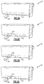
- FIG 2A schematically shows a base metal surface 25 of an engine blade airfoil 21 for use in gas turbine engine 20.
- the airfoil 21 may be a turbine or compressor blade or vane.
- the surface 25 is being laser peened using a laser peening system 100. The laser peening of base metal surface 25 is not sequenced with an ablative medium.
- Figure 2B shows an engine blade airfoil 21 that has been laser peened.
- a laser remelt layer 23 results due to the creation of plasma with a portion of the base metal surface 25 in direct contact with the laser. It should be understood that the remelt layer 23 may extend over a greater surface than is illustrated.
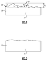
- Figure 4 schematically illustrates a magnified view of the laser remelt layer 23 of the engine blade airfoil 21 post laser peening.
- the laser remelt layer 23 has a damaged area 47. This damaged area 47 may be brittle and/or micro-cracked.
- the laser remelt layer 23 will undergo a removal and finishing method at the damaged area 47 to improve the condition of the base metal surface 25.
- the damage area 47 is over a small thickness shown as d 1 .
- d 1 may be less than 1 mil (0.0254 mm).
- a grit blasting tool 102 shown schematically, is used to grit blast the remelt layer 23. This is the first step used to remove the laser remelt layer 23 and prepare the surface 25 for chemical etching.
- the grit blasting tool 102 can target a specific depth of the damaged area 47 on the engine blade airfoil 21 for removal.
- the airfoil 21 is next subjected to a chemical removal process 104, as shown schematically in Figure 2D .
- the chemical removal process 104 etches the base metal surface 25 and removes some or all of the damaged area 47, depending on the process parameters utilized.
- the base metal surface 25 of an airfoil 21 is then finished using a mechanical removal operation 106, as shown schematically in Figure 2E .
- the mechanical removal process may be similar to those in media finishing techniques.
- Medial finishing techniques are known to workers of ordinary skill in this art.
- the finishing process parameters and controls ensure full removal of the remelt layer 23 while also removing any surface attack that might have resulted from the chemical etching process.
- the specific depth of the damaged area 47 removed across steps 2C-2E is less than 1 mil (0.0254 mm) total per side of the base metal surface 25.
- FIG. 5 schematically shows an area similar to that shown in Figure 4 , after processing.
Landscapes
- Engineering & Computer Science (AREA)
- Mechanical Engineering (AREA)
- Chemical & Material Sciences (AREA)
- Physics & Mathematics (AREA)
- Materials Engineering (AREA)
- Optics & Photonics (AREA)
- Thermal Sciences (AREA)
- General Engineering & Computer Science (AREA)
- Crystallography & Structural Chemistry (AREA)
- Metallurgy (AREA)
- Organic Chemistry (AREA)
- Plasma & Fusion (AREA)
- Laser Beam Processing (AREA)
- Turbine Rotor Nozzle Sealing (AREA)
- ing And Chemical Polishing (AREA)
- Structures Of Non-Positive Displacement Pumps (AREA)
- Surface Treatment Of Glass (AREA)
- Other Surface Treatments For Metallic Materials (AREA)
Description
- This application relates to post processing of laser peened articles.
- Laser peening is a surface treatment that induces deep compressive residual stresses. The compression increases the damage tolerance of a metal material. One method of laser peening an article is to prepare the material by covering it with a sacrificial ablative layer. Typically, this ablative layer is an applied medium, such as tape or paint to avoid base metal damage of the component during laser peening.
- A medium, typically water, covers the ablative layer and acts to confine the plasma that will develop after the laser strike. A laser pulse is directed at the material. When the laser hits the material, an explosion of expanding plasma is formed between the ablative layer and the water layer. This explosion of plasma creates a shock wave that compresses and works the outer layer of the material.
- Another method of laser peening a material is to use the surface of the base metal itself as an ablative medium. A portion of the base material is used to create the plasma that produces the shock wave, subsequently damaging the base material surface. An example of such damage is micro-cracking, as well as detrimental tensile residual stress. This damaged material is known as a remelt layer.
- Post processing to remove the remelt layer and finish the component surface has been proposed.
- Known finishing methods are disclosed in
US 2010/249926 andUS 7,776,165 ,US 5,744,781 andUS 2011/0005493 . - In accordance with the invention, there is provided a method of finishing and removing laser remelt layer of a compound as set forth in claim 1.
- In another embodiment according to any of the previous embodiments, the depth of the laser re-melt layer removed across steps a) - c) is less than 1 mil (0.0254 mm) per side.
- In another embodiment according to any of the previous embodiments, the laser remelt layer is on a portion of a turbine engine component.
- In another embodiment according to any of the previous embodiments, the component includes an airfoil.
- In another embodiment according to any of the previous embodiments, the component is a blade.
- In another embodiment according to any of the previous embodiments, the component is a vane.
- In another embodiment according to any of the previous embodiments, the component is a shaft.
- In another embodiment according to any of the previous embodiments, the component is a disk.
- Also disclosed herein is a method of manufacturing a gas turbine component having an airfoil includes the steps of: a) laser shock peening a base metal surface of the component; b) then grit blasting the surface; c) then chemically etching the surface after the grit blasting; and then mechanically finishing the surface after the chemical etching.
- The depth of the laser re-melt layer removed may be less than 1 mil (0.0254 mm) per side.
- The component may be a vane.
- The component may be a blade.
- These and other features of this application will be best understood from the following specification and drawings, the following of which is a brief description.
-
-
Figure 1 illustrates an example gas turbine engine; -
Figure 2A illustrates a perspective view of an embodiment of a turbine airfoil of the engine shown inFigure 1 ; -
Figure 2B illustrates the turbine airfoil being laser peened; -
Figure 2C illustrates the turbine airfoil being grit blasted; -
Figure 2D illustrates the turbine airfoil being chemically etched; -
Figure 2E illustrates the turbine airfoil being mechanically finished; -
Figure 3 is a flowchart for a finishing process; -
Figure 4 illustrates a before view of a turbine airfoil prior to the step illustrated inFigure 2C ; and -
Figure 5 schematically illustrates a view of the turbine airfoil shown inFigure 4 after step 2E. -
Figure 1 schematically illustrates agas turbine engine 20. Thegas turbine engine 20 is disclosed herein as a two-spool turbofan that generally incorporates afan section 22, acompressor section 24, acombustor section 26 and aturbine section 28. Alternative engines might include an augmentor section (not shown) among other systems or features. Thefan section 22 drives air along a bypass flowpath B while thecompressor section 24 drives air along a core flowpath C for compression and communication into thecombustor section 26 then expansion through theturbine section 28. Although depicted as a turbofan gas turbine engine in the disclosed non-limiting embodiment, it should be understood that the concepts described herein are not limited to use with turbofans as the teachings may be applied to other types of turbine engines including three-spool architectures. - The
engine 20 generally includes alow speed spool 30 and ahigh speed spool 32 mounted for rotation about an engine central longitudinal axis A relative to an engine static structure 36 viaseveral bearing systems 38. It should be understood thatvarious bearing systems 38 at various locations may alternatively or additionally be provided. - The core airflow is compressed by the
low pressure compressor 44 then thehigh pressure compressor 52, mixed and burned with fuel in thecombustor 56, then expanded over thehigh pressure turbine 54 andlow pressure turbine 46. Themid-turbine frame 57 includesairfoils 59 which are in the core airflow path. Theturbines low speed spool 30 andhigh speed spool 32 in response to the expansion. -
Figure 2A schematically shows abase metal surface 25 of anengine blade airfoil 21 for use ingas turbine engine 20. Theairfoil 21 may be a turbine or compressor blade or vane. Thesurface 25 is being laser peened using alaser peening system 100. The laser peening ofbase metal surface 25 is not sequenced with an ablative medium. -
Figure 2B shows anengine blade airfoil 21 that has been laser peened. Alaser remelt layer 23 results due to the creation of plasma with a portion of thebase metal surface 25 in direct contact with the laser. It should be understood that theremelt layer 23 may extend over a greater surface than is illustrated. -
Figure 4 schematically illustrates a magnified view of thelaser remelt layer 23 of theengine blade airfoil 21 post laser peening. Thelaser remelt layer 23 has a damagedarea 47. This damagedarea 47 may be brittle and/or micro-cracked. - As will be described below, the
laser remelt layer 23 will undergo a removal and finishing method at the damagedarea 47 to improve the condition of thebase metal surface 25. As illustrated, thedamage area 47 is over a small thickness shown as d1. In practice, d1 may be less than 1 mil (0.0254 mm). - Referring to
Figure 2C , agrit blasting tool 102, shown schematically, is used to grit blast theremelt layer 23. This is the first step used to remove thelaser remelt layer 23 and prepare thesurface 25 for chemical etching. By usage of known process controls, thegrit blasting tool 102 can target a specific depth of the damagedarea 47 on theengine blade airfoil 21 for removal. - The
airfoil 21 is next subjected to achemical removal process 104, as shown schematically inFigure 2D . Thechemical removal process 104 etches thebase metal surface 25 and removes some or all of the damagedarea 47, depending on the process parameters utilized. - The
base metal surface 25 of anairfoil 21 is then finished using amechanical removal operation 106, as shown schematically inFigure 2E . The mechanical removal process may be similar to those in media finishing techniques. Medial finishing techniques are known to workers of ordinary skill in this art. The finishing process parameters and controls ensure full removal of theremelt layer 23 while also removing any surface attack that might have resulted from the chemical etching process. - In one example, the specific depth of the damaged
area 47 removed across steps 2C-2E is less than 1 mil (0.0254 mm) total per side of thebase metal surface 25. - Post processing of the above described of the
base metal surface 25 removes the damagedarea 47.Figure 5 schematically shows an area similar to that shown inFigure 4 , after processing. - While this disclosure is specifically directed to airfoils, other components such as vanes, disks, shafts, etc... may benefit from this invention.
- Although an embodiment of this invention has been disclosed, a worker of ordinary skill in this art would recognize that certain modifications would come within the scope of this invention. For that reason, the following claims should be studied to determine the true scope and content of this invention. In addition, this invention is not limited to application to gas turbine airfoils, though this article was used for illustration purposes.
Claims (8)
- A method of finishing and removing a laser remelt layer (23) of a component (21) generated by a laser peening process, comprising:a) grit blasting (2) a surface (25) at a remelt layer (23);b) then chemically etching (3) the surface (25); andc) then mechanically finishing (4) the surface (25).
- The method of claim 1, wherein the depth of the laser (23) re-melt layer removed across steps a) - c) is less than 0.0254 mm per side.
- The method of any preceding claim, wherein the laser re-melt layer (23) is on a portion of a turbine engine component (21).
- The method of claim 3, wherein the component (21) includes an airfoil.
- The method of claim 4, wherein the component (21) is a blade.
- The method of claim 4, wherein the component (21) is a vane.
- The method of claim 3, wherein the component (21) is a shaft.
- The method of claim 3, wherein the component (21) is a disk.
Applications Claiming Priority (2)
| Application Number | Priority Date | Filing Date | Title |
|---|---|---|---|
| US13/584,257 US9803258B2 (en) | 2012-08-13 | 2012-08-13 | Post processing of components that are laser peened |
| PCT/US2013/053685 WO2014065921A2 (en) | 2012-08-13 | 2013-08-06 | Post processing of components that are laser peened |
Publications (3)
| Publication Number | Publication Date |
|---|---|
| EP2882570A2 EP2882570A2 (en) | 2015-06-17 |
| EP2882570A4 EP2882570A4 (en) | 2015-08-26 |
| EP2882570B1 true EP2882570B1 (en) | 2016-11-02 |
Family
ID=50065068
Family Applications (1)
| Application Number | Title | Priority Date | Filing Date |
|---|---|---|---|
| EP13848323.5A Active EP2882570B1 (en) | 2012-08-13 | 2013-08-06 | Post processing of components that are laser peened |
Country Status (5)
| Country | Link |
|---|---|
| US (1) | US9803258B2 (en) |
| EP (1) | EP2882570B1 (en) |
| JP (1) | JP2015533973A (en) |
| CN (1) | CN104582900A (en) |
| WO (1) | WO2014065921A2 (en) |
Families Citing this family (5)
| Publication number | Priority date | Publication date | Assignee | Title |
|---|---|---|---|---|
| CN103203543B (en) * | 2013-02-04 | 2015-03-11 | 中国航空工业集团公司北京航空制造工程研究所 | Method and device for injecting water restraint layer of laser shock processing blade |
| CN107253148B (en) * | 2017-04-25 | 2020-05-01 | 江苏大学 | Combination method for forming gradient nano structure on surface layer of metal workpiece |
| JP6569745B2 (en) | 2018-01-29 | 2019-09-04 | Jfeスチール株式会社 | Hot rolled steel sheet for coiled tubing and method for producing the same |
| CN108941805B (en) * | 2018-08-09 | 2020-02-21 | 广东工业大学 | A method for preparing surface microstructures by electrochemical polarization of stainless steel |
| JP7409245B2 (en) * | 2020-07-13 | 2024-01-09 | 新東工業株式会社 | Surface treatment method |
Family Cites Families (18)
| Publication number | Priority date | Publication date | Assignee | Title |
|---|---|---|---|---|
| US4454740A (en) | 1981-09-10 | 1984-06-19 | United Technologies Corporation | Method for simultaneous peening and smoothing |
| US4732312A (en) | 1986-11-10 | 1988-03-22 | Grumman Aerospace Corporation | Method for diffusion bonding of alloys having low solubility oxides |
| US5415336A (en) * | 1992-11-19 | 1995-05-16 | Alliedsignal Inc. | Method for preparing a composite surface for diffusion bonding |
| US5591009A (en) | 1995-01-17 | 1997-01-07 | General Electric Company | Laser shock peened gas turbine engine fan blade edges |
| US5744781A (en) | 1995-08-07 | 1998-04-28 | General Electric Company | Method and apparatus for laser shock peening |
| KR100266881B1 (en) | 1997-07-29 | 2000-10-02 | 이종훈 | Process for surface-alloying on plated metal or alloy substkates, or for the surface-repairing of damaged(or failed) metal or alloy substrates by using a laser beam |
| US6238187B1 (en) | 1999-10-14 | 2001-05-29 | Lsp Technologies, Inc. | Method using laser shock peening to process airfoil weld repairs pertaining to blade cut and weld techniques |
| US6339878B1 (en) | 2000-03-27 | 2002-01-22 | United Technologies Corporation | Method of repairing an airfoil |
| US6852179B1 (en) | 2000-06-09 | 2005-02-08 | Lsp Technologies Inc. | Method of modifying a workpiece following laser shock processing |
| TWI258532B (en) | 2003-06-10 | 2006-07-21 | Ishikawajima Harima Heavy Ind | Turbine component, gas turbine engine, method for manufacturing turbine component, surface processing method, vane component, metal component, and steam turbine engine |
| US20060009857A1 (en) | 2004-07-08 | 2006-01-12 | Gibbs Phillip M | Method and apparatus for surface hardening implants |
| US7540997B2 (en) * | 2005-08-23 | 2009-06-02 | Boston Scientific Scimed, Inc. | Medical devices having alloy compositions |
| US20100136296A1 (en) | 2006-11-30 | 2010-06-03 | United Technologies Corporation | Densification of coating using laser peening |
| US8471168B2 (en) | 2008-06-19 | 2013-06-25 | General Electric Company | Methods of treating metal articles and articles made therefrom |
| CN101457322B (en) | 2009-01-07 | 2010-08-18 | 济南大学 | TiAl base pressure booster turbo and method for producing the same |
| HUE039884T2 (en) | 2009-03-12 | 2019-02-28 | Nippon Steel & Sumitomo Metal Corp | Method of producing common rail and common rail |
| US20100249926A1 (en) | 2009-03-24 | 2010-09-30 | X-Spine Systems, Inc. | Implant and a system and method for processing, desiging and manufacturing an improved orthopedic implant |
| CN102335789A (en) | 2011-11-11 | 2012-02-01 | 沈阳黎明航空发动机(集团)有限责任公司 | Device and method for removing re-melting layers on inner walls of air film holes of blades |
-
2012
- 2012-08-13 US US13/584,257 patent/US9803258B2/en active Active
-
2013
- 2013-08-06 CN CN201380043228.2A patent/CN104582900A/en active Pending
- 2013-08-06 JP JP2015527482A patent/JP2015533973A/en active Pending
- 2013-08-06 EP EP13848323.5A patent/EP2882570B1/en active Active
- 2013-08-06 WO PCT/US2013/053685 patent/WO2014065921A2/en not_active Ceased
Also Published As
| Publication number | Publication date |
|---|---|
| CN104582900A (en) | 2015-04-29 |
| WO2014065921A3 (en) | 2014-06-19 |
| JP2015533973A (en) | 2015-11-26 |
| EP2882570A4 (en) | 2015-08-26 |
| WO2014065921A2 (en) | 2014-05-01 |
| US20140041224A1 (en) | 2014-02-13 |
| US9803258B2 (en) | 2017-10-31 |
| EP2882570A2 (en) | 2015-06-17 |
Similar Documents
| Publication | Publication Date | Title |
|---|---|---|
| US6210488B1 (en) | Method of removing a thermal barrier coating | |
| JP5178016B2 (en) | Method for creating object surface having surface compressed tissue | |
| EP3431712B1 (en) | Method to strip and recoat erosion coatings applied to fan blades and structural guide vanes | |
| US9803258B2 (en) | Post processing of components that are laser peened | |
| EP2947266B1 (en) | Methods of repairing integrally bladed rotors | |
| US5620307A (en) | Laser shock peened gas turbine engine blade tip | |
| US20130078084A1 (en) | Airfoil air seal assembly | |
| EP1175956B1 (en) | Metallic article with integral end band under compression and method for making | |
| SG182042A1 (en) | Method for securing a sheath to a blade | |
| JP7516399B2 (en) | Controlling the degree of TBC sheet crushing | |
| US20180281134A1 (en) | Method for Redistributing Residual Stress in an Engine Component | |
| EP3467256B1 (en) | Multi-step clearance of coating | |
| EP2540977B1 (en) | Method of improving fatigue strength in a fan blade and corresponding fan blade | |
| EP2540966A2 (en) | Method of finishing a fan blade | |
| US10458254B2 (en) | Abradable coating composition for compressor blade and methods for forming the same | |
| US20130216391A1 (en) | Method for the production of a one-piece rotor area and one-piece rotor area | |
| EP3441569B1 (en) | Method of processing a component, exhaust nozzle and system to laser clearance of coating | |
| JP2007009914A (en) | Laser shock induced airfoil twist cancellation | |
| US20150110636A1 (en) | Wear pad to prevent cracking of fan blade | |
| EP2804718B1 (en) | Method of surface treatment for dovetail in gas turbine engine fan blade | |
| EP2394786A2 (en) | Finishing tool for turbomachine components | |
| US10415579B2 (en) | Ceramic coating compositions for compressor blade and methods for forming the same | |
| US8869739B2 (en) | Wheel coating method and apparatus for a turbine | |
| US20060280612A1 (en) | Metallic article with integral end band under compression |
Legal Events
| Date | Code | Title | Description |
|---|---|---|---|
| PUAI | Public reference made under article 153(3) epc to a published international application that has entered the european phase |
Free format text: ORIGINAL CODE: 0009012 |
|
| 17P | Request for examination filed |
Effective date: 20150312 |
|
| AK | Designated contracting states |
Kind code of ref document: A2 Designated state(s): AL AT BE BG CH CY CZ DE DK EE ES FI FR GB GR HR HU IE IS IT LI LT LU LV MC MK MT NL NO PL PT RO RS SE SI SK SM TR |
|
| AX | Request for extension of the european patent |
Extension state: BA ME |
|
| A4 | Supplementary search report drawn up and despatched |
Effective date: 20150724 |
|
| RIC1 | Information provided on ipc code assigned before grant |
Ipc: B24B 19/14 20060101ALI20150720BHEP Ipc: C23F 1/02 20060101ALI20150720BHEP Ipc: B24C 3/32 20060101AFI20150720BHEP |
|
| DAX | Request for extension of the european patent (deleted) | ||
| GRAP | Despatch of communication of intention to grant a patent |
Free format text: ORIGINAL CODE: EPIDOSNIGR1 |
|
| INTG | Intention to grant announced |
Effective date: 20160513 |
|
| GRAS | Grant fee paid |
Free format text: ORIGINAL CODE: EPIDOSNIGR3 |
|
| GRAA | (expected) grant |
Free format text: ORIGINAL CODE: 0009210 |
|
| RAP1 | Party data changed (applicant data changed or rights of an application transferred) |
Owner name: UNITED TECHNOLOGIES CORPORATION |
|
| AK | Designated contracting states |
Kind code of ref document: B1 Designated state(s): AL AT BE BG CH CY CZ DE DK EE ES FI FR GB GR HR HU IE IS IT LI LT LU LV MC MK MT NL NO PL PT RO RS SE SI SK SM TR |
|
| REG | Reference to a national code |
Ref country code: GB Ref legal event code: FG4D |
|
| REG | Reference to a national code |
Ref country code: AT Ref legal event code: REF Ref document number: 841342 Country of ref document: AT Kind code of ref document: T Effective date: 20161115 Ref country code: CH Ref legal event code: EP |
|
| REG | Reference to a national code |
Ref country code: IE Ref legal event code: FG4D |
|
| REG | Reference to a national code |
Ref country code: DE Ref legal event code: R096 Ref document number: 602013013683 Country of ref document: DE |
|
| PG25 | Lapsed in a contracting state [announced via postgrant information from national office to epo] |
Ref country code: LV Free format text: LAPSE BECAUSE OF FAILURE TO SUBMIT A TRANSLATION OF THE DESCRIPTION OR TO PAY THE FEE WITHIN THE PRESCRIBED TIME-LIMIT Effective date: 20161102 |
|
| REG | Reference to a national code |
Ref country code: NL Ref legal event code: MP Effective date: 20161102 |
|
| REG | Reference to a national code |
Ref country code: LT Ref legal event code: MG4D |
|
| REG | Reference to a national code |
Ref country code: AT Ref legal event code: MK05 Ref document number: 841342 Country of ref document: AT Kind code of ref document: T Effective date: 20161102 |
|
| PG25 | Lapsed in a contracting state [announced via postgrant information from national office to epo] |
Ref country code: NL Free format text: LAPSE BECAUSE OF FAILURE TO SUBMIT A TRANSLATION OF THE DESCRIPTION OR TO PAY THE FEE WITHIN THE PRESCRIBED TIME-LIMIT Effective date: 20161102 Ref country code: SE Free format text: LAPSE BECAUSE OF FAILURE TO SUBMIT A TRANSLATION OF THE DESCRIPTION OR TO PAY THE FEE WITHIN THE PRESCRIBED TIME-LIMIT Effective date: 20161102 Ref country code: GR Free format text: LAPSE BECAUSE OF FAILURE TO SUBMIT A TRANSLATION OF THE DESCRIPTION OR TO PAY THE FEE WITHIN THE PRESCRIBED TIME-LIMIT Effective date: 20170203 Ref country code: LT Free format text: LAPSE BECAUSE OF FAILURE TO SUBMIT A TRANSLATION OF THE DESCRIPTION OR TO PAY THE FEE WITHIN THE PRESCRIBED TIME-LIMIT Effective date: 20161102 Ref country code: NO Free format text: LAPSE BECAUSE OF FAILURE TO SUBMIT A TRANSLATION OF THE DESCRIPTION OR TO PAY THE FEE WITHIN THE PRESCRIBED TIME-LIMIT Effective date: 20170202 |
|
| PG25 | Lapsed in a contracting state [announced via postgrant information from national office to epo] |
Ref country code: FI Free format text: LAPSE BECAUSE OF FAILURE TO SUBMIT A TRANSLATION OF THE DESCRIPTION OR TO PAY THE FEE WITHIN THE PRESCRIBED TIME-LIMIT Effective date: 20161102 Ref country code: PT Free format text: LAPSE BECAUSE OF FAILURE TO SUBMIT A TRANSLATION OF THE DESCRIPTION OR TO PAY THE FEE WITHIN THE PRESCRIBED TIME-LIMIT Effective date: 20170302 Ref country code: AT Free format text: LAPSE BECAUSE OF FAILURE TO SUBMIT A TRANSLATION OF THE DESCRIPTION OR TO PAY THE FEE WITHIN THE PRESCRIBED TIME-LIMIT Effective date: 20161102 Ref country code: RS Free format text: LAPSE BECAUSE OF FAILURE TO SUBMIT A TRANSLATION OF THE DESCRIPTION OR TO PAY THE FEE WITHIN THE PRESCRIBED TIME-LIMIT Effective date: 20161102 Ref country code: PL Free format text: LAPSE BECAUSE OF FAILURE TO SUBMIT A TRANSLATION OF THE DESCRIPTION OR TO PAY THE FEE WITHIN THE PRESCRIBED TIME-LIMIT Effective date: 20161102 Ref country code: HR Free format text: LAPSE BECAUSE OF FAILURE TO SUBMIT A TRANSLATION OF THE DESCRIPTION OR TO PAY THE FEE WITHIN THE PRESCRIBED TIME-LIMIT Effective date: 20161102 Ref country code: IS Free format text: LAPSE BECAUSE OF FAILURE TO SUBMIT A TRANSLATION OF THE DESCRIPTION OR TO PAY THE FEE WITHIN THE PRESCRIBED TIME-LIMIT Effective date: 20170302 Ref country code: ES Free format text: LAPSE BECAUSE OF FAILURE TO SUBMIT A TRANSLATION OF THE DESCRIPTION OR TO PAY THE FEE WITHIN THE PRESCRIBED TIME-LIMIT Effective date: 20161102 |
|
| REG | Reference to a national code |
Ref country code: DE Ref legal event code: R082 Ref document number: 602013013683 Country of ref document: DE Representative=s name: SCHMITT-NILSON SCHRAUD WAIBEL WOHLFROM PATENTA, DE |
|
| REG | Reference to a national code |
Ref country code: FR Ref legal event code: PLFP Year of fee payment: 5 |
|
| PG25 | Lapsed in a contracting state [announced via postgrant information from national office to epo] |
Ref country code: SK Free format text: LAPSE BECAUSE OF FAILURE TO SUBMIT A TRANSLATION OF THE DESCRIPTION OR TO PAY THE FEE WITHIN THE PRESCRIBED TIME-LIMIT Effective date: 20161102 Ref country code: RO Free format text: LAPSE BECAUSE OF FAILURE TO SUBMIT A TRANSLATION OF THE DESCRIPTION OR TO PAY THE FEE WITHIN THE PRESCRIBED TIME-LIMIT Effective date: 20161102 Ref country code: CZ Free format text: LAPSE BECAUSE OF FAILURE TO SUBMIT A TRANSLATION OF THE DESCRIPTION OR TO PAY THE FEE WITHIN THE PRESCRIBED TIME-LIMIT Effective date: 20161102 Ref country code: DK Free format text: LAPSE BECAUSE OF FAILURE TO SUBMIT A TRANSLATION OF THE DESCRIPTION OR TO PAY THE FEE WITHIN THE PRESCRIBED TIME-LIMIT Effective date: 20161102 Ref country code: EE Free format text: LAPSE BECAUSE OF FAILURE TO SUBMIT A TRANSLATION OF THE DESCRIPTION OR TO PAY THE FEE WITHIN THE PRESCRIBED TIME-LIMIT Effective date: 20161102 |
|
| REG | Reference to a national code |
Ref country code: DE Ref legal event code: R097 Ref document number: 602013013683 Country of ref document: DE |
|
| PG25 | Lapsed in a contracting state [announced via postgrant information from national office to epo] |
Ref country code: BG Free format text: LAPSE BECAUSE OF FAILURE TO SUBMIT A TRANSLATION OF THE DESCRIPTION OR TO PAY THE FEE WITHIN THE PRESCRIBED TIME-LIMIT Effective date: 20170202 Ref country code: IT Free format text: LAPSE BECAUSE OF FAILURE TO SUBMIT A TRANSLATION OF THE DESCRIPTION OR TO PAY THE FEE WITHIN THE PRESCRIBED TIME-LIMIT Effective date: 20161102 Ref country code: SM Free format text: LAPSE BECAUSE OF FAILURE TO SUBMIT A TRANSLATION OF THE DESCRIPTION OR TO PAY THE FEE WITHIN THE PRESCRIBED TIME-LIMIT Effective date: 20161102 Ref country code: BE Free format text: LAPSE BECAUSE OF FAILURE TO SUBMIT A TRANSLATION OF THE DESCRIPTION OR TO PAY THE FEE WITHIN THE PRESCRIBED TIME-LIMIT Effective date: 20161102 |
|
| PLBE | No opposition filed within time limit |
Free format text: ORIGINAL CODE: 0009261 |
|
| STAA | Information on the status of an ep patent application or granted ep patent |
Free format text: STATUS: NO OPPOSITION FILED WITHIN TIME LIMIT |
|
| 26N | No opposition filed |
Effective date: 20170803 |
|
| PG25 | Lapsed in a contracting state [announced via postgrant information from national office to epo] |
Ref country code: SI Free format text: LAPSE BECAUSE OF FAILURE TO SUBMIT A TRANSLATION OF THE DESCRIPTION OR TO PAY THE FEE WITHIN THE PRESCRIBED TIME-LIMIT Effective date: 20161102 |
|
| REG | Reference to a national code |
Ref country code: CH Ref legal event code: PL |
|
| PG25 | Lapsed in a contracting state [announced via postgrant information from national office to epo] |
Ref country code: MC Free format text: LAPSE BECAUSE OF FAILURE TO SUBMIT A TRANSLATION OF THE DESCRIPTION OR TO PAY THE FEE WITHIN THE PRESCRIBED TIME-LIMIT Effective date: 20161102 |
|
| PG25 | Lapsed in a contracting state [announced via postgrant information from national office to epo] |
Ref country code: CH Free format text: LAPSE BECAUSE OF NON-PAYMENT OF DUE FEES Effective date: 20170831 Ref country code: LI Free format text: LAPSE BECAUSE OF NON-PAYMENT OF DUE FEES Effective date: 20170831 |
|
| REG | Reference to a national code |
Ref country code: IE Ref legal event code: MM4A |
|
| PG25 | Lapsed in a contracting state [announced via postgrant information from national office to epo] |
Ref country code: LU Free format text: LAPSE BECAUSE OF NON-PAYMENT OF DUE FEES Effective date: 20170806 |
|
| REG | Reference to a national code |
Ref country code: FR Ref legal event code: PLFP Year of fee payment: 6 |
|
| PG25 | Lapsed in a contracting state [announced via postgrant information from national office to epo] |
Ref country code: IE Free format text: LAPSE BECAUSE OF NON-PAYMENT OF DUE FEES Effective date: 20170806 |
|
| PG25 | Lapsed in a contracting state [announced via postgrant information from national office to epo] |
Ref country code: MT Free format text: LAPSE BECAUSE OF NON-PAYMENT OF DUE FEES Effective date: 20170806 |
|
| PG25 | Lapsed in a contracting state [announced via postgrant information from national office to epo] |
Ref country code: HU Free format text: LAPSE BECAUSE OF FAILURE TO SUBMIT A TRANSLATION OF THE DESCRIPTION OR TO PAY THE FEE WITHIN THE PRESCRIBED TIME-LIMIT; INVALID AB INITIO Effective date: 20130806 |
|
| PG25 | Lapsed in a contracting state [announced via postgrant information from national office to epo] |
Ref country code: CY Free format text: LAPSE BECAUSE OF FAILURE TO SUBMIT A TRANSLATION OF THE DESCRIPTION OR TO PAY THE FEE WITHIN THE PRESCRIBED TIME-LIMIT Effective date: 20161102 |
|
| PG25 | Lapsed in a contracting state [announced via postgrant information from national office to epo] |
Ref country code: MK Free format text: LAPSE BECAUSE OF FAILURE TO SUBMIT A TRANSLATION OF THE DESCRIPTION OR TO PAY THE FEE WITHIN THE PRESCRIBED TIME-LIMIT Effective date: 20161102 |
|
| PG25 | Lapsed in a contracting state [announced via postgrant information from national office to epo] |
Ref country code: TR Free format text: LAPSE BECAUSE OF FAILURE TO SUBMIT A TRANSLATION OF THE DESCRIPTION OR TO PAY THE FEE WITHIN THE PRESCRIBED TIME-LIMIT Effective date: 20161102 |
|
| PG25 | Lapsed in a contracting state [announced via postgrant information from national office to epo] |
Ref country code: AL Free format text: LAPSE BECAUSE OF FAILURE TO SUBMIT A TRANSLATION OF THE DESCRIPTION OR TO PAY THE FEE WITHIN THE PRESCRIBED TIME-LIMIT Effective date: 20161102 |
|
| REG | Reference to a national code |
Ref country code: DE Ref legal event code: R081 Ref document number: 602013013683 Country of ref document: DE Owner name: RAYTHEON TECHNOLOGIES CORPORATION (N.D.GES.D.S, US Free format text: FORMER OWNER: UNITED TECHNOLOGIES CORPORATION, FARMINGTON, CONN., US Ref country code: DE Ref legal event code: R081 Ref document number: 602013013683 Country of ref document: DE Owner name: RTX CORPORATION (N.D.GES.D. STAATES DELAWARE),, US Free format text: FORMER OWNER: UNITED TECHNOLOGIES CORPORATION, FARMINGTON, CONN., US |
|
| P01 | Opt-out of the competence of the unified patent court (upc) registered |
Effective date: 20230520 |
|
| PGFP | Annual fee paid to national office [announced via postgrant information from national office to epo] |
Ref country code: DE Payment date: 20250724 Year of fee payment: 13 |
|
| PGFP | Annual fee paid to national office [announced via postgrant information from national office to epo] |
Ref country code: GB Payment date: 20250724 Year of fee payment: 13 |
|
| PGFP | Annual fee paid to national office [announced via postgrant information from national office to epo] |
Ref country code: FR Payment date: 20250725 Year of fee payment: 13 |
|
| REG | Reference to a national code |
Ref country code: DE Ref legal event code: R081 Ref document number: 602013013683 Country of ref document: DE Owner name: RTX CORPORATION (N.D.GES.D. STAATES DELAWARE),, US Free format text: FORMER OWNER: RAYTHEON TECHNOLOGIES CORPORATION (N.D.GES.D.STAATES DELAWARE), ARLINGTON, VA, US |