EP2882217A1 - Wireless communication terminal device, wireless communication base device, and method for generating csi - Google Patents
Wireless communication terminal device, wireless communication base device, and method for generating csi Download PDFInfo
- Publication number
- EP2882217A1 EP2882217A1 EP13824923.0A EP13824923A EP2882217A1 EP 2882217 A1 EP2882217 A1 EP 2882217A1 EP 13824923 A EP13824923 A EP 13824923A EP 2882217 A1 EP2882217 A1 EP 2882217A1
- Authority
- EP
- European Patent Office
- Prior art keywords
- csi
- resource
- trigger information
- terminal
- section
- Prior art date
- Legal status (The legal status is an assumption and is not a legal conclusion. Google has not performed a legal analysis and makes no representation as to the accuracy of the status listed.)
- Granted
Links
- 238000004891 communication Methods 0.000 title claims description 32
- 238000000034 method Methods 0.000 title claims description 28
- 230000005540 biological transmission Effects 0.000 abstract description 88
- 230000000593 degrading effect Effects 0.000 abstract 1
- 238000012545 processing Methods 0.000 description 106
- 238000005259 measurement Methods 0.000 description 39
- 101150071456 CSI2 gene Proteins 0.000 description 14
- 101150001149 CSI1 gene Proteins 0.000 description 13
- 101100061513 Arabidopsis thaliana CSI3 gene Proteins 0.000 description 12
- 230000000737 periodic effect Effects 0.000 description 12
- 238000013468 resource allocation Methods 0.000 description 11
- 238000010586 diagram Methods 0.000 description 9
- 238000006243 chemical reaction Methods 0.000 description 8
- 230000006978 adaptation Effects 0.000 description 7
- 230000011664 signaling Effects 0.000 description 7
- 230000000694 effects Effects 0.000 description 5
- 238000005516 engineering process Methods 0.000 description 5
- 239000000284 extract Substances 0.000 description 5
- 101000741965 Homo sapiens Inactive tyrosine-protein kinase PRAG1 Proteins 0.000 description 4
- 102100038659 Inactive tyrosine-protein kinase PRAG1 Human genes 0.000 description 4
- 238000004364 calculation method Methods 0.000 description 3
- 230000001934 delay Effects 0.000 description 3
- 230000010354 integration Effects 0.000 description 3
- 238000013507 mapping Methods 0.000 description 3
- 230000002093 peripheral effect Effects 0.000 description 3
- 238000007796 conventional method Methods 0.000 description 2
- 238000001514 detection method Methods 0.000 description 2
- 230000002542 deteriorative effect Effects 0.000 description 2
- NRNCYVBFPDDJNE-UHFFFAOYSA-N pemoline Chemical compound O1C(N)=NC(=O)C1C1=CC=CC=C1 NRNCYVBFPDDJNE-UHFFFAOYSA-N 0.000 description 2
- 238000004220 aggregation Methods 0.000 description 1
- 230000002776 aggregation Effects 0.000 description 1
- 239000000969 carrier Substances 0.000 description 1
- 125000004122 cyclic group Chemical group 0.000 description 1
- 238000005562 fading Methods 0.000 description 1
- 230000002452 interceptive effect Effects 0.000 description 1
- 230000007774 longterm Effects 0.000 description 1
- 238000004519 manufacturing process Methods 0.000 description 1
- 239000011159 matrix material Substances 0.000 description 1
- 238000010295 mobile communication Methods 0.000 description 1
- 239000004065 semiconductor Substances 0.000 description 1
- 238000005728 strengthening Methods 0.000 description 1
Images


Classifications
-
- H—ELECTRICITY
- H04—ELECTRIC COMMUNICATION TECHNIQUE
- H04L—TRANSMISSION OF DIGITAL INFORMATION, e.g. TELEGRAPHIC COMMUNICATION
- H04L5/00—Arrangements affording multiple use of the transmission path
- H04L5/003—Arrangements for allocating sub-channels of the transmission path
- H04L5/0053—Allocation of signaling, i.e. of overhead other than pilot signals
-
- H—ELECTRICITY
- H04—ELECTRIC COMMUNICATION TECHNIQUE
- H04B—TRANSMISSION
- H04B7/00—Radio transmission systems, i.e. using radiation field
- H04B7/02—Diversity systems; Multi-antenna system, i.e. transmission or reception using multiple antennas
- H04B7/04—Diversity systems; Multi-antenna system, i.e. transmission or reception using multiple antennas using two or more spaced independent antennas
- H04B7/06—Diversity systems; Multi-antenna system, i.e. transmission or reception using multiple antennas using two or more spaced independent antennas at the transmitting station
- H04B7/0613—Diversity systems; Multi-antenna system, i.e. transmission or reception using multiple antennas using two or more spaced independent antennas at the transmitting station using simultaneous transmission
- H04B7/0615—Diversity systems; Multi-antenna system, i.e. transmission or reception using multiple antennas using two or more spaced independent antennas at the transmitting station using simultaneous transmission of weighted versions of same signal
- H04B7/0619—Diversity systems; Multi-antenna system, i.e. transmission or reception using multiple antennas using two or more spaced independent antennas at the transmitting station using simultaneous transmission of weighted versions of same signal using feedback from receiving side
- H04B7/0621—Feedback content
- H04B7/0626—Channel coefficients, e.g. channel state information [CSI]
-
- H—ELECTRICITY
- H04—ELECTRIC COMMUNICATION TECHNIQUE
- H04B—TRANSMISSION
- H04B17/00—Monitoring; Testing
- H04B17/20—Monitoring; Testing of receivers
- H04B17/24—Monitoring; Testing of receivers with feedback of measurements to the transmitter
-
- H—ELECTRICITY
- H04—ELECTRIC COMMUNICATION TECHNIQUE
- H04B—TRANSMISSION
- H04B17/00—Monitoring; Testing
- H04B17/30—Monitoring; Testing of propagation channels
- H04B17/309—Measuring or estimating channel quality parameters
-
- H—ELECTRICITY
- H04—ELECTRIC COMMUNICATION TECHNIQUE
- H04B—TRANSMISSION
- H04B17/00—Monitoring; Testing
- H04B17/30—Monitoring; Testing of propagation channels
- H04B17/309—Measuring or estimating channel quality parameters
- H04B17/318—Received signal strength
-
- H—ELECTRICITY
- H04—ELECTRIC COMMUNICATION TECHNIQUE
- H04B—TRANSMISSION
- H04B17/00—Monitoring; Testing
- H04B17/30—Monitoring; Testing of propagation channels
- H04B17/309—Measuring or estimating channel quality parameters
- H04B17/345—Interference values
-
- H—ELECTRICITY
- H04—ELECTRIC COMMUNICATION TECHNIQUE
- H04B—TRANSMISSION
- H04B7/00—Radio transmission systems, i.e. using radiation field
- H04B7/02—Diversity systems; Multi-antenna system, i.e. transmission or reception using multiple antennas
- H04B7/022—Site diversity; Macro-diversity
- H04B7/024—Co-operative use of antennas of several sites, e.g. in co-ordinated multipoint or co-operative multiple-input multiple-output [MIMO] systems
-
- H—ELECTRICITY
- H04—ELECTRIC COMMUNICATION TECHNIQUE
- H04L—TRANSMISSION OF DIGITAL INFORMATION, e.g. TELEGRAPHIC COMMUNICATION
- H04L5/00—Arrangements affording multiple use of the transmission path
- H04L5/003—Arrangements for allocating sub-channels of the transmission path
- H04L5/0053—Allocation of signaling, i.e. of overhead other than pilot signals
- H04L5/0057—Physical resource allocation for CQI
-
- H—ELECTRICITY
- H04—ELECTRIC COMMUNICATION TECHNIQUE
- H04L—TRANSMISSION OF DIGITAL INFORMATION, e.g. TELEGRAPHIC COMMUNICATION
- H04L5/00—Arrangements affording multiple use of the transmission path
- H04L5/0091—Signaling for the administration of the divided path
- H04L5/0094—Indication of how sub-channels of the path are allocated
-
- H—ELECTRICITY
- H04—ELECTRIC COMMUNICATION TECHNIQUE
- H04B—TRANSMISSION
- H04B17/00—Monitoring; Testing
- H04B17/40—Monitoring; Testing of relay systems
- H04B17/401—Monitoring; Testing of relay systems with selective localization
- H04B17/402—Monitoring; Testing of relay systems with selective localization using different frequencies
- H04B17/404—Monitoring; Testing of relay systems with selective localization using different frequencies selected by local filters
-
- H—ELECTRICITY
- H04—ELECTRIC COMMUNICATION TECHNIQUE
- H04L—TRANSMISSION OF DIGITAL INFORMATION, e.g. TELEGRAPHIC COMMUNICATION
- H04L5/00—Arrangements affording multiple use of the transmission path
- H04L5/003—Arrangements for allocating sub-channels of the transmission path
- H04L5/0032—Distributed allocation, i.e. involving a plurality of allocating devices, each making partial allocation
- H04L5/0035—Resource allocation in a cooperative multipoint environment
Definitions
- the present invention relates to a radio communication terminal apparatus, a radio communication base station apparatus, and a CSI generating method, which are compliant with LTE-Advanced.
- base station a radio communication base station apparatus
- terminal UE: User Equipment
- 3GPP 3rd Generation Partnership Project
- LTE Long Term Evolution
- LTE-A LTE-Advanced
- LTE and LTE-A adopt OFDMA (Orthogonal Frequency Division Multiple Access) as a downlink communication scheme and adopt SC-FDMA (Single Carrier Frequency Division Multiple Access) as an uplink communication scheme.
- OFDMA Orthogonal Frequency Division Multiple Access
- SC-FDMA Single Carrier Frequency Division Multiple Access
- a base station instructs each terminal to report CSI (Channel State Information) and allocates appropriate resources using CSI.
- CSI is information including downlink channel quality (SINR or the like) measured using a desired signal component and an interference component.
- SINR downlink channel quality
- CSI includes CQI (Channel Quality Indicator), PMI (Precoding Matrix Indicator) and RI (Rank Indicator) which indicates a spatial multiplexing number.
- LTE introduces two operations: operation of periodically reporting CSI (hereinafter referred to as “periodic reporting”) and operation of aperiodically reporting CSI (hereinafter referred to as “aperiodic reporting”).
- periodic reporting a terminal reports CSI by arranging the CSI on an uplink control channel which is a defined uplink resource at predetermined intervals.
- aperiodic reporting a terminal reports CSI using a resource on a common data channel at predetermined timing after receiving an instruction (or request) to report CSI from a base station.
- Aperiodic reporting is instructed to the terminal when an uplink data channel is allocated using downlink control channel PDCCH.
- the terminal performs one measurement operation indicated in advance from the base station out of a plurality of measurement operations in one of periodic reporting and aperiodic reporting.
- This measurement operation is indicated from the base station to the terminal using a message for radio resource control (RRC signaling).
- RRC signaling radio resource control
- the base station can indicate different measurement operations for periodic reporting and aperiodic reporting to the terminal.
- the base station may instruct the terminal to perform measurement operation to report RI, wideband PMI and wideband CQI in periodic reporting, and may instruct the terminal to perform measurement operation to report RI, wideband PMI, narrow band CQI in aperiodic reporting.
- periodic reporting may be used for rough link adaptation which is referenced when transmitting data with low urgency and aperiodic reporting may be used for detailed link adaptation which is referenced when transmitting data with high urgency.
- the terminal measures channel quality of a measurement target indicated in advance from the base station and reports CSI.
- LTE-A Release 10 has added an operation for a terminal to report CSI for two types of measurement targets indicated in advance in periodic reporting.
- LTE-A Release10 has added an operation for a terminal to associate two types of measurement targets indicated in advance with timing at which a base station instructs the terminal to report CSI and for the terminal to report CSI for one of the measurement targets in aperiodic reporting.
- the two types of measurement targets have different situations of interference components.
- the two types of measurement targets are indicated to the terminal from the base station using RRC with a bitmap corresponding to 40 continuous subframes.
- LTE-A Release 10 also has introduced a concept of CA (Carrier Aggregation) and increased the number of bits of trigger information (CSI request field) indicating aperiodic reporting from 1 bit to 2 bits.
- CA Carrier Aggregation
- the base station is enabled to instruct the terminal to report CSI and report one of a plurality of CCs (Component Carriers) or a plurality of CSIs as the CSI to be reported by the terminal.
- CCs Component Carriers
- the base station indicates CSIs of two CCs as CSI1 and CSI2 using bits of trigger information, "00" indicating that "CSI is not reported,” “01” indicating that "only CSI1 is reported,” “10” indicating that “only CSI2 is reported” and “11” indicating that "CSI1 and CSI2 are reported” in advance through, for example, RRC signaling.
- the base station then transmits trigger information with one of the above-described combinations of bits to the terminal, and can thereby indicate aperiodic reporting and also indicate CSI to be reported.
- LTE-A Release10 provides a mechanism of simultaneously reporting two CSIs with the introduction of CA. To put it more specifically, in aperiodic reporting, the terminal transmits two CSIs using an uplink data signal after a lapse of a predetermined time (4 subframes) after reception of CSI reporting from the base station.
- HetNet Heterogeneous Network
- CoMP Coordinatd Multi-Point
- a plurality of base stations cooperate to transmit signals to a terminal in a heterogeneous cell network (HetNet: Heterogeneous Network) in which there are a plurality of base stations having cover areas of different scales.
- HetNet is constructed of a macro cell (cell formed of a base station having large transmission power and coverage) and a pico cell (cell formed of a base station having small transmission power and coverage) within the macro cell.
- CoMP can reduce inter-cell interference and increase system throughput.
- CB Coordinated beamforming
- JT Joint Transmission
- CB assumes that data transmitted to a predetermined terminal is possessed by only one cell.
- a terminal regards as interference, signals transmitted from a base station of a neighboring cell that possesses no data addressed to the terminal.
- CB adopts a technique of reducing inter-cell interference by controlling transmission parameters. Examples of specific transmission parameters include precoding, transmission power, modulation scheme and coding rate. By appropriately controlling these parameters, it is possible to weaken signals from the interfering cell addressed to the corresponding terminal while strengthening signals from a desired cell.
- JT assumes that data transmitted to a predetermined terminal is possessed by a plurality of cells. Therefore, according to JT, respective base stations of the plurality of cells can simultaneously transmit signals to the corresponding terminal. Thus, unlike a conventional system, the terminal can handle a signal from a neighboring cell not as interference but as a desired signal, and therefore an SINR measured in the terminal is expected to improve. Especially by devising a method of generating precoding weights in a plurality of cells as operation within a network, it is possible to significantly improve the SINR measured in the terminal.
- LTE-A Release 11 provides a technique whereby a terminal measures channel quality of downlink to be controlled between a base station (hereinafter referred to as "coordinating base station") of each cell and the terminal, and reports CSI to the coordinating base stations in cell units. To put it more specifically, in aperiodic reporting, the terminal transmits the same number of CSIs as the coordinating base stations using uplink data signals after a lapse of a predetermined time after reception of an instruction of CSI reporting from the coordinating base station.
- a base station can indicate in advance, to a terminal, a resource to be measured to which a reference signal is mapped.
- CSI-RS Channel State Information-Reference Signal
- the base station indicates, to the terminal, information on a CSI-RS including a resource to which the CSI-RS is mapped using a message for radio resource control (RRC signaling) before the terminal performs CSI reporting.
- RRC signaling radio resource control
- FIGS. 1A to 1C are diagrams illustrating configuration examples of resources to which CSI-RSs are mapped.
- CSI-RSs are defined in 8-port, 4-port and 2-port configurations respectively according to the number of transmitting antenna ports of the base station.
- FIG. 1A illustrates a configuration example when the number of antenna ports is 8
- FIG. 1B illustrates a configuration example when the number of antenna ports is 4
- FIG. 1C illustrates a configuration example when the number of antenna ports is 2.
- one subframe is made up of two resource blocks (RBs) each bundling 12 subcarriers.
- RBs resource blocks
- #i (0 to 19) represents a resource (2 REs (Resource Elements)) of two continuous OFDM symbols in the time domain within each subcarrier.
- CSI-RSs corresponding to two ports are code-multiplexed.
- Each terminal acquires CSI-RS-related information from the base station in advance.
- the CSI-RS-related information include the number of antenna ports (Antenna Ports Count), CSI-RS configuration number (Resource Config: number #0 in FIG. 1 or the like) that identifies subcarriers within a subframe to which CSI-RS is mapped and OFDM symbol position, transmission subframe (Subframe Config) made up of transmission cycle and offset, and power ratio (p-C) between reference signals and data signals.
- CSI-RS configuration numbers are assigned in order in the time direction and in order in the frequency direction at the same point in time.
- the same number is assigned to the start position (start position in numbering order) of a resource of each CSI-RS configuration number among CSI-RS configurations corresponding to the respective numbers of antenna ports.
- a CSI-RS configuration with a small number of antenna ports forms a subset of a CSI-RS configuration with a large number of antenna ports.
- the same number is assigned to resources with the same start position. This makes it possible to cover all resources to be identified with minimum necessary numbers for each number of ports while using overlapping numbers.
- CSI-RS config(O) with 2 ports shown in FIG. 1C can be identified as only resources (2 REs) corresponding to two ports from the start position of CSI-RS config(O) (8 REs) with 8 ports shown in FIG. 1A .
- Resources indicated in this way are resources used to measure desired signal components (hereinafter referred to as “desired signal component measurement resources") and called “non zero power CSI-RS resources.”
- LTE-A Release 11 also provides a muting technique that causes a coordinating base station in a connected cell to transmit a no transmission signal (signal with amplitude 0) to measure CSI-RS transmitted from a coordinating base station in a peripheral cell.
- a no transmission signal signal with amplitude 0
- resources to be designated as no transmission signals are indicated using a bitmap.
- information indicating resources to be designated as no transmission signals will be referred to as "no transmission CSI-RS configuration number list (zeroTxPowerResourceConfigList)."
- a no transmission CSI-RS configuration number list becomes ⁇ 0, 1, 1, 0, 0, 0, 0, 0, 0 ⁇ .
- the base station indicates this no transmission CSI-RS configuration number list together with a transmission subframe (zeroTxPowerSubframeConfig) made up of a transmission cycle and offset to the terminal as in the case of the aforementioned CSI-RS, and the terminal can thereby identify resources which become no transmission signals in the corresponding subframe.
- the positions of the no transmission signals in the subframe corresponding to this example are #1 and #2 of CSI-RS shown in FIG. 2 .
- the resources indicated in this way are resources used to measure an interference component (hereinafter referred to as “interference component measurement resources”) and are called “zero power CSI-RS resources.”
- Each resource of CSI-RS is used to measure one of a desired signal component and an interference component for one CSI report.
- the base station may indicate only a non zero power CSI-RS resource, indicate only a zero power CSI-RS resource or indicate a combination of a non zero power CSI-RS resource and a zero power CSI-RS resource. Note that the base station may instruct the terminal to use resources used to measure a desired signal component in one CSI report to also measure an interference component in another CSI report.
- LTE-A Release10 provides the mechanism for simultaneously reporting two CSIs.
- a terminal simultaneously reports a plurality of CSIs to realize CoMP in LTE-A Release11 as well.
- the number of CSIs simultaneously generated is not limited to 2.
- a base station of a macro cell as a base station corresponding to a desired signal component, causes a terminal located in the vicinity of two pico cells within the macro cell area to measure SINRs of signals transmitted from three cells: a macro cell (TP-a), pico cell 1 (TP-b) and pico cell 2 (TP-c) and report the three CSIs.
- TP-a macro cell
- TP-b pico cell 1
- TP-c pico cell 2
- the amount of processing required to generate CSI for updating the information thereof increases.
- the amount of processing required to generate CSIs becomes at least 1.5 times compared to a case where two CSIs are simultaneously generated. For this reason, the terminal may not be able to complete processing of CSI reporting within a predetermined time (4 subframes) in aperiodic reporting. Thus, a technique for handling this increase in the amount of processing is necessary.
- a first conventional technique for handling the increase in the amount of processing may be to limit to a maximum of 2, the number of CSIs to be reported in one reporting unit of aperiodic reporting which is indicated by the base station using RRC signaling. It is thereby possible to make the amount of processing required to generate CSI equivalent to that in the related art.
- CSI is conventionally reported after a lapse of 4 subframes after reception of an instruction of CSI reporting
- CSI may be reported after a lapse of 6 subframes. This makes it possible to complete processing of CSI reporting without increasing the amount of processing per unit time.
- the reporting operation is limited to a set value by RRC signaling, and so a base station as a reporting target can be switched only about one time every several seconds, which means that CSI is set quasi-statically, which diminishes the effect of CoMP that switching between base stations can be performed flexibly at intervals of several ms.
- the time from an instruction of CSI reporting to actual CSI reporting is extended.
- timing of CSI reporting is different between a Release10 compliant terminal and a Release11 compliant terminal, and therefore scheduling in the base station becomes complicated.
- An object of the present invention is to provide a radio communication terminal apparatus, a radio communication base station apparatus and a CSI generating method capable of generating a plurality of CSIs within a period defined in Release10 without deteriorating accuracy of CSI and realizing CoMP control whereby switching between base stations can be performed flexibly.
- a radio communication terminal apparatus includes: a generation section that generates CSI (Channel State Information) using a desired signal component and an interference component; and a transmitting section that transmits the CSI, in which when receiving trigger information that requests a CSI report and generating the CSI, the generation section uses an interference component measured before receiving the trigger information.
- CSI Channel State Information
- a radio communication base station apparatus includes: a transmitting section that transmits resource information indicating a resource to which a reference signal is mapped and trigger information requesting a CSI report; and a receiving section that receives CSI (Channel State Information) generated based on a desired signal component and an interference component measured using the resource for the trigger information, in which the CSI is generated based on an interference component measured before transmitting the trigger information.
- CSI Channel State Information
- a CSI generating method includes: measuring a desired signal component and an interference component; and generating CSI (Channel State Information) using the desired signal component and the interference component, in which, when trigger information requesting a CSI report is received and the CSI is generated, an interference component measured before receiving the trigger information is used.
- CSI Channel State Information
- the present invention it is possible to generate a plurality of CSIs within a period defined in Release10 without deteriorating accuracy of CSI and realize CoMP control whereby switching between base stations can be performed flexibly.
- a desired signal component follows instantaneous variations such that narrow band signals corresponding to subband CQI or the like tend to have lower time correlation or that it is necessary to observe a complex signal component for PMI calculation according to an instantaneous fading value
- the desired signal component has a small allowable delay.
- an interference component follows shadowing and traffic load such as an average power value of components that can be received as interference, the interference component has a large allowable delay. In this way, allowable control delays vary depending on the nature of channel information.
- the present invention is based on a concept that regarding an interference component, the accuracy of CSI would not significantly deteriorate even by using values measured in advance for resources transmitted in the past corresponding to one to several transmissions at CSI-RS transmission intervals.
- a communication system includes base station 100 (see FIGS. 3 and 5 ) and terminal 200 (see FIGS. 4 and 6 ).
- Base station 100 is an LTE-A base station and terminal 200 is an LTE-A terminal.
- LTE-A-compliant radio communication is carried out between base station 100 and terminal 200.
- FIG. 3 is a block diagram illustrating a main configuration of a base station according to Embodiment 1 of the present invention.
- Base station 100 shown in FIG. 3 is mainly constructed of control section 120, transmitting section 130 and receiving section140.
- Control section 120 generates information indicating positions or the like of desired signal component measurement resources and interference component measurement resources of CSI-RS (hereinafter referred to as “measurement resource information"). Control section 120 requests that CSI should be reported in aperiodic reporting and also generates trigger information for identifying CSI to be reported by a terminal (hereinafter referred to as “reporting target”). Control section 120 also generates information indicating a reporting target identified by trigger information (hereinafter referred to as "CSI reporting information"). For example, the CSI reporting information is information indicating the association between bits of trigger information and one set of one or a plurality of CSIs as a reporting target. Control section 120 performs scheduling and link adaptation based on CSI or the like.
- Transmitting section 130 transmits data signals and CSI-RSs to terminal 200 in subframe units. Transmitting section 130 indicates CSI reporting information and measurement resource information to terminal 200 in advance. When requesting aperiodic reporting, transmitting section 130 transmits trigger information to terminal 200.
- Receiving section140 receives data signals from terminal 200 in subframe units. Receiving section 140 receives CSI reported from terminal 200 at predetermined intervals or after a lapse of a certain period (e.g., after 4 subframes) after transmitting trigger information.
- control section 120 performs scheduling and link adaptation assuming that a measured value of the received interference component of CSI will not be updated for a certain period after transmitting CSI-RS using interference component measurement resources or that the received interference component of CSI is measured for CSI-RS transmitted using interference component measurement resources several transmissions (CSI-RS other than the last transmitted CSI-RS) before.
- control section 120 sets MCS (Modulation and Coding Scheme) by taking into account a possibility that a propagation environment may change for a period after the interference component is measured until CSI is generated.
- MCS Modulation and Coding Scheme
- Base station 100 indicates the CSI reporting information and measurement resource information to terminal 200 using, for example, RRC signaling.
- Base station 100 may also indicate the CSI reporting information and measurement resource information included in a CSI-RS-Config message.
- Base station 100 may set whether reporting is periodic reporting or aperiodic reporting for terminal 200 which is a CSI reporting target and indicate the set information included in a CQI-ReportConfig message.
- FIG. 4 is a block diagram illustrating a main configuration of a terminal according to Embodiment 1 of the present invention.
- Terminal 200 shown in FIG. 4 is mainly constructed of receiving section 220, generation section 230 and transmitting section 240.
- Receiving section 220 receives data signals and CSI-RS from base station 100 in subframe units. Before performing CSI reporting, receiving section 220 receives CSI reporting information and measurement resource information in advance from base station 100. Before performing aperiodic reporting, receiving section 220 receives trigger information from base station 100.
- generation section 230 After receiving a predetermined interval or trigger information, generation section 230 measures a desired signal component and interference component using CSI-RS resources indicated in the measurement resource information and generates CSI indicated in the CSI reporting information corresponding to the bits of trigger information using the CSI-RS resources indicated in the measurement resource information.
- generation section 230 does not measure any interference component for a certain period after receiving trigger information (e.g., for 4 subframes) and measures channel quality using an already measured interference component. For example, generation section 230 measures channel quality using the last measured interference component.
- Transmitting section 240 transmits data signals to base station 100 in subframe units. Transmitting section 240 transmits the generated CSI to base station 100.
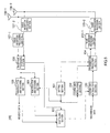
- FIG. 5 is a block diagram illustrating a configuration of the base station according to the present embodiment.
- base station 100 includes setting section 151, coding and modulation sections 152 and 153, transmission processing section 154, radio transmission processing sections 155-1 and 155-2, antennas 156-1 and 156-2, radio reception processing sections 157-1 and 157-2, reception processing section 158, demodulation and decoding sections 159 and 160 and scheduling section 161.
- control section 120 in FIG. 3 corresponds to setting section 151 and scheduling section 161 in FIG. 5 .
- Transmitting section 130 in FIG. 3 corresponds to coding and modulation sections 152 and 153, transmission processing section 154 and radio transmission processing sections 155-1 and 155-2 in FIG. 5 .
- Receiving section 140 in FIG. 3 corresponds to radio reception processing sections 157-1 and 157-2, reception processing section 158 and demodulation and decoding sections 159 and 160 in FIG. 5 .
- each resource of CSI-RS is used to measure one of a desired signal component and an interference component for one CSI report.
- Information on a non zero power CSI-RS resource in the measurement resource information includes parameters such as the number of antenna ports (Antenna Ports Count), CSI-RS configuration number (Resource Config) that identifies subcarrier and OFDM symbol positions in a subframe to which CSI-RS is mapped, transmission subframe (Subframe Config) made up of a transmission cycle and an offset.
- Information on the zero power CSI-RS resource includes parameters such as a no transmission CSI-RS configuration number list and a transmission subframe.
- Setting section 151 generates CSI reporting information.
- Information for identifying CSI which is a reporting target is set in the CSI reporting information.
- the CSI reporting information indicates association between the bits of trigger information and one set of one or a plurality of CSIs as a reporting target.
- Setting section 151 sets CSI reporting information so as to report a plurality of CSIs to each terminal 200 to perform CoMP.
- the measurement resource information and CSI reporting information are indicated from base station 100 to terminal 200 using, for example, RRC signaling and shared between base station 100 and terminal 200.
- setting section 151 When requesting aperiodic reporting, setting section 151 requests a CSI report, also generates trigger information for identifying a reporting target and outputs the trigger information to coding and modulation section 152 and demodulation and decoding section 160.
- Setting section 151 generates downlink resource allocation information which is information indicating resource allocation of PDSCH (Physical Downlink Shared Channel) for each terminal stored in PDCCH (Physical Downlink Control Channel) and outputs the downlink resource allocation information to transmission processing section 154.
- Setting section 151 also generates uplink resource allocation information which is information indicating PUCCH (Physical Uplink Control Channel) resources and outputs the uplink resource allocation information to coding and modulation section 152 and demodulation and decoding section 160.
- PDSCH Physical Downlink Shared Channel
- PDCCH Physical Downlink Control Channel
- Coding and modulation section 152 performs modulation processing on CSI-RS and outputs the modulated CSI-RS to transmission processing section 154.
- Coding and modulation section 152 performs coding processing and modulation processing on control information such as uplink resource allocation information, trigger information, generates PDCCH and outputs the generated PDCCH to transmission processing section 154.
- Coding and modulation section 153 performs coding processing and modulation processing on transmission data according to the control of scheduling section 161 and outputs the transmission data to transmission processing section 154.
- Transmission processing section 154 maps PDSCH based on the downlink resource allocation information.
- Transmission processing section 154 maps PDCCH.
- Transmission processing section 154 then forms a transmission signal through the mapping processing.
- the transmission signal is an OFDM signal
- transmission processing section 154 maps the modulated signal to resources indicated by the downlink resource allocation information, performs inverse fast Fourier transform (IFFT) processing to transform the modulated signal into a frequency-domain signal, adds a CP (Cyclic Prefix) thereto and thereby forms an OFDM signal.
- IFFT inverse fast Fourier transform
- Radio transmission processing sections 155-1 and 155-2 performs radio transmission processing (up-conversion, digital/analog conversion or the like) on the transmission signal and transmits the transmission signal to terminal 200 via antennas 156-1 and 156-2.
- Radio reception processing sections 157-1 and 157-2 perform radio reception processing (down-conversion, analog/digital conversion or the like) on radio signals received via antennas 156-1 and 156-2, and outputs the received signals obtained to reception processing section 158.
- Reception processing section 158 extracts PUSCH (Physical Uplink Shared Channel), PUCCH, SRS (Sounding Reference Signal) or the like mapped to resources of the received signals based on the uplink resource allocation information.
- Reception processing section 158 outputs PUSCH to demodulation and decoding section 159, outputs PUCCH to demodulation and decoding section 160, and outputs SRS to scheduling section 161.
- reception processing section 158 demultiplexes the received signal into CWs.
- reception processing section 158 deletes a CP from the received signal, performs fast Fourier transform (FFT) processing on the received signal to transform the signal into a time-domain signal.
- FFT fast Fourier transform
- Demodulation and decoding section 159 performs demodulation processing and decoding processing on PUSCH and obtains received data and CSI corresponding to aperiodic reporting. Demodulation and decoding section 159 extracts CSI corresponding to aperiodic reporting in a subframe 4 subframes after the subframe in which trigger information is transmitted.
- Demodulation and decoding section 160 performs demodulation processing and decoding processing on PDCCH and obtains control information including CSI corresponding to periodic reporting and ACK/NACK. Demodulation and decoding section 160 extracts CSI corresponding to periodic reporting in a defined subframe.
- Scheduling section 161 measures receiving quality of the uplink based on SRS, performs scheduling and link adaptation on the uplink and downlink respectively based on the measurement result, CSI and ACK/NACK, and controls coding and modulation section 153.
- scheduling section 161 performs scheduling and link adaptation assuming that the measured value of an interference component of the received CSI is not updated for a certain period after transmitting CSI-RS using an interference component measurement resource or that an interference component of the received CSI has been measured with respect to CSI-RS transmitted using an interference component measurement resource several transmissions before (CSI-RS other than the last transmitted CSI-RS).
- scheduling section 161 sets MCS (Modulation and Coding Scheme) by taking into account a possibility that a propagation environment may change for a period after an interference component is measured until CSI is generated.
- MCS Modulation and Coding Scheme
- a macro cell and a pico cell are formed by a single base station, but a macro cell and a pico cell may be formed of a plurality of base stations and both cells may be made to operate in coordination by sharing appropriate signals.
- radio transmission processing sections 155-1 and 155-2 antennas 156-1 and 156-2 and radio reception processing sections 157-1 and 157-2
- radio transmission processing section 155-1, radio reception processing section 157-1 and antenna 156-1 it is possible to use, for example, radio transmission processing section 155-1, radio reception processing section 157-1 and antenna 156-1 to form a macro cell and use radio transmission processing section 155-2, radio reception processing section 157-2 and antenna 156-2 to form a pico cell.
- FIG. 6 is a block diagram illustrating a configuration of the terminal according to the present embodiment.
- terminal 200 includes antenna 251, radio reception processing section 252, reception processing section 253, demodulation and decoding sections 254 and 255, CSI generating section 256, transmission control section 257, coding and modulation sections 258 and 259, transmission processing section 260 and radio transmission processing section 261.
- receiving section 220 in FIG. 4 corresponds to radio reception processing section 252, reception processing section 253 and demodulation and decoding sections 254 and 255 in FIG. 6 .
- Generation section 230 in FIG. 4 corresponds to CSI generating section 256 and transmission control section 257 in FIG. 6 .
- Transmitting section 240 in FIG. 4 corresponds to coding and modulation sections 258 and 259, transmission processing section 260 and radio transmission processing section 261 in FIG. 6 .
- Radio reception processing section 252 performs radio reception processing (down-conversion, analog/digital conversion or the like) on a radio signal received via antenna 251 and outputs the received signal obtained to reception processing section 253.
- Reception processing section 253 extracts PDCCH mapped to resources of the received signal. Note that when the received signal is an OFDM signal, reception processing section 253 also performs CP removing processing and FFT processing. Reception processing section 253 extracts PDSCH mapped to resources of the received signal based on the downlink resource allocation information. Reception processing section 253 outputs PDSCH to demodulation and decoding section 254 and outputs PDCCH to demodulation and decoding section 255 and CSI generating section 256.
- Demodulation and decoding section 254 performs demodulation processing and decoding processing on PDSCH and obtains received data. Demodulation and decoding section 254 performs error detection processing on the received data and outputs ACK/NACK corresponding to the error detection result to coding and modulation section 258.
- Demodulation and decoding section 255 performs demodulation processing and decoding processing on PDCCH and obtains control information such as uplink resources allocation control information and trigger information. Demodulation and decoding section 255 outputs the trigger information to CSI generating section 256 and outputs the uplink resources allocation control information to transmission control section 257.
- CSI generating section 256 measures a desired signal component of a non zero power CSI-RS resource and an interference component of a zero power CSI-RS resource indicated in measurement resource information and measures channel quality (e.g., SINR) based on the desired signal component and the interference component.
- channel quality e.g., SINR
- CSI generating section 256 measures a desired signal component of a non zero power CSI-RS resource indicated in the measurement resource information and an interference component of the zero power CSI-RS resource, and measures channel quality (e.g., SINR) based on the desired signal component and the interference component.
- CSI generating section 256 generates CSI based on the measurement result, outputs CSI corresponding to periodic reporting to coding and modulation section 258 and outputs CSI corresponding to aperiodic reporting to coding and modulation section 259.
- CSI generating section 256 does not measure any interference component for a certain period (e.g., for 4 subframes) after receiving the trigger information and measures channel quality from the measured interference component using an already measured interference component, for example, resources transmitted in the past corresponding to one transmission at a CSI-RS transmission interval.
- Transmission control section 257 identifies a resource to which the transmission signal is mapped based on the uplink resources allocation control information and outputs mapping resource information indicating this resource to transmission processing section 260. Transmission control section 257 also outputs MCS information included in the uplink resources allocation control information to coding and modulation section 259.
- Coding and modulation section 258 performs coding processing and modulation processing on ACK/NACK and CSI corresponding to periodic reporting and outputs PUCCH to transmission processing section 260.
- Coding and modulation section 259 performs coding processing and modulation processing on the transmission data and CSI corresponding to aperiodic reporting based on the MCS information and outputs PUSCH to transmission processing section 260.
- Transmission processing section 260 maps PUSCH, PUCCH and SRS based on the mapping resource information and forms a transmission signal.
- the transmission processing section maps the modulated signal to a resource indicated in the downlink resource allocation information, performs IFFT processing to transform the signal into a frequency-domain signal, and adds a CP to thereby form an OFDM signal.
- the transmission processing section generates a transmission signal using one codeword (CW) and in the case of MIMO transmission, the transmission processing section generates a transmission signal using two codewords.
- Radio transmission processing section 261 performs radio transmission processing (up-conversion, digital/analog conversion or the like) on the transmission signal and transmits a radio signal to base station 100 via antenna 251.
- FIG. 7 illustrates a case where a terminal (UE) is communicating with three base stations (TP-b, TP-c and TP-d) according to CoMP.
- a desired signal component measurement resource of base station TP-b is represented by NZP-b
- a desired signal component measurement resource of base station TP-c is represented by NZP-c
- a desired signal component measurement resource of base station TP-d is represented by NZP-d.
- an interference component measurement resource of a base station not included in CoMP is represented by ZP-a.
- FIG. 8 illustrates subframes (eNB tx) transmitted by coordinating base stations (TP-b, TP-c and TP-d), a CQI generation process (UE processing) performed by a terminal (UE) and subframes (UE tx) transmitted by the terminal (UE).
- eNB tx subframes transmitted by coordinating base stations (TP-b, TP-c and TP-d)
- UE processing a CQI generation process
- UE tx subframes transmitted by the terminal (UE).
- subframe 301 includes at least ZP-a and subframe 303 includes NZP-b, NZP-c, NZP-d and ZP-a.
- ZP-a is not included in subframes 302 and 304.
- the coordinating base stations (TP-b, TP-c and TP-d) transmit trigger information for instructing the terminal (UE) to report all CSIs (CSI1, CSI2 and CSI3) in subframe 303.
- CSI1 is CSI corresponding to base station TP-b
- CSI2 is CSI corresponding to base station TP-c
- CSI and CSI3 are CSIs corresponding to base station TP-d.
- the terminal (UE) measures an interference component using ZP-a in advance. Furthermore, in subframe 303, the terminal (UE) does not measure any interference component for a certain period (4 subframes up to subframe 311 in FIG. 8 ) after receiving trigger information.
- the terminal (UE) Upon receiving the trigger information, the terminal (UE) measures a desired signal component using NZP-b, NZP-c and NZP-d, measures channel quality using these resources and the interference component measured in advance, generates CSIs (CSI1, CSI2 and CSI3) indicating the measurement result and reports the CSIs in subframe 311. After that, the terminal (UE) measures the interference component using ZP-a included in subframe 303.
- the present embodiment can reduce the amount of processing required to generate one CSI compared to Release10 and reduce the time to generate each CSI.
- the present embodiment can also advance the timing of starting pipeline processing to generate CSI, and can thereby advance the completion of the processing all the more for CSIs generated in later stages of the pipeline.
- FIG. 8 the amount of processing (time) to generate CSI in CoMP is shown by a solid line arrow and the amount of processing (time) to generate CSI in Release10 is shown by a dotted line arrow.
- the present embodiment can process three or more CSIs for a period (4-subframe period) defined in Release10.
- the present embodiment it is possible to generate a plurality of (3 or more in the present embodiment) CSIs within a period predefined in Release10 by using an interference component measured in advance and thereby realize CoMP control that flexibly switches between base stations. Since the interference component has a large allowable delay, using an interference component measured in advance will not cause the accuracy of CSI to significantly deteriorate.
- the base station since the base station knows that the terminal generates CSI using an interference component measured in advance, it is possible to set MCS by taking into account the possibility that the propagation environment may change for a period after an interference component is measured until CSI is generated.
- Embodiment 2 will describe a method of generating CSI when there is a constraint that only up to two non zero power CSI-RS resources can be arranged in one subframe with reference to FIG. 7 and FIG. 9 .
- the configurations of a base station and a terminal in the present embodiment are the same as those shown in FIG. 3 to FIG. 6 .
- FIG. 9 illustrates subframes (eNB tx) transmitted by coordinating base stations (TP-b, TP-c, TP-d), a CQI generation process (UE processing) executed by a terminal (UE) and subframes (UE tx) transmitted by the terminal (UE).
- eNB tx subframes transmitted by coordinating base stations (TP-b, TP-c, TP-d)
- UE processing a CQI generation process
- UE tx subframes transmitted by the terminal (UE).
- subframes 301 and 303 include NZP-b, NZP-f and ZP-a and subframes 302 and 304 include NZP-c, NZP-d and ZP-e.
- coordinating base stations TP-b, TP-c and TP-d
- ZP-e and NZP-f are resources used in other terminals.
- the terminal (UE) need not measure any desired signal component or interference component using ZP-e and NZP-f.
- the terminal (UE) measures an interference component in advance using ZP-a.
- the terminal (UE) does not measure any interference component for a certain period (4 subframes up to subframe 311 in FIG. 8 ) after receiving trigger information.
- the terminal (UE) measures a desired signal component using NZP-b and then measures an interference component using ZP-a.
- the terminal (UE) measures channel quality using a desired signal component newly measure using NZP-b at the timing and an interference component measured in advance and generates CSI1.
- the terminal (UE) measures a desired signal component using NZP-c and NZP-d, measures channel quality using this desired signal component and an interference component measured in advance and generates CSI2 and CSI3.
- the terminal (UE) uses CSI2 and CSI3 generated in the stage of receiving subframe 302 and reports CSI1, CSI2 and CSI3 in subframe 311.
- the present embodiment even when there is a constraint on non zero power CSI-RS resources (up to two resources in the present embodiment) that can be arranged in one subframe, a plurality of (three or more in the present embodiment) CSIs can be generated within a period defined in Release 10, and it is thereby possible to realize CoMP control that flexibly switches between base stations.
- the present embodiment can substitute some of CSIs with those generated in advance, and can thereby reduce the amount of calculation compared to Embodiment 1. Note that the desired signal component used to generate CSIs as substitutes is measured within a range of allowable delays. For this reason, even when a desired signal component is measured in advance, this will not cause the accuracy of CSI to deteriorate significantly.
- occupying resources possessed by all coordinating base stations by one terminal may not always be the best. Transmitting a signal from some of the coordinating base stations to another terminal may result in an improved throughput of the entire cell or satisfy the allowable delay in the base stations.
- Embodiment 3 will describe a method of generating CSI when a base station instructs a terminal to use resources used to measure a desired signal component in reporting of one CSI to also measure an interference component in reporting of other CSIs with reference to FIG. 7 and FIG. 10 . That is, in the present embodiment, resources used to measure a desired signal component of CSI and resources used to measure an interference component of another CSI are the same.
- the configurations of a base station and a terminal in the present embodiment are the same as those shown in FIG. 3 to FIG. 6 .
- FIG. 10 shows subframes (eNB tx) transmitted by coordinating base stations (TP-b, TP-c and TP-d), CQI generation process (UE processing) executed by a terminal (UE) and subframes (UE tx) transmitted by the terminal (UE).
- eNB tx subframes transmitted by coordinating base stations (TP-b, TP-c and TP-d)
- CQI generation process UE processing
- UE tx subframes transmitted by the terminal (UE).
- subframes 301 and 303 include NZP-b, NZP-f and ZP-a and subframes 302 and 304 include NZP-c, NZP-d and ZP-e.
- the coordinating base stations (TP-b, TP-c and TP-d) transmit trigger information for instructing the terminal (UE) to report all CSIs (CSI1, CSI2 and CSI3) in subframe 303.
- the coordinating base stations (TP-b, TP-c and TP-d) instruct the terminal (UE) to use NZP-b to measure a desired signal component in CSI1 and to measure an interference component in CSI3.
- the terminal (UE) upon reception of subframe 301, the terminal (UE) measures an interference component using ZP-a and NZP-b in advance.
- the terminal (UE) does not measure any interference component for a certain period (4 subframes up to subframe 311 in FIG. 8 ) after receiving trigger information in subframe 303.
- the terminal (UE) measures a desired signal component using NZP-b and then measures an interference component.
- the terminal (UE) measures channel quality using a desired signal component newly measured using NZP-b at the timing and the interference component measured using ZP-a in advance, and generates CSI1.
- the terminal (UE) measures a desired signal component using NZP-c and measures channel quality using the interference component measured using ZP-a in advance, and generates CSI2.
- the terminal (UE) measures a desired signal component using NZP-d and measures channel quality using this desired signal component and the interference component measured using ZP-a and NZP-b in advance, and generates CSI3.
- the terminal (UE) reports CSI1, CSI2 and CSI3 in subframe 311 using CSI2 and CSI3 measured in the stage of receiving subframe 302.
- the terminal is instructed to use resources used to measure a desired signal component in reporting of one CSI to also measure an interference component in reporting of another CSI
- when generating CSI it is possible to substitute some of desired signal components with those measured in advance, and thereby reduce the amount of calculation compared to Embodiment 1. Note that since the desired signal component measured in advance is measured when receiving the last CSI-RS, channel quality is measured within a range of allowable delays of the desired signal component. For this reason, even when the desired signal component is measured in advance, this will not cause the accuracy of CSI to deteriorate significantly.
- the present invention is configured with hardware by way of example, but the invention may also be provided by software in cooperation with hardware.
- the functional blocks used in the descriptions of the embodiments are typically implemented as LSI devices, which are integrated circuits.
- the functional blocks may be formed as individual chips, or a part or all of the functional blocks may be integrated into a single chip.
- LSI is used herein, but the terms "IC,” “system LSI,” “super LSI” or “ultra LSI” may be used as well depending on the level of integration.
- circuit integration is not limited to LSI and may be achieved by dedicated circuitry or a general-purpose processor other than an LSI.
- a field programmable gate array FPGA
- reconfigurable processor which allows reconfiguration of connections and settings of circuit cells in LSI may be used.
- a radio communication terminal apparatus includes: a generation section that generates CSI (Channel State Information) using a desired signal component and an interference component; and a transmitting section that transmits the CSI, in which when receiving trigger information that requests a CSI report and generating the CSI, the generation section uses an interference component measured before receiving the trigger information.
- CSI Channel State Information
- the generation section when receiving the trigger information and generating the CSI, uses a desired signal component measured after receiving the trigger information.
- the generation section measures a desired signal component and an interference component using a resource indicated by resource information, in which the resource information indicates a resource to which a reference signal is mapped.
- the generation section uses a desired signal component of CSI to be reported that is measured before receiving the trigger information.
- the generation section measures a desired signal component using the resource after receiving the trigger information and measures an interference component using the interference component measured using the resource before receiving the trigger information.
- a radio communication base station apparatus includes: a transmitting section that transmits resource information indicating a resource to which a reference signal is mapped and trigger information requesting a CSI report; and a receiving section that receives CSI (Channel State Information) generated based on a desired signal component and an interference component measured using the resource for the trigger information, in which the CSI is generated based on an interference component measured before transmitting the trigger information.
- CSI Channel State Information
- the CSI is generated based on a desired signal component measured after transmitting the trigger information.
- a CSI generating method includes: measuring a desired signal component and an interference component; and generating CSI (Channel State Information) using the desired signal component and the interference component, in which, when trigger information requesting a CSI report is received and the CSI is generated, an interference component measured before receiving the trigger information is used.
- CSI Channel State Information
- the present invention is applicable to a mobile communication system which performs CoMP and in which a radio communication terminal apparatus reports CSI to a radio communication base station apparatus.
Abstract
Description
- The present invention relates to a radio communication terminal apparatus, a radio communication base station apparatus, and a CSI generating method, which are compliant with LTE-Advanced.
- In order to realize high-speed and large capacity communication between a radio communication base station apparatus (hereinafter, abbreviated as "base station") and a radio communication terminal apparatus (hereinafter, abbreviated as "terminal (UE: User Equipment)"), 3GPP (3rd Generation Partnership Project) has standardized LTE (Long Term Evolution) and LTE-Advanced (hereinafter, abbreviated as "LTE-A"), and is currently carrying out the standardization for further enhancement.
- LTE and LTE-A adopt OFDMA (Orthogonal Frequency Division Multiple Access) as a downlink communication scheme and adopt SC-FDMA (Single Carrier Frequency Division Multiple Access) as an uplink communication scheme.
- For frequency scheduling and link adaptation in OFDMA, a base station instructs each terminal to report CSI (Channel State Information) and allocates appropriate resources using CSI. CSI is information including downlink channel quality (SINR or the like) measured using a desired signal component and an interference component. CSI includes CQI (Channel Quality Indicator), PMI (Precoding Matrix Indicator) and RI (Rank Indicator) which indicates a spatial multiplexing number.
- LTE introduces two operations: operation of periodically reporting CSI (hereinafter referred to as "periodic reporting") and operation of aperiodically reporting CSI (hereinafter referred to as "aperiodic reporting"). In periodic reporting, a terminal reports CSI by arranging the CSI on an uplink control channel which is a defined uplink resource at predetermined intervals. On the other hand, in aperiodic reporting, a terminal reports CSI using a resource on a common data channel at predetermined timing after receiving an instruction (or request) to report CSI from a base station. Aperiodic reporting is instructed to the terminal when an uplink data channel is allocated using downlink control channel PDCCH.
- The terminal performs one measurement operation indicated in advance from the base station out of a plurality of measurement operations in one of periodic reporting and aperiodic reporting. This measurement operation is indicated from the base station to the terminal using a message for radio resource control (RRC signaling). Note that the base station can indicate different measurement operations for periodic reporting and aperiodic reporting to the terminal. For example, the base station may instruct the terminal to perform measurement operation to report RI, wideband PMI and wideband CQI in periodic reporting, and may instruct the terminal to perform measurement operation to report RI, wideband PMI, narrow band CQI in aperiodic reporting. In this case, periodic reporting may be used for rough link adaptation which is referenced when transmitting data with low urgency and aperiodic reporting may be used for detailed link adaptation which is referenced when transmitting data with high urgency.
- The terminal measures channel quality of a measurement target indicated in advance from the base station and reports CSI. LTE-A
Release 10 has added an operation for a terminal to report CSI for two types of measurement targets indicated in advance in periodic reporting. In addition, LTE-A Release10 has added an operation for a terminal to associate two types of measurement targets indicated in advance with timing at which a base station instructs the terminal to report CSI and for the terminal to report CSI for one of the measurement targets in aperiodic reporting. The two types of measurement targets have different situations of interference components. The two types of measurement targets are indicated to the terminal from the base station using RRC with a bitmap corresponding to 40 continuous subframes. - LTE-A
Release 10 also has introduced a concept of CA (Carrier Aggregation) and increased the number of bits of trigger information (CSI request field) indicating aperiodic reporting from 1 bit to 2 bits. As a result, the base station is enabled to instruct the terminal to report CSI and report one of a plurality of CCs (Component Carriers) or a plurality of CSIs as the CSI to be reported by the terminal. For example, the base station indicates CSIs of two CCs as CSI1 and CSI2 using bits of trigger information, "00" indicating that "CSI is not reported," "01" indicating that "only CSI1 is reported," "10" indicating that "only CSI2 is reported" and "11" indicating that "CSI1 and CSI2 are reported" in advance through, for example, RRC signaling. The base station then transmits trigger information with one of the above-described combinations of bits to the terminal, and can thereby indicate aperiodic reporting and also indicate CSI to be reported. - Thus, LTE-A Release10 provides a mechanism of simultaneously reporting two CSIs with the introduction of CA. To put it more specifically, in aperiodic reporting, the terminal transmits two CSIs using an uplink data signal after a lapse of a predetermined time (4 subframes) after reception of CSI reporting from the base station.
- Meanwhile, in
Release 11, which is the next version of LTE-A, CoMP (Coordinated Multi-Point) is being studied whereby a plurality of base stations cooperate to transmit signals to a terminal in a heterogeneous cell network (HetNet: Heterogeneous Network) in which there are a plurality of base stations having cover areas of different scales. HetNet is constructed of a macro cell (cell formed of a base station having large transmission power and coverage) and a pico cell (cell formed of a base station having small transmission power and coverage) within the macro cell. CoMP can reduce inter-cell interference and increase system throughput. - As CoMP schemes, 3GPP is studying mainly two CoMP schemes: (1) Coordinated beamforming (CB) and (2) Joint Transmission (JT).
- CB assumes that data transmitted to a predetermined terminal is possessed by only one cell. In the case of CB, a terminal regards as interference, signals transmitted from a base station of a neighboring cell that possesses no data addressed to the terminal. CB adopts a technique of reducing inter-cell interference by controlling transmission parameters. Examples of specific transmission parameters include precoding, transmission power, modulation scheme and coding rate. By appropriately controlling these parameters, it is possible to weaken signals from the interfering cell addressed to the corresponding terminal while strengthening signals from a desired cell.
- On the other hand, JT assumes that data transmitted to a predetermined terminal is possessed by a plurality of cells. Therefore, according to JT, respective base stations of the plurality of cells can simultaneously transmit signals to the corresponding terminal. Thus, unlike a conventional system, the terminal can handle a signal from a neighboring cell not as interference but as a desired signal, and therefore an SINR measured in the terminal is expected to improve. Especially by devising a method of generating precoding weights in a plurality of cells as operation within a network, it is possible to significantly improve the SINR measured in the terminal.
- For CoMP control, LTE-A
Release 11 provides a technique whereby a terminal measures channel quality of downlink to be controlled between a base station (hereinafter referred to as "coordinating base station") of each cell and the terminal, and reports CSI to the coordinating base stations in cell units. To put it more specifically, in aperiodic reporting, the terminal transmits the same number of CSIs as the coordinating base stations using uplink data signals after a lapse of a predetermined time after reception of an instruction of CSI reporting from the coordinating base station. - According to LTE-A Release11, a base station can indicate in advance, to a terminal, a resource to be measured to which a reference signal is mapped. As a reference signal, CSI-RS (Channel State Information-Reference Signal) is used. The base station indicates, to the terminal, information on a CSI-RS including a resource to which the CSI-RS is mapped using a message for radio resource control (RRC signaling) before the terminal performs CSI reporting.
-
FIGS. 1A to 1C are diagrams illustrating configuration examples of resources to which CSI-RSs are mapped. CSI-RSs are defined in 8-port, 4-port and 2-port configurations respectively according to the number of transmitting antenna ports of the base station.FIG. 1A illustrates a configuration example when the number of antenna ports is 8,FIG. 1B illustrates a configuration example when the number of antenna ports is 4, andFIG. 1C illustrates a configuration example when the number of antenna ports is 2. InFIGS. 1A to 1C , one subframe is made up of two resource blocks (RBs) each bundling 12 subcarriers. InFIGS. 1A to 1C , #i (0 to 19) represents a resource (2 REs (Resource Elements)) of two continuous OFDM symbols in the time domain within each subcarrier. In each resource (2 REs), CSI-RSs corresponding to two ports are code-multiplexed. - Each terminal acquires CSI-RS-related information from the base station in advance. Examples of the CSI-RS-related information include the number of antenna ports (Antenna Ports Count), CSI-RS configuration number (Resource Config:
number # 0 inFIG. 1 or the like) that identifies subcarriers within a subframe to which CSI-RS is mapped and OFDM symbol position, transmission subframe (Subframe Config) made up of transmission cycle and offset, and power ratio (p-C) between reference signals and data signals. - In
FIGS. 1A to 1C , CSI-RS configuration numbers are assigned in order in the time direction and in order in the frequency direction at the same point in time. As shown inFIGS. 1A to 1C , the same number is assigned to the start position (start position in numbering order) of a resource of each CSI-RS configuration number among CSI-RS configurations corresponding to the respective numbers of antenna ports. As shown inFIGS. 1A to 1C , a CSI-RS configuration with a small number of antenna ports forms a subset of a CSI-RS configuration with a large number of antenna ports. The same number is assigned to resources with the same start position. This makes it possible to cover all resources to be identified with minimum necessary numbers for each number of ports while using overlapping numbers. For example, CSI-RS config(O) with 2 ports shown inFIG. 1C can be identified as only resources (2 REs) corresponding to two ports from the start position of CSI-RS config(O) (8 REs) with 8 ports shown inFIG. 1A . Resources indicated in this way are resources used to measure desired signal components (hereinafter referred to as "desired signal component measurement resources") and called "non zero power CSI-RS resources." - LTE-
A Release 11 also provides a muting technique that causes a coordinating base station in a connected cell to transmit a no transmission signal (signal with amplitude 0) to measure CSI-RS transmitted from a coordinating base station in a peripheral cell. To put it more specifically, of resources withconfiguration numbers # 0 to #9 corresponding to four ports, resources to be designated as no transmission signals (resources to be muted) are indicated using a bitmap. Hereinafter, information indicating resources to be designated as no transmission signals will be referred to as "no transmission CSI-RS configuration number list (zeroTxPowerResourceConfigList)." - As an example, when configuration numbers (Resource Config) #1 and #2 are assumed to be no transmission signals, a no transmission CSI-RS configuration number list becomes {0, 1, 1, 0, 0, 0, 0, 0, 0, 0}. The base station indicates this no transmission CSI-RS configuration number list together with a transmission subframe (zeroTxPowerSubframeConfig) made up of a transmission cycle and offset to the terminal as in the case of the aforementioned CSI-RS, and the terminal can thereby identify resources which become no transmission signals in the corresponding subframe. The positions of the no transmission signals in the subframe corresponding to this example are #1 and #2 of CSI-RS shown in
FIG. 2 . - By associating a CSI-RS configuration of a coordinating base station of a peripheral cell with one CSI-RS configuration in the no transmission CSI-RS configuration number list, it is possible to avoid interference of a signal from the coordinating base station of the connected cell when measuring an SINR using the signal from the coordinating base station of the corresponding peripheral cell as a desired signal, and thereby improve accuracy of measuring CSI in the terminal. The resources indicated in this way are resources used to measure an interference component (hereinafter referred to as "interference component measurement resources") and are called "zero power CSI-RS resources."
- Each resource of CSI-RS is used to measure one of a desired signal component and an interference component for one CSI report. The base station may indicate only a non zero power CSI-RS resource, indicate only a zero power CSI-RS resource or indicate a combination of a non zero power CSI-RS resource and a zero power CSI-RS resource. Note that the base station may instruct the terminal to use resources used to measure a desired signal component in one CSI report to also measure an interference component in another CSI report.
- As described above, LTE-A Release10 provides the mechanism for simultaneously reporting two CSIs. On the other hand, a terminal simultaneously reports a plurality of CSIs to realize CoMP in LTE-A Release11 as well. In LTE-A Release11, unlike LTE-A Release10, the number of CSIs simultaneously generated is not limited to 2. For example, a base station of a macro cell, as a base station corresponding to a desired signal component, causes a terminal located in the vicinity of two pico cells within the macro cell area to measure SINRs of signals transmitted from three cells: a macro cell (TP-a), pico cell 1 (TP-b) and pico cell 2 (TP-c) and report the three CSIs. Thus, it is possible to transmit a signal from a base station having the best channel quality among the three cells, and thereby realize data transmission of high quality.
- However, as the number of simultaneously reported CSIs increases, the amount of processing required to generate CSI for updating the information thereof increases. For example, in the case where the terminal is caused to simultaneously report three CSIs, the amount of processing required to generate CSIs becomes at least 1.5 times compared to a case where two CSIs are simultaneously generated. For this reason, the terminal may not be able to complete processing of CSI reporting within a predetermined time (4 subframes) in aperiodic reporting. Thus, a technique for handling this increase in the amount of processing is necessary.
- A first conventional technique for handling the increase in the amount of processing may be to limit to a maximum of 2, the number of CSIs to be reported in one reporting unit of aperiodic reporting which is indicated by the base station using RRC signaling. It is thereby possible to make the amount of processing required to generate CSI equivalent to that in the related art.
- Moreover, as a second conventional technique for handling the increase in the amount of processing may be to lessen the allowable value of the processing time (see NPL 1). To put it more specifically, although CSI is conventionally reported after a lapse of 4 subframes after reception of an instruction of CSI reporting, CSI may be reported after a lapse of 6 subframes. This makes it possible to complete processing of CSI reporting without increasing the amount of processing per unit time.
- R1-122350, Renesas Mobile Europe Ltd., "On CSI feedback processing complexity in CoMP"
- However, according to the above-described first technique, the reporting operation is limited to a set value by RRC signaling, and so a base station as a reporting target can be switched only about one time every several seconds, which means that CSI is set quasi-statically, which diminishes the effect of CoMP that switching between base stations can be performed flexibly at intervals of several ms.
- According to the above-described second technique, the time from an instruction of CSI reporting to actual CSI reporting is extended. According to the above-described second technique, timing of CSI reporting is different between a Release10 compliant terminal and a Release11 compliant terminal, and therefore scheduling in the base station becomes complicated.
- An object of the present invention is to provide a radio communication terminal apparatus, a radio communication base station apparatus and a CSI generating method capable of generating a plurality of CSIs within a period defined in Release10 without deteriorating accuracy of CSI and realizing CoMP control whereby switching between base stations can be performed flexibly.
- As described above, a radio communication terminal apparatus according to an aspect of the present invention includes: a generation section that generates CSI (Channel State Information) using a desired signal component and an interference component; and a transmitting section that transmits the CSI, in which when receiving trigger information that requests a CSI report and generating the CSI, the generation section uses an interference component measured before receiving the trigger information.
- A radio communication base station apparatus according to an aspect of the present invention includes: a transmitting section that transmits resource information indicating a resource to which a reference signal is mapped and trigger information requesting a CSI report; and a receiving section that receives CSI (Channel State Information) generated based on a desired signal component and an interference component measured using the resource for the trigger information, in which the CSI is generated based on an interference component measured before transmitting the trigger information.
- A CSI generating method according to an aspect of the present invention includes: measuring a desired signal component and an interference component; and generating CSI (Channel State Information) using the desired signal component and the interference component, in which, when trigger information requesting a CSI report is received and the CSI is generated, an interference component measured before receiving the trigger information is used.
- According to the present invention, it is possible to generate a plurality of CSIs within a period defined in Release10 without deteriorating accuracy of CSI and realize CoMP control whereby switching between base stations can be performed flexibly.
-
-
FIG. 1 illustrates a configuration example of CSI-RS resources; -
FIG. 2 illustrates a configuration example of CSI-RS resources; -
FIG. 3 is a block diagram illustrating a main configuration of a base station according toEmbodiment 1 of the present invention; -
FIG. 4 is a block diagram illustrating a main configuration of a terminal according toEmbodiment 1 of the present invention; -
FIG. 5 is a block diagram illustrating a configuration of the base station according toEmbodiment 1 of the present invention; -
FIG. 6 is a block diagram illustrating a configuration of the terminal according toEmbodiment 1 of the present invention; -
FIG. 7 illustrates an example of a communication system according toEmbodiment 1 of the present invention; -
FIG. 8 illustrates a method of generating CSI by the terminal according toEmbodiment 1 of the present invention; -
FIG. 9 illustrates a method of generating CSI by a terminal according toEmbodiment 2 of the present invention; and -
FIG. 10 illustrates a method of generating CSI by a terminal according toEmbodiment 3 of the present invention. - Since a desired signal component follows instantaneous variations such that narrow band signals corresponding to subband CQI or the like tend to have lower time correlation or that it is necessary to observe a complex signal component for PMI calculation according to an instantaneous fading value, the desired signal component has a small allowable delay. On the other hand, since an interference component follows shadowing and traffic load such as an average power value of components that can be received as interference, the interference component has a large allowable delay. In this way, allowable control delays vary depending on the nature of channel information.
- Focusing attention on this aspect, the present invention is based on a concept that regarding an interference component, the accuracy of CSI would not significantly deteriorate even by using values measured in advance for resources transmitted in the past corresponding to one to several transmissions at CSI-RS transmission intervals.
- Hereinafter, embodiments of the present invention will be described in detail with reference to the accompanying drawings.
- A communication system according to
Embodiment 1 of the present invention includes base station 100 (seeFIGS. 3 and5 ) and terminal 200 (seeFIGS. 4 and6 ).Base station 100 is an LTE-A base station and terminal 200 is an LTE-A terminal. LTE-A-compliant radio communication is carried out betweenbase station 100 andterminal 200. -
FIG. 3 is a block diagram illustrating a main configuration of a base station according toEmbodiment 1 of the present invention.Base station 100 shown inFIG. 3 is mainly constructed ofcontrol section 120, transmittingsection 130 and receiving section140. -
Control section 120 generates information indicating positions or the like of desired signal component measurement resources and interference component measurement resources of CSI-RS (hereinafter referred to as "measurement resource information").Control section 120 requests that CSI should be reported in aperiodic reporting and also generates trigger information for identifying CSI to be reported by a terminal (hereinafter referred to as "reporting target").Control section 120 also generates information indicating a reporting target identified by trigger information (hereinafter referred to as "CSI reporting information"). For example, the CSI reporting information is information indicating the association between bits of trigger information and one set of one or a plurality of CSIs as a reporting target.Control section 120 performs scheduling and link adaptation based on CSI or the like. - Transmitting
section 130 transmits data signals and CSI-RSs to terminal 200 in subframe units. Transmittingsection 130 indicates CSI reporting information and measurement resource information toterminal 200 in advance. When requesting aperiodic reporting, transmittingsection 130 transmits trigger information toterminal 200. - Receiving section140 receives data signals from
terminal 200 in subframe units. Receivingsection 140 receives CSI reported fromterminal 200 at predetermined intervals or after a lapse of a certain period (e.g., after 4 subframes) after transmitting trigger information. - Here,
control section 120 performs scheduling and link adaptation assuming that a measured value of the received interference component of CSI will not be updated for a certain period after transmitting CSI-RS using interference component measurement resources or that the received interference component of CSI is measured for CSI-RS transmitted using interference component measurement resources several transmissions (CSI-RS other than the last transmitted CSI-RS) before. To put it more specifically,control section 120 sets MCS (Modulation and Coding Scheme) by taking into account a possibility that a propagation environment may change for a period after the interference component is measured until CSI is generated. -
Base station 100 indicates the CSI reporting information and measurement resource information toterminal 200 using, for example, RRC signaling.Base station 100 may also indicate the CSI reporting information and measurement resource information included in a CSI-RS-Config message.Base station 100 may set whether reporting is periodic reporting or aperiodic reporting forterminal 200 which is a CSI reporting target and indicate the set information included in a CQI-ReportConfig message. -
FIG. 4 is a block diagram illustrating a main configuration of a terminal according toEmbodiment 1 of the present invention.Terminal 200 shown inFIG. 4 is mainly constructed of receivingsection 220,generation section 230 and transmittingsection 240. - Receiving
section 220 receives data signals and CSI-RS frombase station 100 in subframe units. Before performing CSI reporting, receivingsection 220 receives CSI reporting information and measurement resource information in advance frombase station 100. Before performing aperiodic reporting, receivingsection 220 receives trigger information frombase station 100. - After receiving a predetermined interval or trigger information,
generation section 230 measures a desired signal component and interference component using CSI-RS resources indicated in the measurement resource information and generates CSI indicated in the CSI reporting information corresponding to the bits of trigger information using the CSI-RS resources indicated in the measurement resource information. - Here,
generation section 230 does not measure any interference component for a certain period after receiving trigger information (e.g., for 4 subframes) and measures channel quality using an already measured interference component. For example,generation section 230 measures channel quality using the last measured interference component. - Transmitting
section 240 transmits data signals tobase station 100 in subframe units. Transmittingsection 240 transmits the generated CSI tobase station 100. -
FIG. 5 is a block diagram illustrating a configuration of the base station according to the present embodiment. As shown inFIG. 5 ,base station 100 includes settingsection 151, coding andmodulation sections transmission processing section 154, radio transmission processing sections 155-1 and 155-2, antennas 156-1 and 156-2, radio reception processing sections 157-1 and 157-2,reception processing section 158, demodulation anddecoding sections scheduling section 161. - Note that
control section 120 inFIG. 3 corresponds to settingsection 151 andscheduling section 161 inFIG. 5 . Transmittingsection 130 inFIG. 3 corresponds to coding andmodulation sections transmission processing section 154 and radio transmission processing sections 155-1 and 155-2 inFIG. 5 . Receivingsection 140 inFIG. 3 corresponds to radio reception processing sections 157-1 and 157-2,reception processing section 158 and demodulation anddecoding sections FIG. 5 . - Setting
section 151 generates measurement resource information. As described above, each resource of CSI-RS is used to measure one of a desired signal component and an interference component for one CSI report. Information on a non zero power CSI-RS resource in the measurement resource information includes parameters such as the number of antenna ports (Antenna Ports Count), CSI-RS configuration number (Resource Config) that identifies subcarrier and OFDM symbol positions in a subframe to which CSI-RS is mapped, transmission subframe (Subframe Config) made up of a transmission cycle and an offset. Information on the zero power CSI-RS resource includes parameters such as a no transmission CSI-RS configuration number list and a transmission subframe. - Setting
section 151 generates CSI reporting information. Information for identifying CSI which is a reporting target is set in the CSI reporting information. For example, the CSI reporting information indicates association between the bits of trigger information and one set of one or a plurality of CSIs as a reporting target. Settingsection 151 sets CSI reporting information so as to report a plurality of CSIs to each terminal 200 to perform CoMP. - The measurement resource information and CSI reporting information are indicated from
base station 100 to terminal 200 using, for example, RRC signaling and shared betweenbase station 100 andterminal 200. - When requesting aperiodic reporting, setting
section 151 requests a CSI report, also generates trigger information for identifying a reporting target and outputs the trigger information to coding andmodulation section 152 and demodulation anddecoding section 160. - Setting
section 151 generates downlink resource allocation information which is information indicating resource allocation of PDSCH (Physical Downlink Shared Channel) for each terminal stored in PDCCH (Physical Downlink Control Channel) and outputs the downlink resource allocation information totransmission processing section 154. Settingsection 151 also generates uplink resource allocation information which is information indicating PUCCH (Physical Uplink Control Channel) resources and outputs the uplink resource allocation information to coding andmodulation section 152 and demodulation anddecoding section 160. - Coding and
modulation section 152 performs modulation processing on CSI-RS and outputs the modulated CSI-RS totransmission processing section 154. Coding andmodulation section 152 performs coding processing and modulation processing on control information such as uplink resource allocation information, trigger information, generates PDCCH and outputs the generated PDCCH totransmission processing section 154. Coding andmodulation section 153 performs coding processing and modulation processing on transmission data according to the control ofscheduling section 161 and outputs the transmission data totransmission processing section 154. -
Transmission processing section 154 maps PDSCH based on the downlink resource allocation information.Transmission processing section 154 maps PDCCH.Transmission processing section 154 then forms a transmission signal through the mapping processing. When the transmission signal is an OFDM signal,transmission processing section 154 maps the modulated signal to resources indicated by the downlink resource allocation information, performs inverse fast Fourier transform (IFFT) processing to transform the modulated signal into a frequency-domain signal, adds a CP (Cyclic Prefix) thereto and thereby forms an OFDM signal. - Radio transmission processing sections 155-1 and 155-2 performs radio transmission processing (up-conversion, digital/analog conversion or the like) on the transmission signal and transmits the transmission signal to
terminal 200 via antennas 156-1 and 156-2. - Radio reception processing sections 157-1 and 157-2 perform radio reception processing (down-conversion, analog/digital conversion or the like) on radio signals received via antennas 156-1 and 156-2, and outputs the received signals obtained to
reception processing section 158. -
Reception processing section 158 extracts PUSCH (Physical Uplink Shared Channel), PUCCH, SRS (Sounding Reference Signal) or the like mapped to resources of the received signals based on the uplink resource allocation information.Reception processing section 158 outputs PUSCH to demodulation anddecoding section 159, outputs PUCCH to demodulation anddecoding section 160, and outputs SRS toscheduling section 161. - When the received signal is a spatially multiplexed signal, that is, a signal transmitted with a plurality of codewords (CWs),
reception processing section 158 demultiplexes the received signal into CWs. On the other hand, when the received signal is an OFDM signal,reception processing section 158 deletes a CP from the received signal, performs fast Fourier transform (FFT) processing on the received signal to transform the signal into a time-domain signal. - Demodulation and
decoding section 159 performs demodulation processing and decoding processing on PUSCH and obtains received data and CSI corresponding to aperiodic reporting. Demodulation anddecoding section 159 extracts CSI corresponding to aperiodic reporting in asubframe 4 subframes after the subframe in which trigger information is transmitted. - Demodulation and
decoding section 160 performs demodulation processing and decoding processing on PDCCH and obtains control information including CSI corresponding to periodic reporting and ACK/NACK. Demodulation anddecoding section 160 extracts CSI corresponding to periodic reporting in a defined subframe. -
Scheduling section 161 measures receiving quality of the uplink based on SRS, performs scheduling and link adaptation on the uplink and downlink respectively based on the measurement result, CSI and ACK/NACK, and controls coding andmodulation section 153. - Here,
scheduling section 161 performs scheduling and link adaptation assuming that the measured value of an interference component of the received CSI is not updated for a certain period after transmitting CSI-RS using an interference component measurement resource or that an interference component of the received CSI has been measured with respect to CSI-RS transmitted using an interference component measurement resource several transmissions before (CSI-RS other than the last transmitted CSI-RS). To put it more specifically,scheduling section 161 sets MCS (Modulation and Coding Scheme) by taking into account a possibility that a propagation environment may change for a period after an interference component is measured until CSI is generated. - Note that the present embodiment has adopted the configuration in which a macro cell and a pico cell are formed by a single base station, but a macro cell and a pico cell may be formed of a plurality of base stations and both cells may be made to operate in coordination by sharing appropriate signals.
- In the present embodiment, of the plurality of radio transmission processing sections 155-1 and 155-2, antennas 156-1 and 156-2 and radio reception processing sections 157-1 and 157-2, it is possible to use, for example, radio transmission processing section 155-1, radio reception processing section 157-1 and antenna 156-1 to form a macro cell and use radio transmission processing section 155-2, radio reception processing section 157-2 and antenna 156-2 to form a pico cell.
-
FIG. 6 is a block diagram illustrating a configuration of the terminal according to the present embodiment. As shown inFIG. 6 ,terminal 200 includesantenna 251, radioreception processing section 252,reception processing section 253, demodulation anddecoding sections CSI generating section 256,transmission control section 257, coding andmodulation sections transmission processing section 260 and radiotransmission processing section 261. - Note that receiving
section 220 inFIG. 4 corresponds to radioreception processing section 252,reception processing section 253 and demodulation anddecoding sections FIG. 6 .Generation section 230 inFIG. 4 corresponds toCSI generating section 256 andtransmission control section 257 inFIG. 6 . Transmittingsection 240 inFIG. 4 corresponds to coding andmodulation sections transmission processing section 260 and radiotransmission processing section 261 inFIG. 6 . - Radio
reception processing section 252 performs radio reception processing (down-conversion, analog/digital conversion or the like) on a radio signal received viaantenna 251 and outputs the received signal obtained toreception processing section 253. -
Reception processing section 253 extracts PDCCH mapped to resources of the received signal. Note that when the received signal is an OFDM signal,reception processing section 253 also performs CP removing processing and FFT processing.Reception processing section 253 extracts PDSCH mapped to resources of the received signal based on the downlink resource allocation information.Reception processing section 253 outputs PDSCH to demodulation anddecoding section 254 and outputs PDCCH to demodulation anddecoding section 255 andCSI generating section 256. - Demodulation and
decoding section 254 performs demodulation processing and decoding processing on PDSCH and obtains received data. Demodulation anddecoding section 254 performs error detection processing on the received data and outputs ACK/NACK corresponding to the error detection result to coding andmodulation section 258. - Demodulation and
decoding section 255 performs demodulation processing and decoding processing on PDCCH and obtains control information such as uplink resources allocation control information and trigger information. Demodulation anddecoding section 255 outputs the trigger information toCSI generating section 256 and outputs the uplink resources allocation control information totransmission control section 257. - After a predetermined interval or reception of trigger information,
CSI generating section 256 measures a desired signal component of a non zero power CSI-RS resource and an interference component of a zero power CSI-RS resource indicated in measurement resource information and measures channel quality (e.g., SINR) based on the desired signal component and the interference component. Upon receiving trigger information, in order to generate CSI indicated in CSI reporting information corresponding to the trigger information bit,CSI generating section 256 measures a desired signal component of a non zero power CSI-RS resource indicated in the measurement resource information and an interference component of the zero power CSI-RS resource, and measures channel quality (e.g., SINR) based on the desired signal component and the interference component.CSI generating section 256 generates CSI based on the measurement result, outputs CSI corresponding to periodic reporting to coding andmodulation section 258 and outputs CSI corresponding to aperiodic reporting to coding andmodulation section 259. - Here,
CSI generating section 256 does not measure any interference component for a certain period (e.g., for 4 subframes) after receiving the trigger information and measures channel quality from the measured interference component using an already measured interference component, for example, resources transmitted in the past corresponding to one transmission at a CSI-RS transmission interval. -
Transmission control section 257 identifies a resource to which the transmission signal is mapped based on the uplink resources allocation control information and outputs mapping resource information indicating this resource totransmission processing section 260.Transmission control section 257 also outputs MCS information included in the uplink resources allocation control information to coding andmodulation section 259. - Coding and
modulation section 258 performs coding processing and modulation processing on ACK/NACK and CSI corresponding to periodic reporting and outputs PUCCH totransmission processing section 260. Coding andmodulation section 259 performs coding processing and modulation processing on the transmission data and CSI corresponding to aperiodic reporting based on the MCS information and outputs PUSCH totransmission processing section 260. -
Transmission processing section 260 maps PUSCH, PUCCH and SRS based on the mapping resource information and forms a transmission signal. Here, when the transmission signal is an OFDM signal, the transmission processing section maps the modulated signal to a resource indicated in the downlink resource allocation information, performs IFFT processing to transform the signal into a frequency-domain signal, and adds a CP to thereby form an OFDM signal. In the case of non-MIMO transmission, the transmission processing section generates a transmission signal using one codeword (CW) and in the case of MIMO transmission, the transmission processing section generates a transmission signal using two codewords. - Radio
transmission processing section 261 performs radio transmission processing (up-conversion, digital/analog conversion or the like) on the transmission signal and transmits a radio signal tobase station 100 viaantenna 251. - Next, a specific example of the method for generating CSI by
terminal 200 according to the present embodiment will be described with reference toFIG. 7 andFIG. 8 . An example inFIG. 7 illustrates a case where a terminal (UE) is communicating with three base stations (TP-b, TP-c and TP-d) according to CoMP. InFIG. 7 , a desired signal component measurement resource of base station TP-b is represented by NZP-b, a desired signal component measurement resource of base station TP-c is represented by NZP-c, and a desired signal component measurement resource of base station TP-d is represented by NZP-d. InFIG. 7 , an interference component measurement resource of a base station not included in CoMP is represented by ZP-a. -
FIG. 8 illustrates subframes (eNB tx) transmitted by coordinating base stations (TP-b, TP-c and TP-d), a CQI generation process (UE processing) performed by a terminal (UE) and subframes (UE tx) transmitted by the terminal (UE). - In the case of
FIG. 8 ,subframe 301 includes at least ZP-a andsubframe 303 includes NZP-b, NZP-c, NZP-d and ZP-a. ZP-a is not included insubframes subframe 303. Note that CSI1 is CSI corresponding to base station TP-b, CSI2 is CSI corresponding to base station TP-c, and CSI and CSI3 are CSIs corresponding to base station TP-d. - In this case, in a stage in which the terminal (UE) receives
subframe 301, the terminal (UE) measures an interference component using ZP-a in advance. Furthermore, insubframe 303, the terminal (UE) does not measure any interference component for a certain period (4 subframes up tosubframe 311 inFIG. 8 ) after receiving trigger information. - Upon receiving the trigger information, the terminal (UE) measures a desired signal component using NZP-b, NZP-c and NZP-d, measures channel quality using these resources and the interference component measured in advance, generates CSIs (CSI1, CSI2 and CSI3) indicating the measurement result and reports the CSIs in
subframe 311. After that, the terminal (UE) measures the interference component using ZP-a included insubframe 303. - As a result, the present embodiment can reduce the amount of processing required to generate one CSI compared to Release10 and reduce the time to generate each CSI. The present embodiment can also advance the timing of starting pipeline processing to generate CSI, and can thereby advance the completion of the processing all the more for CSIs generated in later stages of the pipeline. In
FIG. 8 , the amount of processing (time) to generate CSI in CoMP is shown by a solid line arrow and the amount of processing (time) to generate CSI in Release10 is shown by a dotted line arrow. - By this means, the present embodiment can process three or more CSIs for a period (4-subframe period) defined in Release10.
- As described above, according to the present embodiment, it is possible to generate a plurality of (3 or more in the present embodiment) CSIs within a period predefined in Release10 by using an interference component measured in advance and thereby realize CoMP control that flexibly switches between base stations. Since the interference component has a large allowable delay, using an interference component measured in advance will not cause the accuracy of CSI to significantly deteriorate.
- According to the present embodiment, since the base station knows that the terminal generates CSI using an interference component measured in advance, it is possible to set MCS by taking into account the possibility that the propagation environment may change for a period after an interference component is measured until CSI is generated.
-
Embodiment 2 will describe a method of generating CSI when there is a constraint that only up to two non zero power CSI-RS resources can be arranged in one subframe with reference toFIG. 7 andFIG. 9 . The configurations of a base station and a terminal in the present embodiment are the same as those shown inFIG. 3 to FIG. 6 . - As in the case of
FIG. 8 ,FIG. 9 illustrates subframes (eNB tx) transmitted by coordinating base stations (TP-b, TP-c, TP-d), a CQI generation process (UE processing) executed by a terminal (UE) and subframes (UE tx) transmitted by the terminal (UE). - In the case of
FIG. 9 ,subframes subframes subframe 303, coordinating base stations (TP-b, TP-c and TP-d) transmit trigger information for instructing the terminal (UE) to report all CSIs (CSI1, CSI2 and CSI3). ZP-e and NZP-f are resources used in other terminals. The terminal (UE) need not measure any desired signal component or interference component using ZP-e and NZP-f. - In this case, in the stage of receiving
subframe 301, the terminal (UE) measures an interference component in advance using ZP-a. Insubframe 303, the terminal (UE) does not measure any interference component for a certain period (4 subframes up tosubframe 311 inFIG. 8 ) after receiving trigger information. - In the stage of receiving
subframes - In the stage of receiving
subframes subframe 302 and reports CSI1, CSI2 and CSI3 insubframe 311. - Thus, in the present embodiment, even when there is a constraint that only up to two non zero power CSI-RS resources can be arranged in one subframe, three or more CSIs can be simultaneously processed within a period (4-subframe period) defined in
Release 10. - As described above, according to the present embodiment, even when there is a constraint on non zero power CSI-RS resources (up to two resources in the present embodiment) that can be arranged in one subframe, a plurality of (three or more in the present embodiment) CSIs can be generated within a period defined in
Release 10, and it is thereby possible to realize CoMP control that flexibly switches between base stations. When reporting CSI, the present embodiment can substitute some of CSIs with those generated in advance, and can thereby reduce the amount of calculation compared toEmbodiment 1. Note that the desired signal component used to generate CSIs as substitutes is measured within a range of allowable delays. For this reason, even when a desired signal component is measured in advance, this will not cause the accuracy of CSI to deteriorate significantly. - Depending on a propagation environment or traffic situation, occupying resources possessed by all coordinating base stations by one terminal may not always be the best. Transmitting a signal from some of the coordinating base stations to another terminal may result in an improved throughput of the entire cell or satisfy the allowable delay in the base stations.
- In view of this aspect,
Embodiment 3 will describe a method of generating CSI when a base station instructs a terminal to use resources used to measure a desired signal component in reporting of one CSI to also measure an interference component in reporting of other CSIs with reference toFIG. 7 andFIG. 10 . That is, in the present embodiment, resources used to measure a desired signal component of CSI and resources used to measure an interference component of another CSI are the same. The configurations of a base station and a terminal in the present embodiment are the same as those shown inFIG. 3 to FIG. 6 . In the present embodiment, as in the case ofEmbodiment 2, there is a constraint that only up to two non zero power CSI-RS resources can be arranged in one subframe. - As in the case of
FIG. 8 andFIG. 9 ,FIG. 10 shows subframes (eNB tx) transmitted by coordinating base stations (TP-b, TP-c and TP-d), CQI generation process (UE processing) executed by a terminal (UE) and subframes (UE tx) transmitted by the terminal (UE). - In the case of
FIG. 10 as in the case ofFIG. 9 ,subframes subframes subframe 303. - In
FIG. 10 , the coordinating base stations (TP-b, TP-c and TP-d) instruct the terminal (UE) to use NZP-b to measure a desired signal component in CSI1 and to measure an interference component in CSI3. - In this case, upon reception of
subframe 301, the terminal (UE) measures an interference component using ZP-a and NZP-b in advance. The terminal (UE) does not measure any interference component for a certain period (4 subframes up tosubframe 311 inFIG. 8 ) after receiving trigger information insubframe 303. - In the stage of receiving
subframes - In the stage of receiving
subframes subframes subframe 311 using CSI2 and CSI3 measured in the stage of receivingsubframe 302. - Thus, in the present embodiment, even in a case where the terminal is instructed to use resources used to measure a desired signal component in reporting of one CSI to also measure an interference component in reporting of another CSI, it is possible to simultaneously process three or more CSIs within a period (4-subframe period) defined in Release10.
- As described above, according to the present embodiment, even in a case where the terminal is instructed to use resources used to measure a desired signal component in reporting of one CSI to also measure an interference component in reporting of another CSI, it is possible to simultaneously process a plurality of (three or more in the present embodiment) CSIs within a period defined in Release10 and realize CoMP control that flexibly switches between base stations as in
Embodiments Embodiment 1. Note that since the desired signal component measured in advance is measured when receiving the last CSI-RS, channel quality is measured within a range of allowable delays of the desired signal component. For this reason, even when the desired signal component is measured in advance, this will not cause the accuracy of CSI to deteriorate significantly. - Each embodiment of the present invention has been described thus far.
- In the foregoing embodiments, the present invention is configured with hardware by way of example, but the invention may also be provided by software in cooperation with hardware.
- In addition, the functional blocks used in the descriptions of the embodiments are typically implemented as LSI devices, which are integrated circuits. The functional blocks may be formed as individual chips, or a part or all of the functional blocks may be integrated into a single chip. The term "LSI" is used herein, but the terms "IC," "system LSI," "super LSI" or "ultra LSI" may be used as well depending on the level of integration.
- In addition, the circuit integration is not limited to LSI and may be achieved by dedicated circuitry or a general-purpose processor other than an LSI. After fabrication of LSI, a field programmable gate array (FPGA), which is programmable, or a reconfigurable processor which allows reconfiguration of connections and settings of circuit cells in LSI may be used.
- Should a circuit integration technology replacing LSI appear as a result of advancements in semiconductor technology or other technologies derived from the technology, the functional blocks could be integrated using such a technology. Another possibility is the application of biotechnology and/or the like,
- As described above, a radio communication terminal apparatus according to the embodiments includes: a generation section that generates CSI (Channel State Information) using a desired signal component and an interference component; and a transmitting section that transmits the CSI, in which when receiving trigger information that requests a CSI report and generating the CSI, the generation section uses an interference component measured before receiving the trigger information.
- In the radio communication terminal apparatus according to the embodiments, when receiving the trigger information and generating the CSI, the generation section uses a desired signal component measured after receiving the trigger information.
- In the radio communication terminal apparatus according to the embodiments, the generation section measures a desired signal component and an interference component using a resource indicated by resource information, in which the resource information indicates a resource to which a reference signal is mapped.
- In the radio communication terminal apparatus according to the embodiments, when no resource exists for measuring a desired signal component of CSI to be reported in a subframe received at timing at which the trigger information is received, the generation section uses a desired signal component of CSI to be reported that is measured before receiving the trigger information.
- In the radio communication terminal apparatus the embodiments, when a resource used to measure a desired signal component of CSI and a resource used to measure an interference component of another CSI are the same, the generation section measures a desired signal component using the resource after receiving the trigger information and measures an interference component using the interference component measured using the resource before receiving the trigger information.
- A radio communication base station apparatus according to the embodiments includes: a transmitting section that transmits resource information indicating a resource to which a reference signal is mapped and trigger information requesting a CSI report; and a receiving section that receives CSI (Channel State Information) generated based on a desired signal component and an interference component measured using the resource for the trigger information, in which the CSI is generated based on an interference component measured before transmitting the trigger information.
- In the radio communication base station apparatus according to the embodiments, the CSI is generated based on a desired signal component measured after transmitting the trigger information.
- A CSI generating method according to the embodiments includes: measuring a desired signal component and an interference component; and generating CSI (Channel State Information) using the desired signal component and the interference component, in which, when trigger information requesting a CSI report is received and the CSI is generated, an interference component measured before receiving the trigger information is used.
- The disclosure of the specification, drawings and abstract in Japanese Patent Application No.
2012-173036 - The present invention is applicable to a mobile communication system which performs CoMP and in which a radio communication terminal apparatus reports CSI to a radio communication base station apparatus.
-
- 100
- Base station
- 120
- Control section
- 130
- Transmitting section
- 140
- Receiving section
- 151
- Setting section
- 152, 153
- Coding and modulation section
- 154
- Transmission processing section
- 155-1, 155-2
- Radio transmission processing section
- 156-1, 156-2
- Antenna
- 157-1, 157-2
- Radio reception processing section
- 158
- Reception processing section
- 159, 160
- Demodulation and decoding section
- 161
- Scheduling section
- 200
- Terminal
- 220
- Receiving section
- 230
- Generation section
- 240
- Transmitting section
- 251
- Antenna
- 252
- Radio reception processing section
- 253
- Reception processing section
- 254, 255
- Demodulation and decoding section
- 256
- CSI Generating section
- 257
- Transmission control section
- 258, 259
- Coding and modulation section
- 260
- Transmission processing section
- 261
- Radio transmission processing section
Claims (8)
- A radio communication terminal apparatus comprising:a generation section that generates CSI (Channel State Information) using a desired signal component and an interference component; anda transmitting section that transmits the CSI, whereinwhen receiving trigger information that requests a CSI report and generating the CSI, the generation section uses an interference component measured before receiving the trigger information.
- The radio communication terminal apparatus according to claim 1, wherein when receiving the trigger information and generating the CSI, the generation section uses a desired signal component measured after receiving the trigger information.
- The radio communication terminal apparatus according to claim 1, wherein the generation section measures the desired signal component and the interference component using a resource indicated by resource information, wherein the resource information indicates a resource to which a reference signal is mapped.
- The radio communication terminal apparatus according to claim 3, wherein when no resource exists for measuring a desired signal component of CSI to be reported in a subframe received at timing at which the trigger information is received, the generation section uses a desired signal component of CSI to be reported that is measured before receiving the trigger information.
- The radio communication terminal apparatus according to claim 3, wherein, when a resource used to measure a desired signal component of CSI and a resource used to measure an interference component of another CSI are the same, the generation section measures the desired signal component using the resource after receiving the trigger information and measures the interference component using the interference component measured using the resource before receiving the trigger information.
- A radio communication base station apparatus comprising:a transmitting section that transmits resource information indicating a resource to which a reference signal is mapped and trigger information requesting a CSI report; anda receiving section that receives CSI (Channel State Information) generated based on a desired signal component and an interference component measured using the resource for the trigger information, whereinthe CSI is generated based on an interference component measured before transmitting the trigger information.
- The radio communication base station apparatus according to claim 6 wherein the CSI is generated based on a desired signal component measured after transmitting the trigger information.
- A CSI generating method comprising:measuring a desired signal component and an interference component; andgenerating CSI (Channel State Information) using the desired signal component and the interference component, whereinwhen trigger information requesting a CSI report is received and the CSI is generated, an interference component measured before receiving the trigger information is used.
Priority Applications (1)
| Application Number | Priority Date | Filing Date | Title |
|---|---|---|---|
| EP19155493.0A EP3503617B1 (en) | 2012-08-03 | 2013-07-05 | Wireless communication terminal device, wireless communication base device, and method for generating csi |
Applications Claiming Priority (2)
| Application Number | Priority Date | Filing Date | Title |
|---|---|---|---|
| JP2012173036 | 2012-08-03 | ||
| PCT/JP2013/004198 WO2014020828A1 (en) | 2012-08-03 | 2013-07-05 | Wireless communication terminal device, wireless communication base device, and method for generating csi |
Related Child Applications (2)
| Application Number | Title | Priority Date | Filing Date |
|---|---|---|---|
| EP19155493.0A Division-Into EP3503617B1 (en) | 2012-08-03 | 2013-07-05 | Wireless communication terminal device, wireless communication base device, and method for generating csi |
| EP19155493.0A Division EP3503617B1 (en) | 2012-08-03 | 2013-07-05 | Wireless communication terminal device, wireless communication base device, and method for generating csi |
Publications (3)
| Publication Number | Publication Date |
|---|---|
| EP2882217A1 true EP2882217A1 (en) | 2015-06-10 |
| EP2882217A4 EP2882217A4 (en) | 2015-08-12 |
| EP2882217B1 EP2882217B1 (en) | 2019-05-01 |
Family
ID=50027543
Family Applications (2)
| Application Number | Title | Priority Date | Filing Date |
|---|---|---|---|
| EP19155493.0A Active EP3503617B1 (en) | 2012-08-03 | 2013-07-05 | Wireless communication terminal device, wireless communication base device, and method for generating csi |
| EP13824923.0A Active EP2882217B1 (en) | 2012-08-03 | 2013-07-05 | Wireless communication terminal device, wireless communication base device, and method for generating csi |
Family Applications Before (1)
| Application Number | Title | Priority Date | Filing Date |
|---|---|---|---|
| EP19155493.0A Active EP3503617B1 (en) | 2012-08-03 | 2013-07-05 | Wireless communication terminal device, wireless communication base device, and method for generating csi |
Country Status (5)
| Country | Link |
|---|---|
| US (2) | US9531518B2 (en) |
| EP (2) | EP3503617B1 (en) |
| JP (1) | JP6300105B2 (en) |
| TW (1) | TWI596972B (en) |
| WO (1) | WO2014020828A1 (en) |
Cited By (2)
| Publication number | Priority date | Publication date | Assignee | Title |
|---|---|---|---|---|
| WO2018031779A1 (en) * | 2016-08-11 | 2018-02-15 | Sharp Laboratories Of America, Inc. | User equipments, base stations and methods |
| US11201708B2 (en) | 2016-07-29 | 2021-12-14 | Asustek Computer Inc. | Method and apparatus for channel state information report for beam operation in a wireless communication system |
Families Citing this family (15)
| Publication number | Priority date | Publication date | Assignee | Title |
|---|---|---|---|---|
| KR101781854B1 (en) | 2010-02-04 | 2017-09-26 | 엘지전자 주식회사 | Method and apparatus of transmitting sounding reference signal |
| US10171218B2 (en) * | 2014-04-03 | 2019-01-01 | Telefonaktiebolaget Lm Ericsson (Publ) | Method for estimating signal quality of transmission to a user equipment from a transmission point |
| EP3139657B1 (en) | 2014-05-19 | 2019-03-20 | Huawei Technologies Co., Ltd. | Base station device, user equipment, and method for reporting channel state information |
| CN111212477B (en) * | 2014-06-13 | 2023-10-10 | 北京三星通信技术研究有限公司 | Data transmission method and device |
| US10122429B2 (en) * | 2015-01-16 | 2018-11-06 | Qualcomm Incorporated | Channel state information for enhanced carrier aggregation |
| US9743392B2 (en) | 2015-01-30 | 2017-08-22 | Motorola Mobility Llc | Method and apparatus for signaling aperiodic channel state indication reference signals for LTE operation |
| US10084577B2 (en) * | 2015-01-30 | 2018-09-25 | Motorola Mobility Llc | Method and apparatus for signaling aperiodic channel state indication reference signals for LTE operation |
| US20160277942A1 (en) * | 2015-03-17 | 2016-09-22 | Qualcomm Incorporated | Load-aware channel state reference signal transmission |
| EP3276849B1 (en) | 2015-03-27 | 2022-11-30 | Samsung Electronics Co., Ltd. | Resource allocation device and method in large-scale antenna system |
| US20160323901A1 (en) * | 2015-05-01 | 2016-11-03 | Lg Electronics Inc. | Method for channel measurement and report in wireless communication system and apparatus therefor |
| US11291022B2 (en) | 2016-07-26 | 2022-03-29 | Ntt Docomo, Inc. | User terminal and radio communication method |
| JP6912556B2 (en) * | 2016-09-29 | 2021-08-04 | パナソニック インテレクチュアル プロパティ コーポレーション オブ アメリカPanasonic Intellectual Property Corporation of America | User equipment, base stations, and wireless communication methods |
| US20220038194A1 (en) * | 2018-11-02 | 2022-02-03 | Ntt Docomo, Inc. | User terminal and radio communication method |
| US11689267B2 (en) * | 2019-05-03 | 2023-06-27 | Mediatek Inc. | Aperiodic CSI triggering in scenarios with multiple PDCCHs |
| US11356162B2 (en) | 2019-05-24 | 2022-06-07 | Mediatek Inc. | CSI reporting for multiple transmission points |
Family Cites Families (36)
| Publication number | Priority date | Publication date | Assignee | Title |
|---|---|---|---|---|
| JP2008067121A (en) | 2006-09-08 | 2008-03-21 | Iwatsu Electric Co Ltd | Automatic channel determination method and apparatus |
| KR100966566B1 (en) | 2009-01-29 | 2010-06-29 | 엘지전자 주식회사 | Signal transmission scheme for efficient management of common e-dch |
| ES2368385T3 (en) * | 2009-01-29 | 2011-11-16 | Lg Electronics Inc. | SIGNAL TRANSMISSION SCHEME FOR EFFECTIVE MANAGEMENT OF THE COMMON IMPROVED DEDICATED CHANNEL. |
| EP2439997B1 (en) * | 2009-06-02 | 2019-08-28 | Sun Patent Trust | Wireless communication apparatus and wireless communication method |
| US9209933B2 (en) * | 2009-06-11 | 2015-12-08 | Qualcomm Incorporated | Method and apparatus for dispatching a channel quality indicator feedback in multicarrier system |
| KR20120037948A (en) * | 2009-07-21 | 2012-04-20 | 엘지전자 주식회사 | Apparatus and method for transmitting channel state information in a wireless communication system |
| EP2765730A3 (en) * | 2010-01-08 | 2015-04-15 | Interdigital Patent Holdings, Inc. | Channel state information transmission for multiple carriers |
| CA2784034C (en) * | 2010-01-18 | 2018-05-22 | Lg Electronics Inc. | A method and an apparatus for providing channel quality information in a wireless communication system |
| US8305987B2 (en) | 2010-02-12 | 2012-11-06 | Research In Motion Limited | Reference signal for a coordinated multi-point network implementation |
| US8638684B2 (en) * | 2010-04-05 | 2014-01-28 | Qualcomm | Aperiodic channel state information request in wireless communication |
| US9337954B2 (en) * | 2010-07-28 | 2016-05-10 | Qualcomm Incorporated | Protocol for channel state information feedback |
| KR101875609B1 (en) * | 2010-09-26 | 2018-08-02 | 엘지전자 주식회사 | Method and apparatus for efficient feedback in a wireless communication system supporting multiple antenna |
| US9014024B2 (en) * | 2010-10-04 | 2015-04-21 | Qualcomm Incorporated | Devices for determining a reference subframe and determining a mode |
| US9100868B2 (en) * | 2010-10-05 | 2015-08-04 | Cellular Communications Equipment Llc | Channel state information measurement and reporting |
| US9591499B2 (en) * | 2010-11-05 | 2017-03-07 | Interdigital Patent Holdings, Inc. | WTRU measurements handling to mitigate in-device interference |
| KR101876884B1 (en) * | 2010-11-09 | 2018-07-10 | 텔레폰악티에볼라겟엘엠에릭슨(펍) | Method and arrangement for reporting channel state information in a telecommunication system |
| ES2788301T3 (en) * | 2010-11-17 | 2020-10-21 | Lg Electronics Inc | Method and device for periodically reporting channel status information in a wireless connection system |
| KR101763751B1 (en) * | 2011-01-11 | 2017-08-02 | 삼성전자 주식회사 | Method and appratus of activating/deactivating secondary carriers in mobile communication system using carrier aggregation |
| US8995400B2 (en) * | 2011-02-11 | 2015-03-31 | Qualcomm Incorporated | Method and apparatus for enabling channel and interference estimations in macro/RRH system |
| JP5481410B2 (en) | 2011-02-18 | 2014-04-23 | 日立建機株式会社 | Liquid property identification device and liquid storage tank equipped with the device |
| US9673945B2 (en) * | 2011-02-18 | 2017-06-06 | Qualcomm Incorporated | Implicitly linking aperiodic channel state information (A-CSI) reports to CSI-reference signal (CSI-RS) resources |
| EP2719101B1 (en) * | 2011-06-10 | 2017-11-22 | LG Electronics Inc. | Method and apparatus for transmitting aperiodic channel state information in wireless communication system |
| JP6026415B2 (en) * | 2011-08-05 | 2016-11-16 | パナソニック インテレクチュアル プロパティ コーポレーション オブ アメリカPanasonic Intellectual Property Corporation of America | Terminal, transmission apparatus, reception quality report method, and reception method |
| WO2013055147A2 (en) * | 2011-10-14 | 2013-04-18 | 엘지전자 주식회사 | Method and device for transmitting channel state information in wireless communication system |
| PT2777198E (en) * | 2011-11-09 | 2016-03-01 | Ericsson Telefon Ab L M | Csi reporting for a set of csi-rs resources |
| US9912439B2 (en) * | 2011-11-10 | 2018-03-06 | Qualcomm Incorporated | Method and apparatus for sending channel state information using subframe-dependent control channel formats |
| US9008585B2 (en) * | 2012-01-30 | 2015-04-14 | Futurewei Technologies, Inc. | System and method for wireless communications measurements and CSI feedback |
| US9621318B2 (en) * | 2012-02-01 | 2017-04-11 | Samsung Electronics Co., Ltd | Method and device for transmitting and receiving channel state information in downlink coordinated multi-point system |
| US9602183B2 (en) * | 2012-03-14 | 2017-03-21 | Lg Electronics Inc. | Method and apparatus for reporting channel state information in wireless communication system |
| US9973955B2 (en) * | 2012-03-16 | 2018-05-15 | Futurewei Technologies, Inc. | Systems and methods for reference signals and CSI feedback |
| US9124330B2 (en) * | 2012-04-06 | 2015-09-01 | Samsung Electronics Co., Ltd. | Channel state information transmission/reception method and apparatus of downlink coordinated multi-point communication system |
| US11546787B2 (en) * | 2012-05-09 | 2023-01-03 | Samsung Electronics Co., Ltd. | CSI definitions and feedback modes for coordinated multi-point transmission |
| EP3444994B1 (en) * | 2012-05-10 | 2020-02-12 | Telefonaktiebolaget LM Ericsson (publ) | Methods and arrangements for csi reporting |
| US9537638B2 (en) * | 2012-05-11 | 2017-01-03 | Qualcomm Incorporated | Method and apparatus for performing coordinated multipoint feedback under multiple channel and interference assumptions |
| US9106386B2 (en) * | 2012-08-03 | 2015-08-11 | Intel Corporation | Reference signal configuration for coordinated multipoint |
| US10098020B2 (en) * | 2012-08-03 | 2018-10-09 | Intel Corporation | Techniques for sending or receiving channel state information reports associated with a coordinated multi-point scheme |
-
2013
- 2013-07-05 WO PCT/JP2013/004198 patent/WO2014020828A1/en active Application Filing
- 2013-07-05 US US14/415,125 patent/US9531518B2/en active Active
- 2013-07-05 EP EP19155493.0A patent/EP3503617B1/en active Active
- 2013-07-05 JP JP2014527962A patent/JP6300105B2/en active Active
- 2013-07-05 EP EP13824923.0A patent/EP2882217B1/en active Active
- 2013-07-12 TW TW102125084A patent/TWI596972B/en active
-
2016
- 2016-11-17 US US15/354,128 patent/US9806866B2/en active Active
Cited By (3)
| Publication number | Priority date | Publication date | Assignee | Title |
|---|---|---|---|---|
| US11201708B2 (en) | 2016-07-29 | 2021-12-14 | Asustek Computer Inc. | Method and apparatus for channel state information report for beam operation in a wireless communication system |
| US11652592B2 (en) | 2016-07-29 | 2023-05-16 | Asustek Computer Inc. | Method and apparatus for channel state information report for beam operation in a wireless communication system |
| WO2018031779A1 (en) * | 2016-08-11 | 2018-02-15 | Sharp Laboratories Of America, Inc. | User equipments, base stations and methods |
Also Published As
| Publication number | Publication date |
|---|---|
| US9531518B2 (en) | 2016-12-27 |
| TWI596972B (en) | 2017-08-21 |
| JPWO2014020828A1 (en) | 2016-07-21 |
| EP2882217B1 (en) | 2019-05-01 |
| US20170070331A1 (en) | 2017-03-09 |
| TW201410053A (en) | 2014-03-01 |
| EP2882217A4 (en) | 2015-08-12 |
| US20150180634A1 (en) | 2015-06-25 |
| US9806866B2 (en) | 2017-10-31 |
| JP6300105B2 (en) | 2018-03-28 |
| EP3503617B1 (en) | 2020-07-01 |
| WO2014020828A1 (en) | 2014-02-06 |
| EP3503617A1 (en) | 2019-06-26 |
Similar Documents
| Publication | Publication Date | Title |
|---|---|---|
| US9806866B2 (en) | Wireless communication terminal device, wireless communication base device, and method for generating CSI | |
| US11728953B2 (en) | Reference signal reception and CQI computation method and wireless communication apparatus | |
| CN110945799B (en) | Method for reporting channel state information in wireless communication system and apparatus therefor | |
| US20210336661A1 (en) | Method and apparatus for transmitting and receiving channel state information in wireless communication system | |
| CN110431759B (en) | Method for reporting channel state information in wireless communication system and apparatus therefor | |
| CN110574314B (en) | Method for reporting channel state information in wireless communication system and apparatus therefor | |
| US9526094B2 (en) | Terminal, base station, transmission method, and reception method | |
| EP3444961B1 (en) | Channel state information transmission/reception method and apparatus for use in wireless communication system | |
| EP2439997B1 (en) | Wireless communication apparatus and wireless communication method | |
| US9628235B2 (en) | Communication system, base station apparatus, terminal apparatus, and communication method | |
| CN116318301A (en) | Method for performing beam restoration in wireless communication system and apparatus therefor | |
| EP2677828B1 (en) | Base station device, mobile terminal device, and communication control method | |
| US9749108B2 (en) | Terminal, base station, transmission method, and reception method | |
| KR20140108793A (en) | Method and apparatus for transmitting and receivintg feedback information in mobile communication system based on full dimension mimo | |
| EP3355608A1 (en) | User terminal, wireless base station, and wireless communication method | |
| US10097251B2 (en) | Wireless communication system, method for transmitting information of user equipment, method for receiving information of base station, and user equipment and base station thereof | |
| US20210385810A1 (en) | Base station, terminal apparatus, method, program, and recording medium | |
| US9392520B2 (en) | Base station apparatus, mobile terminal apparatus and communication control method | |
| EP3496508B1 (en) | User terminal and wireless communication method | |
| JP2013031210A (en) | Mobile communication system |
Legal Events
| Date | Code | Title | Description |
|---|---|---|---|
| PUAI | Public reference made under article 153(3) epc to a published international application that has entered the european phase |
Free format text: ORIGINAL CODE: 0009012 |
|
| 17P | Request for examination filed |
Effective date: 20150115 |
|
| AK | Designated contracting states |
Kind code of ref document: A1 Designated state(s): AL AT BE BG CH CY CZ DE DK EE ES FI FR GB GR HR HU IE IS IT LI LT LU LV MC MK MT NL NO PL PT RO RS SE SI SK SM TR |
|
| AX | Request for extension of the european patent |
Extension state: BA ME |
|
| RA4 | Supplementary search report drawn up and despatched (corrected) |
Effective date: 20150709 |
|
| RIC1 | Information provided on ipc code assigned before grant |
Ipc: H04B 7/06 20060101ALI20150703BHEP Ipc: H04B 17/24 20150101ALI20150703BHEP Ipc: H04W 72/08 20090101ALI20150703BHEP Ipc: H04B 17/345 20150101ALI20150703BHEP Ipc: H04B 17/309 20150101ALI20150703BHEP Ipc: H04B 17/318 20150101ALI20150703BHEP Ipc: H04W 24/10 20090101AFI20150703BHEP Ipc: H04W 28/16 20090101ALI20150703BHEP Ipc: H04B 7/02 20060101ALI20150703BHEP Ipc: H04L 5/00 20060101ALI20150703BHEP |
|
| DAX | Request for extension of the european patent (deleted) | ||
| RAP1 | Party data changed (applicant data changed or rights of an application transferred) |
Owner name: SUN PATENT TRUST |
|
| STAA | Information on the status of an ep patent application or granted ep patent |
Free format text: STATUS: EXAMINATION IS IN PROGRESS |
|
| 17Q | First examination report despatched |
Effective date: 20171214 |
|
| GRAP | Despatch of communication of intention to grant a patent |
Free format text: ORIGINAL CODE: EPIDOSNIGR1 |
|
| STAA | Information on the status of an ep patent application or granted ep patent |
Free format text: STATUS: GRANT OF PATENT IS INTENDED |
|
| INTG | Intention to grant announced |
Effective date: 20181211 |
|
| GRAS | Grant fee paid |
Free format text: ORIGINAL CODE: EPIDOSNIGR3 |
|
| GRAA | (expected) grant |
Free format text: ORIGINAL CODE: 0009210 |
|
| STAA | Information on the status of an ep patent application or granted ep patent |
Free format text: STATUS: THE PATENT HAS BEEN GRANTED |
|
| AK | Designated contracting states |
Kind code of ref document: B1 Designated state(s): AL AT BE BG CH CY CZ DE DK EE ES FI FR GB GR HR HU IE IS IT LI LT LU LV MC MK MT NL NO PL PT RO RS SE SI SK SM TR |
|
| REG | Reference to a national code |
Ref country code: GB Ref legal event code: FG4D |
|
| REG | Reference to a national code |
Ref country code: CH Ref legal event code: EP Ref country code: AT Ref legal event code: REF Ref document number: 1128583 Country of ref document: AT Kind code of ref document: T Effective date: 20190515 |
|
| REG | Reference to a national code |
Ref country code: DE Ref legal event code: R096 Ref document number: 602013054752 Country of ref document: DE |
|
| REG | Reference to a national code |
Ref country code: IE Ref legal event code: FG4D |
|
| REG | Reference to a national code |
Ref country code: NL Ref legal event code: MP Effective date: 20190501 |
|
| REG | Reference to a national code |
Ref country code: LT Ref legal event code: MG4D |
|
| PG25 | Lapsed in a contracting state [announced via postgrant information from national office to epo] |
Ref country code: FI Free format text: LAPSE BECAUSE OF FAILURE TO SUBMIT A TRANSLATION OF THE DESCRIPTION OR TO PAY THE FEE WITHIN THE PRESCRIBED TIME-LIMIT Effective date: 20190501 Ref country code: SE Free format text: LAPSE BECAUSE OF FAILURE TO SUBMIT A TRANSLATION OF THE DESCRIPTION OR TO PAY THE FEE WITHIN THE PRESCRIBED TIME-LIMIT Effective date: 20190501 Ref country code: NL Free format text: LAPSE BECAUSE OF FAILURE TO SUBMIT A TRANSLATION OF THE DESCRIPTION OR TO PAY THE FEE WITHIN THE PRESCRIBED TIME-LIMIT Effective date: 20190501 Ref country code: ES Free format text: LAPSE BECAUSE OF FAILURE TO SUBMIT A TRANSLATION OF THE DESCRIPTION OR TO PAY THE FEE WITHIN THE PRESCRIBED TIME-LIMIT Effective date: 20190501 Ref country code: LT Free format text: LAPSE BECAUSE OF FAILURE TO SUBMIT A TRANSLATION OF THE DESCRIPTION OR TO PAY THE FEE WITHIN THE PRESCRIBED TIME-LIMIT Effective date: 20190501 Ref country code: AL Free format text: LAPSE BECAUSE OF FAILURE TO SUBMIT A TRANSLATION OF THE DESCRIPTION OR TO PAY THE FEE WITHIN THE PRESCRIBED TIME-LIMIT Effective date: 20190501 Ref country code: HR Free format text: LAPSE BECAUSE OF FAILURE TO SUBMIT A TRANSLATION OF THE DESCRIPTION OR TO PAY THE FEE WITHIN THE PRESCRIBED TIME-LIMIT Effective date: 20190501 Ref country code: PT Free format text: LAPSE BECAUSE OF FAILURE TO SUBMIT A TRANSLATION OF THE DESCRIPTION OR TO PAY THE FEE WITHIN THE PRESCRIBED TIME-LIMIT Effective date: 20190901 Ref country code: NO Free format text: LAPSE BECAUSE OF FAILURE TO SUBMIT A TRANSLATION OF THE DESCRIPTION OR TO PAY THE FEE WITHIN THE PRESCRIBED TIME-LIMIT Effective date: 20190801 |
|
| PG25 | Lapsed in a contracting state [announced via postgrant information from national office to epo] |
Ref country code: LV Free format text: LAPSE BECAUSE OF FAILURE TO SUBMIT A TRANSLATION OF THE DESCRIPTION OR TO PAY THE FEE WITHIN THE PRESCRIBED TIME-LIMIT Effective date: 20190501 Ref country code: GR Free format text: LAPSE BECAUSE OF FAILURE TO SUBMIT A TRANSLATION OF THE DESCRIPTION OR TO PAY THE FEE WITHIN THE PRESCRIBED TIME-LIMIT Effective date: 20190802 Ref country code: RS Free format text: LAPSE BECAUSE OF FAILURE TO SUBMIT A TRANSLATION OF THE DESCRIPTION OR TO PAY THE FEE WITHIN THE PRESCRIBED TIME-LIMIT Effective date: 20190501 Ref country code: BG Free format text: LAPSE BECAUSE OF FAILURE TO SUBMIT A TRANSLATION OF THE DESCRIPTION OR TO PAY THE FEE WITHIN THE PRESCRIBED TIME-LIMIT Effective date: 20190801 |
|
| REG | Reference to a national code |
Ref country code: AT Ref legal event code: MK05 Ref document number: 1128583 Country of ref document: AT Kind code of ref document: T Effective date: 20190501 |
|
| PG25 | Lapsed in a contracting state [announced via postgrant information from national office to epo] |
Ref country code: IS Free format text: LAPSE BECAUSE OF FAILURE TO SUBMIT A TRANSLATION OF THE DESCRIPTION OR TO PAY THE FEE WITHIN THE PRESCRIBED TIME-LIMIT Effective date: 20190901 |
|
| PG25 | Lapsed in a contracting state [announced via postgrant information from national office to epo] |
Ref country code: CZ Free format text: LAPSE BECAUSE OF FAILURE TO SUBMIT A TRANSLATION OF THE DESCRIPTION OR TO PAY THE FEE WITHIN THE PRESCRIBED TIME-LIMIT Effective date: 20190501 Ref country code: RO Free format text: LAPSE BECAUSE OF FAILURE TO SUBMIT A TRANSLATION OF THE DESCRIPTION OR TO PAY THE FEE WITHIN THE PRESCRIBED TIME-LIMIT Effective date: 20190501 Ref country code: SK Free format text: LAPSE BECAUSE OF FAILURE TO SUBMIT A TRANSLATION OF THE DESCRIPTION OR TO PAY THE FEE WITHIN THE PRESCRIBED TIME-LIMIT Effective date: 20190501 Ref country code: AT Free format text: LAPSE BECAUSE OF FAILURE TO SUBMIT A TRANSLATION OF THE DESCRIPTION OR TO PAY THE FEE WITHIN THE PRESCRIBED TIME-LIMIT Effective date: 20190501 Ref country code: DK Free format text: LAPSE BECAUSE OF FAILURE TO SUBMIT A TRANSLATION OF THE DESCRIPTION OR TO PAY THE FEE WITHIN THE PRESCRIBED TIME-LIMIT Effective date: 20190501 Ref country code: EE Free format text: LAPSE BECAUSE OF FAILURE TO SUBMIT A TRANSLATION OF THE DESCRIPTION OR TO PAY THE FEE WITHIN THE PRESCRIBED TIME-LIMIT Effective date: 20190501 |
|
| REG | Reference to a national code |
Ref country code: DE Ref legal event code: R097 Ref document number: 602013054752 Country of ref document: DE |
|
| PG25 | Lapsed in a contracting state [announced via postgrant information from national office to epo] |
Ref country code: IT Free format text: LAPSE BECAUSE OF FAILURE TO SUBMIT A TRANSLATION OF THE DESCRIPTION OR TO PAY THE FEE WITHIN THE PRESCRIBED TIME-LIMIT Effective date: 20190501 Ref country code: SM Free format text: LAPSE BECAUSE OF FAILURE TO SUBMIT A TRANSLATION OF THE DESCRIPTION OR TO PAY THE FEE WITHIN THE PRESCRIBED TIME-LIMIT Effective date: 20190501 Ref country code: MC Free format text: LAPSE BECAUSE OF FAILURE TO SUBMIT A TRANSLATION OF THE DESCRIPTION OR TO PAY THE FEE WITHIN THE PRESCRIBED TIME-LIMIT Effective date: 20190501 |
|
| REG | Reference to a national code |
Ref country code: CH Ref legal event code: PL |
|
| PLBE | No opposition filed within time limit |
Free format text: ORIGINAL CODE: 0009261 |
|
| STAA | Information on the status of an ep patent application or granted ep patent |
Free format text: STATUS: NO OPPOSITION FILED WITHIN TIME LIMIT |
|
| PG25 | Lapsed in a contracting state [announced via postgrant information from national office to epo] |
Ref country code: TR Free format text: LAPSE BECAUSE OF FAILURE TO SUBMIT A TRANSLATION OF THE DESCRIPTION OR TO PAY THE FEE WITHIN THE PRESCRIBED TIME-LIMIT Effective date: 20190501 |
|
| 26N | No opposition filed |
Effective date: 20200204 |
|
| REG | Reference to a national code |
Ref country code: BE Ref legal event code: MM Effective date: 20190731 |
|
| GBPC | Gb: european patent ceased through non-payment of renewal fee |
Effective date: 20190801 |
|
| PG25 | Lapsed in a contracting state [announced via postgrant information from national office to epo] |
Ref country code: PL Free format text: LAPSE BECAUSE OF FAILURE TO SUBMIT A TRANSLATION OF THE DESCRIPTION OR TO PAY THE FEE WITHIN THE PRESCRIBED TIME-LIMIT Effective date: 20190501 |
|
| PG25 | Lapsed in a contracting state [announced via postgrant information from national office to epo] |
Ref country code: CH Free format text: LAPSE BECAUSE OF NON-PAYMENT OF DUE FEES Effective date: 20190731 Ref country code: BE Free format text: LAPSE BECAUSE OF NON-PAYMENT OF DUE FEES Effective date: 20190731 Ref country code: SI Free format text: LAPSE BECAUSE OF FAILURE TO SUBMIT A TRANSLATION OF THE DESCRIPTION OR TO PAY THE FEE WITHIN THE PRESCRIBED TIME-LIMIT Effective date: 20190501 Ref country code: LU Free format text: LAPSE BECAUSE OF NON-PAYMENT OF DUE FEES Effective date: 20190705 Ref country code: LI Free format text: LAPSE BECAUSE OF NON-PAYMENT OF DUE FEES Effective date: 20190731 |
|
| PG25 | Lapsed in a contracting state [announced via postgrant information from national office to epo] |
Ref country code: FR Free format text: LAPSE BECAUSE OF NON-PAYMENT OF DUE FEES Effective date: 20190731 |
|
| PG25 | Lapsed in a contracting state [announced via postgrant information from national office to epo] |
Ref country code: IE Free format text: LAPSE BECAUSE OF NON-PAYMENT OF DUE FEES Effective date: 20190705 |
|
| PG25 | Lapsed in a contracting state [announced via postgrant information from national office to epo] |
Ref country code: GB Free format text: LAPSE BECAUSE OF NON-PAYMENT OF DUE FEES Effective date: 20190801 |
|
| PG25 | Lapsed in a contracting state [announced via postgrant information from national office to epo] |
Ref country code: CY Free format text: LAPSE BECAUSE OF FAILURE TO SUBMIT A TRANSLATION OF THE DESCRIPTION OR TO PAY THE FEE WITHIN THE PRESCRIBED TIME-LIMIT Effective date: 20190501 |
|
| PG25 | Lapsed in a contracting state [announced via postgrant information from national office to epo] |
Ref country code: HU Free format text: LAPSE BECAUSE OF FAILURE TO SUBMIT A TRANSLATION OF THE DESCRIPTION OR TO PAY THE FEE WITHIN THE PRESCRIBED TIME-LIMIT; INVALID AB INITIO Effective date: 20130705 Ref country code: MT Free format text: LAPSE BECAUSE OF FAILURE TO SUBMIT A TRANSLATION OF THE DESCRIPTION OR TO PAY THE FEE WITHIN THE PRESCRIBED TIME-LIMIT Effective date: 20190501 |
|
| PG25 | Lapsed in a contracting state [announced via postgrant information from national office to epo] |
Ref country code: MK Free format text: LAPSE BECAUSE OF FAILURE TO SUBMIT A TRANSLATION OF THE DESCRIPTION OR TO PAY THE FEE WITHIN THE PRESCRIBED TIME-LIMIT Effective date: 20190501 |
|
| PGFP | Annual fee paid to national office [announced via postgrant information from national office to epo] |
Ref country code: DE Payment date: 20230719 Year of fee payment: 11 |