EP2882018A1 - Film member lamination device and method therefor - Google Patents
Film member lamination device and method therefor Download PDFInfo
- Publication number
- EP2882018A1 EP2882018A1 EP13825803.3A EP13825803A EP2882018A1 EP 2882018 A1 EP2882018 A1 EP 2882018A1 EP 13825803 A EP13825803 A EP 13825803A EP 2882018 A1 EP2882018 A1 EP 2882018A1
- Authority
- EP
- European Patent Office
- Prior art keywords
- film member
- block
- plate
- opening
- film
- Prior art date
- Legal status (The legal status is an assumption and is not a legal conclusion. Google has not performed a legal analysis and makes no representation as to the accuracy of the status listed.)
- Granted
Links
- 238000000034 method Methods 0.000 title claims description 39
- 238000003475 lamination Methods 0.000 title 1
- 239000003054 catalyst Substances 0.000 claims description 128
- 239000000463 material Substances 0.000 claims description 28
- 239000000446 fuel Substances 0.000 claims description 17
- 238000002834 transmittance Methods 0.000 claims description 4
- 238000001514 detection method Methods 0.000 claims 2
- 239000010408 film Substances 0.000 description 268
- 239000012528 membrane Substances 0.000 description 28
- 229910052751 metal Inorganic materials 0.000 description 19
- 239000003792 electrolyte Substances 0.000 description 17
- 239000002184 metal Substances 0.000 description 16
- OKTJSMMVPCPJKN-UHFFFAOYSA-N Carbon Chemical group [C] OKTJSMMVPCPJKN-UHFFFAOYSA-N 0.000 description 13
- 229910052799 carbon Inorganic materials 0.000 description 13
- 229920000867 polyelectrolyte Polymers 0.000 description 13
- BASFCYQUMIYNBI-UHFFFAOYSA-N platinum Chemical compound [Pt] BASFCYQUMIYNBI-UHFFFAOYSA-N 0.000 description 10
- 239000004020 conductor Substances 0.000 description 9
- 239000002245 particle Substances 0.000 description 9
- 230000009471 action Effects 0.000 description 8
- 239000007789 gas Substances 0.000 description 7
- NWUYHJFMYQTDRP-UHFFFAOYSA-N 1,2-bis(ethenyl)benzene;1-ethenyl-2-ethylbenzene;styrene Chemical compound C=CC1=CC=CC=C1.CCC1=CC=CC=C1C=C.C=CC1=CC=CC=C1C=C NWUYHJFMYQTDRP-UHFFFAOYSA-N 0.000 description 6
- 229910045601 alloy Inorganic materials 0.000 description 6
- 239000000956 alloy Substances 0.000 description 6
- -1 aluminum alloy Chemical class 0.000 description 6
- 239000003456 ion exchange resin Substances 0.000 description 6
- 229920003303 ion-exchange polymer Polymers 0.000 description 6
- 229920000642 polymer Polymers 0.000 description 6
- 239000004925 Acrylic resin Substances 0.000 description 5
- 229920000178 Acrylic resin Polymers 0.000 description 5
- YCKRFDGAMUMZLT-UHFFFAOYSA-N Fluorine atom Chemical compound [F] YCKRFDGAMUMZLT-UHFFFAOYSA-N 0.000 description 5
- 150000001721 carbon Chemical group 0.000 description 5
- 239000011737 fluorine Substances 0.000 description 5
- 229910052731 fluorine Inorganic materials 0.000 description 5
- 229910052697 platinum Inorganic materials 0.000 description 5
- 239000004417 polycarbonate Substances 0.000 description 5
- 229920000515 polycarbonate Polymers 0.000 description 5
- IJGRMHOSHXDMSA-UHFFFAOYSA-N Atomic nitrogen Chemical compound N#N IJGRMHOSHXDMSA-UHFFFAOYSA-N 0.000 description 4
- 239000000853 adhesive Substances 0.000 description 4
- 230000001070 adhesive effect Effects 0.000 description 4
- 239000006229 carbon black Substances 0.000 description 4
- 239000000919 ceramic Substances 0.000 description 4
- 229920001971 elastomer Polymers 0.000 description 4
- 229910052739 hydrogen Inorganic materials 0.000 description 4
- 239000001257 hydrogen Substances 0.000 description 4
- 238000004519 manufacturing process Methods 0.000 description 4
- VNWKTOKETHGBQD-UHFFFAOYSA-N methane Chemical compound C VNWKTOKETHGBQD-UHFFFAOYSA-N 0.000 description 4
- 239000000203 mixture Substances 0.000 description 4
- 239000004033 plastic Substances 0.000 description 4
- 229920003023 plastic Polymers 0.000 description 4
- 229920001343 polytetrafluoroethylene Polymers 0.000 description 4
- 239000004810 polytetrafluoroethylene Substances 0.000 description 4
- 238000006722 reduction reaction Methods 0.000 description 4
- 239000005060 rubber Substances 0.000 description 4
- 230000037303 wrinkles Effects 0.000 description 4
- LSNNMFCWUKXFEE-UHFFFAOYSA-M Bisulfite Chemical compound OS([O-])=O LSNNMFCWUKXFEE-UHFFFAOYSA-M 0.000 description 3
- 239000004215 Carbon black (E152) Substances 0.000 description 3
- UFHFLCQGNIYNRP-UHFFFAOYSA-N Hydrogen Chemical compound [H][H] UFHFLCQGNIYNRP-UHFFFAOYSA-N 0.000 description 3
- QVGXLLKOCUKJST-UHFFFAOYSA-N atomic oxygen Chemical compound [O] QVGXLLKOCUKJST-UHFFFAOYSA-N 0.000 description 3
- 230000000694 effects Effects 0.000 description 3
- 229930195733 hydrocarbon Natural products 0.000 description 3
- 150000002430 hydrocarbons Chemical class 0.000 description 3
- 150000002500 ions Chemical class 0.000 description 3
- 239000007769 metal material Substances 0.000 description 3
- 150000002739 metals Chemical class 0.000 description 3
- 238000007254 oxidation reaction Methods 0.000 description 3
- 229910052760 oxygen Inorganic materials 0.000 description 3
- 239000001301 oxygen Substances 0.000 description 3
- TXEYQDLBPFQVAA-UHFFFAOYSA-N tetrafluoromethane Chemical compound FC(F)(F)F TXEYQDLBPFQVAA-UHFFFAOYSA-N 0.000 description 3
- XEEYBQQBJWHFJM-UHFFFAOYSA-N Iron Chemical compound [Fe] XEEYBQQBJWHFJM-UHFFFAOYSA-N 0.000 description 2
- PXHVJJICTQNCMI-UHFFFAOYSA-N Nickel Chemical compound [Ni] PXHVJJICTQNCMI-UHFFFAOYSA-N 0.000 description 2
- 239000002033 PVDF binder Substances 0.000 description 2
- KDLHZDBZIXYQEI-UHFFFAOYSA-N Palladium Chemical compound [Pd] KDLHZDBZIXYQEI-UHFFFAOYSA-N 0.000 description 2
- 239000004693 Polybenzimidazole Substances 0.000 description 2
- 238000002441 X-ray diffraction Methods 0.000 description 2
- 125000000217 alkyl group Chemical group 0.000 description 2
- 229910021393 carbon nanotube Inorganic materials 0.000 description 2
- 239000002041 carbon nanotube Substances 0.000 description 2
- 239000003575 carbonaceous material Substances 0.000 description 2
- 239000013065 commercial product Substances 0.000 description 2
- 238000005260 corrosion Methods 0.000 description 2
- 230000007797 corrosion Effects 0.000 description 2
- 238000001704 evaporation Methods 0.000 description 2
- 230000008020 evaporation Effects 0.000 description 2
- 239000002737 fuel gas Substances 0.000 description 2
- 238000009616 inductively coupled plasma Methods 0.000 description 2
- 239000003273 ketjen black Substances 0.000 description 2
- 230000004048 modification Effects 0.000 description 2
- 238000012986 modification Methods 0.000 description 2
- 229910052757 nitrogen Inorganic materials 0.000 description 2
- 239000007800 oxidant agent Substances 0.000 description 2
- 230000001590 oxidative effect Effects 0.000 description 2
- 229920002480 polybenzimidazole Polymers 0.000 description 2
- 229920000728 polyester Polymers 0.000 description 2
- 229920000139 polyethylene terephthalate Polymers 0.000 description 2
- 239000005020 polyethylene terephthalate Substances 0.000 description 2
- 229920002981 polyvinylidene fluoride Polymers 0.000 description 2
- 238000010248 power generation Methods 0.000 description 2
- 238000003825 pressing Methods 0.000 description 2
- XLYOFNOQVPJJNP-UHFFFAOYSA-N water Substances O XLYOFNOQVPJJNP-UHFFFAOYSA-N 0.000 description 2
- PAKNPEMFWIUWQV-UHFFFAOYSA-N 1,2-difluoro-2-(2-fluorophenyl)ethenesulfonic acid Chemical compound OS(=O)(=O)C(F)=C(F)C1=CC=CC=C1F PAKNPEMFWIUWQV-UHFFFAOYSA-N 0.000 description 1
- 229920003934 Aciplex® Polymers 0.000 description 1
- 229910000838 Al alloy Inorganic materials 0.000 description 1
- 229910001369 Brass Inorganic materials 0.000 description 1
- 229920000049 Carbon (fiber) Polymers 0.000 description 1
- UGFAIRIUMAVXCW-UHFFFAOYSA-N Carbon monoxide Chemical compound [O+]#[C-] UGFAIRIUMAVXCW-UHFFFAOYSA-N 0.000 description 1
- VYZAMTAEIAYCRO-UHFFFAOYSA-N Chromium Chemical compound [Cr] VYZAMTAEIAYCRO-UHFFFAOYSA-N 0.000 description 1
- 229920002943 EPDM rubber Polymers 0.000 description 1
- VGGSQFUCUMXWEO-UHFFFAOYSA-N Ethene Chemical compound C=C VGGSQFUCUMXWEO-UHFFFAOYSA-N 0.000 description 1
- JOYRKODLDBILNP-UHFFFAOYSA-N Ethyl urethane Chemical compound CCOC(N)=O JOYRKODLDBILNP-UHFFFAOYSA-N 0.000 description 1
- 239000005977 Ethylene Substances 0.000 description 1
- 229920000181 Ethylene propylene rubber Polymers 0.000 description 1
- 229920003935 Flemion® Polymers 0.000 description 1
- GYHNNYVSQQEPJS-UHFFFAOYSA-N Gallium Chemical compound [Ga] GYHNNYVSQQEPJS-UHFFFAOYSA-N 0.000 description 1
- ZOKXTWBITQBERF-UHFFFAOYSA-N Molybdenum Chemical compound [Mo] ZOKXTWBITQBERF-UHFFFAOYSA-N 0.000 description 1
- 229920000557 Nafion® Polymers 0.000 description 1
- ABLZXFCXXLZCGV-UHFFFAOYSA-N Phosphorous acid Chemical compound OP(O)=O ABLZXFCXXLZCGV-UHFFFAOYSA-N 0.000 description 1
- 239000004696 Poly ether ether ketone Substances 0.000 description 1
- 239000004695 Polyether sulfone Substances 0.000 description 1
- 229920002367 Polyisobutene Polymers 0.000 description 1
- 229920000265 Polyparaphenylene Polymers 0.000 description 1
- 229910001260 Pt alloy Inorganic materials 0.000 description 1
- KJTLSVCANCCWHF-UHFFFAOYSA-N Ruthenium Chemical compound [Ru] KJTLSVCANCCWHF-UHFFFAOYSA-N 0.000 description 1
- 239000006230 acetylene black Substances 0.000 description 1
- 229910052782 aluminium Inorganic materials 0.000 description 1
- XAGFODPZIPBFFR-UHFFFAOYSA-N aluminium Chemical compound [Al] XAGFODPZIPBFFR-UHFFFAOYSA-N 0.000 description 1
- 230000003466 anti-cipated effect Effects 0.000 description 1
- 229910021383 artificial graphite Inorganic materials 0.000 description 1
- 230000005540 biological transmission Effects 0.000 description 1
- 239000010951 brass Substances 0.000 description 1
- 239000004917 carbon fiber Substances 0.000 description 1
- 229910002091 carbon monoxide Inorganic materials 0.000 description 1
- 230000003197 catalytic effect Effects 0.000 description 1
- 238000006243 chemical reaction Methods 0.000 description 1
- 229910052804 chromium Inorganic materials 0.000 description 1
- 239000011651 chromium Substances 0.000 description 1
- 239000011248 coating agent Substances 0.000 description 1
- 238000000576 coating method Methods 0.000 description 1
- 229910017052 cobalt Inorganic materials 0.000 description 1
- 239000010941 cobalt Substances 0.000 description 1
- GUTLYIVDDKVIGB-UHFFFAOYSA-N cobalt atom Chemical compound [Co] GUTLYIVDDKVIGB-UHFFFAOYSA-N 0.000 description 1
- 239000000571 coke Substances 0.000 description 1
- 239000000084 colloidal system Substances 0.000 description 1
- 238000004891 communication Methods 0.000 description 1
- 150000001875 compounds Chemical class 0.000 description 1
- 239000000470 constituent Substances 0.000 description 1
- 238000011109 contamination Methods 0.000 description 1
- 239000013078 crystal Substances 0.000 description 1
- 238000009792 diffusion process Methods 0.000 description 1
- 239000006185 dispersion Substances 0.000 description 1
- 238000003487 electrochemical reaction Methods 0.000 description 1
- 238000003411 electrode reaction Methods 0.000 description 1
- 238000004993 emission spectroscopy Methods 0.000 description 1
- 230000007613 environmental effect Effects 0.000 description 1
- 229920000840 ethylene tetrafluoroethylene copolymer Polymers 0.000 description 1
- 239000006023 eutectic alloy Substances 0.000 description 1
- 239000012530 fluid Substances 0.000 description 1
- 229910052733 gallium Inorganic materials 0.000 description 1
- 238000010438 heat treatment Methods 0.000 description 1
- 150000002431 hydrogen Chemical class 0.000 description 1
- 238000005470 impregnation Methods 0.000 description 1
- 239000012535 impurity Substances 0.000 description 1
- 229910000765 intermetallic Inorganic materials 0.000 description 1
- 229910052741 iridium Inorganic materials 0.000 description 1
- GKOZUEZYRPOHIO-UHFFFAOYSA-N iridium atom Chemical compound [Ir] GKOZUEZYRPOHIO-UHFFFAOYSA-N 0.000 description 1
- 229910052742 iron Inorganic materials 0.000 description 1
- 239000011133 lead Substances 0.000 description 1
- 239000007788 liquid Substances 0.000 description 1
- 239000007791 liquid phase Substances 0.000 description 1
- WPBNNNQJVZRUHP-UHFFFAOYSA-L manganese(2+);methyl n-[[2-(methoxycarbonylcarbamothioylamino)phenyl]carbamothioyl]carbamate;n-[2-(sulfidocarbothioylamino)ethyl]carbamodithioate Chemical compound [Mn+2].[S-]C(=S)NCCNC([S-])=S.COC(=O)NC(=S)NC1=CC=CC=C1NC(=S)NC(=O)OC WPBNNNQJVZRUHP-UHFFFAOYSA-L 0.000 description 1
- 239000000693 micelle Substances 0.000 description 1
- 238000000593 microemulsion method Methods 0.000 description 1
- 229910052750 molybdenum Inorganic materials 0.000 description 1
- 239000011733 molybdenum Substances 0.000 description 1
- 229910021382 natural graphite Inorganic materials 0.000 description 1
- 229910052759 nickel Inorganic materials 0.000 description 1
- 229910052755 nonmetal Inorganic materials 0.000 description 1
- 230000003287 optical effect Effects 0.000 description 1
- 229910052762 osmium Inorganic materials 0.000 description 1
- SYQBFIAQOQZEGI-UHFFFAOYSA-N osmium atom Chemical compound [Os] SYQBFIAQOQZEGI-UHFFFAOYSA-N 0.000 description 1
- 229910052763 palladium Inorganic materials 0.000 description 1
- 238000005192 partition Methods 0.000 description 1
- 231100000572 poisoning Toxicity 0.000 description 1
- 230000000607 poisoning effect Effects 0.000 description 1
- 229920001467 poly(styrenesulfonates) Polymers 0.000 description 1
- 229920006260 polyaryletherketone Polymers 0.000 description 1
- 229920006393 polyether sulfone Polymers 0.000 description 1
- 229920002530 polyetherether ketone Polymers 0.000 description 1
- 239000005518 polymer electrolyte Substances 0.000 description 1
- 229920000098 polyolefin Polymers 0.000 description 1
- 229920000131 polyvinylidene Polymers 0.000 description 1
- 230000008569 process Effects 0.000 description 1
- 239000000047 product Substances 0.000 description 1
- 239000002994 raw material Substances 0.000 description 1
- 230000009467 reduction Effects 0.000 description 1
- 230000004044 response Effects 0.000 description 1
- 229910052703 rhodium Inorganic materials 0.000 description 1
- 239000010948 rhodium Substances 0.000 description 1
- MHOVAHRLVXNVSD-UHFFFAOYSA-N rhodium atom Chemical compound [Rh] MHOVAHRLVXNVSD-UHFFFAOYSA-N 0.000 description 1
- 229910052707 ruthenium Inorganic materials 0.000 description 1
- 238000007650 screen-printing Methods 0.000 description 1
- 238000004062 sedimentation Methods 0.000 description 1
- 229920002379 silicone rubber Polymers 0.000 description 1
- 239000004945 silicone rubber Substances 0.000 description 1
- 239000006104 solid solution Substances 0.000 description 1
- 238000001179 sorption measurement Methods 0.000 description 1
- 239000007921 spray Substances 0.000 description 1
- 238000005118 spray pyrolysis Methods 0.000 description 1
- 230000007480 spreading Effects 0.000 description 1
- 238000003892 spreading Methods 0.000 description 1
- 239000010935 stainless steel Substances 0.000 description 1
- 229910001220 stainless steel Inorganic materials 0.000 description 1
- 239000000126 substance Substances 0.000 description 1
- 229920005992 thermoplastic resin Polymers 0.000 description 1
- 239000010409 thin film Substances 0.000 description 1
- WFKWXMTUELFFGS-UHFFFAOYSA-N tungsten Chemical compound [W] WFKWXMTUELFFGS-UHFFFAOYSA-N 0.000 description 1
- 229910052721 tungsten Inorganic materials 0.000 description 1
- 239000010937 tungsten Substances 0.000 description 1
- 229910052720 vanadium Inorganic materials 0.000 description 1
- GPPXJZIENCGNKB-UHFFFAOYSA-N vanadium Chemical compound [V]#[V] GPPXJZIENCGNKB-UHFFFAOYSA-N 0.000 description 1
Images




Classifications
-
- H—ELECTRICITY
- H01—ELECTRIC ELEMENTS
- H01M—PROCESSES OR MEANS, e.g. BATTERIES, FOR THE DIRECT CONVERSION OF CHEMICAL ENERGY INTO ELECTRICAL ENERGY
- H01M8/00—Fuel cells; Manufacture thereof
- H01M8/02—Details
- H01M8/0271—Sealing or supporting means around electrodes, matrices or membranes
- H01M8/0286—Processes for forming seals
-
- B—PERFORMING OPERATIONS; TRANSPORTING
- B32—LAYERED PRODUCTS
- B32B—LAYERED PRODUCTS, i.e. PRODUCTS BUILT-UP OF STRATA OF FLAT OR NON-FLAT, e.g. CELLULAR OR HONEYCOMB, FORM
- B32B38/00—Ancillary operations in connection with laminating processes
- B32B38/18—Handling of layers or the laminate
- B32B38/1825—Handling of layers or the laminate characterised by the control or constructional features of devices for tensioning, stretching or registration
- B32B38/1833—Positioning, e.g. registration or centering
- B32B38/1841—Positioning, e.g. registration or centering during laying up
-
- B—PERFORMING OPERATIONS; TRANSPORTING
- B65—CONVEYING; PACKING; STORING; HANDLING THIN OR FILAMENTARY MATERIAL
- B65G—TRANSPORT OR STORAGE DEVICES, e.g. CONVEYORS FOR LOADING OR TIPPING, SHOP CONVEYOR SYSTEMS OR PNEUMATIC TUBE CONVEYORS
- B65G53/00—Conveying materials in bulk through troughs, pipes or tubes by floating the materials or by flow of gas, liquid or foam
-
- H—ELECTRICITY
- H01—ELECTRIC ELEMENTS
- H01M—PROCESSES OR MEANS, e.g. BATTERIES, FOR THE DIRECT CONVERSION OF CHEMICAL ENERGY INTO ELECTRICAL ENERGY
- H01M8/00—Fuel cells; Manufacture thereof
- H01M8/02—Details
- H01M8/0271—Sealing or supporting means around electrodes, matrices or membranes
- H01M8/0273—Sealing or supporting means around electrodes, matrices or membranes with sealing or supporting means in the form of a frame
-
- B—PERFORMING OPERATIONS; TRANSPORTING
- B32—LAYERED PRODUCTS
- B32B—LAYERED PRODUCTS, i.e. PRODUCTS BUILT-UP OF STRATA OF FLAT OR NON-FLAT, e.g. CELLULAR OR HONEYCOMB, FORM
- B32B37/00—Methods or apparatus for laminating, e.g. by curing or by ultrasonic bonding
- B32B37/10—Methods or apparatus for laminating, e.g. by curing or by ultrasonic bonding characterised by the pressing technique, e.g. using action of vacuum or fluid pressure
- B32B2037/109—Methods or apparatus for laminating, e.g. by curing or by ultrasonic bonding characterised by the pressing technique, e.g. using action of vacuum or fluid pressure using a squeegee
-
- B—PERFORMING OPERATIONS; TRANSPORTING
- B32—LAYERED PRODUCTS
- B32B—LAYERED PRODUCTS, i.e. PRODUCTS BUILT-UP OF STRATA OF FLAT OR NON-FLAT, e.g. CELLULAR OR HONEYCOMB, FORM
- B32B2309/00—Parameters for the laminating or treatment process; Apparatus details
- B32B2309/08—Dimensions, e.g. volume
- B32B2309/10—Dimensions, e.g. volume linear, e.g. length, distance, width
- B32B2309/105—Thickness
-
- B—PERFORMING OPERATIONS; TRANSPORTING
- B32—LAYERED PRODUCTS
- B32B—LAYERED PRODUCTS, i.e. PRODUCTS BUILT-UP OF STRATA OF FLAT OR NON-FLAT, e.g. CELLULAR OR HONEYCOMB, FORM
- B32B2457/00—Electrical equipment
- B32B2457/18—Fuel cells
-
- H—ELECTRICITY
- H01—ELECTRIC ELEMENTS
- H01M—PROCESSES OR MEANS, e.g. BATTERIES, FOR THE DIRECT CONVERSION OF CHEMICAL ENERGY INTO ELECTRICAL ENERGY
- H01M8/00—Fuel cells; Manufacture thereof
- H01M8/10—Fuel cells with solid electrolytes
- H01M2008/1095—Fuel cells with polymeric electrolytes
-
- H—ELECTRICITY
- H01—ELECTRIC ELEMENTS
- H01M—PROCESSES OR MEANS, e.g. BATTERIES, FOR THE DIRECT CONVERSION OF CHEMICAL ENERGY INTO ELECTRICAL ENERGY
- H01M2250/00—Fuel cells for particular applications; Specific features of fuel cell system
- H01M2250/20—Fuel cells in motive systems, e.g. vehicle, ship, plane
-
- H—ELECTRICITY
- H01—ELECTRIC ELEMENTS
- H01M—PROCESSES OR MEANS, e.g. BATTERIES, FOR THE DIRECT CONVERSION OF CHEMICAL ENERGY INTO ELECTRICAL ENERGY
- H01M8/00—Fuel cells; Manufacture thereof
- H01M8/24—Grouping of fuel cells, e.g. stacking of fuel cells
- H01M8/241—Grouping of fuel cells, e.g. stacking of fuel cells with solid or matrix-supported electrolytes
- H01M8/242—Grouping of fuel cells, e.g. stacking of fuel cells with solid or matrix-supported electrolytes comprising framed electrodes or intermediary frame-like gaskets
-
- Y—GENERAL TAGGING OF NEW TECHNOLOGICAL DEVELOPMENTS; GENERAL TAGGING OF CROSS-SECTIONAL TECHNOLOGIES SPANNING OVER SEVERAL SECTIONS OF THE IPC; TECHNICAL SUBJECTS COVERED BY FORMER USPC CROSS-REFERENCE ART COLLECTIONS [XRACs] AND DIGESTS
- Y02—TECHNOLOGIES OR APPLICATIONS FOR MITIGATION OR ADAPTATION AGAINST CLIMATE CHANGE
- Y02E—REDUCTION OF GREENHOUSE GAS [GHG] EMISSIONS, RELATED TO ENERGY GENERATION, TRANSMISSION OR DISTRIBUTION
- Y02E60/00—Enabling technologies; Technologies with a potential or indirect contribution to GHG emissions mitigation
- Y02E60/30—Hydrogen technology
- Y02E60/50—Fuel cells
Definitions
- the present invention relates to a film member stacking device and a method of the same.
- a fuel cell which operates even at room temperature and can have high power density, has been attracting attention as a power source for electric vehicles and as a stationary power source in response to social needs or trends based on energy or environmental problems.
- a product of a fuel cell due to an electrode reaction is water and the fuel cell is a clean power generation system having little impact on the global environment.
- a polymer electrolyte fuel cell (PEFC) operates at a comparatively low temperature, and therefore, is anticipated as a power source for an electric vehicle.
- Such a fuel cell includes a membrane electrode assembly (hereinafter, referred to as MEA) having an electrolyte membrane; a catalyst layer which is formed on both surfaces of the membrane; a gas diffusion layer (GDL); and the like. Moreover, the fuel cell is structured such that a plurality of MEAs are stacked through a separator.
- MEA membrane electrode assembly
- GDL gas diffusion layer
- the MEAs and the separators are alternately stacked and are further stacked together with a current collector plate that collects generated power; an insulating plate that insulates an end plate and the current collector plate; and the like.
- An O-ring, a gasket, or the like is disposed between each of the members to prevent leakage of these fluids.
- each side surface of the members are set to be brought into contact with a positioning guide (PTL 1).
- An object of the present invention is to provide a film member stacking device and a method of the same, which are capable of correcting deformation of a film member.
- the film member stacking device of the present invention includes a block provided with an outer end that contacts with an inner end of an opening of a first film member which has the opening, in which the inner end of the opening of the first film member is positioned by the block and the first film member is stacked on a second film member.
- a method of stacking a film member of the present invention includes a step of positioning a first film member so that an inner end of an opening of the first film member contacts with an outer end of a block which is provided with the outer end that contacts with the inner end of the opening of the first film member which has the opening; and a step of stacking the first film member positioned by the block on the second film member.
- the block is allowed to pass through the opening of the first film member so that the inner end of the opening of the first film member contacts with the outer end of the block. Accordingly, even if the first film member is deformed, it is possible to return the shape of the opening to its original shape by correcting the deformation and stack the first film member on the second film member.
- Fig. 1 is a schematic perspective view for illustrating a film member stacking device of the present embodiment.
- a film member stacking device 1 is used for stacking and affixing a gasket onto an MEA which is used for a fuel cell.
- the gasket is a first film member and is a thin film-like member having an opening therein.
- the function of the gasket is to prevent gas, which passes through a catalyst layer, from leaking into the surroundings.
- the MEA is a second film member.
- the film member stacking device 1 is formed of two portions. One of them is formed of a block 11 that is adapted to the shape of the opening inside the first film member and a first plate 12 which holds the first film member and onto which a block 11 is placed. Another one is formed of a second plate 20 for holding the second film member. The broken line in the drawing indicates a position at which the block 11 is placed on the first plate 12.
- the film member stacking device 1 has a film guide 31 for positioning the second film member on the second plate 20; and a plate guide 32 for positioning the first plate 12 and the second plate 20, as accessories.
- the film guide 31 and the plate guide 32 are freely removable from the second plate 20.
- the film guide 31 and the plate guide 32 serve as a plate position adjusting means. The positioning method using the film guide 31 and the plate guide 32 will be described in a method of stacking the film member to be described later.
- the plate guide 32 may be provided on at least two adjacent sides of four sides of the second plate.
- the film guide 31 and the plate guide 32 may be provided so as to come into contact with all of the sides thereof.
- the film guide and the plate guide are provided on all of the sides thereof, when setting the second film member on the second plate 20, the second film member needs to be put into the film guides 31 which are provided on the four sides thereof, which can be problematic.
- the film guide and the plate guide are provided so as to come into contact with two sides thereof, it is possible to perform the positioning without any problem.
- the block 11 has a shape in which the top of a quadrangular pyramid shape is cut off.
- An upper surface portion 15 and a bottom surface portion 16 are quadrangles.
- the area of the upper surface portion 15 is smaller than that of the bottom surface portion 16. That is, the block is made to have the same outline from the bottom surface portion 16 to the upper surface portion 15 in a plan view viewed from an upper surface side or a bottom surface side, and the size thereof is made to decrease in a direction from the bottom surface portion 16 to the upper surface portion 15.
- a vertical portion 17 having a certain height is provided on the bottom surface portion 16.
- the vertical portion 17 becomes an outer end of the block.
- the vertical portion 17 contacts with an inner end of the opening of the first film member when positioning the first film member.
- the height of the vertical portion 17 may be higher than or equal to at least the thickness of the first film member (for example, the gasket).
- the height thereof is not particularly limited, but it is preferable to have a height to the extent that the inner end of the opening of the gasket easily contacts with the vertical portion 17 when the block 11 is allowed to pass through the opening of the gasket.
- the thickness of the gasket is, for example, about 50 ⁇ m to 2 mm. Therefore, if the vertical portion 17 is made to have the same height in accordance with the thickness of the gasket, it becomes difficult to determine whether or not the inner end of the opening is reliably in contact with the vertical portion 17.
- the vertical portion 17 has a height to the extent that the vertical surface of the vertical portion 17 can be seen and the situation where the inner end of the opening of the gasket is in reliable contact with the vertical portion 17 can be seen.
- the height of the vertical portion is about 1 mm to 10 mm.
- the size of the bottom surface portion of the block is formed to be the same as or slightly greater than that of the opening of the first film member. Accordingly, when performing positioning by allowing the block 11 to pass through the opening of the first film member, it is possible to correct the shape of the first film member, in particular, the shape of the opening of the first film member to a shape having neither wrinkles nor distortion as the first film member is pulled.
- the block 11 is excessively larger than the opening thereof, even if the shape of the first film member is corrected after allowing the block 11 through the opening thereof, the shape of the opening of the first film member is changed since the opening of the first film member tends to return to its original shape in a step in which the block 11 is removed. For this reason, there is a concern that the positioning accuracy may deteriorate.
- the shape formed by the outer end of the bottom surface portion of the block may be made larger to about 100.1% to 101%.
- the height (vertical height from the bottom surface portion to a front surface portion) of the block 11 is not limited at all.
- the block 11 may have a height which facilitates handling when stacking a film using the block 11.
- the block 11 may have any material as long as the material is not easily deformed.
- various materials such as metals such as aluminum alloy, stainless steel, and brass; a hard plastic such as acrylic resin or polycarbonate; or a ceramic.
- the block 11 may have a cavity therein as long as the external shape, in particular, the shape of the vertical portion 17, is maintained.
- the block 11 is made to have a shape which is adapted to the shape of the opening of the first film member.
- Figs. 2 to 4 are views for illustrating examples of the shapes of openings of the first film member and the shapes of blocks.
- each (a) is a side view of the block 11
- each (b) is a plan view of the bottom surface portion 16 of the block
- each (c) is a plan view of a first film member 100.
- the shape of the bottom surface portion 16 of the block when the shape of the opening 101 of the first film member 100 is a quadrangle as shown in Fig. 2(c) , the shape of the bottom surface portion 16 of the block also becomes a quadrangular shape in accordance with the shape of the opening thereof as shown in Figs. 2(a) and 2(b) .
- This example corresponds to the block 11 shown in Fig. 1 .
- the shape of the block shown herein is a square, but the same is true on a rectangle or the like.
- the size of the bottom surface portion 16 of the block is formed to be the same as or slightly greater than that of the opening 101 of the first film member 100. In the drawing, the size of the bottom surface portion of the block and the size of the opening of the first film member are drawn to be the same as each other (the same principle applies to other drawings).
- the shape of the bottom surface portion 16 of the block when the shape of the opening 101 of the first film member 100 is a circle as shown in Fig. 3(c) , the shape of the bottom surface portion 16 of the block also becomes a circular shape in accordance with the shape of the opening thereof, as shown in Figs. 3(a) and 3(b) . Even in this case, similarly to Fig. 1 , the block is similarly scaled down from the bottom surface portion 16 to the upper surface portion 15. Accordingly, the shape of the upper surface portion 15 also becomes a circular shape.
- the shape of the opening 101 of the first film member 100 is a quadrangular shape with arc-like corners
- the shape of the bottom surface portion 16 of the block also becomes a quadrangular shape with arc-like corners in accordance with the shape of the opening thereof, as shown in Figs. 4 (a) and 4(b) .
- the block is similarly scaled down from the bottom surface portion 16 to the upper surface portion 15. Accordingly, the shape of the upper surface portion 15 also becomes a quadrangular shape with arc-like corners.
- the shape of the block 11 may be determined in accordance with the various shapes of the gaskets.
- the first plate 12 is provided such that the block 11 is placed thereon, and holds the first film member which is positioned by the block 11.
- Fig. 5 is a plan view of the first plate 12 and is a view when viewed from a side on which the block 11 is placed. The broken line in the drawing indicates a position at which the block 11 is placed.
- the first plate 12 is a flat plate-like member.
- the first plate 12 in order to hold the first film member, for example, vacuum suction or electrostatic suction is used.
- Fig. 5 a case of vacuum suction is illustrated.
- a hole 18 which is connected to a vacuum suction device (not shown), and a groove 19 which is in communication with the hole 18.
- a single hole 18 or a single groove 19 may be provided.
- the groove 19 be provided so as to continuously surround the periphery of the position at which the block 11 is placed in order to reliably hold the first film member.
- a plurality of grooves 19 may be provided with respect to a hole 18, or a plurality of suction holes connected to a vacuum suction device may be provided so as to surround the periphery of the position at which the block 11 is placed, without providing the groove.
- an O-ring (not shown) may be further provided in the outer periphery of the groove 19 (or a plurality of suction holes).
- an electrode for the electrostatic suction may be provided so as to surround the periphery of the position at which the block 11 is placed.
- the block 11 is positioned by providing a step in a portion of the first plate 12 on which the block 11 is placed.
- Bolt holes are provided in the first plate 12 and the block 11, and bolts, which pass through these bolt holes, are inserted therein in a state in which the block 11 is placed on the first plate 12 to fix and position the block thereto.
- a concave portion is provided on the first plate 12 and a convex portion is provided under the block 11 to position the block using the combination of the concave and convex portions.
- other techniques may be applied as long as the first plate 12 and the block 11 are positioned at a predetermined position.
- the positioning of the block 11 with respect to the first plate 12 is performed to position the block 11 on the first plate 12 such that the inner end of the opening of the first film member is positioned at a predetermined position of the second film member.
- a projection or the like is not provided on the surface of the first plate 12 on which the first film member is held. This is because the first film member held by the first plate 12 is superimposed on the second film member on the second plate 20 together with the first plate 12, as will be described later, and therefore, any projection on the surface of the first plate 12 on which the first film member is held interrupts the positioning therebetween.
- the material of the first plate 12 be a non-metallic material, for example, a hard plastic such as acrylic resin or polycarbonate; or a ceramic. This is required in order to prevent any metal from being introduced to the second film member since the first plate 12 contacts with the second film member when stacking the first film member on the second film member.
- the material of the first plate may be metal if the contact between the second film member and metal does not cause any problem.
- the second plate 20 is a plate for positioning the second film member.
- Fig. 6 is a plan view for illustrating the second plate 20.
- the second plate 20 has a flat plate-like shape. It is preferable that the material of the second plate 20 be a hard plastic such as acrylic resin or polycarbonate; or a ceramic, for example. The second plate 20 contacts with the second film member. Therefore, it is preferable that the second plate 20 be formed of a non-metallic material in a case in which the second film member (for example, an MEA) dislikes metal. As a matter of course, the material of the second plate may be metal if the contact between the second film member and metal does not cause any problem.
- the material of the second plate 20 may be metal if the contact between the second film member and metal does not cause any problem.
- the second plate 20 may hold the second film member through vacuum suction or electrostatic suction. This is required in order to prevent the position of the positioned second film member from moving during the stacking work since the second film member is also thin and light. If the second film member is to be positioned only by being allowed to still stand, such a holding device is not required.
- Fig. 7 is a view illustrating a positional relationship of the second film member on the second plate.
- an example of an MEA as a second film member 200 will be described.
- a catalyst layer 202 is formed on both surfaces of an electrolyte membrane 201 (in the drawing, only the catalyst layer 202 on one surface of the electrolyte membrane 201 is shown (the same applies to other drawings)).
- the first film member here, gasket
- An MEA as the second film member 200 is a film member in which the catalyst layer (second member) 202 is formed on the electrolyte membrane (first member) 201.
- a film guide 31 is provided in order to position and dispose the second film member 200 (MEA) at a predetermined position on the second plate 20, as illustrated in Fig. 7 .
- the film guide 31 may be provided so as to have a predetermined distance from each outer end of the two adjacent sides of four sides of the second plate 20.
- the distances thereof in the X direction and the Y direction may be the same as each other, and therefore, the widths (the width Wx in the X direction and the width Wy in the Y direction in the drawing) of the film guide 31 may be the same as each other.
- the width of the film guide 31 may be changed in accordance with the position.
- the same principle applies to the plate guide 32, and it is possible to position the plate in an X direction and a Y direction on a plane coordinate (refer to Fig. 1 ) by providing a plate guide at each outer end of two adjacent sides of four sides of the second plate 20.
- the film guide 31 may not be provided, and the second film member 200 (MEA) may be positioned by making the second film member 200 (MEA) be directly abutted against the frame guide 32.
- Fig. 8 is a side view for illustrating positional relationships between the first plate, the block, the second plate, and the second film member.
- the drawing is provided only to illustrate the positional relationships therebetween and is not for illustrating a state while stacking the first film member and the second film member.
- the film guide 31 and the plate guide 32 are provided on two adjacent sides of the second plate 20 as previously described, but only a side of the second plate 20 is shown in Fig. 8 to simplify understanding.
- the position of the block 11 with respect to the first plate 12 is set such that the inner end of the opening of the first film member 100 (gasket) is coincident with the outer end of the catalyst layer 202 or is positioned slightly outside the outer end thereof (in the drawing, the inner end of the opening thereof is coincident with the outer end of the catalyst layer) in a state in which each side portion of the first plate 12 and the second plate 20 is positioned so as to be flush with each other using the plate guide 32. That is, the outer end of the block 11 is set to be coincident with or to be positioned slightly outside the outer end of the catalyst layer 202 of the second film member 200 (MEA) on the second plate 20.
- MEA second film member 200
- first film member 100 gasket
- the gasket When the gasket is stacked on an MEA, it is preferable that there is no gap between the outer end of the catalyst layer and the inner end of the opening of the gasket. However, a slight gap therebetween will not be a problem.
- the function of the gasket is to prevent leakage of gas which is passed through the catalyst layer. For this reason, if the gasket is hung on the catalyst layer and covers a portion of the catalyst layer, the utilization efficiency of the catalyst layer deteriorates, which is not preferable. In contrast, there is no influence on the effect of preventing leakage of the gas, even if there is a gap between the outer end of the catalyst layer and the inner end of the opening of the gasket. Therefore, even a slight gap therebetween will not be a problem.
- FIGs. 9 to 11 are views for illustrating the stacking method of the present embodiment 1.
- the block 11 is placed on the first plate 12. Then, the first film member 100 is compressed onto the surface of the first plate 12 such that the block 11 is passed through the opening of the first film member 100 from the top of the block 11. At this time, the opening is reliably put up to the bottom surface portion 16 of the block 11, that is, the opening is reliably put thereto so as to be attached to the surface of the first plate 12.
- the squeegee 300 uniformly compresses the first film member 100 in a direction of the bottom surface portion 16 of the block 11 along the slope of the block 11 from the top of the block 11 such that the first film member is attached to the surface of the first plate 12 (that is, in the drawing, the squeegee 300 is moved from the position of the alternate long and short dash line to the position of the solid line).
- the squeegee 300 may compress the first film member in a direction of the bottom surface portion 16 while maintaining the tension in a direction (arrow A shown in the drawing) of squeezing the block 11, at all times. This may be accomplished, for example, by squeezing the squeegee 300 by using foamed urethane or the like having excellent elasticity.
- a guide plate 350 is provided separately, and the squeegee 300 is configured to be moved along a groove 351 (or a rail) which is provided on the guide plate 350.
- the groove 351 (or the rail) on the guide plate 350 is provided such that a bracket 352 moves along the inclination of the slope of the block 11.
- the squeegee 300 is attached to the bracket 352 so as to be able to move along the slope of the block 11 at all times.
- the squeegee 300 compresses the first film member 100 in the direction of the bottom surface portion 16 of the block 11 by being guided by the groove 351 (or the rail) from the top of the block 11 such that the first film member is attached to the surface of the first plate 12 (that is, in the drawing, the squeegee 300 is moved from the position of the alternate long and short dash line to the position of the solid line).
- Fig. 9(b1) is a view showing the guide plate when viewed from a side direction of the block and Fig. 9(b2) is a view including the guide plate when viewed from a direction of the upper surface portion of the block ( Fig. 9(b2) shows a state in which the first film member 100 is attached to the surface of the first plate 12).
- Figs. 9(a), 9(b1), and 9(b2) show views in which the squeegee 300 is provided so as to come into contact with two facing sides (slopes) of the block 11. However, the squeegee may be provided so as to come into contact with all of the four sides (slopes) of the block 11.
- An adhesive is applied to both surfaces or to a single surface of the gasket, which is the first film member 100, used herein in advance. Release paper is spread on the surface of the adhesive surface in order to prevent the adhesive surface from being attached to other members while working.
- the first plate 12 holds the first film member 100. Then, the block 11 is removed.
- the plate guide 32 is disposed on the outer periphery of the second plate 20 and the film guide 31 is provided on the second plate 20 along the plate guide 32. Then, the second film member 200 is positioned by the film guide 31 and is placed on the second plate 20.
- the film guide 31 and the plate guide 32 are provided on two adjacent sides of the second plate 20 as previously described. However, only a side is shown in Fig. 10 for easy understanding.
- the film guide 31 is removed from the second plate 20. Then, the release paper of the first film member 100 on the first plate 12 is peeled off, and then, the first plate 12 is put on the second plate 20 along the plate guide 32 by making the surface of the first film member face the second plate 20. Accordingly, the first film member 100 is affixed onto the second film member 200. At this time, a pressure by which the first plate 12 is pressed in the second plate 20 direction may be applied such that the first film member 100 and the second film member 200 are closely adhered to each other.
- the plate guide 32 is provided on two adjacent sides of the second plate 20 as previously described. However, only a side is shown in Fig. 11 for easy understanding.
- a stacked body configured to have the first film member 100 and the second file member is formed.
- the same operation may be performed after turning over the second film member 200 thereafter.
- the positioning of the first film member 100 on the first plate 12 and the positioning of the second film member 200 on the second plate 20 can be independently performed.
- the block 11 was set to be previously positioned on the first plate 100 in relation to the second film member 200 on the second plate 20.
- the present invention is not limited thereto and the block 11 may be put on the first plate 100 regardless of the position of the second film member 200 on the second plate 20.
- the first film member after holding the first film member 100 using the first plate 100, the first film member may be positioned with respect to the second film member 200.
- the film guide 31 and the plate guide 32 are not required.
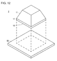
- Fig. 12 is a schematic side view for illustrating a film member stacking device 2 of a present embodiment 2.
- a film member stacking device 2 is used for stacking and affixing a gasket onto an MEA which is used for a fuel cell.
- the gasket is a first film member 100 and is a thin film-like member having an opening therein.
- the function of the gasket is to prevent gas, which passes through a catalyst layer, from leaking into the surroundings.
- the MEA is a second film member 200.
- the film member stacking device 2 has a plate 50 for holding the second film member 200 (not shown in Fig. 12 ), and a block 11 which is placed on the second film member held by the plate 50 and performs positioning of a first film member 100 and correction of the shape of the first film member.
- the plate 50 is a flat plate-like member.
- a material which transmits at least light required for the positioning to be described later is used.
- hard and light transparent members such as acrylic resin or polycarbonate are preferably used.
- the plate 50 preferably holds the second film member 200 through vacuum suction or electrostatic suction. This is used in order to prevent the position of the positioned second film member 200 from moving during the stacking work since the second film member 200 is also thin and light. If the second film member 200 is to be positioned only by being allowed to still stand, such a holding device is not required.
- the block 11 is the same as the block 11 described in the embodiment 1. That is, the block has a shape in which the top of a quadrangular pyramid shape is cut off. A vertical portion 17 having a certain height is provided on a bottom surface portion 16. The vertical portion 17 becomes an outer end of the block. The vertical portion 17 contacts with an inner end of the opening of the first film member 100 when positioning the first film member 100.
- the material of the block 11 be, for example, a hard plastic such as acrylic resin or polycarbonate; or a ceramic.
- the block 11 is directly placed on the second film member 200.
- the material of the first block may be metal if the contact between the second film member 200 and metal does not cause any problem.
- Fig. 13 is a view for illustrating a stacking method of the present embodiment 2.
- the first film member 100 is a gasket and the second film member 200 is an MEA also in the embodiment 2.
- an adhesive is applied to both surfaces of the gasket, which is the first film member 100, in advance, and release paper is affixed thereon.
- the second film member 200 is placed on the plate 50.
- any position of the second film member 200 with respect to the plate 50 may be taken on the second plate 50 as long as the position is within a range in which an end portion (in particular, a corner) of the catalyst layer is recognized using a camera to be described later.
- the block 11 is placed at a predetermined position of the second film member 200, which is the catalyst layer herein.
- the second film member 200 which is the catalyst layer herein.
- the MEA which is the second film member 200 is a film member in which a catalyst layer (second member) 202 is formed on an electrolyte membrane (first member) 201.
- Light transmittance in the electrolyte membrane 201 and the catalyst layer 202 for this is different from each other.
- the portion of the catalyst layer 202 has low light transmittance compared to the portion configured of only the electrolyte membrane 201 (that is, the periphery portion on which the catalyst layer is not formed). Therefore, when the plate 50 is exposed to light from the bottom of the plate and the transmitted light is photographed using a camera from the top of the plate, a portion with the catalyst layer in the photographed image is dark and the other portion is bright. Accordingly, the end portion of the catalyst layer 202 can be detected.
- An already existing position detecting system may be used for such a position detecting system.
- a light source is disposed under the plate 50 and a camera is disposed on the top (a side on which the block 11 is placed) of the plate.
- the block may be positioned by putting the image of the camera into a personal computer or the like and detecting the position of the catalyst layer, that is, the range of the dark portion in the image using image recognition software which is introduced in the personal computer in advance.
- Positioning of the block 11 is performed so as to align an outer end of a bottom surface portion of the block at a position which is separated from the detected end portion of the catalyst layer by a predetermined amount.
- the position separated from the end portion of the catalyst layer by a predetermined amount refers to an amount for separating the outer end of the block from the end portion of the catalyst layer which is detected by an amount corresponding to a different size when the size of the bottom surface portion of the block is larger than that of the catalyst layer.
- the size of the bottom surface portion of the block is the same as or slightly greater than that of the catalyst layer. This is required in order to prevent the gasket from being hung over the catalyst layer as also described in the embodiment 1.
- the positioning of the block 11 may also be visually performed without using such a position detecting system.
- the first film member 100 is pressed to and affixed on the second film member 200 such that the block 11 is passed through the opening of the first film member 100.
- the release paper is removed.
- a squeegee or the like may be used similarly to the embodiment 1 (refer to Fig. 9 ).
- a stacked body configured to have the first film member 100 and the second file member 200 is formed by removing the block 11.
- the first film member 100 may be pressed down so as to prevent the first film member from being peeled off from the second film member 200 along with the block 11.
- the squeegee or the like which is used when the first film member 100 is passed through the block 11, as it is, as a tool for pressing the first film member 100.
- the squeegee 300 is moved using the guide plate 350, since the guide plate 350 and the squeegee 300 are configured separately from the block 11, it is possible to remove the block 11 while pressing the first film member 100 using the squeegee 300.
- the first film member 100 may be pressed using other members (tools) instead of the squeegee.
- the first film member 100 may be prevented from being adhered to the block 11 when removing the block 11, by removing the block 11 after the first film member 100 is sufficiently compressed and adhered onto the second film member 200.
- pressure may be applied to the first film member 100 and the second film member 200 for making the first film member and the second film member be closely adhered to each other.
- the same operation may be performed after turning over the second film member 200 thereafter.
- Fig. 14 is a view for illustrating actions of embodiments.
- a thin film member such as a gasket having an opening therein is, for example, easily curled as a whole as shown in Fig. 14(a) , or a wrinkle 150 is easily formed in a portion of the film member as shown in Fig. 14(b) . For this reason, in some cases, the shape of the opening is not settled even if the film member is simply positioned at the outer end portion of the film member.
- gasket and the MEA which are examples of the first and second film members will be described in detail.
- the gasket is the first film member 100 in the present embodiment.
- the gasket include rubber materials such as fluorine rubber, silicone rubber, ethylene propylene rubber (EPDM), and polyisobutylene rubber; fluorine-based polymeric materials such as polytetrafluoroethylene (PTFE), polyvinylidene fluoride (PVDF), polyhexafluoropropylene, tetrafluoroethylene-hexafluoropropylene copolymers (FEP); and thermoplastic resins such as polyolefin and polyester.
- PTFE polytetrafluoroethylene
- PVDF polyvinylidene fluoride
- FEP tetrafluoroethylene-hexafluoropropylene copolymers
- thermoplastic resins such as polyolefin and polyester.
- the thickness of the gasket is preferably 50 ⁇ m to 2 mm and more preferably about 100 ⁇ m to 1 mm.
- the catalyst layer is a layer in which a reaction actually proceeds. Specifically, an oxidation reaction of hydrogen proceeds in an anode-side catalyst layer and a reduction reaction of oxygen proceeds in a cathode-side catalyst layer.
- the catalyst layer includes a catalyst component, a conductive carrier which carries the catalyst component, and a proton conductive polyelectrolyte.
- a well-known catalyst can be used without any particular limitation as long as the catalyst component has a catalyst action on the oxidation reaction of the hydrogen.
- a well-known catalyst can be used without any particular limitation as long as the catalyst component has a catalyst action on the reduction reaction of the oxygen.
- the catalyst component is selected from metals such as platinum, ruthenium, iridium, rhodium, palladium, osmium, tungsten, lead, iron, chromium, cobalt, nickel, manganese, vanadium, molybdenum, gallium, and aluminum; and alloys thereof.
- a catalyst component at least containing platinum is preferably used in order to improve a catalytic activity, poisoning resistance with respect to carbon monoxide, heat resistance, and the like.
- the composition of the alloy depends on the type of metal to be alloyed, but may be set to 30 at.% to 90 at.% of platinum and 10 at.% to 70 at.% of metal to be alloyed.
- the composition of the alloy when using the alloy as a cathode-side catalyst varies depending on the type of metal to be alloyed, and can be appropriately selected by those skilled in the art.
- the composition thereof is preferably set to 30 art.% to 90 at. % of platinum and 10 at.
- the alloy is a collective term for a material in which one or more kinds of metallic elements or non-metallic elements are generally added to a metallic element, and which has metallic properties.
- As the structure of the alloy there is an eutectic alloy as a mixture of which component elements are formed of separate crystals, a structure of which component elements are completely dissolved together and become a solid solution, a structure of which component elements form an intermetallic compound or a compound of metal and non-metal, or the like, and any structure may be used in the present application.
- the catalyst component used in the anode catalyst layer and the catalyst component used in the cathode catalyst layer can be appropriately selected from the above.
- the same definition is provided to describe both of the catalyst component used in the anode catalyst layer and the catalyst component used in the cathode catalyst layer, which are collectively called “catalyst component” unless otherwise specified.
- the catalyst component of the anode catalyst layer and the catalyst component of the cathode catalyst layer be the same as each other, and both the catalyst components can be appropriately selected so as to exhibit the above-described desired action.
- the same shape or the same size as that of the well-known catalyst component can be used without any particular restriction.
- the catalyst component it is preferable that the catalyst component have a granular shape.
- the average particle size of catalyst particles is preferably 1 nm to 30 nm, more preferably 1.5 nm to 20 nm, still more preferably 2 nm to 10 nm, and particularly preferably 2 nm to 5 nm. If the average particle size of the catalyst particles is a value within such a range, the balance, which relates to an effective electrode area in which an electrochemical reaction proceeds, between catalyst utilization efficiency and simplicity of carriage can be appropriately controlled.
- the "average particle size of the catalyst particles" in the present invention can be measured as an average value of crystallite diameters which are obtained by half-value width of a diffraction peak of catalyst components in X-ray diffraction or as an average value of particle sizes of catalyst components examined using a transmission type electron microscopic image.
- the conductive carrier functions as a carrier for carrying the above-described catalyst component and as an electron conducting path which is involved in giving and receiving electrons between itself and the catalyst component.
- any conductive carrier may be used as long as the conductive carrier has a specific surface area for carrying a catalyst component in a desired dispersion state and has sufficient electron conductivity, and a carbon-based material of which the main component is carbon is preferable.
- Specific examples thereof include carbon particles formed of carbon black, graphitized carbon black, activated carbon, coke, natural graphite, artificial graphite, carbon nanotubes, carbon nanohorns, and carbon fibril structures.
- the main component is carbon refers to a carbon atom being included therein as a main component, and is a concept including both of comprising of only the carbon atom and substantially comprising of the carbon atom. Elements other than the carbon atom may be included therein in order to improve characteristics of the fuel cell depending on the circumstances.
- substantially comprising of the carbon atom means that contamination of impurities less than or equal to about 2 mass% to 3 mass% can be allowed.
- a graphitized conductive material or more preferably a graphitized carbon material such as graphitized carbon black in a catalyst layer, in particular, in an anode-side catalyst layer, as a conductive carrier can improve corrosion resistance of the conductive material, which is preferable.
- the graphitized conductive material has a small covering area of an ion conductive material and has a small evaporation area of liquid water, and therefore, there is a concern that the conductive material may be frozen at a temperature below zero or may flood at room temperature. It is possible to improve drainage characteristics by setting a hydrophilic porous layer so as to make the hydrophilic porous layer adjacent to the catalyst layer using the graphitized conductive material.
- a membrane electrode assembly to be described later is provided in which both starting property at a temperature below zero and high-current density operation at room temperature are achieved and to which corrosion resistance of the conductive material is imparted.
- the graphitized carbon black have a spherical shape; the average lattice surface spacing d 002 of a [002] surface which is calculated from X-ray diffraction be 0.343 nm to 0.358 nm; and the BET specific surface area be 100 m 2 /g to 300 m 2 /g.
- the BET nitrogen specific surface area of the conductive carrier may be a specific surface area which is sufficient for highly dispersing and carrying the catalyst component, and is preferably 20 m 2 /g to 1600 m 2 /g and more preferably 80 m 2 /g to 1200 m 2 /g. If the specific surface area of the conductive carrier is a value within such a range, the balance between dispersibility of the catalyst component on the conductive carrier and effective utilization ratio of the catalyst component can be appropriately controlled.
- the size of the conductive carrier is not also particularly limited, but the average particle size may be 5 nm to 200 nm and preferably about 10 nm to 100 nm in view of the simplicity of carriage, the catalyst utilization efficiency, and controlling the thickness of the electrode catalyst layer to be within an appropriate range.
- the carried amount of the catalyst component with respect to the total amount of the electrode catalyst is preferably 10 mass% to 80 mass% and more preferably 30 mass% to 70 mass%. If the carried amount of the catalyst component is a value within such a range, the balance between the dispersibility of the catalyst component on the conductive carrier and the catalyst performance can be appropriately controlled.
- the carried amount of the catalyst component can be measured through inductively coupled plasma emission spectroscopy (ICP).
- a carrier it is possible to perform the carriage of the catalyst component by a carrier through a well-known method.
- well-known methods such as an impregnation method, a liquid-phase reduction carrying method, an evaporation to dryness method, a colloid adsorption method, a spray pyrolysis method, and a reversed micelle (microemulsion method).
- a commercial product may be used as the electrode catalyst.
- Examples of such a commercial product include electrode catalysts manufactured by, for example, Tanaka Kikinzoku Kogyo K.K., N.E. CHEMCAT CORPORATION, E-TEK Inc., Johnson Matthey, and the like. These electrode catalysts are catalysts in which platinum or a platinum alloy is carried by a carbon carrier (20 mass% to 70 mass% of the carried concentration of catalyst species).
- examples of the carbon carrier include Ketjen black, Vulcan, acetylene black, black pearl, graphitized carbon carrier (for example, graphitized Ketjen black) which is subjected to a heat treatment in advance at a high temperature, carbon nanotubes, carbon nanohorns, carbon fiber, and mesoporous carbon.
- the BET nitrogen specific surface area of the electrode catalyst be greater than the BET specific surface area of the conductive material contained in the hydrophilic porous layer.
- the thickness of the catalyst layer be thicker than the adjacent hydrophilic porous layer.
- the catalyst layer contains an ion conductive polyelectrolyte in addition to the electrode catalyst.
- the polyelectrolyte is not particularly limited, and well-known knowledge in the related art can be appropriately referred to.
- an ion exchange resin constituting the above-described polyelectrolyte membrane can be added to the catalyst layer as the polyelectrolyte.
- the catalyst layer is the hydrophilic porous layer, the above-described polyelectrolyte is used as the ion conductive material.
- the thickness of the catalyst layer is not particularly limited as long as it is possible to exhibit the catalyst action of the oxidation reaction (anode-side) of hydrogen and the reduction reaction (cathode-side) of oxygen, and the same thickness as that in the related art can be used.
- the thickness of each catalyst layer is preferably 1 ⁇ m to 10 ⁇ m.
- the method of coating the top of a base material with catalyst ink is not particularly limited, and similarly, well-known methods such as a screen printing method, a sedimentation method, and a spray method can be used.
- the base material well-known sheets such as a polytetrafluoroethylene (PTFE) sheet, polyester sheets like a polyethylene-terephthalate (PET) sheet, and the like, can be used.
- PTFE polytetrafluoroethylene
- PET polyethylene-terephthalate
- the base material can be appropriately selected depending on the type of catalyst ink (particularly, conductive carrier such as carbon in the ink) to be used.
- the catalyst layer formed on the base material is transferred onto an electrolyte membrane and becomes an MEA.
- the MEA is the second film member 200 in the present embodiments.
- the electrolyte membrane is formed of an ion exchange resin and has a function of selectively transmitting a proton, which is generated in an anode-side catalyst layer while operating PEFC, to a cathode-side catalyst layer along a thickness direction.
- the electrolyte membrane has a function as a partition for preventing fuel gas, which is supplied to the anode side, and oxidant gas, which is supplied to the cathode-side, from being mixed together.
- the specific configuration of the electrolyte membrane is not particularly limited and a well-known electrolyte membrane in the related art in the field of the fuel cell can be appropriately employed.
- the electrolyte membrane is broadly classified into a fluorine-based polyelectrolyte membrane and a hydrocarbon-based polyelectrolyte membrane depending on the type of the ion exchange resin which is a constituent material.
- Examples of the ion exchange resin constituting the fluorine-based polyelectrolyte membranes include perfluorocarbon sulfonic acid-based polymers such as Nafion (registered trademark, manufactured by DuPont), Aciplex (registered trademark, manufactured by Asahi Kasei Corporation), Flemion (registered trademark, manufactured by Asahi Glass Co., Ltd.); a perfluorocarbon phosphonic acid-based polymer; a trifluoro styrene sulfonic acid-based polymer; an ethylene tetrafluoroethylene-g-styrene sulfonic acid-based polymer, an ethylene-tetrafluoroethylene copolymer, and polyvinylidene fluoride-perfluorocarbon sulfonic acid-based polymer.
- perfluorocarbon sulfonic acid-based polymers such as Nafion (registered trademark, manufactured by DuPont), Aciplex (
- fluorine-based polyelectrolyte membranes are preferably used in view of power generation performance such as heat resistance and chemical stability, andfluorine-based polyelectrolyte membranes constituted of the perfluorocarbon sulfonic acid-based polymer are particularly preferably used.
- hydrocarbon-based electrolyte examples include sulfonated polyether sulfone (S-PES), sulfonated polyaryl ether ketone, sulfonated polybenzimidazole alkyl, phosphonated polybenzimidazole alkyl, sulfonated polystyrene, sulfonated polyether ether ketone (S-PEEK), and sulfonated polyphenylene (S-PPP).
- S-PES sulfonated polyether sulfone
- S-PEEK sulfonated polyether ether ketone
- S-PPP sulfonated polyphenylene
- These hydrocarbon-based polyelectrolyte membranes are preferably used in view of the manufacturing such as inexpensive raw materials, simple manufacturing process, and high selectivity of materials.
- the above-described ion exchange resin may be used singly or in combination of two or more thereof.
- the thickness of the electrolyte membrane may be appropriately determined in consideration of the characteristics of the obtained MEA or PEFC and there is no particular restriction.
- the thickness of the polyelectrolyte membrane is preferably 5 ⁇ m to 300 ⁇ m, more preferably 10 ⁇ m to 200 ⁇ m, and still more preferably 15 ⁇ m to 150 ⁇ m. If the thickness thereof is a value within such a range, the balance between strength while manufacturing a membrane or durability during use, and the output characteristics during use can be appropriately controlled.
- the sizes between the outer end of the catalyst layer and the inner end of the opening of the gasket are described to be the same as each other or to slightly have a space therebetween.
- the present invention is not limited thereto and the gasket may be set to be hung over the catalyst layer. In this case, it is not preferable to have a portion in which the gasket is hung over and a portion in which the gasket is not hung over the catalyst layer.
- the gasket is set to be partially hung over all of the sides of the catalyst layer.
- the gasket is affixed on both surfaces of the MEA, it is preferable to set the gasket so as to certainly hang over the four sides of the catalyst layer at an identical position on both the surfaces.
- the first film member 100 is not limited to the gasket, and the present invention is applicable to any film-like member having an opening.
- the present invention is also applicable to an O-ring (for example, the shape as shown in Fig. 3 ) or the like.
Landscapes
- Engineering & Computer Science (AREA)
- Life Sciences & Earth Sciences (AREA)
- Manufacturing & Machinery (AREA)
- Sustainable Development (AREA)
- Sustainable Energy (AREA)
- Chemical & Material Sciences (AREA)
- Chemical Kinetics & Catalysis (AREA)
- Electrochemistry (AREA)
- General Chemical & Material Sciences (AREA)
- Mechanical Engineering (AREA)
- Fuel Cell (AREA)
- Laminated Bodies (AREA)
Abstract
Description
- The present invention relates to a film member stacking device and a method of the same.
- In recent years, a fuel cell, which operates even at room temperature and can have high power density, has been attracting attention as a power source for electric vehicles and as a stationary power source in response to social needs or trends based on energy or environmental problems. In principle, a product of a fuel cell due to an electrode reaction is water and the fuel cell is a clean power generation system having little impact on the global environment. Particularly, a polymer electrolyte fuel cell (PEFC) operates at a comparatively low temperature, and therefore, is anticipated as a power source for an electric vehicle.
- Such a fuel cell includes a membrane electrode assembly (hereinafter, referred to as MEA) having an electrolyte membrane; a catalyst layer which is formed on both surfaces of the membrane; a gas diffusion layer (GDL); and the like. Moreover, the fuel cell is structured such that a plurality of MEAs are stacked through a separator.
- The MEAs and the separators are alternately stacked and are further stacked together with a current collector plate that collects generated power; an insulating plate that insulates an end plate and the current collector plate; and the like.
- A hole, through which fuel gas having hydrogen, air as oxidant gas, or the like is passed, is provided in each of these members. An O-ring, a gasket, or the like is disposed between each of the members to prevent leakage of these fluids.
- In the related art, when manufacturing such a fuel cell, in order to position each of the members at each predetermined position, each side surface of the members are set to be brought into contact with a positioning guide (PTL 1).
- [PTL 1] Publication of Japanese Patent Application
2003-86232 - However, in the method disclosed in
PTL 1, even though it is possible to position the MEAs, the separators, the current collector plates, the end plates, the insulating plates, and the like, it is not possible to position the O-rings, the gaskets and the like therebetween. - This happens because the O-ring or the gasket is deformed, even if the side surface (outer end) of the O-ring, the gasket, or the like is abutted to the guide since the O-ring, the gasket, or the like is thin and has low rigidity.
- An object of the present invention is to provide a film member stacking device and a method of the same, which are capable of correcting deformation of a film member.
- In order to achieve the above-described object, the film member stacking device of the present invention includes a block provided with an outer end that contacts with an inner end of an opening of a first film member which has the opening, in which the inner end of the opening of the first film member is positioned by the block and the first film member is stacked on a second film member.
- In addition, in order to achieve the above-described object, a method of stacking a film member of the present invention includes a step of positioning a first film member so that an inner end of an opening of the first film member contacts with an outer end of a block which is provided with the outer end that contacts with the inner end of the opening of the first film member which has the opening; and a step of stacking the first film member positioned by the block on the second film member.
- According to the present invention, the block is allowed to pass through the opening of the first film member so that the inner end of the opening of the first film member contacts with the outer end of the block. Accordingly, even if the first film member is deformed, it is possible to return the shape of the opening to its original shape by correcting the deformation and stack the first film member on the second film member.
-
-
Fig. 1 is a schematic perspective view for illustrating a film member stacking device of apresent embodiment 1. -
Fig. 2 is a view for illustrating an example of a shape of an opening of a first film member and a shape of a block. -
Fig. 3 is a view for illustrating an example of a shape of an opening of another first film member and a shape of a block. -
Fig. 4 is a view for illustrating an example of a shape of an opening of still another first film member and a shape of a block. -
Fig. 5 is a plan view of a first plate. -
Fig. 6 is a plan view of a second plate. -
Fig. 7 is a view for illustrating a positional relationship of a second film member on the second plate. -
Fig. 8 is a side view for illustrating positional relationships between the first plate, the block, the second plate, and the second film member. -
Fig. 9 is a view for illustrating a stacking method of thepresent embodiment 1. -
Fig. 10 is a view for illustrating the stacking method of thepresent embodiment 1. -
Fig. 11 is a view for illustrating the stacking method of thepresent embodiment 1. -
Fig. 12 is a schematic side view for illustrating a film member stacking device of apresent embodiment 2. -
Fig. 13 is a view for illustrating a stacking method of thepresent embodiment 2. -
Fig. 14 is a view for illustrating actions of embodiments. - Hereinafter, embodiments of the present invention will be described with respect to accompanying drawings. The same elements in the description of the drawings are given the same reference numerals and the description thereof will not be repeated. In addition, the dimension ratio of the drawings is exaggerated for convenience of explanation, and in some cases, the dimension ratio is different from that of the actual ratio.
-
Fig. 1 is a schematic perspective view for illustrating a film member stacking device of the present embodiment. - A film
member stacking device 1 is used for stacking and affixing a gasket onto an MEA which is used for a fuel cell. Here, the gasket is a first film member and is a thin film-like member having an opening therein. The function of the gasket is to prevent gas, which passes through a catalyst layer, from leaking into the surroundings. The MEA is a second film member. - The film
member stacking device 1 is formed of two portions. One of them is formed of ablock 11 that is adapted to the shape of the opening inside the first film member and afirst plate 12 which holds the first film member and onto which ablock 11 is placed. Another one is formed of asecond plate 20 for holding the second film member. The broken line in the drawing indicates a position at which theblock 11 is placed on thefirst plate 12. - In addition, the film
member stacking device 1 has afilm guide 31 for positioning the second film member on thesecond plate 20; and aplate guide 32 for positioning thefirst plate 12 and thesecond plate 20, as accessories. Thefilm guide 31 and theplate guide 32 are freely removable from thesecond plate 20. Thefilm guide 31 and theplate guide 32 serve as a plate position adjusting means. The positioning method using thefilm guide 31 and theplate guide 32 will be described in a method of stacking the film member to be described later. In addition, theplate guide 32 may be provided on at least two adjacent sides of four sides of the second plate. Thefilm guide 31 and theplate guide 32 may be provided so as to come into contact with all of the sides thereof. However, if the film guide and the plate guide are provided on all of the sides thereof, when setting the second film member on thesecond plate 20, the second film member needs to be put into thefilm guides 31 which are provided on the four sides thereof, which can be problematic. In contrast, if the film guide and the plate guide are provided so as to come into contact with two sides thereof, it is possible to perform the positioning without any problem. In addition, it is easy, since the second film member only have to be abutted against two sides thereof, when setting the second film member on thesecond plate 20. - The
block 11 has a shape in which the top of a quadrangular pyramid shape is cut off. Anupper surface portion 15 and abottom surface portion 16 are quadrangles. The area of theupper surface portion 15 is smaller than that of thebottom surface portion 16. That is, the block is made to have the same outline from thebottom surface portion 16 to theupper surface portion 15 in a plan view viewed from an upper surface side or a bottom surface side, and the size thereof is made to decrease in a direction from thebottom surface portion 16 to theupper surface portion 15. - A
vertical portion 17 having a certain height is provided on thebottom surface portion 16. Thevertical portion 17 becomes an outer end of the block. Thevertical portion 17 contacts with an inner end of the opening of the first film member when positioning the first film member. - The height of the
vertical portion 17 may be higher than or equal to at least the thickness of the first film member (for example, the gasket). The height thereof is not particularly limited, but it is preferable to have a height to the extent that the inner end of the opening of the gasket easily contacts with thevertical portion 17 when theblock 11 is allowed to pass through the opening of the gasket. The thickness of the gasket is, for example, about 50 µm to 2 mm. Therefore, if thevertical portion 17 is made to have the same height in accordance with the thickness of the gasket, it becomes difficult to determine whether or not the inner end of the opening is reliably in contact with thevertical portion 17. Therefore, it is preferable that, when theblock 11 is allowed to pass through the gasket, thevertical portion 17 has a height to the extent that the vertical surface of thevertical portion 17 can be seen and the situation where the inner end of the opening of the gasket is in reliable contact with thevertical portion 17 can be seen. For example, it is sufficient if the height of the vertical portion is about 1 mm to 10 mm. - In addition, the size of the bottom surface portion of the block is formed to be the same as or slightly greater than that of the opening of the first film member. Accordingly, when performing positioning by allowing the
block 11 to pass through the opening of the first film member, it is possible to correct the shape of the first film member, in particular, the shape of the opening of the first film member to a shape having neither wrinkles nor distortion as the first film member is pulled. - The extent to which the size of the
bottom surface portion 16 of the block is increased over that of the opening of the first film member cannot be flatly determined in accordance with the size of the entire first film member, the size of the opening thereof, or the material of the first film member. For this reason, the block may have a size to the extent that the wrinkles or the distortion of the first film member can be corrected. When theblock 11 is excessively larger than the opening thereof, even if the shape of the first film member is corrected after allowing theblock 11 through the opening thereof, the shape of the opening of the first film member is changed since the opening of the first film member tends to return to its original shape in a step in which theblock 11 is removed. For this reason, there is a concern that the positioning accuracy may deteriorate. For example, in the case of the gasket, when the size of the shape which is formed by the inner end of the opening of the first film member as a space between opposite sides of the bottom surface portion of the block is regarded to be 100%, the shape formed by the outer end of the bottom surface portion of the block may be made larger to about 100.1% to 101%. With such a size, in view of the material (to be described later in detail) of the gasket, even if theblock 11 is allowed to pass through the opening, it is possible to reliably correct the shape of the gasket without causing any deformation due to theblock 11. - The height (vertical height from the bottom surface portion to a front surface portion) of the
block 11 is not limited at all. Theblock 11 may have a height which facilitates handling when stacking a film using theblock 11. - The
block 11 may have any material as long as the material is not easily deformed. For example, it is possible to use various materials such as metals such as aluminum alloy, stainless steel, and brass; a hard plastic such as acrylic resin or polycarbonate; or a ceramic. - In addition, the
block 11 may have a cavity therein as long as the external shape, in particular, the shape of thevertical portion 17, is maintained. - The
block 11 is made to have a shape which is adapted to the shape of the opening of the first film member.Figs. 2 to 4 are views for illustrating examples of the shapes of openings of the first film member and the shapes of blocks. InFigs. 2 to 4 , each (a) is a side view of theblock 11, each (b) is a plan view of thebottom surface portion 16 of the block, and each (c) is a plan view of afirst film member 100. - For example, when the shape of the
opening 101 of thefirst film member 100 is a quadrangle as shown inFig. 2(c) , the shape of thebottom surface portion 16 of the block also becomes a quadrangular shape in accordance with the shape of the opening thereof as shown inFigs. 2(a) and 2(b) . This example corresponds to theblock 11 shown inFig. 1 . The shape of the block shown herein is a square, but the same is true on a rectangle or the like. The size of thebottom surface portion 16 of the block is formed to be the same as or slightly greater than that of theopening 101 of thefirst film member 100. In the drawing, the size of the bottom surface portion of the block and the size of the opening of the first film member are drawn to be the same as each other (the same principle applies to other drawings). - In addition, for example, when the shape of the
opening 101 of thefirst film member 100 is a circle as shown inFig. 3(c) , the shape of thebottom surface portion 16 of the block also becomes a circular shape in accordance with the shape of the opening thereof, as shown inFigs. 3(a) and 3(b) . Even in this case, similarly toFig. 1 , the block is similarly scaled down from thebottom surface portion 16 to theupper surface portion 15. Accordingly, the shape of theupper surface portion 15 also becomes a circular shape. - In addition, for example, when the shape of the
opening 101 of thefirst film member 100 is a quadrangular shape with arc-like corners, as shown inFig. 4 (c) , the shape of thebottom surface portion 16 of the block also becomes a quadrangular shape with arc-like corners in accordance with the shape of the opening thereof, as shown inFigs. 4 (a) and 4(b) . Even in this case, similarly toFig. 1 , the block is similarly scaled down from thebottom surface portion 16 to theupper surface portion 15. Accordingly, the shape of theupper surface portion 15 also becomes a quadrangular shape with arc-like corners. - In addition, the shape of the
block 11 may be determined in accordance with the various shapes of the gaskets. - Next, the
first plate 12 is provided such that theblock 11 is placed thereon, and holds the first film member which is positioned by theblock 11. -
Fig. 5 is a plan view of thefirst plate 12 and is a view when viewed from a side on which theblock 11 is placed. The broken line in the drawing indicates a position at which theblock 11 is placed. - As shown in the drawing, the
first plate 12 is a flat plate-like member. In thefirst plate 12, in order to hold the first film member, for example, vacuum suction or electrostatic suction is used. InFig. 5 , a case of vacuum suction is illustrated. As shown in the drawing, there is ahole 18 which is connected to a vacuum suction device (not shown), and agroove 19 which is in communication with thehole 18. Asingle hole 18 or asingle groove 19 may be provided. However, it is preferable that thegroove 19 be provided so as to continuously surround the periphery of the position at which theblock 11 is placed in order to reliably hold the first film member. - Besides this, although not shown in the drawing, a plurality of
grooves 19 may be provided with respect to ahole 18, or a plurality of suction holes connected to a vacuum suction device may be provided so as to surround the periphery of the position at which theblock 11 is placed, without providing the groove. - In addition, in order to more strongly perform the vacuum suction of the first film member, an O-ring (not shown) may be further provided in the outer periphery of the groove 19 (or a plurality of suction holes).
- In a case of using the electrostatic suction, although not shown in the drawing, an electrode for the electrostatic suction may be provided so as to surround the periphery of the position at which the
block 11 is placed. - With the
first plate 12 which holds the first film member positioned by theblock 11 in this manner, it is possible to maintain the corrected shape of the first film member, even after theblock 11 is removed (refer to a method of stacking the film member to be described later). - There are various techniques for positioning the
first plate 12 and theblock 11. For example, theblock 11 is positioned by providing a step in a portion of thefirst plate 12 on which theblock 11 is placed. Bolt holes are provided in thefirst plate 12 and theblock 11, and bolts, which pass through these bolt holes, are inserted therein in a state in which theblock 11 is placed on thefirst plate 12 to fix and position the block thereto. A concave portion is provided on thefirst plate 12 and a convex portion is provided under theblock 11 to position the block using the combination of the concave and convex portions. Besides, other techniques may be applied as long as thefirst plate 12 and theblock 11 are positioned at a predetermined position. As a matter of course, the positioning of theblock 11 with respect to thefirst plate 12 is performed to position theblock 11 on thefirst plate 12 such that the inner end of the opening of the first film member is positioned at a predetermined position of the second film member. - However, a projection or the like is not provided on the surface of the
first plate 12 on which the first film member is held. This is because the first film member held by thefirst plate 12 is superimposed on the second film member on thesecond plate 20 together with thefirst plate 12, as will be described later, and therefore, any projection on the surface of thefirst plate 12 on which the first film member is held interrupts the positioning therebetween. - It is preferable that the material of the
first plate 12 be a non-metallic material, for example, a hard plastic such as acrylic resin or polycarbonate; or a ceramic. This is required in order to prevent any metal from being introduced to the second film member since thefirst plate 12 contacts with the second film member when stacking the first film member on the second film member. As a matter of course, the material of the first plate may be metal if the contact between the second film member and metal does not cause any problem. - Next, the
second plate 20 is a plate for positioning the second film member.Fig. 6 is a plan view for illustrating thesecond plate 20. - As shown in the drawing, the
second plate 20 has a flat plate-like shape. It is preferable that the material of thesecond plate 20 be a hard plastic such as acrylic resin or polycarbonate; or a ceramic, for example. Thesecond plate 20 contacts with the second film member. Therefore, it is preferable that thesecond plate 20 be formed of a non-metallic material in a case in which the second film member (for example, an MEA) dislikes metal. As a matter of course, the material of the second plate may be metal if the contact between the second film member and metal does not cause any problem. - Although not shown in the drawing, the
second plate 20 may hold the second film member through vacuum suction or electrostatic suction. This is required in order to prevent the position of the positioned second film member from moving during the stacking work since the second film member is also thin and light. If the second film member is to be positioned only by being allowed to still stand, such a holding device is not required. - A method of stacking a film member using the above-described film
member stacking device 1 of thepresent embodiment 1 will be described. - First, the positional relationship between each member will be described.
Fig. 7 is a view illustrating a positional relationship of the second film member on the second plate. - Here, an example of an MEA as a
second film member 200 will be described. In the MEA, acatalyst layer 202 is formed on both surfaces of an electrolyte membrane 201 (in the drawing, only thecatalyst layer 202 on one surface of theelectrolyte membrane 201 is shown (the same applies to other drawings)). When stacking the first film member (here, gasket) on the MEA, it is desired that the gasket be stacked on the periphery of the catalyst layer without covering the catalyst layer. An MEA as thesecond film member 200 is a film member in which the catalyst layer (second member) 202 is formed on the electrolyte membrane (first member) 201. - A
film guide 31 is provided in order to position and dispose the second film member 200 (MEA) at a predetermined position on thesecond plate 20, as illustrated inFig. 7 . - At this time, it is possible to position the second film member in an X direction and a Y direction on a plane coordinate by setting the width (w in the drawing) of the
film guide 31 as a distance between each outer end of two adjacent sides of four sides of thesecond plate 20 and each outer end of the second film member 200 (MEA). Accordingly, thefilm guide 31 may be provided so as to have a predetermined distance from each outer end of the two adjacent sides of four sides of thesecond plate 20. In general, the distances thereof in the X direction and the Y direction may be the same as each other, and therefore, the widths (the width Wx in the X direction and the width Wy in the Y direction in the drawing) of thefilm guide 31 may be the same as each other. As a matter of course, if the second film member is to be located at a different position in the X direction and the Y direction, the width of thefilm guide 31 may be changed in accordance with the position. - In addition, the same principle applies to the
plate guide 32, and it is possible to position the plate in an X direction and a Y direction on a plane coordinate (refer toFig. 1 ) by providing a plate guide at each outer end of two adjacent sides of four sides of thesecond plate 20. - The
film guide 31 may not be provided, and the second film member 200 (MEA) may be positioned by making the second film member 200 (MEA) be directly abutted against theframe guide 32. -
Fig. 8 is a side view for illustrating positional relationships between the first plate, the block, the second plate, and the second film member. The drawing is provided only to illustrate the positional relationships therebetween and is not for illustrating a state while stacking the first film member and the second film member. In addition, thefilm guide 31 and theplate guide 32 are provided on two adjacent sides of thesecond plate 20 as previously described, but only a side of thesecond plate 20 is shown inFig. 8 to simplify understanding. - As illustrated in the drawing, the position of the
block 11 with respect to thefirst plate 12 is set such that the inner end of the opening of the first film member 100 (gasket) is coincident with the outer end of thecatalyst layer 202 or is positioned slightly outside the outer end thereof (in the drawing, the inner end of the opening thereof is coincident with the outer end of the catalyst layer) in a state in which each side portion of thefirst plate 12 and thesecond plate 20 is positioned so as to be flush with each other using theplate guide 32. That is, the outer end of theblock 11 is set to be coincident with or to be positioned slightly outside the outer end of thecatalyst layer 202 of the second film member 200 (MEA) on thesecond plate 20. - It is possible to stack the first film member 100 (gasket) on the periphery of the
catalyst layer 202 by simply positioning thefirst plate 12 and thesecond plate 20 using theplate guide 32, by positioning these members in this manner. - When the gasket is stacked on an MEA, it is preferable that there is no gap between the outer end of the catalyst layer and the inner end of the opening of the gasket. However, a slight gap therebetween will not be a problem. The function of the gasket is to prevent leakage of gas which is passed through the catalyst layer. For this reason, if the gasket is hung on the catalyst layer and covers a portion of the catalyst layer, the utilization efficiency of the catalyst layer deteriorates, which is not preferable. In contrast, there is no influence on the effect of preventing leakage of the gas, even if there is a gap between the outer end of the catalyst layer and the inner end of the opening of the gasket. Therefore, even a slight gap therebetween will not be a problem.
- The stacking method will be described.
Figs. 9 to 11 are views for illustrating the stacking method of thepresent embodiment 1. - First, the
block 11 is placed on thefirst plate 12. Then, thefirst film member 100 is compressed onto the surface of thefirst plate 12 such that theblock 11 is passed through the opening of thefirst film member 100 from the top of theblock 11. At this time, the opening is reliably put up to thebottom surface portion 16 of theblock 11, that is, the opening is reliably put thereto so as to be attached to the surface of thefirst plate 12. - This may be accomplished using a
squeegee 300 or the like as shown inFig. 9 (a) . Thesqueegee 300 uniformly compresses thefirst film member 100 in a direction of thebottom surface portion 16 of theblock 11 along the slope of theblock 11 from the top of theblock 11 such that the first film member is attached to the surface of the first plate 12 (that is, in the drawing, thesqueegee 300 is moved from the position of the alternate long and short dash line to the position of the solid line). Thesqueegee 300 may compress the first film member in a direction of thebottom surface portion 16 while maintaining the tension in a direction (arrow A shown in the drawing) of squeezing theblock 11, at all times. This may be accomplished, for example, by squeezing thesqueegee 300 by using foamed urethane or the like having excellent elasticity. - Alternately, as shown in
Figs. 9(b1) and 9(b2) , aguide plate 350 is provided separately, and thesqueegee 300 is configured to be moved along a groove 351 (or a rail) which is provided on theguide plate 350. The groove 351 (or the rail) on theguide plate 350 is provided such that abracket 352 moves along the inclination of the slope of theblock 11. Thesqueegee 300 is attached to thebracket 352 so as to be able to move along the slope of theblock 11 at all times. Accordingly, thesqueegee 300 compresses thefirst film member 100 in the direction of thebottom surface portion 16 of theblock 11 by being guided by the groove 351 (or the rail) from the top of theblock 11 such that the first film member is attached to the surface of the first plate 12 (that is, in the drawing, thesqueegee 300 is moved from the position of the alternate long and short dash line to the position of the solid line). -
Fig. 9(b1) is a view showing the guide plate when viewed from a side direction of the block andFig. 9(b2) is a view including the guide plate when viewed from a direction of the upper surface portion of the block (Fig. 9(b2) shows a state in which thefirst film member 100 is attached to the surface of the first plate 12). -
Figs. 9(a), 9(b1), and 9(b2) show views in which thesqueegee 300 is provided so as to come into contact with two facing sides (slopes) of theblock 11. However, the squeegee may be provided so as to come into contact with all of the four sides (slopes) of theblock 11. - An adhesive is applied to both surfaces or to a single surface of the gasket, which is the
first film member 100, used herein in advance. Release paper is spread on the surface of the adhesive surface in order to prevent the adhesive surface from being attached to other members while working. - Next, once the
first film member 100 is compressed up to thebottom surface portion 16 of theblock 11, thefirst plate 12 holds thefirst film member 100. Then, theblock 11 is removed. - Meanwhile, as shown in
Fig. 10 , theplate guide 32 is disposed on the outer periphery of thesecond plate 20 and thefilm guide 31 is provided on thesecond plate 20 along theplate guide 32. Then, thesecond film member 200 is positioned by thefilm guide 31 and is placed on thesecond plate 20. Thefilm guide 31 and theplate guide 32 are provided on two adjacent sides of thesecond plate 20 as previously described. However, only a side is shown inFig. 10 for easy understanding. - Next, as shown in
Fig. 11 , thefilm guide 31 is removed from thesecond plate 20. Then, the release paper of thefirst film member 100 on thefirst plate 12 is peeled off, and then, thefirst plate 12 is put on thesecond plate 20 along theplate guide 32 by making the surface of the first film member face thesecond plate 20. Accordingly, thefirst film member 100 is affixed onto thesecond film member 200. At this time, a pressure by which thefirst plate 12 is pressed in thesecond plate 20 direction may be applied such that thefirst film member 100 and thesecond film member 200 are closely adhered to each other. Theplate guide 32 is provided on two adjacent sides of thesecond plate 20 as previously described. However, only a side is shown inFig. 11 for easy understanding. - As described above, a stacked body configured to have the
first film member 100 and the second file member is formed. In a case of stacking thefirst film member 100 on both the surfaces of thesecond film member 200, the same operation may be performed after turning over thesecond film member 200 thereafter. - In the
present embodiment 1, the positioning of thefirst film member 100 on thefirst plate 12 and the positioning of thesecond film member 200 on thesecond plate 20 can be independently performed. - In addition, in the above-described stacking method, the
block 11 was set to be previously positioned on thefirst plate 100 in relation to thesecond film member 200 on thesecond plate 20. However, the present invention is not limited thereto and theblock 11 may be put on thefirst plate 100 regardless of the position of thesecond film member 200 on thesecond plate 20. In this case, after holding thefirst film member 100 using thefirst plate 100, the first film member may be positioned with respect to thesecond film member 200. In this case, thefilm guide 31 and theplate guide 32 are not required. -
Fig. 12 is a schematic side view for illustrating a filmmember stacking device 2 of apresent embodiment 2. - A film
member stacking device 2 is used for stacking and affixing a gasket onto an MEA which is used for a fuel cell. Here, the gasket is afirst film member 100 and is a thin film-like member having an opening therein. The function of the gasket is to prevent gas, which passes through a catalyst layer, from leaking into the surroundings. The MEA is asecond film member 200. - The film
member stacking device 2 has aplate 50 for holding the second film member 200 (not shown inFig. 12 ), and ablock 11 which is placed on the second film member held by theplate 50 and performs positioning of afirst film member 100 and correction of the shape of the first film member. - The
plate 50 is a flat plate-like member. Here, a material which transmits at least light required for the positioning to be described later is used. For example, hard and light transparent members such as acrylic resin or polycarbonate are preferably used. - The
plate 50 preferably holds thesecond film member 200 through vacuum suction or electrostatic suction. This is used in order to prevent the position of the positionedsecond film member 200 from moving during the stacking work since thesecond film member 200 is also thin and light. If thesecond film member 200 is to be positioned only by being allowed to still stand, such a holding device is not required. - The
block 11 is the same as theblock 11 described in theembodiment 1. That is, the block has a shape in which the top of a quadrangular pyramid shape is cut off. Avertical portion 17 having a certain height is provided on abottom surface portion 16. Thevertical portion 17 becomes an outer end of the block. Thevertical portion 17 contacts with an inner end of the opening of thefirst film member 100 when positioning thefirst film member 100. - However, it is preferable that the material of the
block 11 be, for example, a hard plastic such as acrylic resin or polycarbonate; or a ceramic. In thepresent embodiment 2, theblock 11 is directly placed on thesecond film member 200. For this reason, it is preferable to use non-metallic materials in case direct contact between thesecond film member 200 and metal is not preferable. As a matter of course, the material of the first block may be metal if the contact between thesecond film member 200 and metal does not cause any problem. - A method of stacking a film member using the above-described film
member stacking device 1 of thepresent embodiment 2 will be described. -
Fig. 13 is a view for illustrating a stacking method of thepresent embodiment 2. - Similarly to the
embodiment 1, thefirst film member 100 is a gasket and thesecond film member 200 is an MEA also in theembodiment 2. In addition, an adhesive is applied to both surfaces of the gasket, which is thefirst film member 100, in advance, and release paper is affixed thereon. - First, as shown in
Fig. 13(a) , thesecond film member 200 is placed on theplate 50. At this time, any position of thesecond film member 200 with respect to theplate 50 may be taken on thesecond plate 50 as long as the position is within a range in which an end portion (in particular, a corner) of the catalyst layer is recognized using a camera to be described later. - Next, as shown in
Fig. 13(b) , theblock 11 is placed at a predetermined position of thesecond film member 200, which is the catalyst layer herein. At this time, in order to check the position of the catalyst layer, it is possible to use, for example, a position detecting system using light. - The MEA which is the
second film member 200 is a film member in which a catalyst layer (second member) 202 is formed on an electrolyte membrane (first member) 201. Light transmittance in theelectrolyte membrane 201 and thecatalyst layer 202 for this is different from each other. Specifically, the portion of thecatalyst layer 202 has low light transmittance compared to the portion configured of only the electrolyte membrane 201 (that is, the periphery portion on which the catalyst layer is not formed). Therefore, when theplate 50 is exposed to light from the bottom of the plate and the transmitted light is photographed using a camera from the top of the plate, a portion with the catalyst layer in the photographed image is dark and the other portion is bright. Accordingly, the end portion of thecatalyst layer 202 can be detected. An already existing position detecting system may be used for such a position detecting system. For example, a light source is disposed under theplate 50 and a camera is disposed on the top (a side on which theblock 11 is placed) of the plate. Then, the block may be positioned by putting the image of the camera into a personal computer or the like and detecting the position of the catalyst layer, that is, the range of the dark portion in the image using image recognition software which is introduced in the personal computer in advance. - Positioning of the
block 11 is performed so as to align an outer end of a bottom surface portion of the block at a position which is separated from the detected end portion of the catalyst layer by a predetermined amount. Here, the position separated from the end portion of the catalyst layer by a predetermined amount refers to an amount for separating the outer end of the block from the end portion of the catalyst layer which is detected by an amount corresponding to a different size when the size of the bottom surface portion of the block is larger than that of the catalyst layer. The size of the bottom surface portion of the block is the same as or slightly greater than that of the catalyst layer. This is required in order to prevent the gasket from being hung over the catalyst layer as also described in theembodiment 1. - The positioning of the
block 11 may also be visually performed without using such a position detecting system. - Next, as shown in
Fig. 13(c) , thefirst film member 100 is pressed to and affixed on thesecond film member 200 such that theblock 11 is passed through the opening of thefirst film member 100. At this time, the release paper is removed. - For the operation of allowing the
block 11 to pass through the opening of thefirst film member 100, a squeegee or the like may be used similarly to the embodiment 1 (refer toFig. 9 ). - A stacked body configured to have the
first film member 100 and thesecond file member 200 is formed by removing theblock 11. When removing theblock 11, thefirst film member 100 may be pressed down so as to prevent the first film member from being peeled off from thesecond film member 200 along with theblock 11. For this operation, it is possible to use, for example, the squeegee or the like, which is used when thefirst film member 100 is passed through theblock 11, as it is, as a tool for pressing thefirst film member 100. Particularly, when thesqueegee 300 is moved using theguide plate 350, since theguide plate 350 and thesqueegee 300 are configured separately from theblock 11, it is possible to remove theblock 11 while pressing thefirst film member 100 using thesqueegee 300. - As a matter of course, the
first film member 100 may be pressed using other members (tools) instead of the squeegee. In addition, thefirst film member 100 may be prevented from being adhered to theblock 11 when removing theblock 11, by removing theblock 11 after thefirst film member 100 is sufficiently compressed and adhered onto thesecond film member 200. - In addition, after removing the
block 11, pressure may be applied to thefirst film member 100 and thesecond film member 200 for making the first film member and the second film member be closely adhered to each other. - In a case of stacking the
first film member 100 on both the surfaces of thesecond film member 200, the same operation may be performed after turning over thesecond film member 200 thereafter. - Actions which are common to the above-described
embodiments -
Fig. 14 is a view for illustrating actions of embodiments. - A thin film member such as a gasket having an opening therein is, for example, easily curled as a whole as shown in
Fig. 14(a) , or awrinkle 150 is easily formed in a portion of the film member as shown inFig. 14(b) . For this reason, in some cases, the shape of the opening is not settled even if the film member is simply positioned at the outer end portion of the film member. - In the
present embodiments second film member 200 as shown inFig. 14(c) by allowing theblock 11 to pass through the opening of thefirst film member 100. - In addition, as is previously described, it is possible to more reliably correct the shape of the opening of the
first film member 100 by making the size of theblock 11 be slightly larger than the size of the opening of thefirst film member 100. - In a case where there is a curl or a distortion in the film member, or the film member is wrinkled, manually spreading out the opening thereof to affix the opening onto a predetermined position requires a skill and does not go well if the operator is unskilled. From this point of view, it is possible to perform the positioning of the film member by automatically correcting such a shape of the opening using the
block 11 as shown in thepresent embodiments block 11 to pass through the opening. Therefore, the deformation such as the curl, the distortion, and the wrinkles can be solved by controlling only the inside of the opening. - Hereinafter, the gasket and the MEA (catalyst layer and electrolyte membrane) which are examples of the first and second film members will be described in detail.
- The gasket is the
first film member 100 in the present embodiment. Examples of the gasket include rubber materials such as fluorine rubber, silicone rubber, ethylene propylene rubber (EPDM), and polyisobutylene rubber; fluorine-based polymeric materials such as polytetrafluoroethylene (PTFE), polyvinylidene fluoride (PVDF), polyhexafluoropropylene, tetrafluoroethylene-hexafluoropropylene copolymers (FEP); and thermoplastic resins such as polyolefin and polyester. In addition, there is no particular restriction on the thickness of the gasket, but the thickness thereof is preferably 50 µm to 2 mm and more preferably about 100 µm to 1 mm. - The catalyst layer is a layer in which a reaction actually proceeds. Specifically, an oxidation reaction of hydrogen proceeds in an anode-side catalyst layer and a reduction reaction of oxygen proceeds in a cathode-side catalyst layer. The catalyst layer includes a catalyst component, a conductive carrier which carries the catalyst component, and a proton conductive polyelectrolyte.
- As the catalyst component used in the anode-side catalyst layer, a well-known catalyst can be used without any particular limitation as long as the catalyst component has a catalyst action on the oxidation reaction of the hydrogen. In addition, as the catalyst component used in the cathode-side catalyst layer, a well-known catalyst can be used without any particular limitation as long as the catalyst component has a catalyst action on the reduction reaction of the oxygen. Specifically, the catalyst component is selected from metals such as platinum, ruthenium, iridium, rhodium, palladium, osmium, tungsten, lead, iron, chromium, cobalt, nickel, manganese, vanadium, molybdenum, gallium, and aluminum; and alloys thereof. However, it is natural that other materials can be used. Among these, a catalyst component at least containing platinum is preferably used in order to improve a catalytic activity, poisoning resistance with respect to carbon monoxide, heat resistance, and the like. The composition of the alloy depends on the type of metal to be alloyed, but may be set to 30 at.% to 90 at.% of platinum and 10 at.% to 70 at.% of metal to be alloyed. The composition of the alloy when using the alloy as a cathode-side catalyst varies depending on the type of metal to be alloyed, and can be appropriately selected by those skilled in the art. The composition thereof is preferably set to 30 art.% to 90 at. % of platinum and 10 at. % to 70 at.% of other metals to be alloyed. The alloy is a collective term for a material in which one or more kinds of metallic elements or non-metallic elements are generally added to a metallic element, and which has metallic properties. As the structure of the alloy, there is an eutectic alloy as a mixture of which component elements are formed of separate crystals, a structure of which component elements are completely dissolved together and become a solid solution, a structure of which component elements form an intermetallic compound or a compound of metal and non-metal, or the like, and any structure may be used in the present application. At this time, the catalyst component used in the anode catalyst layer and the catalyst component used in the cathode catalyst layer can be appropriately selected from the above. In the description of the present specification, the same definition is provided to describe both of the catalyst component used in the anode catalyst layer and the catalyst component used in the cathode catalyst layer, which are collectively called "catalyst component" unless otherwise specified. However, it is unnecessary that the catalyst component of the anode catalyst layer and the catalyst component of the cathode catalyst layer be the same as each other, and both the catalyst components can be appropriately selected so as to exhibit the above-described desired action.
- As the shape or the size of the catalyst component, the same shape or the same size as that of the well-known catalyst component can be used without any particular restriction. However, it is preferable that the catalyst component have a granular shape. At this time, the average particle size of catalyst particles is preferably 1 nm to 30 nm, more preferably 1.5 nm to 20 nm, still more preferably 2 nm to 10 nm, and particularly preferably 2 nm to 5 nm. If the average particle size of the catalyst particles is a value within such a range, the balance, which relates to an effective electrode area in which an electrochemical reaction proceeds, between catalyst utilization efficiency and simplicity of carriage can be appropriately controlled. The "average particle size of the catalyst particles" in the present invention can be measured as an average value of crystallite diameters which are obtained by half-value width of a diffraction peak of catalyst components in X-ray diffraction or as an average value of particle sizes of catalyst components examined using a transmission type electron microscopic image.
- The conductive carrier functions as a carrier for carrying the above-described catalyst component and as an electron conducting path which is involved in giving and receiving electrons between itself and the catalyst component.
- Any conductive carrier may be used as long as the conductive carrier has a specific surface area for carrying a catalyst component in a desired dispersion state and has sufficient electron conductivity, and a carbon-based material of which the main component is carbon is preferable. Specific examples thereof include carbon particles formed of carbon black, graphitized carbon black, activated carbon, coke, natural graphite, artificial graphite, carbon nanotubes, carbon nanohorns, and carbon fibril structures. The expression that "the main component is carbon" refers to a carbon atom being included therein as a main component, and is a concept including both of comprising of only the carbon atom and substantially comprising of the carbon atom. Elements other than the carbon atom may be included therein in order to improve characteristics of the fuel cell depending on the circumstances. The expression that "substantially comprising of the carbon atom" means that contamination of impurities less than or equal to about 2 mass% to 3 mass% can be allowed.
- Use of a graphitized conductive material or more preferably a graphitized carbon material such as graphitized carbon black in a catalyst layer, in particular, in an anode-side catalyst layer, as a conductive carrier, can improve corrosion resistance of the conductive material, which is preferable. However, the graphitized conductive material has a small covering area of an ion conductive material and has a small evaporation area of liquid water, and therefore, there is a concern that the conductive material may be frozen at a temperature below zero or may flood at room temperature. It is possible to improve drainage characteristics by setting a hydrophilic porous layer so as to make the hydrophilic porous layer adjacent to the catalyst layer using the graphitized conductive material. Moreover, a membrane electrode assembly to be described later is provided in which both starting property at a temperature below zero and high-current density operation at room temperature are achieved and to which corrosion resistance of the conductive material is imparted. It is preferable that the graphitized carbon black have a spherical shape; the average lattice surface spacing d002 of a [002] surface which is calculated from X-ray diffraction be 0.343 nm to 0.358 nm; and the BET specific surface area be 100 m2/g to 300 m2/g.
- The BET nitrogen specific surface area of the conductive carrier may be a specific surface area which is sufficient for highly dispersing and carrying the catalyst component, and is preferably 20 m2/g to 1600 m2/g and more preferably 80 m2/g to 1200 m2/g. If the specific surface area of the conductive carrier is a value within such a range, the balance between dispersibility of the catalyst component on the conductive carrier and effective utilization ratio of the catalyst component can be appropriately controlled.
- The size of the conductive carrier is not also particularly limited, but the average particle size may be 5 nm to 200 nm and preferably about 10 nm to 100 nm in view of the simplicity of carriage, the catalyst utilization efficiency, and controlling the thickness of the electrode catalyst layer to be within an appropriate range.
- In the electrode catalyst, the carried amount of the catalyst component with respect to the total amount of the electrode catalyst is preferably 10 mass% to 80 mass% and more preferably 30 mass% to 70 mass%. If the carried amount of the catalyst component is a value within such a range, the balance between the dispersibility of the catalyst component on the conductive carrier and the catalyst performance can be appropriately controlled. The carried amount of the catalyst component can be measured through inductively coupled plasma emission spectroscopy (ICP).
- In addition, it is possible to perform the carriage of the catalyst component by a carrier through a well-known method. For example, it is possible to use well-known methods such as an impregnation method, a liquid-phase reduction carrying method, an evaporation to dryness method, a colloid adsorption method, a spray pyrolysis method, and a reversed micelle (microemulsion method).
- A commercial product may be used as the electrode catalyst. Examples of such a commercial product include electrode catalysts manufactured by, for example, Tanaka Kikinzoku Kogyo K.K., N.E. CHEMCAT CORPORATION, E-TEK Inc., Johnson Matthey, and the like. These electrode catalysts are catalysts in which platinum or a platinum alloy is carried by a carbon carrier (20 mass% to 70 mass% of the carried concentration of catalyst species). In the above description, examples of the carbon carrier include Ketjen black, Vulcan, acetylene black, black pearl, graphitized carbon carrier (for example, graphitized Ketjen black) which is subjected to a heat treatment in advance at a high temperature, carbon nanotubes, carbon nanohorns, carbon fiber, and mesoporous carbon.
- As described above, it is preferable that the BET nitrogen specific surface area of the electrode catalyst be greater than the BET specific surface area of the conductive material contained in the hydrophilic porous layer. In addition, as described above, it is preferable that the thickness of the catalyst layer be thicker than the adjacent hydrophilic porous layer.
- The catalyst layer contains an ion conductive polyelectrolyte in addition to the electrode catalyst. The polyelectrolyte is not particularly limited, and well-known knowledge in the related art can be appropriately referred to. For example, an ion exchange resin constituting the above-described polyelectrolyte membrane can be added to the catalyst layer as the polyelectrolyte. When the catalyst layer is the hydrophilic porous layer, the above-described polyelectrolyte is used as the ion conductive material.
- The thickness of the catalyst layer is not particularly limited as long as it is possible to exhibit the catalyst action of the oxidation reaction (anode-side) of hydrogen and the reduction reaction (cathode-side) of oxygen, and the same thickness as that in the related art can be used. Specifically, the thickness of each catalyst layer is preferably 1 µm to 10 µm. In addition, the method of coating the top of a base material with catalyst ink is not particularly limited, and similarly, well-known methods such as a screen printing method, a sedimentation method, and a spray method can be used.
- As the base material, well-known sheets such as a polytetrafluoroethylene (PTFE) sheet, polyester sheets like a polyethylene-terephthalate (PET) sheet, and the like, can be used. The base material can be appropriately selected depending on the type of catalyst ink (particularly, conductive carrier such as carbon in the ink) to be used.
- Moreover, the catalyst layer formed on the base material is transferred onto an electrolyte membrane and becomes an MEA. The MEA is the
second film member 200 in the present embodiments. - The electrolyte membrane is formed of an ion exchange resin and has a function of selectively transmitting a proton, which is generated in an anode-side catalyst layer while operating PEFC, to a cathode-side catalyst layer along a thickness direction. In addition, the electrolyte membrane has a function as a partition for preventing fuel gas, which is supplied to the anode side, and oxidant gas, which is supplied to the cathode-side, from being mixed together.
- The specific configuration of the electrolyte membrane is not particularly limited and a well-known electrolyte membrane in the related art in the field of the fuel cell can be appropriately employed. The electrolyte membrane is broadly classified into a fluorine-based polyelectrolyte membrane and a hydrocarbon-based polyelectrolyte membrane depending on the type of the ion exchange resin which is a constituent material. Examples of the ion exchange resin constituting the fluorine-based polyelectrolyte membranes include perfluorocarbon sulfonic acid-based polymers such as Nafion (registered trademark, manufactured by DuPont), Aciplex (registered trademark, manufactured by Asahi Kasei Corporation), Flemion (registered trademark, manufactured by Asahi Glass Co., Ltd.); a perfluorocarbon phosphonic acid-based polymer; a trifluoro styrene sulfonic acid-based polymer; an ethylene tetrafluoroethylene-g-styrene sulfonic acid-based polymer, an ethylene-tetrafluoroethylene copolymer, and polyvinylidene fluoride-perfluorocarbon sulfonic acid-based polymer. These fluorine-based polyelectrolyte membranes are preferably used in view of power generation performance such as heat resistance and chemical stability, andfluorine-based polyelectrolyte membranes constituted of the perfluorocarbon sulfonic acid-based polymer are particularly preferably used.
- Specific examples of the hydrocarbon-based electrolyte include sulfonated polyether sulfone (S-PES), sulfonated polyaryl ether ketone, sulfonated polybenzimidazole alkyl, phosphonated polybenzimidazole alkyl, sulfonated polystyrene, sulfonated polyether ether ketone (S-PEEK), and sulfonated polyphenylene (S-PPP). These hydrocarbon-based polyelectrolyte membranes are preferably used in view of the manufacturing such as inexpensive raw materials, simple manufacturing process, and high selectivity of materials. The above-described ion exchange resin may be used singly or in combination of two or more thereof. In addition, the ion exchange resin is not limited to the above-described materials and it is natural that other materials may also be used.
- The thickness of the electrolyte membrane may be appropriately determined in consideration of the characteristics of the obtained MEA or PEFC and there is no particular restriction. However, the thickness of the polyelectrolyte membrane is preferably 5 µm to 300 µm, more preferably 10 µm to 200 µm, and still more preferably 15 µm to 150 µm. If the thickness thereof is a value within such a range, the balance between strength while manufacturing a membrane or durability during use, and the output characteristics during use can be appropriately controlled.
- According to the above-described embodiment, the following effects are exhibited.
-
- (1) The
embodiments block 11 is passed through theopening 101 of thefirst film member 100 such that the inner end of the opening of thefirst film member 100 contacts with the outer end of theblock 11. Accordingly, even when thefirst film member 100 is deformed, it is possible to return the shape of theopening 101 to its original condition by correcting the deformation. Therefore, theopening 101 of thefirst film member 100 has its original shape when stacking the first film member on the second film member, and therefore, it is possible to position and stack the first film member as designed. - (2) Particularly in the
embodiment 1, thefirst film member 100 is held by thefirst plate 12 and thesecond film member 200 is held by thesecond plate 20. Therefore, it is possible to separately perform the correction of the shape of thefirst film member 100 and the positioning of the first film member with respect to thesecond film member 200. In addition, it is possible to separately prepare thefirst film member 100 and thesecond film member 200. - (3) In addition, in the
embodiment 1, the positioning of the opening of thefirst film member 100 and thesecond film member 200 is performed by positioning thefirst plate 12 and thesecond plate 20. Accordingly, it is possible to position and stack the opening of thefirst film member 100 at a predetermined position of thesecond film member 200 only by the positioning of the first and second plate. - (4) In addition, in the
embodiment 2, thesecond film member 200 is held by oneplate 50, theblock 11 is placed from the top of thesecond film member 200, and the opening of thefirst film member 100 is positioned to theblock 11. Accordingly, it is possible to correct the shape of thefirst filmmember 100 and to directly position the first film member to the second film member. In addition, thefirst film member 100 is positioned by placing theblock 11 on thesecond film member 200, and therefore, the process is simple. - (5) In addition, in the
embodiment 2, the end portion of the first member is detected by light using different light transmittance between the first member constituting thesecond film member 200 and the second member located thereon, and theblock 11 is placed at a position separated from the detected end portion by a predetermined amount. Accordingly, it is possible to position theblock 11 at a predetermined position of thesecond film member 200 using an optical system. - (6) In addition, commonly in the
embodiments first film member 100 is a rectangle or a square and theblock 11 has four sides that contact with each side of the rectangle or the square by corresponding to such a shape of the opening. Accordingly, it is possible to correct the shape of the opening of the rectangle or the square. - (7) In addition, commonly in the
embodiments block 11 is the same as or slightly larger than the size of the shape formed by the inner end of the opening of the first film member 100 (that is, the size of the shape formed by the outer end of theblock 11 is a size larger than or equal to the shape formed by the inner end of the opening of the first film member 100). Accordingly, it is possible to more reliably correct the shape of theopening 101 to its original shape by extending the deformed portion of thefirst film member 100 when positioning theopening 101 of thefirst film member 100 by allowing theblock 11 to pass through theopening 101 of thefirst film member 100. - (8) In addition, commonly in the
embodiments first film member 100 is a gasket used in a fuel cell, and thesecond film member 200 is a member which is used in the fuel cell and has a catalyst layer formed on a base material. The predetermined position on thesecond film member 200 is set to a position at which the inner end of the opening of the gasket is located on an outer side than the outer end of the catalyst layer. Accordingly, it is possible to stack the gasket so as to prevent the gasket from being hung over the catalyst layer. - Hereinbefore, the embodiments of the present invention have been described, but the present invention is not limited to the above-described embodiments and various modifications can be made.
- For example, in the above-described embodiments, when stacking the gasket on an MEA, the sizes between the outer end of the catalyst layer and the inner end of the opening of the gasket are described to be the same as each other or to slightly have a space therebetween. However, the present invention is not limited thereto and the gasket may be set to be hung over the catalyst layer. In this case, it is not preferable to have a portion in which the gasket is hung over and a portion in which the gasket is not hung over the catalyst layer. The gasket is set to be partially hung over all of the sides of the catalyst layer. Particularly, when the gasket is affixed on both surfaces of the MEA, it is preferable to set the gasket so as to certainly hang over the four sides of the catalyst layer at an identical position on both the surfaces.
- In addition, the
first film member 100 is not limited to the gasket, and the present invention is applicable to any film-like member having an opening. In addition, the present invention is also applicable to an O-ring (for example, the shape as shown inFig. 3 ) or the like. - In addition, needless to say, the present invention can have various modification modes which are determined by matters defined by the claims.
- Furthermore, the present application is based on Japanese Patent Application No.
2012-168968, filed July 30, 2012 -
- 1, 2
- film member stacking device,
- 11
- block,
- 12
- first plate,
- 15
- upper surface portion,
- 16
- bottom surface portion,
- 17
- vertical portion,
- 18
- hole,
- 19
- groove,
- 20
- second plate,
- 31
- film guide,
- 32
- plate guide,
- 50
- plate,
- 100
- first film member,
- 101
- opening,
- 200
- second film member.
Claims (13)
- A film member stacking device comprising
a block provided with an outer end that contacts with an inner end of an opening of a first film member which has the opening, wherein
the inner end of the opening of the first film member is positioned by the block and the first film member is stacked on a second film member. - The film member stacking device according to claim 1, further comprising:a first plate on which the block is placed and which holds the first film member which is positioned so that the inner end of the opening of the first film member contacts with the outer end of the block;a second plate which positions the second film member at a predetermined position and holds the second film member; anda plate position adjusting means that positions the first plate and the second plate so that the opening of the first film member is at a predetermined position on the second film member in a state where the block is removed from the first plate.
- The film member stacking device according to claim 2, wherein the plate position adjusting means is a positioning member for positioning at least two adjacent sides of an outer end of the first plate and at least two adjacent sides of an outer end of the second plate at the same position as each other.
- The film member stacking device according to claim 1, further comprising
a plate that holds the second film member, wherein
the block is placed at a predetermined position on the second film member, and the first film member is positioned by making the inner end of the opening contact with the outer end of the block and stacked on the second film member. - The film member stacking device according to claim 4, wherein
the second film member has a film-like first member and a second member which is formed on the first member and has light transmittance which is different from that of the first member, and
the device further comprises a detection means that detects an end portion of the second member on the first member, and
the block is placed on the second film member at a position, which is separated from the end portion detected by the detection means by a predetermined amount, as the predetermined position. - The film member stacking device according to any one of claims 1 to 5, wherein
the opening of the first film member is a rectangle or a square, and
the block has four sides which become the outer end and contact with each side of the rectangle or the square. - The film member stacking device according to any one of claims 1 to 6, wherein
a size of a shape formed by the outer end of the block is greater than or equal to a size of a shape formed by the inner end of the opening of the first film member. - The film member stacking device according to any one of claims 1 to 7, wherein
the first film member is a gasket used in a fuel cell, and the second film member is a member which is used in the fuel cell and has a catalyst layer formed on a base material, and
the predetermined position on the second film member is a position at which the inner end of the opening of the gasket is located on an outer side than the outer end of the catalyst layer. - A method of stacking a film member, comprising:a step of positioning a first film member so that an inner end of an opening of the first film member contacts with an outer end of a block which is provided with the outer end that contacts with the inner end of the opening of the first film member which has the opening; anda step of stacking the first film member positioned by the block on a second film member.
- The method of stacking a film member according to claim 9, further comprising:a step of placing the block on a first plate;a step of positioning the first film member so that the inner end of the opening of the first film member contacts with the outer end of the block and disposing the first film member on the first plate;a step of holding the first film member disposed on the first plate, by using the first plate;a step of removing the block from the first plate;a step of positioning the second film member on the second plate and holding the second film member; anda step of making the first film member and the second film member face to each other and positioning the first plate and the second plate to be superimposed on each other.
- The method of stacking a film member according to claim 9, further comprising:a step of placing the block at a predetermined position on the second film member; anda step of positioning the first film member so that the inner end of the opening of the first film member contacts with the outer end of the block and placing the first film member on the second film member.
- The method of stacking a film member according to any one of claims 9 to 11, wherein
a size of a shape formed by the outer end of the block is greater than or equal to a size of a shape formed by the inner end of the opening of the first film member, and
the inner end of the opening is brought into contact with the outer end of the block by extending the opening of the first film member. - The method of stacking a film member according to any one of claims 9 to 12, wherein
the first film member is a gasket used in a fuel cell, and
the second film member is a member which is used in the fuel cell and has a catalyst layer formed on a base material, and
the predetermined position on the second film member is a position at which the inner end of the opening of the gasket is located on an outer side than the outer end of the catalyst layer.
Applications Claiming Priority (2)
| Application Number | Priority Date | Filing Date | Title |
|---|---|---|---|
| JP2012168968 | 2012-07-30 | ||
| PCT/JP2013/066957 WO2014021016A1 (en) | 2012-07-30 | 2013-06-20 | Film member lamination device and method therefor |
Publications (3)
| Publication Number | Publication Date |
|---|---|
| EP2882018A1 true EP2882018A1 (en) | 2015-06-10 |
| EP2882018A4 EP2882018A4 (en) | 2015-10-28 |
| EP2882018B1 EP2882018B1 (en) | 2016-12-21 |
Family
ID=50027706
Family Applications (1)
| Application Number | Title | Priority Date | Filing Date |
|---|---|---|---|
| EP13825803.3A Not-in-force EP2882018B1 (en) | 2012-07-30 | 2013-06-20 | Film member lamination device and method therefor |
Country Status (6)
| Country | Link |
|---|---|
| US (1) | US10297840B2 (en) |
| EP (1) | EP2882018B1 (en) |
| JP (1) | JP5880714B2 (en) |
| CN (1) | CN104508884B (en) |
| CA (1) | CA2880186C (en) |
| WO (1) | WO2014021016A1 (en) |
Families Citing this family (3)
| Publication number | Priority date | Publication date | Assignee | Title |
|---|---|---|---|---|
| JP6627320B2 (en) * | 2015-08-10 | 2020-01-08 | 日本電気硝子株式会社 | Manufacturing method of glass laminate |
| EP3748752A4 (en) * | 2018-02-02 | 2021-03-24 | Toppan Printing Co., Ltd. | SOLID POLYMER MEMBRANE-ELECTRODE AND FUEL CELL ASSEMBLY |
| KR102940364B1 (en) * | 2021-07-20 | 2026-03-16 | 주식회사 엘지에너지솔루션 | Electrode laminate heating unit and lamination device including the same |
Family Cites Families (11)
| Publication number | Priority date | Publication date | Assignee | Title |
|---|---|---|---|---|
| US3709843A (en) * | 1970-04-09 | 1973-01-09 | Olin Corp | Polyurethane foams having increased density |
| JP3009898U (en) * | 1994-10-06 | 1995-04-11 | デンヨー株式会社 | Stacking jig for pressed products |
| JPH10199551A (en) * | 1997-01-06 | 1998-07-31 | Honda Motor Co Ltd | Fuel cell structure and method of manufacturing the same |
| DE19715779A1 (en) * | 1997-04-16 | 1998-10-22 | Fairchild Technologies Gmbh Ge | Bonding equipment for joining two information=carrying discs, especially digital versatile discs |
| JPH1177723A (en) * | 1997-09-10 | 1999-03-23 | Fuji Elelctrochem Co Ltd | Mold for manufacturing laminated sheets |
| JP2001351651A (en) * | 2000-06-07 | 2001-12-21 | Honda Motor Co Ltd | Electrolyte-electrode assembly and fuel cell |
| US6408918B1 (en) * | 2000-10-23 | 2002-06-25 | Avery Dennison Corporate Center | Optical disc adhesive label applicator for non-circular optical disc |
| DE10100426B4 (en) * | 2001-01-08 | 2006-04-06 | Steag Hamatech Ag | Method and device for joining substrates |
| JP5145623B2 (en) * | 2001-09-11 | 2013-02-20 | パナソニック株式会社 | Fuel cell stack |
| JP4426861B2 (en) * | 2004-02-04 | 2010-03-03 | エナックス株式会社 | Thin secondary battery cell, method for manufacturing the same, and secondary battery module |
| JP5097158B2 (en) * | 2009-04-01 | 2012-12-12 | 東海ゴム工業株式会社 | Method for manufacturing fuel cell assembly and method for manufacturing fuel cell |
-
2013
- 2013-06-20 EP EP13825803.3A patent/EP2882018B1/en not_active Not-in-force
- 2013-06-20 JP JP2014528043A patent/JP5880714B2/en not_active Expired - Fee Related
- 2013-06-20 US US14/418,016 patent/US10297840B2/en not_active Expired - Fee Related
- 2013-06-20 WO PCT/JP2013/066957 patent/WO2014021016A1/en not_active Ceased
- 2013-06-20 CA CA2880186A patent/CA2880186C/en not_active Expired - Fee Related
- 2013-06-20 CN CN201380040364.6A patent/CN104508884B/en not_active Expired - Fee Related
Also Published As
| Publication number | Publication date |
|---|---|
| EP2882018B1 (en) | 2016-12-21 |
| US10297840B2 (en) | 2019-05-21 |
| CA2880186C (en) | 2015-09-15 |
| CN104508884A (en) | 2015-04-08 |
| WO2014021016A1 (en) | 2014-02-06 |
| CN104508884B (en) | 2017-03-01 |
| JPWO2014021016A1 (en) | 2016-07-21 |
| US20150263361A1 (en) | 2015-09-17 |
| CA2880186A1 (en) | 2014-02-06 |
| JP5880714B2 (en) | 2016-03-09 |
| EP2882018A4 (en) | 2015-10-28 |
Similar Documents
| Publication | Publication Date | Title |
|---|---|---|
| EP2750226B1 (en) | Electrode catalyst layer for fuel cells, electrode for fuel cells, membrane electrode assembly for fuel cells, and fuel cell | |
| US10573901B2 (en) | Catalyst and manufacturing method thereof, and electrode catalyst layer using the catalyst | |
| US10535881B2 (en) | Catalyst and electrode catalyst layer, membrane electrode assembly, and fuel cell using the catalyst | |
| US20160064744A1 (en) | Catalyst and electrode catalyst layer for fuel cell having the catalyst | |
| US20130029246A1 (en) | Polymer electrolyte fuel cell and method for producing the same | |
| EP2166603A1 (en) | Fuel cell, membrane-electrode assembly, and membrane-catalyst layer assembly | |
| US20160197358A1 (en) | Catalyst particle, and electrode catalyst, electrolyte membrane-electrode assembly, and fuel cell using the same | |
| JP6780912B2 (en) | Method for manufacturing electrode catalyst layer for fuel cell | |
| CA2864082C (en) | Membrane electrode assembly for polymer electrolyte fuel cell | |
| EP3214679B1 (en) | Electrode catalyst layer for fuel cell, manufacturing method for same, and membrane electrode assembly and fuel cell using same | |
| US9331345B2 (en) | Bonded sheet and sheet-member bonding method | |
| KR20160052802A (en) | Fuel cell system | |
| US10297840B2 (en) | Film member stacking device and method of the same | |
| EP3520160B1 (en) | Multi-layer catalyst design | |
| JP5458774B2 (en) | Electrolyte membrane-electrode assembly | |
| JP6661954B2 (en) | Method for evaluating structure including catalyst and electrolyte, and method for manufacturing fuel cell using the evaluation method | |
| JP2006338942A (en) | Electrolyte membrane-electrode assembly and fuel cell | |
| JP2006338940A (en) | Electrolyte membrane-electrode assembly | |
| JP2006338937A (en) | Method for producing electrolyte membrane-electrode assembly | |
| JP2011070926A (en) | Electrolyte membrane-electrode assembly |
Legal Events
| Date | Code | Title | Description |
|---|---|---|---|
| PUAI | Public reference made under article 153(3) epc to a published international application that has entered the european phase |
Free format text: ORIGINAL CODE: 0009012 |
|
| 17P | Request for examination filed |
Effective date: 20150127 |
|
| AK | Designated contracting states |
Kind code of ref document: A1 Designated state(s): AL AT BE BG CH CY CZ DE DK EE ES FI FR GB GR HR HU IE IS IT LI LT LU LV MC MK MT NL NO PL PT RO RS SE SI SK SM TR |
|
| AX | Request for extension of the european patent |
Extension state: BA ME |
|
| RA4 | Supplementary search report drawn up and despatched (corrected) |
Effective date: 20150929 |
|
| RIC1 | Information provided on ipc code assigned before grant |
Ipc: H01M 8/02 20060101AFI20150923BHEP Ipc: B65G 57/16 20060101ALI20150923BHEP Ipc: H01M 8/10 20060101ALI20150923BHEP Ipc: B65G 57/00 20060101ALI20150923BHEP Ipc: B32B 37/16 20060101ALI20150923BHEP Ipc: B65G 57/03 20060101ALI20150923BHEP |
|
| DAX | Request for extension of the european patent (deleted) | ||
| GRAP | Despatch of communication of intention to grant a patent |
Free format text: ORIGINAL CODE: EPIDOSNIGR1 |
|
| INTG | Intention to grant announced |
Effective date: 20160824 |
|
| GRAS | Grant fee paid |
Free format text: ORIGINAL CODE: EPIDOSNIGR3 |
|
| GRAA | (expected) grant |
Free format text: ORIGINAL CODE: 0009210 |
|
| AK | Designated contracting states |
Kind code of ref document: B1 Designated state(s): AL AT BE BG CH CY CZ DE DK EE ES FI FR GB GR HR HU IE IS IT LI LT LU LV MC MK MT NL NO PL PT RO RS SE SI SK SM TR |
|
| REG | Reference to a national code |
Ref country code: GB Ref legal event code: FG4D |
|
| REG | Reference to a national code |
Ref country code: CH Ref legal event code: EP |
|
| REG | Reference to a national code |
Ref country code: IE Ref legal event code: FG4D |
|
| REG | Reference to a national code |
Ref country code: AT Ref legal event code: REF Ref document number: 856191 Country of ref document: AT Kind code of ref document: T Effective date: 20170115 |
|
| REG | Reference to a national code |
Ref country code: DE Ref legal event code: R096 Ref document number: 602013015741 Country of ref document: DE |
|
| PG25 | Lapsed in a contracting state [announced via postgrant information from national office to epo] |
Ref country code: LV Free format text: LAPSE BECAUSE OF FAILURE TO SUBMIT A TRANSLATION OF THE DESCRIPTION OR TO PAY THE FEE WITHIN THE PRESCRIBED TIME-LIMIT Effective date: 20161221 |
|
| REG | Reference to a national code |
Ref country code: LT Ref legal event code: MG4D |
|
| REG | Reference to a national code |
Ref country code: NL Ref legal event code: MP Effective date: 20161221 |
|
| PG25 | Lapsed in a contracting state [announced via postgrant information from national office to epo] |
Ref country code: LT Free format text: LAPSE BECAUSE OF FAILURE TO SUBMIT A TRANSLATION OF THE DESCRIPTION OR TO PAY THE FEE WITHIN THE PRESCRIBED TIME-LIMIT Effective date: 20161221 Ref country code: SE Free format text: LAPSE BECAUSE OF FAILURE TO SUBMIT A TRANSLATION OF THE DESCRIPTION OR TO PAY THE FEE WITHIN THE PRESCRIBED TIME-LIMIT Effective date: 20161221 Ref country code: NO Free format text: LAPSE BECAUSE OF FAILURE TO SUBMIT A TRANSLATION OF THE DESCRIPTION OR TO PAY THE FEE WITHIN THE PRESCRIBED TIME-LIMIT Effective date: 20170321 Ref country code: GR Free format text: LAPSE BECAUSE OF FAILURE TO SUBMIT A TRANSLATION OF THE DESCRIPTION OR TO PAY THE FEE WITHIN THE PRESCRIBED TIME-LIMIT Effective date: 20170322 |
|
| REG | Reference to a national code |
Ref country code: FR Ref legal event code: PLFP Year of fee payment: 5 |
|
| REG | Reference to a national code |
Ref country code: AT Ref legal event code: MK05 Ref document number: 856191 Country of ref document: AT Kind code of ref document: T Effective date: 20161221 |
|
| PG25 | Lapsed in a contracting state [announced via postgrant information from national office to epo] |
Ref country code: FI Free format text: LAPSE BECAUSE OF FAILURE TO SUBMIT A TRANSLATION OF THE DESCRIPTION OR TO PAY THE FEE WITHIN THE PRESCRIBED TIME-LIMIT Effective date: 20161221 Ref country code: HR Free format text: LAPSE BECAUSE OF FAILURE TO SUBMIT A TRANSLATION OF THE DESCRIPTION OR TO PAY THE FEE WITHIN THE PRESCRIBED TIME-LIMIT Effective date: 20161221 Ref country code: RS Free format text: LAPSE BECAUSE OF FAILURE TO SUBMIT A TRANSLATION OF THE DESCRIPTION OR TO PAY THE FEE WITHIN THE PRESCRIBED TIME-LIMIT Effective date: 20161221 |
|
| PG25 | Lapsed in a contracting state [announced via postgrant information from national office to epo] |
Ref country code: NL Free format text: LAPSE BECAUSE OF FAILURE TO SUBMIT A TRANSLATION OF THE DESCRIPTION OR TO PAY THE FEE WITHIN THE PRESCRIBED TIME-LIMIT Effective date: 20161221 |
|
| PG25 | Lapsed in a contracting state [announced via postgrant information from national office to epo] |
Ref country code: EE Free format text: LAPSE BECAUSE OF FAILURE TO SUBMIT A TRANSLATION OF THE DESCRIPTION OR TO PAY THE FEE WITHIN THE PRESCRIBED TIME-LIMIT Effective date: 20161221 Ref country code: RO Free format text: LAPSE BECAUSE OF FAILURE TO SUBMIT A TRANSLATION OF THE DESCRIPTION OR TO PAY THE FEE WITHIN THE PRESCRIBED TIME-LIMIT Effective date: 20161221 Ref country code: IS Free format text: LAPSE BECAUSE OF FAILURE TO SUBMIT A TRANSLATION OF THE DESCRIPTION OR TO PAY THE FEE WITHIN THE PRESCRIBED TIME-LIMIT Effective date: 20170421 Ref country code: CZ Free format text: LAPSE BECAUSE OF FAILURE TO SUBMIT A TRANSLATION OF THE DESCRIPTION OR TO PAY THE FEE WITHIN THE PRESCRIBED TIME-LIMIT Effective date: 20161221 Ref country code: SK Free format text: LAPSE BECAUSE OF FAILURE TO SUBMIT A TRANSLATION OF THE DESCRIPTION OR TO PAY THE FEE WITHIN THE PRESCRIBED TIME-LIMIT Effective date: 20161221 |
|
| PG25 | Lapsed in a contracting state [announced via postgrant information from national office to epo] |
Ref country code: BE Free format text: LAPSE BECAUSE OF FAILURE TO SUBMIT A TRANSLATION OF THE DESCRIPTION OR TO PAY THE FEE WITHIN THE PRESCRIBED TIME-LIMIT Effective date: 20161221 Ref country code: PL Free format text: LAPSE BECAUSE OF FAILURE TO SUBMIT A TRANSLATION OF THE DESCRIPTION OR TO PAY THE FEE WITHIN THE PRESCRIBED TIME-LIMIT Effective date: 20161221 Ref country code: IT Free format text: LAPSE BECAUSE OF FAILURE TO SUBMIT A TRANSLATION OF THE DESCRIPTION OR TO PAY THE FEE WITHIN THE PRESCRIBED TIME-LIMIT Effective date: 20161221 Ref country code: ES Free format text: LAPSE BECAUSE OF FAILURE TO SUBMIT A TRANSLATION OF THE DESCRIPTION OR TO PAY THE FEE WITHIN THE PRESCRIBED TIME-LIMIT Effective date: 20161221 Ref country code: PT Free format text: LAPSE BECAUSE OF FAILURE TO SUBMIT A TRANSLATION OF THE DESCRIPTION OR TO PAY THE FEE WITHIN THE PRESCRIBED TIME-LIMIT Effective date: 20170421 Ref country code: SM Free format text: LAPSE BECAUSE OF FAILURE TO SUBMIT A TRANSLATION OF THE DESCRIPTION OR TO PAY THE FEE WITHIN THE PRESCRIBED TIME-LIMIT Effective date: 20161221 Ref country code: BG Free format text: LAPSE BECAUSE OF FAILURE TO SUBMIT A TRANSLATION OF THE DESCRIPTION OR TO PAY THE FEE WITHIN THE PRESCRIBED TIME-LIMIT Effective date: 20170321 Ref country code: AT Free format text: LAPSE BECAUSE OF FAILURE TO SUBMIT A TRANSLATION OF THE DESCRIPTION OR TO PAY THE FEE WITHIN THE PRESCRIBED TIME-LIMIT Effective date: 20161221 |
|
| REG | Reference to a national code |
Ref country code: DE Ref legal event code: R097 Ref document number: 602013015741 Country of ref document: DE |
|
| PLBE | No opposition filed within time limit |
Free format text: ORIGINAL CODE: 0009261 |
|
| STAA | Information on the status of an ep patent application or granted ep patent |
Free format text: STATUS: NO OPPOSITION FILED WITHIN TIME LIMIT |
|
| 26N | No opposition filed |
Effective date: 20170922 |
|
| PG25 | Lapsed in a contracting state [announced via postgrant information from national office to epo] |
Ref country code: DK Free format text: LAPSE BECAUSE OF FAILURE TO SUBMIT A TRANSLATION OF THE DESCRIPTION OR TO PAY THE FEE WITHIN THE PRESCRIBED TIME-LIMIT Effective date: 20161221 |
|
| PG25 | Lapsed in a contracting state [announced via postgrant information from national office to epo] |
Ref country code: MC Free format text: LAPSE BECAUSE OF FAILURE TO SUBMIT A TRANSLATION OF THE DESCRIPTION OR TO PAY THE FEE WITHIN THE PRESCRIBED TIME-LIMIT Effective date: 20161221 |
|
| REG | Reference to a national code |
Ref country code: CH Ref legal event code: PL |
|
| PG25 | Lapsed in a contracting state [announced via postgrant information from national office to epo] |
Ref country code: SI Free format text: LAPSE BECAUSE OF FAILURE TO SUBMIT A TRANSLATION OF THE DESCRIPTION OR TO PAY THE FEE WITHIN THE PRESCRIBED TIME-LIMIT Effective date: 20161221 |
|
| REG | Reference to a national code |
Ref country code: IE Ref legal event code: MM4A |
|
| PG25 | Lapsed in a contracting state [announced via postgrant information from national office to epo] |
Ref country code: CH Free format text: LAPSE BECAUSE OF NON-PAYMENT OF DUE FEES Effective date: 20170630 Ref country code: LI Free format text: LAPSE BECAUSE OF NON-PAYMENT OF DUE FEES Effective date: 20170630 Ref country code: LU Free format text: LAPSE BECAUSE OF NON-PAYMENT OF DUE FEES Effective date: 20170620 Ref country code: IE Free format text: LAPSE BECAUSE OF NON-PAYMENT OF DUE FEES Effective date: 20170620 |
|
| REG | Reference to a national code |
Ref country code: FR Ref legal event code: PLFP Year of fee payment: 6 |
|
| PG25 | Lapsed in a contracting state [announced via postgrant information from national office to epo] |
Ref country code: MT Free format text: LAPSE BECAUSE OF NON-PAYMENT OF DUE FEES Effective date: 20170620 |
|
| PG25 | Lapsed in a contracting state [announced via postgrant information from national office to epo] |
Ref country code: HU Free format text: LAPSE BECAUSE OF FAILURE TO SUBMIT A TRANSLATION OF THE DESCRIPTION OR TO PAY THE FEE WITHIN THE PRESCRIBED TIME-LIMIT; INVALID AB INITIO Effective date: 20130620 |
|
| PGFP | Annual fee paid to national office [announced via postgrant information from national office to epo] |
Ref country code: DE Payment date: 20190604 Year of fee payment: 7 |
|
| PGFP | Annual fee paid to national office [announced via postgrant information from national office to epo] |
Ref country code: FR Payment date: 20190510 Year of fee payment: 7 |
|
| PG25 | Lapsed in a contracting state [announced via postgrant information from national office to epo] |
Ref country code: CY Free format text: LAPSE BECAUSE OF FAILURE TO SUBMIT A TRANSLATION OF THE DESCRIPTION OR TO PAY THE FEE WITHIN THE PRESCRIBED TIME-LIMIT Effective date: 20161221 |
|
| PGFP | Annual fee paid to national office [announced via postgrant information from national office to epo] |
Ref country code: GB Payment date: 20190619 Year of fee payment: 7 |
|
| PG25 | Lapsed in a contracting state [announced via postgrant information from national office to epo] |
Ref country code: MK Free format text: LAPSE BECAUSE OF FAILURE TO SUBMIT A TRANSLATION OF THE DESCRIPTION OR TO PAY THE FEE WITHIN THE PRESCRIBED TIME-LIMIT Effective date: 20161221 |
|
| PG25 | Lapsed in a contracting state [announced via postgrant information from national office to epo] |
Ref country code: TR Free format text: LAPSE BECAUSE OF FAILURE TO SUBMIT A TRANSLATION OF THE DESCRIPTION OR TO PAY THE FEE WITHIN THE PRESCRIBED TIME-LIMIT Effective date: 20161221 |
|
| PG25 | Lapsed in a contracting state [announced via postgrant information from national office to epo] |
Ref country code: AL Free format text: LAPSE BECAUSE OF FAILURE TO SUBMIT A TRANSLATION OF THE DESCRIPTION OR TO PAY THE FEE WITHIN THE PRESCRIBED TIME-LIMIT Effective date: 20161221 |
|
| REG | Reference to a national code |
Ref country code: DE Ref legal event code: R119 Ref document number: 602013015741 Country of ref document: DE |
|
| GBPC | Gb: european patent ceased through non-payment of renewal fee |
Effective date: 20200620 |
|
| PG25 | Lapsed in a contracting state [announced via postgrant information from national office to epo] |
Ref country code: FR Free format text: LAPSE BECAUSE OF NON-PAYMENT OF DUE FEES Effective date: 20200630 Ref country code: GB Free format text: LAPSE BECAUSE OF NON-PAYMENT OF DUE FEES Effective date: 20200620 |
|
| PG25 | Lapsed in a contracting state [announced via postgrant information from national office to epo] |
Ref country code: DE Free format text: LAPSE BECAUSE OF NON-PAYMENT OF DUE FEES Effective date: 20210101 |