EP2881711A1 - A method and system for tracking the whereabouts of people in urban settings - Google Patents
A method and system for tracking the whereabouts of people in urban settings Download PDFInfo
- Publication number
- EP2881711A1 EP2881711A1 EP14195798.5A EP14195798A EP2881711A1 EP 2881711 A1 EP2881711 A1 EP 2881711A1 EP 14195798 A EP14195798 A EP 14195798A EP 2881711 A1 EP2881711 A1 EP 2881711A1
- Authority
- EP
- European Patent Office
- Prior art keywords
- cell
- mobile devices
- generating
- generated
- predicted path
- Prior art date
- Legal status (The legal status is an assumption and is not a legal conclusion. Google has not performed a legal analysis and makes no representation as to the accuracy of the status listed.)
- Ceased
Links
Images


Classifications
-
- H—ELECTRICITY
- H04—ELECTRIC COMMUNICATION TECHNIQUE
- H04W—WIRELESS COMMUNICATION NETWORKS
- H04W4/00—Services specially adapted for wireless communication networks; Facilities therefor
- H04W4/02—Services making use of location information
- H04W4/029—Location-based management or tracking services
-
- G—PHYSICS
- G01—MEASURING; TESTING
- G01C—MEASURING DISTANCES, LEVELS OR BEARINGS; SURVEYING; NAVIGATION; GYROSCOPIC INSTRUMENTS; PHOTOGRAMMETRY OR VIDEOGRAMMETRY
- G01C21/00—Navigation; Navigational instruments not provided for in groups G01C1/00 - G01C19/00
- G01C21/26—Navigation; Navigational instruments not provided for in groups G01C1/00 - G01C19/00 specially adapted for navigation in a road network
- G01C21/28—Navigation; Navigational instruments not provided for in groups G01C1/00 - G01C19/00 specially adapted for navigation in a road network with correlation of data from several navigational instruments
- G01C21/30—Map- or contour-matching
-
- H—ELECTRICITY
- H04—ELECTRIC COMMUNICATION TECHNIQUE
- H04W—WIRELESS COMMUNICATION NETWORKS
- H04W64/00—Locating users or terminals or network equipment for network management purposes, e.g. mobility management
-
- H—ELECTRICITY
- H04—ELECTRIC COMMUNICATION TECHNIQUE
- H04W—WIRELESS COMMUNICATION NETWORKS
- H04W64/00—Locating users or terminals or network equipment for network management purposes, e.g. mobility management
- H04W64/006—Locating users or terminals or network equipment for network management purposes, e.g. mobility management with additional information processing, e.g. for direction or speed determination
Definitions
- the present invention relates to the field of monitoring systems. More particularly, the invention relates to a system and method for tracking the whereabouts of people, particularly in urban settings.
- the ability to continuously track the whereabouts of people can be very useful to security personnel, to those conducting advertisement related marketing studies, and for determining a concentration of pedestrian or vehicle traffic, and can even be life saving, for example following a catastrophic event.
- the present invention provides a method for tracking the whereabouts of people, particularly in urban settings, comprising the steps of establishing a cell grid within a given geographical region; receiving positional data records associated with each of a plurality of mobile devices within said region, from a base station; generating, from said received positional data records and for each corresponding user of said plurality of mobile devices, an estimated location indicator (ELI) associated with a data object in each of every cell of said grid traversed by said corresponding user within a given period of time; and generating a shortest predicted path between each of said generated ELIs.
- ELI estimated location indicator
- the present invention is also directed to a system for tracking the whereabouts of people, particularly in urban settings, comprising a plurality of mobile devices, each of which held or accessed by a corresponding user of a mobile data network; a base station for coordinating call and data traffic with respect to said plurality of mobile devices within a given geographical region in which a cell grid has been established and for generating positional data records associated with each of said plurality of mobile devices within said region; and a computing device for receiving said positional data records, for generating, from said received positional data records and for each corresponding user of said plurality of mobile devices, an estimated location indicator (ELI) associated with a data object in each of every cell of said grid traversed by said corresponding user within a given period of time, and for generating a shortest predicted path between each of said generated ELIs.
- ELI estimated location indicator
- the system and method of the present invention provide continuous people tracking capabilities over a mobile data network while reducing the required amount of computer resources by obtaining region related data for a person being monitored at each of different times and then generating a shortest predicted path between the corresponding points.
- This method has great utility in urban settings at which a person has much freedom in deciding a desired path.
- the network over which the mobile devices communicate is described as being a cellular network, but it will be appreciated that the invention is similarly applicable to other networks as well.
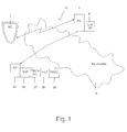
- Fig. 1 illustrates tracking system 10, according to one embodiment of the present invention.
- Tracking system 10 comprises a plurality of mobile devices (MD) 2, each of which is held or accessed by a corresponding user of a mobile data network, and a computing device (CD) 20 used for processing and tracking purposes.
- Base station (BS) 5 for coordinating call and data traffic through a given cell is able to interface with each of mobile devices 2 and to determine their instantaneous position by triangulation or by means of the GPS module provided with a mobile device.
- the positional data for all users is stored in Call Data Record (CDR) database 6.
- CDR Call Data Record
- CDR database 6 is stored user associated data related to each instance of cellular network activity, including calls, text messages, data usage and cell tower registration.
- the user associated data that is recorded includes the number of the calling party, the number of the called party, the time when the call started, the duration of the call, the phone number charged for the call, an indication of whether the call was answered, the route by which the communication instance entered the exchange, the route by which the communication instance left the exchange, the communication instance type, and the location of the mobile device during the communication instance.
- Computing device 20 which may be a server, has a buffer 18, a tracking database 22, a filtering module 26, and a processing module 28.
- tracking database 22 is stored a generated user-specific path for all users recorded in the CDR.
- Computing device 20 has a working agreement with base station 5 to receive via data network 15 the recently generated data stored in CDR database 6. Due to local security regulations, the user's name for each mobile device cannot be divulged; however, certain user parameters that are of benefit to the tracking system are provided.
- the received CDR data is temporarily stored in buffer 18 for a sufficient time needed by processing module 28 to process the CDR data and to thereby generate a user-specific path, as will be described hereinafter, until the received CDR data is automatically destroyed, in accordance with security regulations.
- the user-specific path is described as being generated for individuals advancing within a vehicle, but it will be appreciated that the invention is also applicable to pedestrians.
- Each CDR data object may be stored as a tuple in the form of ⁇ timestamp, user ID, cell ID>.
- the cell ID is associated with the physical location and coverage area of the cell, data which is maintained by the cellular service provider.
- Processing module 28 generates an estimated location indicator (ELI) for each received CDR data object.
- ELI estimated location indicator
- FIG. 2 schematically illustrates a grid 25 of cells 31-42 in an urban area.
- Each line 29 represents a corresponding road within the urban area which may extend from one cell to another, or alternatively its route may be limited to the physical location of a single cell.
- the received CDR data is processed so as to define, for the same user ID, a plurality of ELIs A-C, each of which is associated with a different timestamp and cell ID.
- ELI A has been assigned to cell [0,0], B to cell [0,2] and C to cell [2,3].
- Estimated path 44 is generated from A to B and estimated path 45 is generated from B to C.
- the actual path along which the user traveled may have been considerably different than the estimated path that was generated, often constituting a discrepancy of approximately half a cell width and rendering tracked information to be unreliable.
- various tangible points of interest such as parks, buildings, restaurants, and train stations are generally found in each cell, and may capture the attention of a user or alternatively may cause the user to travel in a direction away from the tangible element.
- the presence of a point of interest within a cell further adds to the uncertainty as to the path of a user.
- the timestamp provided by the CDR data helps to define the elapsed time difference of a trip from one ELI to another.
- a plurality of transitional points between adjacent cells are predefined, preferably offline, e.g. transitional point 43 shown in Fig. 2 .
- Each of the transitional points which are located at the intersection of a road and a cell border whereat a large number of vehicles pass when traveling between adjacent cells, constitutes a logical constraint for the processing module to predict the shortest predicted path while passing through a transitional point.
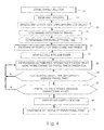
- Fig. 4 illustrates the tracking method, according to one embodiment of the invention.
- the CDR data is received in step 51.
- the processing module extracts data having a common user ID in step 53 and generates an ELI for each corresponding CDR data object, for example in a different cell.
- the direction of travel is determined in step 55 and the time of travel from one cell to another is determined in step 57.
- the filtering module filters out in step 59 all one-way roads that extend in an opposite direction than the direction of travel from a first ELI to a second ELI.
- Each cell may be divided into a predetermined number of subzones in step 61, for each of which an iteratable ELI is generated.
- the number of iteratable ELIs is generally greater than the number of transitional points.
- the processing module performs an iterative pair-wise process whereby one ELI is selected from each cell and from one of the subzones, and the estimated time to travel between the two ELIs is compared with the CDR-derived time of travel.
- the estimated time of travel is generally dependent on the known number of traffic lights between the two selected ELIs, the average waiting time at each traffic light, and the resulting average travel time.
- step 65 If the estimated time to travel between the two ELIs does not match the CDR-derived time of travel, a different pair of ELIs is examined in step 65, one from each cell and from one of the subzones. After two ELIs are provisionally found between which the estimated time to travel matches the CDR-derived time of travel, the two provisionally selected ELIs are filtered out in step 67 if the predicted path therebetween does not pass through a transitional point. Step 63 is repeated until the predicted path passes through a transitional point, while taking into account various heuristic considerations.
- step 69 the location for the given user at a given time is identified in step 69 as coinciding with the transitional point related to the predicted path, and likewise the number of people at a given time and at the given transitional point is then counted in step 71.
- the predicted path may be more accurate when CDR data for three or more different cells is employed, allowing the possibilities for the shortest predicted path between cells to be narrowed by being able to more accurately match the corresponding estimated time to travel with the inter-cell, CDR-derived time of travel.
- an aggregation model may be implemented for the aforementioned tracking method, in order to reduce computer resources by eliminating the need of having to repeat an iterative process for a large number of people, particularly those located in an urban area or in the vicinity or a public transportation station or traveling along a particular route.
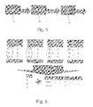
- data provider 74 e.g. a base station, generates CDR data for each of a large number of people and transmits it to aggregator module 76 of the computing device.
- Aggregator module 76 relies on data generated by road path matcher 78 associated with the processing module to output the results.
- Aggregator module 76 is able to perform the following functions for a given time frame: (1) retrieve a user-specific path, (2) identify all other users that traversed the same path and at the same transitional point, and (3) cluster the identified people into groups according to the duration of the path traversing event.
- Fig. 6 illustrates an exemplary aggregation operation performed by the aggregator module.
- Person 1 exited Cell A via a transitional point after 10 minutes, Cell B after 20 minutes, and Cell C after 33 minutes for an average traveling time of 23 minutes.
- Person 2 exited Cell A after 15 minutes, Cell B after 25 minutes, and Cell C after 32 minutes, for an average traveling time of 17 minutes.
- Person 3 exited Cell A after 19 minutes, Cell B after 25 minutes, and Cell C after 50 minutes, for an average traveling time of 31 minutes.
- Person 4 exited Cell A after 10 minutes, Cell B after 25 minutes, and Cell C after 41 minutes, for an average traveling time of 29 minutes.
- the aggregator module then partitions, by K-means clustering, the average traveling time of each person to the cluster with the closest mean time. Any algorithm known to those skilled in the art for clustering is suitable. Thus in this example two people have been aggregated in each of the two average groups.
- the mean time of each average group is then matched with a path extending from Cell A to Cell B and then to Cell C which is associated with a corresponding estimated time, for example as described hereinabove with respect to Fig. 4 ..
- Calculation time and the amount of needed computer resources are reduced for the path matching phase by aggregating the received data and having to calculate a unique cell path only once for a unique cell path.
- An Estimated Location Indicator (ELI) associated with a data object in each of every cell of the grid traversed by the corresponding user within a given period of time is generated, from the received positional data records and for each corresponding user of the plurality of mobile devices.
- a shortest predicted path is generated between each of the generated An Estimated Location Indicators.
Landscapes
- Engineering & Computer Science (AREA)
- Radar, Positioning & Navigation (AREA)
- Remote Sensing (AREA)
- Computer Networks & Wireless Communication (AREA)
- Signal Processing (AREA)
- Automation & Control Theory (AREA)
- Physics & Mathematics (AREA)
- General Physics & Mathematics (AREA)
- Traffic Control Systems (AREA)
- Navigation (AREA)
- Mobile Radio Communication Systems (AREA)
Abstract
Description
- The present invention relates to the field of monitoring systems. More particularly, the invention relates to a system and method for tracking the whereabouts of people, particularly in urban settings.
- The ability to continuously track the whereabouts of people can be very useful to security personnel, to those conducting advertisement related marketing studies, and for determining a concentration of pedestrian or vehicle traffic, and can even be life saving, for example following a catastrophic event.
- However, a system that provides continuous and quickly reacting tracking services requires expensive tracking and processing equipment, and additionally imposes a large load on its computer resources due to the need of maintaining a database for each person being tracked as a result of the huge amount of information that has to be saved.
- It is an object of the present invention to provide a system for continuously tracking the whereabouts of people that is considerably more inexpensive to maintain than one of the prior art.
- It is an additional object of the present invention to provide a method for continuously tracking the whereabouts of people that requires considerably less computer resources than one of the prior art.
- Other objects and advantages of the invention will become apparent as the description proceeds.
- The present invention provides a method for tracking the whereabouts of people, particularly in urban settings, comprising the steps of establishing a cell grid within a given geographical region; receiving positional data records associated with each of a plurality of mobile devices within said region, from a base station; generating, from said received positional data records and for each corresponding user of said plurality of mobile devices, an estimated location indicator (ELI) associated with a data object in each of every cell of said grid traversed by said corresponding user within a given period of time; and generating a shortest predicted path between each of said generated ELIs.
- The present invention is also directed to a system for tracking the whereabouts of people, particularly in urban settings, comprising a plurality of mobile devices, each of which held or accessed by a corresponding user of a mobile data network; a base station for coordinating call and data traffic with respect to said plurality of mobile devices within a given geographical region in which a cell grid has been established and for generating positional data records associated with each of said plurality of mobile devices within said region; and a computing device for receiving said positional data records, for generating, from said received positional data records and for each corresponding user of said plurality of mobile devices, an estimated location indicator (ELI) associated with a data object in each of every cell of said grid traversed by said corresponding user within a given period of time, and for generating a shortest predicted path between each of said generated ELIs.
- In the drawings:
-
Fig. 1 is a schematic illustration of a tracking system, according to one embodiment of the present invention; -
Fig. 2 is a schematic illustration of a cell grid, on which is overlaid a road system and a plurality of transitional points; -
Fig. 3 is a schematic illustration of the cell grid ofFig. 2 , showing the generation of a plurality of estimated location indicators and of an estimated path extending therebetween; -
Fig. 4 is a flow diagram of a tracking method, according to one embodiment of the invention; -
Fig. 5 is a block diagram of an aggregation model which may be implemented for the tracking method ofFig. 4 ; and -
Fig. 6 is an exemplary aggregation operation performed by the aggregation model ofFig. 5 . - The system and method of the present invention provide continuous people tracking capabilities over a mobile data network while reducing the required amount of computer resources by obtaining region related data for a person being monitored at each of different times and then generating a shortest predicted path between the corresponding points. This method has great utility in urban settings at which a person has much freedom in deciding a desired path.
- The network over which the mobile devices communicate is described as being a cellular network, but it will be appreciated that the invention is similarly applicable to other networks as well.
-
Fig. 1 illustratestracking system 10, according to one embodiment of the present invention.Tracking system 10 comprises a plurality of mobile devices (MD) 2, each of which is held or accessed by a corresponding user of a mobile data network, and a computing device (CD) 20 used for processing and tracking purposes. Base station (BS) 5 for coordinating call and data traffic through a given cell is able to interface with each ofmobile devices 2 and to determine their instantaneous position by triangulation or by means of the GPS module provided with a mobile device. The positional data for all users is stored in Call Data Record (CDR)database 6. - In
CDR database 6 is stored user associated data related to each instance of cellular network activity, including calls, text messages, data usage and cell tower registration. The user associated data that is recorded includes the number of the calling party, the number of the called party, the time when the call started, the duration of the call, the phone number charged for the call, an indication of whether the call was answered, the route by which the communication instance entered the exchange, the route by which the communication instance left the exchange, the communication instance type, and the location of the mobile device during the communication instance. -
Computing device 20, which may be a server, has abuffer 18, atracking database 22, afiltering module 26, and aprocessing module 28. Intracking database 22 is stored a generated user-specific path for all users recorded in the CDR. -
Computing device 20 has a working agreement withbase station 5 to receive viadata network 15 the recently generated data stored inCDR database 6. Due to local security regulations, the user's name for each mobile device cannot be divulged; however, certain user parameters that are of benefit to the tracking system are provided. The received CDR data is temporarily stored inbuffer 18 for a sufficient time needed by processingmodule 28 to process the CDR data and to thereby generate a user-specific path, as will be described hereinafter, until the received CDR data is automatically destroyed, in accordance with security regulations. - In the following description, the user-specific path is described as being generated for individuals advancing within a vehicle, but it will be appreciated that the invention is also applicable to pedestrians.
- Each CDR data object may be stored as a tuple in the form of <timestamp, user ID, cell ID>. The cell ID is associated with the physical location and coverage area of the cell, data which is maintained by the cellular service provider.
Processing module 28 generates an estimated location indicator (ELI) for each received CDR data object. - In order to appreciate the method of the present invention, reference is now made to
Fig. 2 , which schematically illustrates agrid 25 of cells 31-42 in an urban area. Eachline 29 represents a corresponding road within the urban area which may extend from one cell to another, or alternatively its route may be limited to the physical location of a single cell. - Due to the large number of possibilities for travelling from one location to another, a user-specific path cannot be easily predicted.
- As schematically illustrated in
Fig. 3 , the received CDR data is processed so as to define, for the same user ID, a plurality of ELIs A-C, each of which is associated with a different timestamp and cell ID. For example, ELI A has been assigned to cell [0,0], B to cell [0,2] and C to cell [2,3]. Estimatedpath 44 is generated from A to B and estimatedpath 45 is generated from B to C. However, the actual path along which the user traveled may have been considerably different than the estimated path that was generated, often constituting a discrepancy of approximately half a cell width and rendering tracked information to be unreliable. - In addition, various tangible points of interest such as parks, buildings, restaurants, and train stations are generally found in each cell, and may capture the attention of a user or alternatively may cause the user to travel in a direction away from the tangible element. Thus the presence of a point of interest within a cell further adds to the uncertainty as to the path of a user.
- In the method of the present invention, the timestamp provided by the CDR data helps to define the elapsed time difference of a trip from one ELI to another. To further reduce the number of possibilities concerning along which route the user travelled, a plurality of transitional points between adjacent cells are predefined, preferably offline, e.g.
transitional point 43 shown inFig. 2 . Each of the transitional points, which are located at the intersection of a road and a cell border whereat a large number of vehicles pass when traveling between adjacent cells, constitutes a logical constraint for the processing module to predict the shortest predicted path while passing through a transitional point. -
Fig. 4 illustrates the tracking method, according to one embodiment of the invention. After a cell grid has been established instep 49, including the definition of cell IDs, cell borders, roads passing through the various cells, and transitional points, the CDR data is received instep 51. The processing module extracts data having a common user ID instep 53 and generates an ELI for each corresponding CDR data object, for example in a different cell. By referring to the time stamp of each CDR data object, the direction of travel is determined instep 55 and the time of travel from one cell to another is determined instep 57. The filtering module then filters out instep 59 all one-way roads that extend in an opposite direction than the direction of travel from a first ELI to a second ELI. - Each cell may be divided into a predetermined number of subzones in
step 61, for each of which an iteratable ELI is generated. For each cell, the number of iteratable ELIs is generally greater than the number of transitional points. Instep 63, the processing module performs an iterative pair-wise process whereby one ELI is selected from each cell and from one of the subzones, and the estimated time to travel between the two ELIs is compared with the CDR-derived time of travel. The estimated time of travel is generally dependent on the known number of traffic lights between the two selected ELIs, the average waiting time at each traffic light, and the resulting average travel time. If the estimated time to travel between the two ELIs does not match the CDR-derived time of travel, a different pair of ELIs is examined instep 65, one from each cell and from one of the subzones. After two ELIs are provisionally found between which the estimated time to travel matches the CDR-derived time of travel, the two provisionally selected ELIs are filtered out instep 67 if the predicted path therebetween does not pass through a transitional point.Step 63 is repeated until the predicted path passes through a transitional point, while taking into account various heuristic considerations. Accordingly, the location for the given user at a given time is identified instep 69 as coinciding with the transitional point related to the predicted path, and likewise the number of people at a given time and at the given transitional point is then counted instep 71. - The predicted path may be more accurate when CDR data for three or more different cells is employed, allowing the possibilities for the shortest predicted path between cells to be narrowed by being able to more accurately match the corresponding estimated time to travel with the inter-cell, CDR-derived time of travel.
- In another embodiment schematically illustrated in
Fig. 5 , an aggregation model may be implemented for the aforementioned tracking method, in order to reduce computer resources by eliminating the need of having to repeat an iterative process for a large number of people, particularly those located in an urban area or in the vicinity or a public transportation station or traveling along a particular route. - In the aggregation model,
data provider 74, e.g. a base station, generates CDR data for each of a large number of people and transmits it toaggregator module 76 of the computing device.Aggregator module 76 relies on data generated by road path matcher 78 associated with the processing module to output the results. -
Aggregator module 76 is able to perform the following functions for a given time frame: (1) retrieve a user-specific path, (2) identify all other users that traversed the same path and at the same transitional point, and (3) cluster the identified people into groups according to the duration of the path traversing event. -
Fig. 6 illustrates an exemplary aggregation operation performed by the aggregator module. Within a time frame of 1 hour, four people travelled from Cell A to Cell B and then to Cell C, but at different times.Person 1 exited Cell A via a transitional point after 10 minutes, Cell B after 20 minutes, and Cell C after 33 minutes for an average traveling time of 23 minutes.Person 2 exited Cell A after 15 minutes, Cell B after 25 minutes, and Cell C after 32 minutes, for an average traveling time of 17 minutes.Person 3 exited Cell A after 19 minutes, Cell B after 25 minutes, and Cell C after 50 minutes, for an average traveling time of 31 minutes.Person 4 exited Cell A after 10 minutes, Cell B after 25 minutes, and Cell C after 41 minutes, for an average traveling time of 29 minutes. - From the observed data, two mean times are identified: 20 minutes and 30 minutes. The aggregator module then partitions, by K-means clustering, the average traveling time of each person to the cluster with the closest mean time. Any algorithm known to those skilled in the art for clustering is suitable. Thus in this example two people have been aggregated in each of the two average groups.
- The mean time of each average group is then matched with a path extending from Cell A to Cell B and then to Cell C which is associated with a corresponding estimated time, for example as described hereinabove with respect to
Fig. 4 .. Calculation time and the amount of needed computer resources are reduced for the path matching phase by aggregating the received data and having to calculate a unique cell path only once for a unique cell path. - It will be appreciated that the aforementioned tracking method is also applicable to tracking pedestrians who traverse known walkways.
- While some embodiments of the invention have been described by way of illustration, it will be apparent that the invention can be carried out with many modifications, variations and adaptations, and with the use of numerous equivalents or alternative solutions that are within the scope of persons skilled in the art, without exceeding the scope of the claims.
- A method for tracking the whereabouts of people, particularly in urban settings, according to which a cell grid is established within a given geographical region and positional data records associated with each of a plurality of mobile devices within the region, are received from a base station. An Estimated Location Indicator (ELI) associated with a data object in each of every cell of the grid traversed by the corresponding user within a given period of time is generated, from the received positional data records and for each corresponding user of the plurality of mobile devices. A shortest predicted path is generated between each of the generated An Estimated Location Indicators.
Claims (7)
- A method for tracking the whereabouts of people, particularly in urban settings, comprising the steps of:a) establishing a cell grid within a given geographical region;b) receiving positional data records associated with each of a plurality of mobile devices within said region, from a base station;c) generating, from said received positional data records and for each corresponding user of said plurality of mobile devices, an Estimated Location Indicator (ELI) associated with a data object in each of every cell of said grid traversed by said corresponding user within a given period of time; andd) generating a shortest predicted path between each of said generated ELIs.
- The method according to claim 1, wherein the shortest predicted path between each of said generated ELIs is found when an ELI derived travel time is substantially equal to a data record derived travel time.
- The method according to claim 2, wherein first and second generated ELIs are located in different cells of said grid.
- The method according to claim 1, further comprising the steps of determining a direction of travel and filtering out all one-way roads extending in an opposite direction to said determined direction of travel, prior to the step of generating a shortest predicted path.
- The method according to claim 1, wherein the predicted path passes through a transitional point through cells.
- The method according to claim 1, wherein the predicted path is found by performing a pair-wise iterative process while generating an estimated travel time between ELIs.
- A system for tracking the whereabouts of people, particularly in urban settings, comprising:a) a plurality of mobile devices, each of which held or accessed by a corresponding user of a mobile data network;b) a base station for coordinating call and data traffic with respect to said plurality of mobile devices within a given geographical region in which a cell grid has been established and for generating positional data records associated with each of said plurality of mobile devices within said region; andc) a computing device for receiving said positional data records, for generating, from said received positional data records and for each corresponding user of said plurality of mobile devices, an estimated location indicator (ELI) associated with a data object in each of every cell of said grid traversed by said corresponding user within a given period of time, and for generating a shortest predicted path between each of said generated ELIs.
Applications Claiming Priority (1)
| Application Number | Priority Date | Filing Date | Title |
|---|---|---|---|
| IL22981413 | 2013-12-05 |
Publications (1)
| Publication Number | Publication Date |
|---|---|
| EP2881711A1 true EP2881711A1 (en) | 2015-06-10 |
Family
ID=52272814
Family Applications (1)
| Application Number | Title | Priority Date | Filing Date |
|---|---|---|---|
| EP14195798.5A Ceased EP2881711A1 (en) | 2013-12-05 | 2014-12-02 | A method and system for tracking the whereabouts of people in urban settings |
Country Status (2)
| Country | Link |
|---|---|
| US (1) | US9420427B2 (en) |
| EP (1) | EP2881711A1 (en) |
Families Citing this family (2)
| Publication number | Priority date | Publication date | Assignee | Title |
|---|---|---|---|---|
| CN109426791B (en) * | 2017-09-01 | 2022-09-16 | 深圳市金溢科技股份有限公司 | Multi-site and multi-vehicle matching method, server and system |
| CN116723231B (en) * | 2023-07-31 | 2025-08-26 | 杭州云深科技有限公司 | A data processing system based on multi-source heterogeneous data |
Citations (1)
| Publication number | Priority date | Publication date | Assignee | Title |
|---|---|---|---|---|
| US20130304363A1 (en) * | 2012-05-08 | 2013-11-14 | International Business Machines Corporation | Identifying purpose-based origin-destination using call detailed records |
Family Cites Families (3)
| Publication number | Priority date | Publication date | Assignee | Title |
|---|---|---|---|---|
| FI118614B (en) * | 2005-12-27 | 2008-01-15 | Navicore Oy | A method for detecting errors in navigation data |
| US8812018B2 (en) * | 2010-07-28 | 2014-08-19 | Unwired Planet, Llc | System and method for predicting future locations of mobile communication devices using connection-related data of a mobile access network |
| US9459112B2 (en) * | 2013-03-15 | 2016-10-04 | Vivint, Inc. | Security system with traffic monitoring |
-
2014
- 2014-11-24 US US14/551,112 patent/US9420427B2/en active Active
- 2014-12-02 EP EP14195798.5A patent/EP2881711A1/en not_active Ceased
Patent Citations (1)
| Publication number | Priority date | Publication date | Assignee | Title |
|---|---|---|---|---|
| US20130304363A1 (en) * | 2012-05-08 | 2013-11-14 | International Business Machines Corporation | Identifying purpose-based origin-destination using call detailed records |
Also Published As
| Publication number | Publication date |
|---|---|
| US9420427B2 (en) | 2016-08-16 |
| US20150163638A1 (en) | 2015-06-11 |
Similar Documents
| Publication | Publication Date | Title |
|---|---|---|
| Jiao et al. | Impacts of COVID-19 on bike-sharing usages in Seoul, South Korea | |
| EP3335209B1 (en) | Method and system for computing an o-d matrix obtained through radio mobile network data | |
| Wang et al. | Estimating dynamic origin-destination data and travel demand using cell phone network data | |
| CN103854472B (en) | Taxi cloud intelligent dispatching method and system | |
| EP2608181B1 (en) | Method for detecting traffic | |
| CN103035123B (en) | Abnormal data acquisition methods and system in a kind of traffic track data | |
| US8843157B2 (en) | Dynamic travel behavior estimation in mobile network | |
| Holleczek et al. | Detecting weak public transport connections from cellphone and public transport data | |
| CN105792134B (en) | Method and device for carpooling | |
| Yang et al. | Detecting home and work locations from mobile phone cellular signaling data | |
| WO2015096379A1 (en) | Bus station optimization evaluation method and system | |
| US20130166352A1 (en) | Mobile categorization | |
| CN111882867A (en) | City wisdom traffic early warning system based on thing networking | |
| Horn et al. | QZTool—automatically generated origin-destination matrices from cell phone trajectories | |
| CN103150156A (en) | Method and system, based on geographic model and moving track, for obtaining characteristic crowd in real time | |
| Sadeghinasr et al. | Estimating commuting patterns from high resolution phone GPS data | |
| Horn et al. | Deriving public transportation timetables with large-scale cell phone data | |
| CN103891319A (en) | Method and device for determining a location for a charging station | |
| Holleczek et al. | Traffic measurement and route recommendation system for mass rapid transit (mrt) | |
| Li et al. | Public transportation mode detection from cellular data | |
| Liu et al. | Data analysis and mining of traffic features based on taxi GPS trajectories: A case study in Beijing | |
| CN104599499B (en) | A kind of method and device of distributed statistics traffic location | |
| Li et al. | Estimating crowd flow and crowd density from cellular data for mass rapid transit | |
| Roopa et al. | Crotis-crowdsourcing based traffic information system | |
| CN104361746A (en) | Intelligent highway traffic monitoring method |
Legal Events
| Date | Code | Title | Description |
|---|---|---|---|
| PUAI | Public reference made under article 153(3) epc to a published international application that has entered the european phase |
Free format text: ORIGINAL CODE: 0009012 |
|
| 17P | Request for examination filed |
Effective date: 20141202 |
|
| AK | Designated contracting states |
Kind code of ref document: A1 Designated state(s): AL AT BE BG CH CY CZ DE DK EE ES FI FR GB GR HR HU IE IS IT LI LT LU LV MC MK MT NL NO PL PT RO RS SE SI SK SM TR |
|
| AX | Request for extension of the european patent |
Extension state: BA ME |
|
| R17P | Request for examination filed (corrected) |
Effective date: 20151209 |
|
| RBV | Designated contracting states (corrected) |
Designated state(s): AL AT BE BG CH CY CZ DE DK EE ES FI FR GB GR HR HU IE IS IT LI LT LU LV MC MK MT NL NO PL PT RO RS SE SI SK SM TR |
|
| STAA | Information on the status of an ep patent application or granted ep patent |
Free format text: STATUS: EXAMINATION IS IN PROGRESS |
|
| 17Q | First examination report despatched |
Effective date: 20180417 |
|
| STAA | Information on the status of an ep patent application or granted ep patent |
Free format text: STATUS: THE APPLICATION HAS BEEN REFUSED |
|
| 18R | Application refused |
Effective date: 20211123 |