EP2881624A1 - Cooling tubing for winding - Google Patents
Cooling tubing for winding Download PDFInfo
- Publication number
- EP2881624A1 EP2881624A1 EP13825550.0A EP13825550A EP2881624A1 EP 2881624 A1 EP2881624 A1 EP 2881624A1 EP 13825550 A EP13825550 A EP 13825550A EP 2881624 A1 EP2881624 A1 EP 2881624A1
- Authority
- EP
- European Patent Office
- Prior art keywords
- tubing
- cooling
- winding
- angular
- cooled
- Prior art date
- Legal status (The legal status is an assumption and is not a legal conclusion. Google has not performed a legal analysis and makes no representation as to the accuracy of the status listed.)
- Withdrawn
Links
Images



Classifications
-
- F—MECHANICAL ENGINEERING; LIGHTING; HEATING; WEAPONS; BLASTING
- F16—ENGINEERING ELEMENTS AND UNITS; GENERAL MEASURES FOR PRODUCING AND MAINTAINING EFFECTIVE FUNCTIONING OF MACHINES OR INSTALLATIONS; THERMAL INSULATION IN GENERAL
- F16H—GEARING
- F16H57/00—General details of gearing
- F16H57/04—Features relating to lubrication or cooling or heating
- F16H57/0412—Cooling or heating; Control of temperature
- F16H57/0415—Air cooling or ventilation; Heat exchangers; Thermal insulations
- F16H57/0417—Heat exchangers adapted or integrated in the gearing
-
- F—MECHANICAL ENGINEERING; LIGHTING; HEATING; WEAPONS; BLASTING
- F28—HEAT EXCHANGE IN GENERAL
- F28F—DETAILS OF HEAT-EXCHANGE AND HEAT-TRANSFER APPARATUS, OF GENERAL APPLICATION
- F28F1/00—Tubular elements; Assemblies of tubular elements
- F28F1/02—Tubular elements of cross-section which is non-circular
- F28F1/04—Tubular elements of cross-section which is non-circular polygonal, e.g. rectangular
-
- F—MECHANICAL ENGINEERING; LIGHTING; HEATING; WEAPONS; BLASTING
- F28—HEAT EXCHANGE IN GENERAL
- F28D—HEAT-EXCHANGE APPARATUS, NOT PROVIDED FOR IN ANOTHER SUBCLASS, IN WHICH THE HEAT-EXCHANGE MEDIA DO NOT COME INTO DIRECT CONTACT
- F28D15/00—Heat-exchange apparatus with the intermediate heat-transfer medium in closed tubes passing into or through the conduit walls ; Heat-exchange apparatus employing intermediate heat-transfer medium or bodies
-
- F—MECHANICAL ENGINEERING; LIGHTING; HEATING; WEAPONS; BLASTING
- F28—HEAT EXCHANGE IN GENERAL
- F28D—HEAT-EXCHANGE APPARATUS, NOT PROVIDED FOR IN ANOTHER SUBCLASS, IN WHICH THE HEAT-EXCHANGE MEDIA DO NOT COME INTO DIRECT CONTACT
- F28D21/00—Heat-exchange apparatus not covered by any of the groups F28D1/00 - F28D20/00
- F28D2021/0019—Other heat exchangers for particular applications; Heat exchange systems not otherwise provided for
- F28D2021/0028—Other heat exchangers for particular applications; Heat exchange systems not otherwise provided for for cooling heat generating elements, e.g. for cooling electronic components or electric devices
-
- F—MECHANICAL ENGINEERING; LIGHTING; HEATING; WEAPONS; BLASTING
- F28—HEAT EXCHANGE IN GENERAL
- F28D—HEAT-EXCHANGE APPARATUS, NOT PROVIDED FOR IN ANOTHER SUBCLASS, IN WHICH THE HEAT-EXCHANGE MEDIA DO NOT COME INTO DIRECT CONTACT
- F28D7/00—Heat-exchange apparatus having stationary tubular conduit assemblies for both heat-exchange media, the media being in contact with different sides of a conduit wall
- F28D7/005—Heat-exchange apparatus having stationary tubular conduit assemblies for both heat-exchange media, the media being in contact with different sides of a conduit wall the conduits for only one medium being tubes having bent portions or being assembled from bent tubes or being tubes having a toroidal configuration
-
- F—MECHANICAL ENGINEERING; LIGHTING; HEATING; WEAPONS; BLASTING
- F28—HEAT EXCHANGE IN GENERAL
- F28F—DETAILS OF HEAT-EXCHANGE AND HEAT-TRANSFER APPARATUS, OF GENERAL APPLICATION
- F28F7/00—Elements not covered by group F28F1/00, F28F3/00 or F28F5/00
Definitions
- the present invention relates to a cooling tubing for winding that is wound around an outer surface of an object to be cooled, such as a reduction gear (hereinafter simply referred to as a reduction gear), which is provided in a machine tool or the like (hereinafter simply referred to as a machine tool) and cools the reduction gear through a cooling medium within the tubing.
- a reduction gear hereinafter simply referred to as a reduction gear
- a machine tool a machine tool
- the reduction gear is often cooled by winding a tubing for allowing cooling water (cooling medium) to pass therethrough around the reduction gear in order to reduce a bad influence on a mechanism portion of a machine tool caused by heat generation of a reduction gear.
- a tubing made of a copper pipe or a resinous hose of which the cross-sectional shape is a circular tubular shape is wound around the reduction gear or the like.
- the cooling water By passing the cooling water through this tubing, the reduction gear is cooled so that abnormal heat generation is prevented.
- Fig. 7 is a cutaway perspective view of essential parts of the related-art cooling tubing for winding.
- Fig. 8 is a cross-sectional view taken along line VIII-VIII of Fig. 7 , illustrating only key points.
- a related-art cooling tubing for winding 10 has a cooling tubing 18 made of a copper pipe of which the cross-sectional shape is a circular tubular shape.
- the cooling tubing 18 is wound in parallel around an outer surface 9S of a reduction gear (object to be cooled) 9 having an input shaft 9A and an output shaft 9B, and is fixed to a fixing portion (not illustrated).
- Cooling water (cooling medium) from a cooling water supply device (not illustrated) is passed through the cooling tubing 18.
- the reduction gear 9 is cooled by the passing of the cooling water through the cooling tubing 18.
- the related-art cooling tubing for winding 10 By passing the cooling water through the cooling tubing 18 at a proper flow rate, the reduction gear 9 is cooled by heat transfer via a contact portion 18P between an outer surface of the cooling tubing 18 and the outer surface 9S of the reduction gear 9.
- the cross-sectional shape of the cooling tubing 18 is a circular tubular shape in the technique of such a related-art cooling tubing for winding 10, the contact portion 18P is close to line contact and the heat transfer area is small. Therefore, the cooling efficiency is not so high.
- Fig. 9 is a cutaway cross-sectional view of essential parts of the other related-art cooling tubing for winding.
- Fig. 10 is a cross-sectional view taken along line X-X of Fig. 9 , illustrating only key points.
- a related-art cooling tubing for winding 11 has a cooling tubing 19 made of a copper pipe of which the cross-sectional shape is a circular tubular shape.
- the cooling tubing 19 is wound at proper intervals around the outer surface 9S of the reduction gear.
- the cooling tubing 19 is attached to the outer surface 9S of the reduction gear with tubing stoppers 22 and fastening parts 23.
- the related-art cooling tubing for winding 11 By passing the cooling water through the cooling tubing 19 at a proper flow rate, the reduction gear 9 is cooled by heat transfer via a contact portion 19P between an outer surface of the cooling tubing 19 and the outer surface 9S of the reduction gear 9. Since the cooling tubing 19 is attached to the outer surface 9S of the reduction gear with the tubing stoppers 22 and the fastening parts 23, the cooling tubing will not come off due to the vibration or the like of the reduction gear.
- the cooling tubing 19 is attached to the reduction gear with the tubing stoppers 22 and the fastening parts 23. Therefore, there is a concern that tapping work or the like for the fastening parts 23 is required, and substantial time, that is, substantial cost is required for the attachment of the tubing stoppers 22, the cooling tubing 19 cannot be wound in parallel in a substantially close contact state, and arrangement efficiency is lowered and the cooling efficiency of the reduction gear 9 is low.
- An object of the invention is to provide a cooling tubing for winding that can improve cooling efficiency in view of the above-described situation.
- the cooling efficiency can be improved.
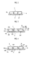
- Fig. 1 is a cutaway perspective view of essential parts of a cooling tubing for winding related to a first embodiment of the invention.
- Fig. 2 is a cross-sectional view taken along line II-II of Fig. 1 , illustrating only key points.
- Figs. 1 and 2 those having the same structure as those of a related-art cooling tubing for winding 10 described earlier will be designated by the same reference numerals, and duplicate description will be omitted.
- a cooling tubing for winding 1 has cooling tubing 8 of which the cross-sectional shape is a quadrangular tubular shape.
- the cooling tubing 8 is wound in parallel around an outer surface 9S of a reduction gear (object to be cooled) 9, and is fixed to a fixing portion (not illustrated).
- Cooling water which is a cooling medium from a cooling water supply device (not illustrated) is passed through the cooling tubing 8.
- the reduction gear 9 is cooled by the passing of the cooling water through the cooling tubing 8.
- the cooling tubing 8 is formed of a pipe of a material having excellent heat transfer capability, such as copper or aluminum, and is a drawn material drawn using a drawing mold.
- the material of the cooling tubing 8 is not limited to the drawn material of copper or aluminum.
- the cooling tubing 8, for example, may be a plastic pipe or the like in which a rubber hose or metal powder is mixed or may be a material according to the concept of the invention, and the detailed description thereof will be omitted.
- the reduction gear 9 is cooled by heat transfer via a contact portion 8P between an outer surface of the cooling tubing 8 and the outer surface 9S of the reduction gear 9.
- the cross-sectional shape of the cooling tubing 8 is an angular tubular shape.
- the contact portion 8P comes into surface contact with the outer surface 9S of the reduction gear 9 over a wide range, and a heat transfer area increases.
- cooling efficiency can be enhanced more than when a tubing of which the cross-sectional shape is a circular tubular shape is used.
- the width of the contact portion 8P is appropriately selected depending on the relationship between the cooling efficiency and the winding working efficiency of the cooling tubing 8 or the like.
- Fig. 3 is a cross-sectional view equivalent to Fig. 2 , illustrating the cooling tubing for winding related to the second embodiment of the invention.
- a cooling tubing for winding 2 has cooling tubing 28.
- the cooling tubing 28 is a tubing in which stepped portions 28A and 28B are formed in mutually facing outer surfaces among four outer surfaces of the tubing of which the cross-sectional shape is a quadrangular shape, and no stepped portion is formed in the remaining outer surfaces.
- the stepped portions 28A and 28B are formed by first surfaces 28a and 28d and second surfaces 28b and 28e substantially perpendicular to the outer surfaces in which the stepped portions are not formed, and stepped surfaces 28c and 28f substantially perpendicular to the first surfaces 28a and 28d and the second surfaces 28b and 28e.
- the first surfaces 28a and 28d are connected to the edge of one outer surface of the pair of outer surfaces in which the stepped portions are not formed, and the second surfaces 28b and 28e are connected to the edge of the other outer surface of the pair of outer surfaces.
- the second surfaces 28b and 28e are formed at positions shifted with respect to the first surfaces 28a and 28d in directions in which the outer surfaces in which the stepped portions are not formed widen.
- the stepped surfaces 28c and 28f are surfaces that connect the edges of the first surfaces 28a and 28d and the edges of the second surfaces 28b and 28e.
- the spacing between the first surface 28a of the stepped portion 28A and the first surface 28d of the stepped portion 28B and the spacing between the second surface 28b of the stepped portion 28A and the second surface 28e of the stepped portion 28B are almost the same. For this reason, when the first surface 28a of the stepped portion 28A is located on an outward side of the tubing with respect to the second surface 28b of the stepped portion 28A, the first surface 28d of the stepped portion 28B is located on an inward side of the tubing with respect to the second surface 28e of the stepped portion 28B.
- the cooling tubing 28 is wound in parallel around the outer surface 9S so that the outer surfaces in which the stepped portions 28A and 28B are not formed face the outer surface 9S of the reduction gear 9.
- the stepped surface 28c of the stepped portion 28A faces and overlaps the stepped surface 28f of the stepped portion 28B in the cooling tubing 28 in the adjacent row.
- the cooling water from the cooling water supply device (not illustrated) is passed through the cooling tubing 28.
- the reduction gear 9 is cooled by the passing of the cooling water through the cooling tubing 28.
- the cooling tubing 28 is formed of a pipe of a material having excellent heat transfer capability, such as copper or aluminum, and is a drawn material drawn using a drawing mold.
- the material of the cooling tubing 28 is not limited to the drawn material of copper or aluminum.
- the cooling tubing 28, for example, may be a plastic pipe or the like in which a rubber hose or metal powder is mixed or may be a material according to the concept of the invention, and the detailed description thereof will be omitted.
- the reduction gear 9 is cooled by heat transfer via a contact portion 28P between the cooling tubing 28 and the outer surface 9S of the reduction gear 9, like the aforementioned first embodiment.
- the stepped portion 28A of the cooling tubing 28 overlaps the stepped portion 28B of the cooling tubing 28 in the adjacent row in the direction along the outer surface 9S of the reduction gear 9, and the cooling tubing 28 is wound around the outer surface 9S of the reduction gear 9.
- the attachment of the reduction gear 9 to the outer surface 9S is easy, and the working efficiency of winding to an outer surface of an object to be cooled is excellent.
- the stepped portions 28A and 28B also serve as a fixing function for the winding to the outer surface of the object to be cooled. Therefore, the number of the tubing stoppers as in the related art can be markedly reduced.
- the inner cross-sectional shape of the cooling tubing 28 is a quadrangular shape.
- the inner cross-sectional shape of the cooling tubing 28 may not be a quadrangular shape or may be a shape similar to an outer cross-sectional shape. It is needless to say that the inner cross-sectional shape of the cooling tubing may be selected in consideration of the cooling efficiency obtained by the cooling water passing through the cooling tubing, the productivity of the material by the drawing mold, or the like.
- Fig. 4 is a cross-sectional view equivalent to Fig. 3 , illustrating the cooling tubing for winding related to the third embodiment of the invention.
- a cooling tubing for winding 3 has cooling tubing 38.
- the cooling tubing 38 similar to the cooling tubing 28 in the second embodiment, is a tubing in which stepped portions 38A and 38B are formed in mutually facing outer surfaces among four outer surfaces of the tubing of which the cross-sectional shape is a quadrangular shape, and no stepped portion is formed in the remaining outer surfaces.
- a convex plugging portion 38M is formed on a stepped surface 38c of the stepped portion 38A of one outer surface in the cooling tubing 38.
- a concave plugged portion 38F is formed in a stepped surface 38f of the stepped portion 38B of the other outer surface.
- the cooling tubing 38 is wound in parallel around the outer surface 9S of the reduction gear 9 so that the outer surfaces in which the stepped portions 38A and 38B are not formed face the outer surface 9S.
- the stepped portion 38A of the cooling tubing 38 is overlapped with the stepped portion 38B of the cooling tubing 38 in the adjacent row, and the plugging portion 38M of one stepped portion 38A of the overlapping stepped portions is fitted into the plugged portion 38F of the other stepped portion 38B.
- the cooling water from the cooling water supply device (not illustrated) is passed through the cooling tubing 38.
- the reduction gear 9 is cooled by the passing of the cooling water through the cooling tubing 38.
- the cooling tubing 38 is formed of a pipe of a material having excellent heat transfer capability, such as copper or aluminum, and is a drawn material drawn using a drawing mold.
- the material of the cooling tubing 38 is not limited to the drawn material of copper or aluminum.
- the cooling tubing 38 for example, may be a plastic pipe or the like in which a rubber hose or metal powder is mixed or may be a material according to the concept of the invention, the detailed description thereof will be omitted.
- the shape dimensions of the convex plugging portion 38M and the concave plugged portion 38F are appropriately selected in consideration of the ease of plugging work and the degree of fixation by the plugging.
- the reduction gear 9 is cooled by heat transfer via a contact portion 38P between the cooling tubing 38 and the outer surface 9S of the reduction gear 9, like the aforementioned first and second embodiments.
- the cooling tubing 38 is also wound in parallel around the outer surface 9S of the reduction gear 9.
- the stepped portion 38A of the cooling tubing 38 is overlapped with the stepped portion 38B of the cooling tubing 38 in the adjacent row, and the plugging portion 38M of the stepped portion 38A is fitted into the plugged portion 38F of the other stepped portion 38B.
- the attachment of the reduction gear 9 to the outer surface 9S is easy, and the working efficiency of winding to the outer surface 9S is excellent.
- the fixation of the winding to the outer surface 9S of the reduction gear 9 can be reliably performed, and the tubing stoppers as in the related art can be eliminated.
- Fig. 5 is a cross-sectional view equivalent to Fig. 2 , illustrating the cooling tubing for winding related to the fourth embodiment of the invention.
- a cooling tubing for winding 4 has cooling tubing 48 of which the cross-sectional shape is a quadrangular tubular shape.
- the cooling tubing 48 is wound in parallel around the outer surface 9S of the reduction gear 9, and is fixed to the fixing portion (not illustrated). Cooling water, which is a cooling medium from the cooling water supply device (not illustrated) is passed through the cooling tubing 48.
- the reduction gear 9 is cooled by the passing of the cooling water through the cooling tubing 48.
- the cooling tubing 48 is formed in an angular tubular shape by crushing tubing, of which the cross-sectional shape of a material having excellent heat transfer capability, such as copper or aluminum is a circular tubular shape, into an angular shape as illustrated. For this reason, all corners of the cooling tubing 48 are rounded.
- the reduction gear 9 is cooled by heat transfer via a contact portion 48P between an outer surface of the cooling tubing 48 and the outer surface 9S of the reduction gear 9.
- the angular tubular cooling tubing 48 is obtained by using a highly-versatile and inexpensive circular tubular tubing. Therefore, the manufacturing cost of the cooling tubing for winding 4 can be kept down.
- Fig. 6 is a cross-sectional view equivalent to Fig. 2 , illustrating the cooling tubing for winding related to the fifth embodiment of the invention.
- Fig. 6(a) illustrates a state where tubing 58A of which the cross-sectional shape is a circular tubular shape is wound at proper intervals around the outer surface 9S of the reduction gear 9
- Fig. 6(b) illustrates angular tubular tubing manufactured by applying the external force P to the outside of the circular tubular tubing from the state of Fig. 6(a) to crush the circular tubular tubing in an angular shape.
- a cooling tubing for winding 5, as illustrated in Fig. 6(b) has cooling tubing 58 of which the cross-sectional shape is a quadrangular tubular shape.
- the cooling tubing 58 as illustrated in Fig. 6(a) , is formed by winding the tubing 58A of which the cross-sectional shape is a circular tubular shape at proper intervals around the outer surface 9S of the reduction gear 9, and then applying an external force P from the outside to crush and plastically deform the tubing into a quadrangular tubular cross-sectional shape.
- the corners of the quadrangular tubular cooling tubing 58 of the present embodiment are also rounded similar to the cooling tubing 48 of the fourth embodiment.
- the circular tubular tubing 58A is formed of, for example, a pipe made of material, such as copper or aluminum, which is easily subjected to bending or crushing working, that is, easily subjected to plastic working, and is excellent in heat transfer capability.
- the reduction gear 9 is cooled by heat transfer via a contact portion 58P between an outer surface of the cooling tubing 58 and the outer surface 9S.
- the angular tubular cooling tubing 58 is obtained by using a highly-versatile inexpensive circular tubular tubing. Therefore, the manufacturing cost of the cooling tubing for winding 5 can be kept down. Additionally, in the present embodiment, the tubing 58A of which the cross-sectional shape is a circular tubular shape is crushed in an angular tubular shape by the external force P after being wound around the outer surface 9S of the reduction gear 9 at proper intervals. Thus, the formation work of the angular tubing and the adaptation work to the shape of the outer surface 9S of the reduction gear 9 can be easily performed.
- the cooling efficiency of an object to be cooled can be improved.
Landscapes
- Engineering & Computer Science (AREA)
- General Engineering & Computer Science (AREA)
- Mechanical Engineering (AREA)
- Physics & Mathematics (AREA)
- Thermal Sciences (AREA)
- Geometry (AREA)
- Metal Extraction Processes (AREA)
- Heat-Exchange Devices With Radiators And Conduit Assemblies (AREA)
- General Details Of Gearings (AREA)
Abstract
The present invention has a cooling tubing (8) that is wound around an outer surface (9S) of an object (9) to be cooled and cools the object (9) to be cooled by means of a cooling medium passed therethrough. The cooling tubing (8) is an angular tubing of which the cross-sectional shape is an angular tubular shape.
Description
- The present invention relates to a cooling tubing for winding that is wound around an outer surface of an object to be cooled, such as a reduction gear (hereinafter simply referred to as a reduction gear), which is provided in a machine tool or the like (hereinafter simply referred to as a machine tool) and cools the reduction gear through a cooling medium within the tubing. Priority is claimed on Japanese Patent Application No.
2012-168306, filed July 30, 2012 - In the related art, in machine tools, the reduction gear is often cooled by winding a tubing for allowing cooling water (cooling medium) to pass therethrough around the reduction gear in order to reduce a bad influence on a mechanism portion of a machine tool caused by heat generation of a reduction gear.
- When the reduction gear is used under unfavorable conditions, such as a heavy load, further improvement in cooling efficiency according to the improvement of a tubing winding mechanism and an improvement in winding working efficiency are desired. In addition, as a related technique, there is a technique disclosed in the following PTL 1.
- [PTL 1] Japanese Unexamined Patent Application Publication No.
2002-295649 - In the related art, in the reduction gear provided in the machine tool, a tubing made of a copper pipe or a resinous hose of which the cross-sectional shape is a circular tubular shape, is wound around the reduction gear or the like. By passing the cooling water through this tubing, the reduction gear is cooled so that abnormal heat generation is prevented.
- A related-art cooling tubing for winding will be described with reference to
Figs. 7 and 8 . -
Fig. 7 is a cutaway perspective view of essential parts of the related-art cooling tubing for winding. -
Fig. 8 is a cross-sectional view taken along line VIII-VIII ofFig. 7 , illustrating only key points. - As illustrated in
Figs. 7 and 8 , a related-art cooling tubing for winding 10 has acooling tubing 18 made of a copper pipe of which the cross-sectional shape is a circular tubular shape. Thecooling tubing 18 is wound in parallel around anouter surface 9S of a reduction gear (object to be cooled) 9 having aninput shaft 9A and anoutput shaft 9B, and is fixed to a fixing portion (not illustrated). Cooling water (cooling medium) from a cooling water supply device (not illustrated) is passed through thecooling tubing 18. Thereduction gear 9 is cooled by the passing of the cooling water through thecooling tubing 18. - The operation of the related-art cooling tubing for winding 10 will be described. By passing the cooling water through the
cooling tubing 18 at a proper flow rate, thereduction gear 9 is cooled by heat transfer via acontact portion 18P between an outer surface of thecooling tubing 18 and theouter surface 9S of thereduction gear 9. - Since the cross-sectional shape of the
cooling tubing 18 is a circular tubular shape in the technique of such a related-art cooling tubing for winding 10, thecontact portion 18P is close to line contact and the heat transfer area is small. Therefore, the cooling efficiency is not so high. - Additionally, another form of the related-art cooling tubing for winding will be described with reference to
Figs. 9 and 10 . -
Fig. 9 is a cutaway cross-sectional view of essential parts of the other related-art cooling tubing for winding. -
Fig. 10 is a cross-sectional view taken along line X-X ofFig. 9 , illustrating only key points. - In
Figs. 9 and 10 , those having the same structure as those of the related-art cooling tubing for winding 10 described earlier will be designated by the same reference numerals, and illustration and description of duplicate parts will be omitted. - As illustrated in
Figs. 9 and 10 , a related-art cooling tubing for winding 11 has acooling tubing 19 made of a copper pipe of which the cross-sectional shape is a circular tubular shape. Thecooling tubing 19 is wound at proper intervals around theouter surface 9S of the reduction gear. Thecooling tubing 19 is attached to theouter surface 9S of the reduction gear withtubing stoppers 22 and fasteningparts 23. - The operation of the related-art cooling tubing for winding 11 will be described. By passing the cooling water through the
cooling tubing 19 at a proper flow rate, thereduction gear 9 is cooled by heat transfer via acontact portion 19P between an outer surface of thecooling tubing 19 and theouter surface 9S of thereduction gear 9. Since thecooling tubing 19 is attached to theouter surface 9S of the reduction gear with thetubing stoppers 22 and thefastening parts 23, the cooling tubing will not come off due to the vibration or the like of the reduction gear. - In the technique of such a related-art cooling tubing for winding 11, the
cooling tubing 19 is attached to the reduction gear with thetubing stoppers 22 and thefastening parts 23. Therefore, there is a concern that tapping work or the like for the fasteningparts 23 is required, and substantial time, that is, substantial cost is required for the attachment of thetubing stoppers 22, thecooling tubing 19 cannot be wound in parallel in a substantially close contact state, and arrangement efficiency is lowered and the cooling efficiency of thereduction gear 9 is low. - An object of the invention is to provide a cooling tubing for winding that can improve cooling efficiency in view of the above-described situation.
- In the invention of the present application, the object is achieved by the following first to fifth aspects.
- (1) A cooling tubing for winding as a first aspect includes a cooling tubing that is wound around an outer surface of an object to be cooled and cools the object to be cooled by means of a cooling medium passed therethrough. The cooling tubing is an angular tubing of which a cross-sectional shape is an angular tubular shape, and increases the area of heat transfer with the object to be cooled.
In the first aspect, the area of heat transfer with the object to be cooled can be increased, and the cooling efficiency can be improved. - (2) In the cooling tubing for winding as a second aspect based on the first aspect, the angular tubing may be a tubing formed by deforming a tubing of which a cross-sectional shape is a circular tubular shape into an angular tubular shape.
In the second aspect, the cooling efficiency can be improved, and the angular tubing can be inexpensively obtained by using a highly-versatile and inexpensive circular tubular tubing. - (3) In the cooling tubing for winding as a third aspect based on the second aspect, the angular tubing may be a tubing formed by winding a tubing of which the cross-sectional shape is a circular tubular shape around the outer surface of the object to be cooled, and then applying an external force to an outer surface of the tubing to crush and plastically deform the tubing into an angular tubular shape.
In the third aspect, the cooling efficiency can be improved, and the angular tubing can be inexpensively obtained by using a highly-versatile and inexpensive circular tubular tubing. Moreover, in the third aspect, the formation work of the angular tubing and the adaptation work to the shape of the outer surface of the object to be cooled can be easily performed. - (4) In the cooling tubing for winding as a fourth aspect based on the first aspect, the angular tubing may be a tubing in which stepped portions are formed in mutually facing surfaces among four outer surfaces of the tubing of which the cross-sectional shape is a quadrangular tubular shape, and the angular tubing may be wound substantially in parallel around the outer surface of the object to be cooled such that the outer surfaces in which the stepped portions are not formed face the outer surface of the object to be cooled and the stepped portions face and overlap the stepped portions of the adjacent angular tubing.
In the fourth aspect, similar to the above aspects, the cooling efficiency can be improved. Moreover, in the fourth aspect, the attachment to the outer surface of the object to be cooled is easy, and the working efficiency of winding to the outer surface of the object to be cooled can be enhanced. Additionally, in the fourth aspect, the stepped portions may also serve as a fixing function for the winding to the outer surface of the object to be cooled. Therefore, the number of the tubing stoppers as in the related art can be markedly reduced. - (5) In the cooling tubing for winding as a fifth aspect based on the fourth aspect, one stepped portion of the overlapping facing stepped portions may have a convex plugging portion and the other stepped portion may have a concave plugged portion. The convex plugging portion may be fitted to the concave plugged portion.
In the fifth aspect, the same effects as those of the fourth aspect can be obtained, the fixation of the winding to the outer surface of the object to be cooled can be reliably performed, and the tubing stoppers as in the related art can be eliminated. - According to the aspects related to the invention, the cooling efficiency can be improved.
-
-
Fig. 1 is a cutaway perspective view of essential parts of a cooling tubing for winding related to a first embodiment of the invention. -
Fig. 2 is a cross-sectional view taken along line II-II ofFig. 1 , illustrating only key points. -
Fig. 3 is a cross-sectional view equivalent toFig. 2 , illustrating a cooling tubing for winding related to a second embodiment of the invention. -
Fig. 4 is a cross-sectional view equivalent toFig. 3 , illustrating a cooling tubing for winding related to a third embodiment of the invention. -
Fig. 5 is a cross-sectional view equivalent toFig. 2 , illustrating a cooling tubing for winding related to a fourth embodiment of the invention. -
Fig. 6 is a cross-sectional view equivalent toFig. 2 , illustrating a cooling tubing for winding related to a fifth embodiment of the invention. -
Fig. 7 is a cutaway cross-sectional view of essential parts of a related-art cooling tubing for winding. -
Fig. 8 is a cross-sectional view taken along line VIII-VIII ofFig. 7 , illustrating only key points. -
Fig. 9 is a cutaway cross-sectional view of essential parts of another related-art cooling tubing for winding. -
Fig. 10 is a cross-sectional view taken along line X-X ofFig. 9 , illustrating only key points. - Hereinafter, embodiments of the invention will be described in detail with reference to the drawings. In addition, the invention is not limited by the embodiments. Additionally, constituent elements in the following embodiments include elements capable of being easily assumed by a person skilled in the art, or almost the same elements.
- A first embodiment of the invention will be described with reference to
Figs. 1 and2 . -
Fig. 1 is a cutaway perspective view of essential parts of a cooling tubing for winding related to a first embodiment of the invention. -
Fig. 2 is a cross-sectional view taken along line II-II ofFig. 1 , illustrating only key points. - In
Figs. 1 and2 , those having the same structure as those of a related-art cooling tubing for winding 10 described earlier will be designated by the same reference numerals, and duplicate description will be omitted. - A cooling tubing for winding 1 has cooling
tubing 8 of which the cross-sectional shape is a quadrangular tubular shape. The coolingtubing 8 is wound in parallel around anouter surface 9S of a reduction gear (object to be cooled) 9, and is fixed to a fixing portion (not illustrated). Cooling water, which is a cooling medium from a cooling water supply device (not illustrated) is passed through the coolingtubing 8. Thereduction gear 9 is cooled by the passing of the cooling water through the coolingtubing 8. - The cooling
tubing 8 is formed of a pipe of a material having excellent heat transfer capability, such as copper or aluminum, and is a drawn material drawn using a drawing mold. - In addition, the material of the cooling
tubing 8 is not limited to the drawn material of copper or aluminum. The coolingtubing 8, for example, may be a plastic pipe or the like in which a rubber hose or metal powder is mixed or may be a material according to the concept of the invention, and the detailed description thereof will be omitted. - Next, the operation of the cooling tubing for winding 1 will be described. By passing the cooling water through the cooling
tubing 8 at a proper flow rate, thereduction gear 9 is cooled by heat transfer via acontact portion 8P between an outer surface of the coolingtubing 8 and theouter surface 9S of thereduction gear 9. - In the present embodiment, the cross-sectional shape of the cooling
tubing 8 is an angular tubular shape. For this reason, in the present embodiment, thecontact portion 8P comes into surface contact with theouter surface 9S of thereduction gear 9 over a wide range, and a heat transfer area increases. Hence, in the present embodiment, cooling efficiency can be enhanced more than when a tubing of which the cross-sectional shape is a circular tubular shape is used. - In addition, the width of the
contact portion 8P is appropriately selected depending on the relationship between the cooling efficiency and the winding working efficiency of the coolingtubing 8 or the like. - Next, a second embodiment of the invention will be described with reference to
Fig. 3 . -
Fig. 3 is a cross-sectional view equivalent toFig. 2 , illustrating the cooling tubing for winding related to the second embodiment of the invention. - In
Fig. 3 , those having the same structure as those of the first embodiment described earlier will be designated by the same reference numerals, and duplicate description will be omitted. - A cooling tubing for winding 2 has cooling
tubing 28. The coolingtubing 28 is a tubing in which steppedportions portions first surfaces second surfaces surfaces first surfaces second surfaces first surfaces second surfaces first surfaces first surfaces second surfaces first surface 28a of the steppedportion 28A and thefirst surface 28d of the steppedportion 28B and the spacing between thesecond surface 28b of the steppedportion 28A and thesecond surface 28e of the steppedportion 28B are almost the same. For this reason, when thefirst surface 28a of the steppedportion 28A is located on an outward side of the tubing with respect to thesecond surface 28b of the steppedportion 28A, thefirst surface 28d of the steppedportion 28B is located on an inward side of the tubing with respect to thesecond surface 28e of the steppedportion 28B. The coolingtubing 28 is wound in parallel around theouter surface 9S so that the outer surfaces in which the steppedportions outer surface 9S of thereduction gear 9. In this case, the steppedsurface 28c of the steppedportion 28A faces and overlaps the steppedsurface 28f of the steppedportion 28B in the coolingtubing 28 in the adjacent row. The cooling water from the cooling water supply device (not illustrated) is passed through the coolingtubing 28. Thereduction gear 9 is cooled by the passing of the cooling water through the coolingtubing 28. - The cooling
tubing 28 is formed of a pipe of a material having excellent heat transfer capability, such as copper or aluminum, and is a drawn material drawn using a drawing mold. - In addition, the material of the cooling
tubing 28 is not limited to the drawn material of copper or aluminum. The coolingtubing 28, for example, may be a plastic pipe or the like in which a rubber hose or metal powder is mixed or may be a material according to the concept of the invention, and the detailed description thereof will be omitted. - Next, the operation of the cooling tubing for winding 2 will be described. By passing the cooling water through the cooling
tubing 28 at a proper flow rate, thereduction gear 9 is cooled by heat transfer via acontact portion 28P between the coolingtubing 28 and theouter surface 9S of thereduction gear 9, like the aforementioned first embodiment. - In the present embodiment, the stepped
portion 28A of the coolingtubing 28 overlaps the steppedportion 28B of the coolingtubing 28 in the adjacent row in the direction along theouter surface 9S of thereduction gear 9, and the coolingtubing 28 is wound around theouter surface 9S of thereduction gear 9. For this reason, in the present embodiment, the attachment of thereduction gear 9 to theouter surface 9S is easy, and the working efficiency of winding to an outer surface of an object to be cooled is excellent. Additionally, in the present embodiment, the steppedportions - In addition, in the above, the inner cross-sectional shape of the cooling
tubing 28 is a quadrangular shape. However, the inner cross-sectional shape of the coolingtubing 28 may not be a quadrangular shape or may be a shape similar to an outer cross-sectional shape. It is needless to say that the inner cross-sectional shape of the cooling tubing may be selected in consideration of the cooling efficiency obtained by the cooling water passing through the cooling tubing, the productivity of the material by the drawing mold, or the like. - Next, a third embodiment of the invention will be described with reference to
Fig. 4 . -
Fig. 4 is a cross-sectional view equivalent toFig. 3 , illustrating the cooling tubing for winding related to the third embodiment of the invention. - In
Fig. 4 , those having the same structure as those of the second embodiment described earlier will be designated by the same reference numerals, and duplicate description will be omitted. - A cooling tubing for winding 3 has cooling
tubing 38. The coolingtubing 38, similar to the coolingtubing 28 in the second embodiment, is a tubing in which steppedportions portion 38M is formed on a steppedsurface 38c of the steppedportion 38A of one outer surface in the coolingtubing 38. Additionally, a concave pluggedportion 38F is formed in a stepped surface 38f of the steppedportion 38B of the other outer surface. The coolingtubing 38 is wound in parallel around theouter surface 9S of thereduction gear 9 so that the outer surfaces in which the steppedportions outer surface 9S. In this case, the steppedportion 38A of the coolingtubing 38 is overlapped with the steppedportion 38B of the coolingtubing 38 in the adjacent row, and the pluggingportion 38M of one steppedportion 38A of the overlapping stepped portions is fitted into the pluggedportion 38F of the other steppedportion 38B. The cooling water from the cooling water supply device (not illustrated) is passed through the coolingtubing 38. Thereduction gear 9 is cooled by the passing of the cooling water through the coolingtubing 38. - The cooling
tubing 38 is formed of a pipe of a material having excellent heat transfer capability, such as copper or aluminum, and is a drawn material drawn using a drawing mold. - In addition, the material of the cooling
tubing 38 is not limited to the drawn material of copper or aluminum. The coolingtubing 38, for example, may be a plastic pipe or the like in which a rubber hose or metal powder is mixed or may be a material according to the concept of the invention, the detailed description thereof will be omitted. - The shape dimensions of the convex plugging
portion 38M and the concave pluggedportion 38F are appropriately selected in consideration of the ease of plugging work and the degree of fixation by the plugging. - Next, the operation of the cooling tubing for winding 3 will be described. By passing the cooling water through the cooling
tubing 38 at a proper flow rate, thereduction gear 9 is cooled by heat transfer via acontact portion 38P between the coolingtubing 38 and theouter surface 9S of thereduction gear 9, like the aforementioned first and second embodiments. - Even in the present embodiment, the cooling
tubing 38 is also wound in parallel around theouter surface 9S of thereduction gear 9. In this case, in the present embodiment, the steppedportion 38A of the coolingtubing 38 is overlapped with the steppedportion 38B of the coolingtubing 38 in the adjacent row, and the pluggingportion 38M of the steppedportion 38A is fitted into the pluggedportion 38F of the other steppedportion 38B. For this reason, in the present embodiment, the attachment of thereduction gear 9 to theouter surface 9S is easy, and the working efficiency of winding to theouter surface 9S is excellent. Moreover, in the present embodiment, the fixation of the winding to theouter surface 9S of thereduction gear 9 can be reliably performed, and the tubing stoppers as in the related art can be eliminated. - Next, a fourth embodiment of the invention will be described with reference to
Fig. 5 . -
Fig. 5 is a cross-sectional view equivalent toFig. 2 , illustrating the cooling tubing for winding related to the fourth embodiment of the invention. - A cooling tubing for winding 4 has cooling
tubing 48 of which the cross-sectional shape is a quadrangular tubular shape. The coolingtubing 48 is wound in parallel around theouter surface 9S of thereduction gear 9, and is fixed to the fixing portion (not illustrated). Cooling water, which is a cooling medium from the cooling water supply device (not illustrated) is passed through the coolingtubing 48. Thereduction gear 9 is cooled by the passing of the cooling water through the coolingtubing 48. - The cooling
tubing 48 is formed in an angular tubular shape by crushing tubing, of which the cross-sectional shape of a material having excellent heat transfer capability, such as copper or aluminum is a circular tubular shape, into an angular shape as illustrated. For this reason, all corners of the coolingtubing 48 are rounded. - Next, the operation of the cooling tubing for winding 4 will be described. By passing the cooling water through the cooling
tubing 48 at a proper amount of flow rate, thereduction gear 9 is cooled by heat transfer via acontact portion 48P between an outer surface of the coolingtubing 48 and theouter surface 9S of thereduction gear 9. - In the present embodiment, the angular
tubular cooling tubing 48 is obtained by using a highly-versatile and inexpensive circular tubular tubing. Therefore, the manufacturing cost of the cooling tubing for winding 4 can be kept down. - Next, a fifth embodiment of the invention will be described with reference to
Fig. 6 . -
Fig. 6 is a cross-sectional view equivalent toFig. 2 , illustrating the cooling tubing for winding related to the fifth embodiment of the invention. - Here,
Fig. 6(a) illustrates a state wheretubing 58A of which the cross-sectional shape is a circular tubular shape is wound at proper intervals around theouter surface 9S of thereduction gear 9, andFig. 6(b) illustrates angular tubular tubing manufactured by applying the external force P to the outside of the circular tubular tubing from the state ofFig. 6(a) to crush the circular tubular tubing in an angular shape. - A cooling tubing for winding 5, as illustrated in
Fig. 6(b) , has coolingtubing 58 of which the cross-sectional shape is a quadrangular tubular shape. The coolingtubing 58, as illustrated inFig. 6(a) , is formed by winding thetubing 58A of which the cross-sectional shape is a circular tubular shape at proper intervals around theouter surface 9S of thereduction gear 9, and then applying an external force P from the outside to crush and plastically deform the tubing into a quadrangular tubular cross-sectional shape. For this reason, the corners of the quadrangulartubular cooling tubing 58 of the present embodiment are also rounded similar to the coolingtubing 48 of the fourth embodiment. The circulartubular tubing 58A is formed of, for example, a pipe made of material, such as copper or aluminum, which is easily subjected to bending or crushing working, that is, easily subjected to plastic working, and is excellent in heat transfer capability. - Next, the operation of the cooling tubing for winding 5 will be described. By passing the cooling water through the cooling
tubing 58 at a proper flow rate, thereduction gear 9 is cooled by heat transfer via acontact portion 58P between an outer surface of the coolingtubing 58 and theouter surface 9S. - Even in the present embodiment, similar to the fourth embodiment, the angular
tubular cooling tubing 58 is obtained by using a highly-versatile inexpensive circular tubular tubing. Therefore, the manufacturing cost of the cooling tubing for winding 5 can be kept down. Additionally, in the present embodiment, thetubing 58A of which the cross-sectional shape is a circular tubular shape is crushed in an angular tubular shape by the external force P after being wound around theouter surface 9S of thereduction gear 9 at proper intervals. Thus, the formation work of the angular tubing and the adaptation work to the shape of theouter surface 9S of thereduction gear 9 can be easily performed. - According to the aspects related to the invention, the cooling efficiency of an object to be cooled can be improved.
-
- 1, 2, 3, 4, 5: COOLING TUBING FOR WINDING
- 8, 28, 38, 48, 58: COOLING TUBING
- 28A, 28B, 38A, 38B: STEPPED PORTION
- 38M: PLUGGING PORTION (PROVIDED ON STEPPED
PORTION 38A) - 38F: PLUGGED PORTION (PROVIDED IN STEPPED
PORTION 38B) - 9: REDUCTION GEAR
Claims (5)
- A cooling tubing for winding comprising:a cooling tubing that is wound around an outer surface of an object to be cooled and cools the object to be cooled by means of a cooling medium passed therethrough,wherein the cooling tubing is an angular tubing of which a cross-sectional shape is an angular tubular shape, and increases the area of heat transfer with the object to be cooled.
- The cooling tubing for winding according to Claim 1,
wherein the angular tubing is a tubing formed by deforming a tubing of which a cross-sectional shape is a circular tubular shape into an angular tubular shape. - The cooling tubing for winding according to Claim 2,
wherein the angular tubing is a tubing formed by winding a tubing of which the cross-sectional shape is a circular tubular shape around the outer surface of the object to be cooled, and then applying an external force to an outer surface of the tubing to crush and plastically deform the tubing into an angular tubular shape. - The cooling tubing for winding according to Claim 1,
wherein the angular tubing is a tubing in which stepped portions are formed in mutually facing surfaces among four outer surfaces of the tubing of which the cross-sectional shape is a quadrangular tubular shape, and
wherein the angular tubing is wound substantially in parallel around the outer surface of the object to be cooled such that the outer surfaces in which the stepped portions are not formed face the outer surface of the object to be cooled and the stepped portions face and overlap the stepped portions of the adjacent angular tubing. - The cooling tubing for winding according to Claim 4,
wherein one stepped portion of the overlapping facing stepped portions has a convex plugging portion and the other stepped portion has a concave plugged portion, and
wherein the convex plugging portion is fitted to the concave plugged portion.
Applications Claiming Priority (2)
| Application Number | Priority Date | Filing Date | Title |
|---|---|---|---|
| JP2012168306A JP2014025568A (en) | 2012-07-30 | 2012-07-30 | Cooling pipe line for winding |
| PCT/JP2013/068015 WO2014021041A1 (en) | 2012-07-30 | 2013-07-01 | Cooling tubing for winding |
Publications (1)
| Publication Number | Publication Date |
|---|---|
| EP2881624A1 true EP2881624A1 (en) | 2015-06-10 |
Family
ID=50027730
Family Applications (1)
| Application Number | Title | Priority Date | Filing Date |
|---|---|---|---|
| EP13825550.0A Withdrawn EP2881624A1 (en) | 2012-07-30 | 2013-07-01 | Cooling tubing for winding |
Country Status (5)
| Country | Link |
|---|---|
| US (1) | US20150300753A1 (en) |
| EP (1) | EP2881624A1 (en) |
| JP (1) | JP2014025568A (en) |
| CN (1) | CN104412007A (en) |
| WO (1) | WO2014021041A1 (en) |
Families Citing this family (3)
| Publication number | Priority date | Publication date | Assignee | Title |
|---|---|---|---|---|
| CN105003639A (en) * | 2015-06-06 | 2015-10-28 | 黄勤 | Cooler |
| CN113990574B (en) * | 2021-11-08 | 2024-10-22 | 长春捷翼汽车科技股份有限公司 | Cable structure, cable cooling device and vehicle |
| CN115143667A (en) * | 2022-07-15 | 2022-10-04 | 东富龙科技集团股份有限公司 | A cylindrical microchannel refrigeration evaporator |
Family Cites Families (12)
| Publication number | Priority date | Publication date | Assignee | Title |
|---|---|---|---|---|
| JPS56156420U (en) * | 1980-04-24 | 1981-11-21 | ||
| DE3246247A1 (en) * | 1982-12-14 | 1984-06-14 | Siemens AG, 1000 Berlin und 8000 München | DOUBLE-WALLED, FLEXIBLE HOSE |
| JPH037990U (en) * | 1989-06-03 | 1991-01-25 | ||
| US5446269A (en) * | 1993-05-27 | 1995-08-29 | Inductotherm Corp. | Tubing shape, particularly for fabricating an induction coil |
| EP0672430A3 (en) * | 1994-03-15 | 1995-12-27 | Fisher & Paykel | Humidification line. |
| JP3007990U (en) * | 1994-08-19 | 1995-02-28 | 株式会社名機製作所 | Temperature control structure behind the heating cylinder of the injection molding machine |
| US6347757B1 (en) * | 2000-03-16 | 2002-02-19 | Hitachi, Ltd. | Coal mill and reduction gear used therefor |
| JP2002295649A (en) | 2001-03-30 | 2002-10-09 | Sumitomo Heavy Ind Ltd | Cooling structure of pipe driving mechanism with built-in motor |
| JP4158386B2 (en) * | 2002-02-28 | 2008-10-01 | 東京エレクトロン株式会社 | Cooling apparatus and heat treatment apparatus using the same |
| JP4504899B2 (en) * | 2005-10-24 | 2010-07-14 | 住友重機械工業株式会社 | Swing intermeshing type reducer and geared motor |
| JP5158861B2 (en) * | 2008-03-11 | 2013-03-06 | Ntn株式会社 | In-wheel motor drive device |
| JP5436012B2 (en) * | 2009-04-10 | 2014-03-05 | 住友重機械工業株式会社 | Decelerator |
-
2012
- 2012-07-30 JP JP2012168306A patent/JP2014025568A/en active Pending
-
2013
- 2013-07-01 EP EP13825550.0A patent/EP2881624A1/en not_active Withdrawn
- 2013-07-01 US US14/402,059 patent/US20150300753A1/en not_active Abandoned
- 2013-07-01 CN CN201380032911.6A patent/CN104412007A/en active Pending
- 2013-07-01 WO PCT/JP2013/068015 patent/WO2014021041A1/en not_active Ceased
Non-Patent Citations (1)
| Title |
|---|
| See references of WO2014021041A1 * |
Also Published As
| Publication number | Publication date |
|---|---|
| WO2014021041A1 (en) | 2014-02-06 |
| JP2014025568A (en) | 2014-02-06 |
| US20150300753A1 (en) | 2015-10-22 |
| CN104412007A (en) | 2015-03-11 |
Similar Documents
| Publication | Publication Date | Title |
|---|---|---|
| WO2015021277A3 (en) | Method of forming a wire bond having a free end | |
| EP3184745A1 (en) | Cooling circuit for multi-wall blade | |
| US9671178B2 (en) | Heat exchanger thermal fatigue stress reduction | |
| FI3291357T3 (en) | Heat sink and battery module including the same | |
| US20150300753A1 (en) | Cooling tubing for winding | |
| FR2964094B1 (en) | ASSEMBLING OBJECTS THROUGH A SEAL CORD HAVING INTERMETALLIC COMPOUNDS | |
| EP2511482A3 (en) | Turbine shroud segment cooling system and method | |
| EP3513893A1 (en) | Cutting tool | |
| MX336210B (en) | Axial compressor. | |
| CN204756401U (en) | Guard shield | |
| CN102852917A (en) | Mechanically mounting plate with side baffle | |
| US20150034214A1 (en) | Apparatus, system, and method for reinforcing a bend in metallic material | |
| Wright | Generalised contact geometry as reduced generalised complex geometry | |
| CN104981130A (en) | Cooling fins and cooling modules | |
| KR20120000151U (en) | Connector cover device | |
| US9837371B2 (en) | Structure and method of reinforcing a conductor soldering point of semiconductor device | |
| EP3797897A1 (en) | Sealing device of the dummy bar of a continuous casting machine and associated assembly process | |
| CN107606389B (en) | A kind of protective device based on pipeline | |
| CN205437547U (en) | Solder flux pusher | |
| EP2762994A1 (en) | Buckle and heat dissipation module having the same | |
| CN206076862U (en) | A kind of cable hole edge plate device | |
| CN107786021B (en) | Insulating sleeve with around wire work | |
| CN106257806B (en) | The cooling unit of linear motor | |
| KR101980632B1 (en) | Cooler Assembly Having Reducing Cooling Loss, and Generator Having The Same | |
| CN204884575U (en) | Casing of corrosion resistant, high rigidity |
Legal Events
| Date | Code | Title | Description |
|---|---|---|---|
| PUAI | Public reference made under article 153(3) epc to a published international application that has entered the european phase |
Free format text: ORIGINAL CODE: 0009012 |
|
| 17P | Request for examination filed |
Effective date: 20141218 |
|
| AK | Designated contracting states |
Kind code of ref document: A1 Designated state(s): AL AT BE BG CH CY CZ DE DK EE ES FI FR GB GR HR HU IE IS IT LI LT LU LV MC MK MT NL NO PL PT RO RS SE SI SK SM TR |
|
| AX | Request for extension of the european patent |
Extension state: BA ME |
|
| STAA | Information on the status of an ep patent application or granted ep patent |
Free format text: STATUS: THE APPLICATION HAS BEEN WITHDRAWN |
|
| 18W | Application withdrawn |
Effective date: 20150717 |