EP2881563A1 - Integrated electrical power and thermal management system - Google Patents
Integrated electrical power and thermal management system Download PDFInfo
- Publication number
- EP2881563A1 EP2881563A1 EP14195426.3A EP14195426A EP2881563A1 EP 2881563 A1 EP2881563 A1 EP 2881563A1 EP 14195426 A EP14195426 A EP 14195426A EP 2881563 A1 EP2881563 A1 EP 2881563A1
- Authority
- EP
- European Patent Office
- Prior art keywords
- electrical
- power
- controller
- electrical power
- conversion
- Prior art date
- Legal status (The legal status is an assumption and is not a legal conclusion. Google has not performed a legal analysis and makes no representation as to the accuracy of the status listed.)
- Granted
Links
Images


Classifications
-
- F—MECHANICAL ENGINEERING; LIGHTING; HEATING; WEAPONS; BLASTING
- F02—COMBUSTION ENGINES; HOT-GAS OR COMBUSTION-PRODUCT ENGINE PLANTS
- F02C—GAS-TURBINE PLANTS; AIR INTAKES FOR JET-PROPULSION PLANTS; CONTROLLING FUEL SUPPLY IN AIR-BREATHING JET-PROPULSION PLANTS
- F02C6/00—Plural gas-turbine plants; Combinations of gas-turbine plants with other apparatus; Adaptations of gas-turbine plants for special use
- F02C6/18—Plural gas-turbine plants; Combinations of gas-turbine plants with other apparatus; Adaptations of gas-turbine plants for special use using the waste heat of gas-turbine plants outside the plants themselves, e.g. gas-turbine power heat plants
-
- F—MECHANICAL ENGINEERING; LIGHTING; HEATING; WEAPONS; BLASTING
- F02—COMBUSTION ENGINES; HOT-GAS OR COMBUSTION-PRODUCT ENGINE PLANTS
- F02C—GAS-TURBINE PLANTS; AIR INTAKES FOR JET-PROPULSION PLANTS; CONTROLLING FUEL SUPPLY IN AIR-BREATHING JET-PROPULSION PLANTS
- F02C7/00—Features, components parts, details or accessories, not provided for in, or of interest apart form groups F02C1/00 - F02C6/00; Air intakes for jet-propulsion plants
- F02C7/12—Cooling of plants
-
- F—MECHANICAL ENGINEERING; LIGHTING; HEATING; WEAPONS; BLASTING
- F02—COMBUSTION ENGINES; HOT-GAS OR COMBUSTION-PRODUCT ENGINE PLANTS
- F02C—GAS-TURBINE PLANTS; AIR INTAKES FOR JET-PROPULSION PLANTS; CONTROLLING FUEL SUPPLY IN AIR-BREATHING JET-PROPULSION PLANTS
- F02C7/00—Features, components parts, details or accessories, not provided for in, or of interest apart form groups F02C1/00 - F02C6/00; Air intakes for jet-propulsion plants
- F02C7/32—Arrangement, mounting, or driving, of auxiliaries
-
- B—PERFORMING OPERATIONS; TRANSPORTING
- B64—AIRCRAFT; AVIATION; COSMONAUTICS
- B64D—EQUIPMENT FOR FITTING IN OR TO AIRCRAFT; FLIGHT SUITS; PARACHUTES; ARRANGEMENT OR MOUNTING OF POWER PLANTS OR PROPULSION TRANSMISSIONS IN AIRCRAFT
- B64D2221/00—Electric power distribution systems onboard aircraft
-
- F—MECHANICAL ENGINEERING; LIGHTING; HEATING; WEAPONS; BLASTING
- F05—INDEXING SCHEMES RELATING TO ENGINES OR PUMPS IN VARIOUS SUBCLASSES OF CLASSES F01-F04
- F05D—INDEXING SCHEME FOR ASPECTS RELATING TO NON-POSITIVE-DISPLACEMENT MACHINES OR ENGINES, GAS-TURBINES OR JET-PROPULSION PLANTS
- F05D2220/00—Application
- F05D2220/70—Application in combination with
- F05D2220/76—Application in combination with an electrical generator
-
- F—MECHANICAL ENGINEERING; LIGHTING; HEATING; WEAPONS; BLASTING
- F05—INDEXING SCHEMES RELATING TO ENGINES OR PUMPS IN VARIOUS SUBCLASSES OF CLASSES F01-F04
- F05D—INDEXING SCHEME FOR ASPECTS RELATING TO NON-POSITIVE-DISPLACEMENT MACHINES OR ENGINES, GAS-TURBINES OR JET-PROPULSION PLANTS
- F05D2260/00—Function
- F05D2260/20—Heat transfer, e.g. cooling
-
- Y—GENERAL TAGGING OF NEW TECHNOLOGICAL DEVELOPMENTS; GENERAL TAGGING OF CROSS-SECTIONAL TECHNOLOGIES SPANNING OVER SEVERAL SECTIONS OF THE IPC; TECHNICAL SUBJECTS COVERED BY FORMER USPC CROSS-REFERENCE ART COLLECTIONS [XRACs] AND DIGESTS
- Y02—TECHNOLOGIES OR APPLICATIONS FOR MITIGATION OR ADAPTATION AGAINST CLIMATE CHANGE
- Y02T—CLIMATE CHANGE MITIGATION TECHNOLOGIES RELATED TO TRANSPORTATION
- Y02T50/00—Aeronautics or air transport
- Y02T50/60—Efficient propulsion technologies, e.g. for aircraft
Definitions
- An improved integrated design and control of a gas turbine is disclosed. More particularly, performance and efficiency are improved by optimizing size and usage of components of a gas turbine, the components including propulsion, thermal, electrical, and control systems, as examples.
- the improvements are applicable to turbines used for propulsive power in marine, land, air, and underwater applications, as examples.
- gas turbine engine In a system having a typical gas turbine engine, electrical power is extracted via an electrical generator to supply electrical power to control systems, actuators, weapons systems, climate control systems, and the like. Electrical storage, such as a battery, is typically provided to operate such systems when the gas turbine engine is not running or to provide power for starting the gas turbine engine.
- the gas turbine engine includes a high pressure shaft and a lower pressure shaft, and the electrical generator is coupled to one of the high and low pressure shafts.
- the electrical system includes at least two generator circuits, one coupled to a high pressure portion of a gas turbine engine and the other coupled to a low pressure portion of the gas turbine engine.
- Figure 1 illustrates an electrical system 10 in which a power plant or engine 12, such as a gas turbine engine, provides electrical power to a first power circuit 14 and a second power circuit 16.
- a system controller 18 is coupled to engine 12 and also to first and second circuits 14, 16.
- First power circuit 14 includes a motor/generator 20 and a General Control Unit (GCU) 22 coupled thereto.
- GCU 22 is also coupled to other components within first power circuit 14, such as a health monitoring and prognostics system 24, a thermal management system 26, and a power conversion/distribution system 28.
- First power circuit 14 also includes an energy storage system 30, an expansion module 32, and application electrical load(s) 34.
- System controller 18 is configured to regulate power flow (such as electrical currents and voltages within system 10) to provide power to various electrical busses.
- System controller 18 may also be configured to execute computer program instructions to control the operation of engine 12, including fuel flow, or the position of any variable geometry systems (e.g., from the flight control system of an aircraft or from a steering system of a ship).
- Health monitoring and prognostics system 24 is generally a unit that monitors the health of system components, and may be used to estimate component life based on sensor feedback received from components within engine 12.
- Thermal management system 26 includes pumps, expansion valves, and the like, as well as a controller, to provide coolant for the purposes of climate control, and other system operations.
- Power conversion/distribution system 28 receives electrical power from motor/generator 20 via GCU 22, and converts the power to a more useable form such as a DC voltage for storage in energy storage system 30, expansion module 32, and application electrical load(s) 34.
- the energy storage system 30 may include a battery or other energy storage system.
- Energy storage system 30 stores energy for providing power when engine 12 is not running (i.e., not generating power), but also to provide power to motor/generator 20 to provide starting power to engine 12 during startup.
- Expansion module 32 and application electrical load 34 represent additional electrical components that receive power from power conversion/distribution system 28.
- Second power circuit 16 similarly includes a motor/generator 36 and a GCU 38 coupled thereto. GCU 38 is also coupled to other components within second power circuit 16, such as a health monitoring and prognostics system 40, a thermal management system 42, and a power conversion/distribution system 44. Second power circuit 16 also includes an energy storage system 46, an expansion module 48, and application electrical load(s) 50. The components 36-50 of second power circuit 16 are similarly arranged as described with respect to first power circuit 14. Additionally, in one example electrical system 10 includes one or more additional motor/generators 52 and corresponding GCUs 54 as well, which may be coupled to a gas turbine engine as will be further described. Thus, the system 10 is modular and flexible in that it may be expanded to include a number N of motor/generators based on contemplated operating conditions.
- Figure 2 illustrates a gas turbine engine 200, which includes a fan 202, a low pressure compressor and a high pressure compressor, 204 and 206, a combustor 208, and a high pressure turbine and low pressure turbine, 210 and 212, respectively.
- the high pressure compressor 206 is connected to a first rotor shaft 214 while the low pressure compressor 204 is connected to a second rotor shaft 216.
- the shafts extend axially and are parallel to a longitudinal center line axis 218.
- Ambient air 220 enters the fan 202 and is directed across a fan rotor 222 in an annular duct 224, which in part is circumscribed by fan case 226.
- Bypass airflow 228 provides engine thrust while a primary gas stream 230 is directed to a combustor 232 and the high pressure turbine 210.
- First and second rotor shafts 214, 216 are coupled, respectively, to first and second power circuits 14, 16, as illustrated in Figure 1 .
- first and second power circuits 14, 16 are configured to split power between motor/generators 20, 36 so that each provides a portion of the power demand.
- a power sharing/transfer arrangement between motor/generators 20, 36 provides the platform power demand, and includes a capability to provide power to one of the shafts 214, 216, as necessary.
- Such arrangement also provides an ability to optimize load shedding and a demand side management of the power requirement.
- life and performance considerations may be taken into account in real-time and optimized to actively seek and obtain performance optima while equipment is in operation.
- an electrical power and thermal management system 310 may include a system controller 318 integrally coupled to multiple systems and sub-systems, including, for instance, a thermal management system 326, 342, a power conversion and distribution system 328, 344, and an energy storage system 330, 346.
- the electrical power and thermal management system 310 may be incorporated into many existing or future applications, including, but not limited to, aircraft, ship, train, and laboratory facilities. The components may perform the same and/or additional functions as those described in reference to Figure 1 .
- the exemplary system as illustrated in Figure 3 may include a controller 318 configured to integrally manage and distribute electrical energy efficiently across the system 310.
- the controller 318 may be operable to integrally control the electrical power and thermal energy associated with an individual engine, or may manage/distribute energy across a multi-engine platform.
- the controller 318 may include any computing device configured to execute computer-readable instructions.
- the controller 318 may include a processor (not shown) and a module (not shown).
- the processor may be integrated with, or separate from, the controller 318.
- the controller 318 may include various modules, each configured to communicate with the processor via a gateway module.
- the system 310 may include multiple controllers 318, each including a processor and module.
- the controller 318 may be configured to receive various inputs and generate and deliver various outputs in accordance with the inputs received or computer-executable instructions maintained in a database (not shown).
- Controller 318 may be configured to receive input from various sensors and sensor systems, including, but not limited to, engine performance, thermal management, fuel efficiency, electrical output, etc.
- the controller 318 may be configured to control and manage the operation of various components of the system 310 in response to detected sensor input.
- the controller 318 may be in communication with the thermal management system 326, 342, which may be configured to regulate the available thermal energy efficiently across the system 310.
- the system 310 may include a single, common thermal management system 326 or 342, or utilize a plurality of thermal management systems 326, 342 as illustrated in Figure 1 .
- the thermal management system 326, 342 may be configured to circulate coolant throughout the system 310.
- the thermal management system 326, 342 may include one or more cooling systems configured to handle thermal loads of the system 310.
- a cooling fluid may be circulated through or in proximity to one or more system 310 components to absorb heat from the said components (e.g., generators 320, 336, power plant 312, power conversion/distribution system 328, 344, weapon systems, etc.).
- the cooling fluid may be circulated through a heat exchanger (not shown), such as an air cooled heat exchanger, for removal of the heat from the system 310.
- the cooling fluid may then be circulated through the system and be re-chilled for subsequent use by the thermal management system 326, 342 via a recirculation pump, for example.
- fuel may be used as the appropriate heat sink to extract generated thermal energy from the system 310.
- thermal management system 326, 342 may be configured to circulate ambient and/or chilled air, via a refrigerant compressor, for example, throughout the system to extract heat from system 310 components. Furthermore, the thermal management system 326, 342 may use coolant fluid in conjunction with ambient or chilled air to absorb heat generated from system 310 components.
- the thermal management system 326, 342 may include a thermal energy storage (TES) system configured to store excess thermal energy to be maintained for later use.
- TES thermal energy storage
- TES may be any type of system configured to store and maintain thermal energy, e.g., gases, liquids, solids, and/or eutectic mixtures. As such, heat may be more conveniently balanced between periods of high and low performance demands.
- the power conversion and distribution systems 328, 344 may be configured to receive electrical power from the motor/generator 320, 336 and convert the energy to more useable form. That is, the power conversion and distribution systems 328, 344 may provide the systems and sub-systems with various AC and DC voltages via an electric power bus 356, 358. For instance, some electrical systems may utilize AC voltages of 115V or 230V or higher, with fixed frequencies (e.g., 50/60 Hz or 400 Hz), or variable frequencies (e.g., 360-800 Hz or 1000-2000 Hz). Similarly, the power conversion and distribution system 328, 344 may utilize DC voltages, such as, for example, 28V, 270V, or ⁇ 270V.
- the power conversion and distribution system 328, 344 may be configured as a rack or cabinet (e.g., a distribution center) sized to include the maximum possible number of converter boxes for the system 310. Each converter box may be connected to signals, power, and coolant in the distribution center via a similar interface method (e.g., wires, bus bar, hoses).
- the power conversion and distribution system 328, 344 may include a backplane with common hardware for the power conversion/distribution system 328, 344, and converter boxes that may be mated with the common hardware (e.g., in a pluggable form).
- the backplane may include a standardized electrical interface operable for mating the different converter boxes. That is, the backplane may include all hardware common in the power conversion/distribution system 328, 344 and the individual converter boxes may include the equipment and hardware required to perform the function assigned to that converter box.
- the power conversion and distribution system 328, 344 may be modular and programmable to allow the system 310 to be adapted to multiple applications with minimum change.
- the conversion and distribution system 328, 344 may be configured as a stackable design including a manifold of modular, replaceable, and programmable power electronics modules.
- the modules may include common hardware (e.g., breakers, coolant, power buses) as well as functional hardware (e.g., inverters, rectifiers, etc.).
- the modular functional modules may include any combination of inverters, rectifiers, and voltage and frequency control circuits to power various systems.
- the collection of modules may include both functional as well as common hardware systems.
- the power conversion and distribution system 328, 344 may be customized and/or formatted in response to measured or anticipated operational electrical loads. Additionally, the modular design enables easy substitution and replacement of the conversion and distribution modules.
- the controller 318 may likewise be in communication with the energy storage system 330, 346.
- the energy storage systems 330, 346 may be bidirectional capable, thereby configured to absorb power from the electrical power buses 356, 358 and selectively supply power to the electrical power buses 356, 358 as managed by the controller 318.
- the energy storage systems 330, 346 may be configured to absorb transient loads from the electrical power buses 356, 358.
- the energy storage systems 330, 346 may be configured to provide energy for electrical transients, to handle peak loads, and/or to provide supplemental power to augment load requirements. Additionally or alternatively, the energy storage system 330, 346 may be configured to perform energy storage charging.
- the energy storage system 330, 346 may be charged by multiple energy sources via the electrical power circuits.
- the energy storage system 330, 346 may absorb excess electrical loads from the power bus 356, 358 as managed by the controller 318.
- the energy storage systems 330, 346 may receive intentional regenerative energy via the motor/generators 320, 336.
- the motor/generators 320, 336 may produce electrical power in excess of that needed by the electrical power buses 356, 358, wherein the energy storage system 330, 346 may absorb the excessive loads thereby charging the electrical storage system 330, 346.
- the controller 318 may be configured to interconnect multiple power sources together via a common electrical power circuit.
- the controller 318 may operate independently from, or in conjunction with, the generator control units 22, 38, when managing generator 320, 336 commands.
- the controller 318 via the power conversion/distribution systems 328, 344, may be configured to connect variable power sources into a single power supply directed to the power bus 356, 358 to meet current load demands.
- the controller 318 may be configured to perform multi-shaft 214, 216 power sharing, whereby power may be directed to motor/generator 320 and/or 336 which provides electrical power to a shared bus network (e.g., power bus 356 and/or 358) at the same time.
- a shared bus network e.g., power bus 356 and/or 358
- the controller 318 may be configured to direct the motor/generators 320 and 336 to split power to electrical power buses 356, 358 at differing levels, thereby yielding variable power sharing.
- the controller 318 may direct motor/generators 320 and 336, via the power conversion/distribution system 328, 344 to provide variable power levels to one or more common electrical power buses, such as a power split of 75% of the electrical load being supplied by motor/generator 320 and the remaining 25% of the electrical load being supplied by motor/generator 336.
- the controller 318 may be configured to adjust the load split between motor/generator 320 and 336 in response to current engine operating and electrical load requirements.
- the total load requirements supplied to the electrical power buses 356, 358 by motor/generator 320 and 336 may vary inversely and proportionally (e.g., 0-100% by motor/generator 320 and 100-0% by motor/generator 336), yielding dynamic variable power sharing.
- the controller 318 may be in communication with the power plant 312, operable to draw additional power in response to current load demands. For instance, the controller 318 may be configured to request more fuel so that the engine increases motive power supplied to motor/generators 320, 336.
- the controller 18 may be configured to coordinate the output of electrical power supplied to the electric power bus 356, 358 depending on various load requirements and may make adjustments to the power output provided by motors/generators 320, 336 in accordance with power requirements. Additionally, the controller 318 may be configured to transfer power between rotor shafts 214 and 216, whereby motive power is transferred from one shaft to the other.
- the controller 318 may manage and monitor shaft load requirements in order to conserve the useful life (e.g., reduce wear and/or stress) on the shafts 214, 216.
- power transfer may include transferring shaft power from one or more shafts/spools of one engine to one or more shafts/spools of one or more other engines. Power transfer between engine shafts 214, 216 may increase the useful life of engine equipment (e.g., rotor shafts, compressor outlet blades, etc.), and may be desirable during aggressive aircraft maneuvers or during high powered electrical power take-off, for example.
- engine equipment e.g., rotor shafts, compressor outlet blades, etc.
- the controller 318 may prioritize the energy source for thermal and electrical steady state and transient demands and manage the power conversion/distribution system 328, 344 to meet the demands. Electrical transients circulated through a power bus network resulting from electrical loads supplied with power via electrical buses 356, 358 may have an adverse impact on components in the system 310 (e.g., generators, rotor shafts, etc.).
- the controller 318 may be configured to integrally combine various electrical and thermal systems and sub-systems to manage these demands.
- the controller 318 may coordinate the electrical power supplied by motor/generators 320, 336 and the energy storage systems 330, 346. For instance, the controller 318 may draw power from the energy storage system 330, 346 to provide power for electrical transients.
- the energy storage system 330, 346 may absorb transient loads from the electric power bus 356, 358, thereby reducing or eliminating the adverse impact of electrical transients. Indeed, by virtue of the energy storage system 330, 346, electrical power may be maintained and used during times where it would be disadvantageous to extract power from the power plant 312 through one or both motor/generators 320, 336 (e.g., during high thrust conditions).
- the controller 318 may be configured to circulate coolant through the system 310 in response to increased operating temperatures. For example, the controller 318 may increase coolant supplied to one or more motor/generators 320, 336 to increase output and/or manage equipment life. Likewise, the controller 318 may direct the thermal management system 326, 342 to circulate coolants throughout the system 310 to extract heat from system 310 components (e.g., power conversion/distribution system 328, 344, motor/generators 320, 336, power plant 312, energy storage systems 330, 346, etc.).
- system 310 components e.g., power conversion/distribution system 328, 344, motor/generators 320, 336, power plant 312, energy storage systems 330, 346, etc.
- the controller 318 may be operable to dump excess thermal loads into the appropriate heat sink(s) available and/or discharge and store excess thermal energy in the TES system incorporated within the thermal management system 326, 342. Thus, the controller 318 may efficiently store and extract thermal energy from the TES system based on thermal load requirements.
- the controller 318 may likewise manage the thermal energy generated by the system 310 components by selectively activating and deactivating components in response to operating temperatures. For instance, the controller 318 may alternate activation of rotor shaft 214 and 216 to supply motive power to motor/generators 320, 336 in response to detecting increased temperatures generated by one shaft over the other.
- controller 318 may draw power from the energy storage system 330, 346 rather than motor/generator 320, 336 in response to rising operating temperatures of the motor/generator 320, 336 (e.g., to reduce the work load of motor/generator 320, 336, thereby reducing the amount of heat produced).
- the controller 318 may manage the electrical loads and the distribution of power via the power conversion/distribution system 328, 344.
- the controller 318 may manage the amount of electrical power supplied to power bus 356 and 358.
- the controller 318 may prioritize the electrical loads and power distribution demands by deactivating non-essential loads or varying electrical power distributed to low priority loads for periods of time, for instance, to meet other transient load demands.
- the controller 318 may assign a priority level so that it is associated with a plurality of electrical loads, wherein the priority levels may be based at least in part on transient load demands and/or electrical load demands during current mission conditions. Each electrical load may be assigned a separate priority level, or multiple electrical loads may be assigned the same priority level depending on the particular application.
- the priority level assignment for each electrical load may be saved in the controller 318 such as by way of a memory (not shown) in operational communication with the controller 318. For instance, a priority level one (1) may be considered the highest priority, a priority level two (2) the second highest priority, and so forth.
- the controller 318 may, for example, formulate a pulse width modulated control signal based on the assigned priority levels and transmit the signals (e.g., via electrical interfaces) to the power conversion and distribution system 328, 344 for controlling the distribution of electrical power.
- the controller 318 may determine the transient and electrical load demands based at least partially on aircraft operational parameters. For instance, parameters such as high and low pressure turbine rotational speed, engine thrust setting, altitude, speed, atmospheric pressure, and electrical system load may be used to determine the aircraft load requirements. The parameters may be supplied to the controller 318 via sensor and sensor systems (not shown) in the system 310.
- the electrical power may be distributed to the electrical loads based on their priority level ranking, for example, with the electrical load assigned the highest priority receiving all of the electrical power it requires, with the remaining electrical loads receiving either reduced electrical power or no power at all.
- the available electrical power may be shared among multiple electrical loads having the highest and second highest priority level, for example.
- the controller 318 may manage the electrical power provided to the power bus 356, 358 by selectively activating and deactivating converter/distribution modules of the power conversion/distribution system 328, 344 depending on the priority level assigned to electrical loads. Lowest priority electrical loads, such as non-essential loads, may be turned off for a period of time to meet other (e.g., higher priority) electrical load demands. That is, the controller 318 may be configured to distinguish between essential and non-essential load demands in response to current mission conditions (e.g., take-off, certain maneuvers, acceleration, and/or other flight operations), and assign priority levels accordingly.
- current mission conditions e.g., take-off, certain maneuvers, acceleration, and/or other flight operations
- the controller 318 may continually analyze system parameters, such as current mission conditions, aircraft operational parameters, transient load requirements, and/or fuel efficiency concerns, to produce the most current priority levels for electrical load requirements. For example, the controller 318 may direct the power conversion/distribution system 328, 344 to provide more electrical power to hydraulic loads (e.g., electric pump receiving AC or DC current) during landing, high thrust, or maneuvering conditions than to some 400 Hz loads (e.g., TV screens, air conditioning). As such, the hydraulic loads may be assigned the highest priority level for a period of time.
- hydraulic loads e.g., electric pump receiving AC or DC current
- some 400 Hz loads e.g., TV screens, air conditioning
- the controller 318 may be configured to detect, via sensors, faults occurring within the power conversion/distribution system 328, 344 (e.g., signal failures) and coordinate with supplemental converter/distribution modules to segregate and accommodate for the fault by utilizing another converter/distribution module. For instance, the controller 318 may utilize a converter/distribution module of the power conversion and distribution system 344 to supply 270 V DC power to power bus 356 to meet current load demands. As such, the controller 318 may be configured to coordinate the various functional converter/distribution modules of the power conversion and distribution systems 328, 344 to provide for an integrated electrical energy distribution system.
- the controller 318 may be configured to provide the platform with equipment and prognostic health monitoring information via the health monitoring and prognostics system 324, 340.
- the controller 318 may be in communication with one or more sensors and/or sensor systems configured to monitor one or more system 310 components.
- the sensors and/or sensor systems may be any type of sensor suitable for detecting/obtaining operational data from the system 310 components (e.g., accelerometers, position monitors, chemical gas sensors, pressure sensors, velocity sensors, magnetic sensors, humidity/moisture sensors, etc.).
- the controller 318 may provide real-time, in flight prognostics via measuring performance metrics (e.g., temperature, voltage, current, pressure, power) to predict degrading equipment, near failure, and useful life of the equipment.
- performance metrics e.g., temperature, voltage, current, pressure, power
- the controller 318 may collect sensor data to analyze against historical baseline and trend comparisons maintained in the database.
- the controller 318 via the sensors, may determine if equipment is in need of immediate or eventual service.
- the controller 318 may be operable to coordinate the prognostic analysis with current mission objectives (e.g., high thrust conditions, certain maneuvering conditions) and, if necessary, trade component life for performance/capability.
- current mission objectives e.g., high thrust conditions, certain maneuvering conditions
- the intelligent controller system 310 via the integrated controller 318, may manage energy (e.g., fuel, electrical and mechanical power, and thermal energy) efficiently across the platform.
- the controller 318 may prioritize the energy source for thermal and electrical demands and manage the distribution system accordingly.
- the integrated control of multiple sub-systems may achieve superior efficiency of overall system 310 performance.
- integrated control system 310 may be readily adaptable to a wide variety of performance requirements, thereby reducing the costs of unique power systems tailored for individual applications.
- the integrated control system 310 may provide a standardized platform to insure interoperability of products/components from multiple vendors (e.g., Original Equipment Manufacturers).
- Computing devices such as system 10 generally include computer-executable instructions such as the instructions of the system controller 18, where the instructions may be executable by one or more computing devices such as those listed above.
- Computer-executable instructions may be compiled or interpreted from computer programs created using a variety of programming languages and/or technologies, including, without limitation, and either alone or in combination, JavaTM, C, C++, C#, Objective-C, Visual Basic, Java Script, Perl, etc.
- a processor e.g., a microprocessor
- receives instructions e.g., from a memory, a computer-readable medium, etc., and executes these instructions, thereby performing one or more processes, including one or more of the processes described herein.
- Such instructions and other data may be stored and transmitted using a variety of computer-readable media.
- a computer-readable medium includes any non-transitory (e.g., tangible) medium that participates in providing data (e.g., instructions) that may be read by a computer (e.g., by a processor of a computer).
- a medium may take many forms, including, but not limited to, non-volatile media and volatile media.
- Non-volatile media may include, for example, optical or magnetic disks and other persistent memory.
- Volatile media may include, for example, dynamic random access memory (DRAM), which typically constitutes a main memory.
- Such instructions may be transmitted by one or more transmission media, including coaxial cables, copper wire and fiber optics, including the wires that comprise a system bus coupled to a processor of a computer.
- Computer-readable media include, for example, a floppy disk, a flexible disk, hard disk, magnetic tape, any other magnetic medium, a CD-ROM, DVD, any other optical medium, punch cards, paper tape, any other physical medium with patterns of holes, a RAM, a PROM, an EPROM, a FLASH-EEPROM, any other memory chip or cartridge, or any other medium from which a computer can read.
- Databases, data repositories or other data stores described herein may include various kinds of mechanisms for storing, accessing, and retrieving various kinds of data, including a hierarchical database, a set of files in a file system, an application database in a proprietary format, a relational database management system (RDBMS), etc.
- Each such data store is generally included within a computing device employing a computer operating system such as one of those mentioned above, and are accessed via a network in any one or more of a variety of manners.
- a file system may be accessible from a computer operating system, and may include files stored in various formats.
- An RDBMS generally employs the Structured Query Language (SQL) in addition to a language for creating, storing, editing, and executing stored procedures, such as the PL/SQL language mentioned above.
- SQL Structured Query Language
- system elements may be implemented as computer-readable instructions (e.g., software) on one or more computing devices (e.g., servers, personal computers, etc.), stored on computer readable media associated therewith (e.g., disks, memories, etc.).
- a computer program product may comprise such instructions stored on computer readable media for carrying out the functions described herein.
Landscapes
- Engineering & Computer Science (AREA)
- Chemical & Material Sciences (AREA)
- Combustion & Propulsion (AREA)
- Mechanical Engineering (AREA)
- General Engineering & Computer Science (AREA)
- Supply And Distribution Of Alternating Current (AREA)
- Engine Equipment That Uses Special Cycles (AREA)
Abstract
Description
- This application claims priority to
U.S. Provisional Patent Application No. 61/912,962 filed December 6, 2013 - An improved integrated design and control of a gas turbine is disclosed. More particularly, performance and efficiency are improved by optimizing size and usage of components of a gas turbine, the components including propulsion, thermal, electrical, and control systems, as examples. The improvements are applicable to turbines used for propulsive power in marine, land, air, and underwater applications, as examples.
- It has become increasingly desirable to improve the overall system design and operation of gas turbines. In a system having a typical gas turbine engine, electrical power is extracted via an electrical generator to supply electrical power to control systems, actuators, weapons systems, climate control systems, and the like. Electrical storage, such as a battery, is typically provided to operate such systems when the gas turbine engine is not running or to provide power for starting the gas turbine engine. In some known gas turbine engines, the gas turbine engine includes a high pressure shaft and a lower pressure shaft, and the electrical generator is coupled to one of the high and low pressure shafts.
- However, extraction of power from the gas turbine engine via one of the shafts itself typically results in a loss in overall system life, and in particular to the components of the engine to which the electrical generator is coupled.
- Overcoming these concerns would be desirable and could save the industry substantial resources.
- While the claims are not limited to a specific illustration, an appreciation of the various aspects is best gained through a discussion of various examples thereof. Referring now to the drawings, exemplary illustrations are shown in detail. Although the drawings represent the illustrations, the drawings are not necessarily to scale and certain features may be exaggerated to better illustrate and explain an innovative aspect of an example. Further, the exemplary illustrations described herein are not intended to be exhaustive or otherwise limiting or restricted to the precise form and configuration shown in the drawings and disclosed in the following detailed description. Exemplary illustrations are described in detail by referring to the drawings as follows:
-
FIG. 1 is a schematic illustration of an electrical system coupled to a gas turbine engine, according to one example; -
FIG. 2 illustrates an exemplary gas turbine engine that incorporates the electrical system illustrated inFIG. 1 ; and -
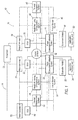
FIG. 3 is a schematic illustration of an electrical power and thermal management system, according to one example. - An exemplary gas turbine engine and schematic of an electrical system coupled thereto are described herein and are shown in the attached drawings. The electrical system includes at least two generator circuits, one coupled to a high pressure portion of a gas turbine engine and the other coupled to a low pressure portion of the gas turbine engine.
-
Figure 1 illustrates anelectrical system 10 in which a power plant orengine 12, such as a gas turbine engine, provides electrical power to afirst power circuit 14 and asecond power circuit 16. Asystem controller 18 is coupled toengine 12 and also to first andsecond circuits First power circuit 14 includes a motor/generator 20 and a General Control Unit (GCU) 22 coupled thereto. GCU 22 is also coupled to other components withinfirst power circuit 14, such as a health monitoring andprognostics system 24, athermal management system 26, and a power conversion/distribution system 28.First power circuit 14 also includes anenergy storage system 30, anexpansion module 32, and application electrical load(s) 34.System controller 18 is configured to regulate power flow (such as electrical currents and voltages within system 10) to provide power to various electrical busses. The power may be DC, AC, or conversion therebetween.System controller 18 may also be configured to execute computer program instructions to control the operation ofengine 12, including fuel flow, or the position of any variable geometry systems (e.g., from the flight control system of an aircraft or from a steering system of a ship). - Health monitoring and
prognostics system 24 is generally a unit that monitors the health of system components, and may be used to estimate component life based on sensor feedback received from components withinengine 12.Thermal management system 26 includes pumps, expansion valves, and the like, as well as a controller, to provide coolant for the purposes of climate control, and other system operations. Power conversion/distribution system 28 receives electrical power from motor/generator 20 viaGCU 22, and converts the power to a more useable form such as a DC voltage for storage inenergy storage system 30,expansion module 32, and application electrical load(s) 34. Theenergy storage system 30 may include a battery or other energy storage system.Energy storage system 30 stores energy for providing power whenengine 12 is not running (i.e., not generating power), but also to provide power to motor/generator 20 to provide starting power toengine 12 during startup.Expansion module 32 and applicationelectrical load 34 represent additional electrical components that receive power from power conversion/distribution system 28. -
Second power circuit 16 similarly includes a motor/generator 36 and aGCU 38 coupled thereto. GCU 38 is also coupled to other components withinsecond power circuit 16, such as a health monitoring andprognostics system 40, athermal management system 42, and a power conversion/distribution system 44.Second power circuit 16 also includes anenergy storage system 46, anexpansion module 48, and application electrical load(s) 50. The components 36-50 ofsecond power circuit 16 are similarly arranged as described with respect tofirst power circuit 14. Additionally, in one exampleelectrical system 10 includes one or more additional motor/generators 52 and correspondingGCUs 54 as well, which may be coupled to a gas turbine engine as will be further described. Thus, thesystem 10 is modular and flexible in that it may be expanded to include a number N of motor/generators based on contemplated operating conditions. -
Figure 2 illustrates agas turbine engine 200, which includes afan 202, a low pressure compressor and a high pressure compressor, 204 and 206, acombustor 208, and a high pressure turbine and low pressure turbine, 210 and 212, respectively. Thehigh pressure compressor 206 is connected to afirst rotor shaft 214 while thelow pressure compressor 204 is connected to asecond rotor shaft 216. The shafts extend axially and are parallel to a longitudinalcenter line axis 218.Ambient air 220 enters thefan 202 and is directed across afan rotor 222 in anannular duct 224, which in part is circumscribed byfan case 226. Bypassairflow 228 provides engine thrust while aprimary gas stream 230 is directed to acombustor 232 and thehigh pressure turbine 210. - First and
second rotor shafts second power circuits Figure 1 . Thus, first andsecond power circuits generators generators shafts -
Figure 3 illustrates an additional example of thesystem 10 ofFigure 1 . According to one example, an electrical power andthermal management system 310 may include asystem controller 318 integrally coupled to multiple systems and sub-systems, including, for instance, a thermal management system 326, 342, a power conversion anddistribution system energy storage system thermal management system 310 may be incorporated into many existing or future applications, including, but not limited to, aircraft, ship, train, and laboratory facilities. The components may perform the same and/or additional functions as those described in reference toFigure 1 . - The exemplary system as illustrated in
Figure 3 may include acontroller 318 configured to integrally manage and distribute electrical energy efficiently across thesystem 310. Thecontroller 318 may be operable to integrally control the electrical power and thermal energy associated with an individual engine, or may manage/distribute energy across a multi-engine platform. Thecontroller 318 may include any computing device configured to execute computer-readable instructions. For example, thecontroller 318 may include a processor (not shown) and a module (not shown). The processor may be integrated with, or separate from, thecontroller 318. Alternatively, thecontroller 318 may include various modules, each configured to communicate with the processor via a gateway module. Additionally or alternatively, thesystem 310 may includemultiple controllers 318, each including a processor and module. Thecontroller 318 may be configured to receive various inputs and generate and deliver various outputs in accordance with the inputs received or computer-executable instructions maintained in a database (not shown). - In general, computing systems and/or devices, such as the
controller 318 and processor may employ any number of computer operating systems. It will be apparent to those skilled in the art from the disclosure that the precise hardware and software of thecontroller 318 and processor may be any combination sufficient to carry out the functions of the examples discussed herein.Controller 318 may be configured to receive input from various sensors and sensor systems, including, but not limited to, engine performance, thermal management, fuel efficiency, electrical output, etc. Thecontroller 318 may be configured to control and manage the operation of various components of thesystem 310 in response to detected sensor input. - The
controller 318 may be in communication with the thermal management system 326, 342, which may be configured to regulate the available thermal energy efficiently across thesystem 310. Thesystem 310 may include a single, common thermal management system 326 or 342, or utilize a plurality of thermal management systems 326, 342 as illustrated inFigure 1 . The thermal management system 326, 342 may be configured to circulate coolant throughout thesystem 310. For example, the thermal management system 326, 342 may include one or more cooling systems configured to handle thermal loads of thesystem 310. A cooling fluid may be circulated through or in proximity to one ormore system 310 components to absorb heat from the said components (e.g.,generators power plant 312, power conversion/distribution system system 310. The cooling fluid may then be circulated through the system and be re-chilled for subsequent use by the thermal management system 326, 342 via a recirculation pump, for example. According to another example, fuel may be used as the appropriate heat sink to extract generated thermal energy from thesystem 310. Additionally or alternatively, thermal management system 326, 342 may be configured to circulate ambient and/or chilled air, via a refrigerant compressor, for example, throughout the system to extract heat fromsystem 310 components. Furthermore, the thermal management system 326, 342 may use coolant fluid in conjunction with ambient or chilled air to absorb heat generated fromsystem 310 components. - Additionally, the thermal management system 326, 342 may include a thermal energy storage (TES) system configured to store excess thermal energy to be maintained for later use. For example, TES may be any type of system configured to store and maintain thermal energy, e.g., gases, liquids, solids, and/or eutectic mixtures. As such, heat may be more conveniently balanced between periods of high and low performance demands.
- In the example referenced by
Figure 3 , the power conversion anddistribution systems generator distribution systems electric power bus distribution system - The power conversion and
distribution system system 310. Each converter box may be connected to signals, power, and coolant in the distribution center via a similar interface method (e.g., wires, bus bar, hoses). For instance, the power conversion anddistribution system distribution system distribution system - Additionally or alternatively, the power conversion and
distribution system system 310 to be adapted to multiple applications with minimum change. The conversion anddistribution system distribution system - The
controller 318 may likewise be in communication with theenergy storage system energy storage systems electrical power buses electrical power buses controller 318. For instance, theenergy storage systems electrical power buses energy storage systems energy storage system energy storage system energy storage system power bus controller 318. For instance, theenergy storage systems generators generators electrical power buses energy storage system electrical storage system - According to one example, the
controller 318 may be configured to interconnect multiple power sources together via a common electrical power circuit. Thecontroller 318 may operate independently from, or in conjunction with, thegenerator control units generator controller 318, via the power conversion/distribution systems power bus controller 318 may be configured to perform multi-shaft 214, 216 power sharing, whereby power may be directed to motor/generator 320 and/or 336 which provides electrical power to a shared bus network (e.g.,power bus 356 and/or 358) at the same time. In addition, thecontroller 318 may be configured to direct the motor/generators electrical power buses controller 318 may direct motor/generators distribution system generator 320 and the remaining 25% of the electrical load being supplied by motor/generator 336. Further, thecontroller 318 may be configured to adjust the load split between motor/generator electrical power buses generator generator 320 and 100-0% by motor/generator 336), yielding dynamic variable power sharing. - The
controller 318 may be in communication with thepower plant 312, operable to draw additional power in response to current load demands. For instance, thecontroller 318 may be configured to request more fuel so that the engine increases motive power supplied to motor/generators controller 18 may be configured to coordinate the output of electrical power supplied to theelectric power bus generators controller 318 may be configured to transfer power betweenrotor shafts controller 318 may manage and monitor shaft load requirements in order to conserve the useful life (e.g., reduce wear and/or stress) on theshafts engine shafts - The
controller 318 may prioritize the energy source for thermal and electrical steady state and transient demands and manage the power conversion/distribution system electrical buses controller 318 may be configured to integrally combine various electrical and thermal systems and sub-systems to manage these demands. Thecontroller 318 may coordinate the electrical power supplied by motor/generators energy storage systems controller 318 may draw power from theenergy storage system energy storage system controller 318, may absorb transient loads from theelectric power bus energy storage system power plant 312 through one or both motor/generators 320, 336 (e.g., during high thrust conditions). - Moreover, the
controller 318 may be configured to circulate coolant through thesystem 310 in response to increased operating temperatures. For example, thecontroller 318 may increase coolant supplied to one or more motor/generators controller 318 may direct the thermal management system 326, 342 to circulate coolants throughout thesystem 310 to extract heat fromsystem 310 components (e.g., power conversion/distribution system generators power plant 312,energy storage systems controller 318 may be operable to dump excess thermal loads into the appropriate heat sink(s) available and/or discharge and store excess thermal energy in the TES system incorporated within the thermal management system 326, 342. Thus, thecontroller 318 may efficiently store and extract thermal energy from the TES system based on thermal load requirements. Thecontroller 318 may likewise manage the thermal energy generated by thesystem 310 components by selectively activating and deactivating components in response to operating temperatures. For instance, thecontroller 318 may alternate activation ofrotor shaft generators controller 318 may draw power from theenergy storage system generator generator 320, 336 (e.g., to reduce the work load of motor/generator - The
controller 318 may manage the electrical loads and the distribution of power via the power conversion/distribution system controller 318 may manage the amount of electrical power supplied topower bus controller 318 may prioritize the electrical loads and power distribution demands by deactivating non-essential loads or varying electrical power distributed to low priority loads for periods of time, for instance, to meet other transient load demands. Thecontroller 318 may assign a priority level so that it is associated with a plurality of electrical loads, wherein the priority levels may be based at least in part on transient load demands and/or electrical load demands during current mission conditions. Each electrical load may be assigned a separate priority level, or multiple electrical loads may be assigned the same priority level depending on the particular application. The priority level assignment for each electrical load may be saved in thecontroller 318 such as by way of a memory (not shown) in operational communication with thecontroller 318. For instance, a priority level one (1) may be considered the highest priority, a priority level two (2) the second highest priority, and so forth. Thecontroller 318 may, for example, formulate a pulse width modulated control signal based on the assigned priority levels and transmit the signals (e.g., via electrical interfaces) to the power conversion anddistribution system - Various criteria may be used to determine the priority assignments, including but not limited to fuel efficiency parameters, transient load demands, electrical load demands depending on current mission conditions (e.g., take-off, aggressive maneuvers, acceleration, and/or other engine operations). Further, the
controller 318 may determine the transient and electrical load demands based at least partially on aircraft operational parameters. For instance, parameters such as high and low pressure turbine rotational speed, engine thrust setting, altitude, speed, atmospheric pressure, and electrical system load may be used to determine the aircraft load requirements. The parameters may be supplied to thecontroller 318 via sensor and sensor systems (not shown) in thesystem 310. The electrical power may be distributed to the electrical loads based on their priority level ranking, for example, with the electrical load assigned the highest priority receiving all of the electrical power it requires, with the remaining electrical loads receiving either reduced electrical power or no power at all. Alternatively, the available electrical power may be shared among multiple electrical loads having the highest and second highest priority level, for example. - The
controller 318 may manage the electrical power provided to thepower bus distribution system controller 318 may be configured to distinguish between essential and non-essential load demands in response to current mission conditions (e.g., take-off, certain maneuvers, acceleration, and/or other flight operations), and assign priority levels accordingly. Thecontroller 318 may continually analyze system parameters, such as current mission conditions, aircraft operational parameters, transient load requirements, and/or fuel efficiency concerns, to produce the most current priority levels for electrical load requirements. For example, thecontroller 318 may direct the power conversion/distribution system - The
controller 318 may be configured to detect, via sensors, faults occurring within the power conversion/distribution system 328, 344 (e.g., signal failures) and coordinate with supplemental converter/distribution modules to segregate and accommodate for the fault by utilizing another converter/distribution module. For instance, thecontroller 318 may utilize a converter/distribution module of the power conversion anddistribution system 344 to supply 270 V DC power topower bus 356 to meet current load demands. As such, thecontroller 318 may be configured to coordinate the various functional converter/distribution modules of the power conversion anddistribution systems - The
controller 318 may be configured to provide the platform with equipment and prognostic health monitoring information via the health monitoring and prognostics system 324, 340. Thecontroller 318 may be in communication with one or more sensors and/or sensor systems configured to monitor one ormore system 310 components. The sensors and/or sensor systems may be any type of sensor suitable for detecting/obtaining operational data from thesystem 310 components (e.g., accelerometers, position monitors, chemical gas sensors, pressure sensors, velocity sensors, magnetic sensors, humidity/moisture sensors, etc.). Thecontroller 318 may provide real-time, in flight prognostics via measuring performance metrics (e.g., temperature, voltage, current, pressure, power) to predict degrading equipment, near failure, and useful life of the equipment. For instance, thecontroller 318 may collect sensor data to analyze against historical baseline and trend comparisons maintained in the database. Thecontroller 318, via the sensors, may determine if equipment is in need of immediate or eventual service. Indeed, thecontroller 318 may be operable to coordinate the prognostic analysis with current mission objectives (e.g., high thrust conditions, certain maneuvering conditions) and, if necessary, trade component life for performance/capability. - The
intelligent controller system 310, via theintegrated controller 318, may manage energy (e.g., fuel, electrical and mechanical power, and thermal energy) efficiently across the platform. Thecontroller 318 may prioritize the energy source for thermal and electrical demands and manage the distribution system accordingly. As such, the integrated control of multiple sub-systems may achieve superior efficiency ofoverall system 310 performance. Indeed,integrated control system 310 may be readily adaptable to a wide variety of performance requirements, thereby reducing the costs of unique power systems tailored for individual applications. Additionally, theintegrated control system 310 may provide a standardized platform to insure interoperability of products/components from multiple vendors (e.g., Original Equipment Manufacturers). - Computing devices such as
system 10 generally include computer-executable instructions such as the instructions of thesystem controller 18, where the instructions may be executable by one or more computing devices such as those listed above. Computer-executable instructions may be compiled or interpreted from computer programs created using a variety of programming languages and/or technologies, including, without limitation, and either alone or in combination, Java™, C, C++, C#, Objective-C, Visual Basic, Java Script, Perl, etc. In general, a processor (e.g., a microprocessor) receives instructions, e.g., from a memory, a computer-readable medium, etc., and executes these instructions, thereby performing one or more processes, including one or more of the processes described herein. Such instructions and other data may be stored and transmitted using a variety of computer-readable media. - A computer-readable medium (also referred to as a processor-readable medium) includes any non-transitory (e.g., tangible) medium that participates in providing data (e.g., instructions) that may be read by a computer (e.g., by a processor of a computer). Such a medium may take many forms, including, but not limited to, non-volatile media and volatile media. Non-volatile media may include, for example, optical or magnetic disks and other persistent memory. Volatile media may include, for example, dynamic random access memory (DRAM), which typically constitutes a main memory. Such instructions may be transmitted by one or more transmission media, including coaxial cables, copper wire and fiber optics, including the wires that comprise a system bus coupled to a processor of a computer. Common forms of computer-readable media include, for example, a floppy disk, a flexible disk, hard disk, magnetic tape, any other magnetic medium, a CD-ROM, DVD, any other optical medium, punch cards, paper tape, any other physical medium with patterns of holes, a RAM, a PROM, an EPROM, a FLASH-EEPROM, any other memory chip or cartridge, or any other medium from which a computer can read.
- Databases, data repositories or other data stores described herein may include various kinds of mechanisms for storing, accessing, and retrieving various kinds of data, including a hierarchical database, a set of files in a file system, an application database in a proprietary format, a relational database management system (RDBMS), etc. Each such data store is generally included within a computing device employing a computer operating system such as one of those mentioned above, and are accessed via a network in any one or more of a variety of manners. A file system may be accessible from a computer operating system, and may include files stored in various formats. An RDBMS generally employs the Structured Query Language (SQL) in addition to a language for creating, storing, editing, and executing stored procedures, such as the PL/SQL language mentioned above.
- In some examples, system elements may be implemented as computer-readable instructions (e.g., software) on one or more computing devices (e.g., servers, personal computers, etc.), stored on computer readable media associated therewith (e.g., disks, memories, etc.). A computer program product may comprise such instructions stored on computer readable media for carrying out the functions described herein.
- With regard to the processes, systems, methods, heuristics, etc. described herein, it should be understood that, although the steps of such processes, etc. have been described as occurring according to a certain ordered sequence, such processes could be practiced with the described steps performed in an order other than the order described herein. It further should be understood that certain steps could be performed simultaneously, that other steps could be added, or that certain steps described herein could be omitted. In other words, the descriptions of processes herein are provided for the purpose of illustrating certain embodiments, and should in no way be construed so as to limit the claims.
- All terms used in the claims are intended to be given their broadest reasonable constructions and their ordinary meanings as understood by those knowledgeable in the technologies described herein unless an explicit indication to the contrary in made herein. In particular, use of the singular articles such as "a," "the," "said," etc. should be read to recite one or more of the indicated elements unless a claim recites an explicit limitation to the contrary.
Claims (15)
- An electrical power and thermal management system (310), comprising:a power plant (312) operable to provide motive power to an electrical generation device (320, 336);at least one conversion/distribution assembly (328, 344) configured to provide electrical power to a first electrical power bus (356, 358);a thermal management system (326, 342) configured to circulate coolant to at least one heat source; anda controller (318) in communication with the power plant (312), the electrical generation device (320, 336), the conversion/distribution assembly (328, 344), the electrical power bus (356, 358), and the thermal management system (326, 342), the controller (318) configured to integrally manage electrical and thermal steady and transient demands, wherein the controller (318) is operable to selectively distribute power to the electrical power bus (356, 358) and regulate produced thermal energy in response to electrical and thermal demands, respectively.
- The system as claimed in claim 1, wherein the controller (318) is configured to receive operational parameters representative of electrical load demands and manage the electrical loads in response to the operational parameters.
- The system as claimed in claims 1 or 2, wherein the controller (318) is configured to assign a priority level so that it is associated with a plurality of electrical loads and formulate a pulse width modulated control signal based on the assigned priority levels, the controller (318) operable to transmit the control signal to the conversion/distribution assembly (328, 344) for controlling the distribution of electrical power.
- The system as claimed in claims 2 or 3, wherein the controller (318) is configured to assign the priority levels based on at least one of transient load demands and electrical load demands responsive to operational parameters.
- The system as claimed in claims 3 or 4, wherein the controller (318) is configured to suppress electrical power distributed to the electrical load assigned with a lowest priority to meet higher priority demands.
- The system as claimed in any one of the claims 3 to 5, wherein the controller (318) is operable to control the amount of electrical power supplied to the first electrical power bus (356, 358) and selectively distribute electrical power to the electrical power bus (356, 358) via the conversion/distribution assembly (328, 344) in response to the load demands.
- The system as claimed in any one of the claims 1 to 6, further comprising an energy storage system (330, 346) configured to absorb transient loads and selectively supply electrical power for electrical transients at the direction of the controller (318).
- The system as claimed in any one of the claims 1 to 7, wherein the controller (318) is configured to manage the thermal energy generated by at least one heat source via at least one of:temporarily reduce electrical power distributed to the heat source to reduce heat produced from the heat source;increase coolant, via the thermal management system (326, 342), in response to increased temperature to extract heat; andsupply heat to and extract heat from the thermal management system (326, 342) in response to excess and deficient thermal energy, respectively.
- The system as claimed in any one of the claims 1 to 8, further comprising a second electrical generation device (336) in communication with the controller (318) and the conversion/distribution assembly (328, 344), wherein the conversion/distribution assembly (328, 344) is configured for variable power sharing between the first generation device (320) and second electrical generation device (336) to supply electrical power to a common electrical load at the direction of the controller (318).
- The system as claimed in any of the claims 1 to 9, wherein the controller (318) is configured to increase output of the power plant (312) to generate additional electrical power, via the electrical generation device (320, 336), to supply to the electrical power bus (356, 358), via the conversion/distribution assembly (328, 344), to meet electrical load demands.
- A turbine engine (200), comprising:a compressor (204, 206) having a mid-compression station and an exit pressure station;a low pressure turbine (212) and a high pressure turbine (210);an electrical system (310) configured to supply power in parallel to a first electrical bus (356) and a second electrical bus (358), the electrical system including:a first electrical generation device (320) coupled to the low pressure turbine (212);a first conversion/distribution assembly (328) coupled to the first electrical generation device (320) operable to supply electrical power to the first electrical power bus (356);a second electrical generation device (336) coupled to the high pressure turbine (210);a second conversion/distribution assembly (344) coupled to the second electrical generation device (336) operable to supply electrical power to a second electrical power bus (358);a thermal management system (326, 342) configured to circulate coolant to at least one heat source;an energy storage system (330, 346) configured to supply power to and absorb power from the first power bus (356) and the second power bus (358);a controller (318) configured to control operation of the turbine engine (200); anda non-transitory computer readable medium, having instructions tangibly embodied thereon, the instructions being executable by a processor to instruct the controller to:coordinate the electrical power supplied by the first generation device (320), second generation device (336), and energy storage system (330, 336) to the first power bus (356) and the second power bus (358);manage the amount of electrical power supplied to the first power bus (356) and the second power bus (358) in response to electrical load demands; anddirect the thermal management system (326, 342) to extract heat from the at least one heat source.
- The turbine engine as claimed in claim 11, wherein the computer readable medium is configured to assign a priority level so that it is associated with a plurality of electrical loads and formulate a pulse width modulated control signal based on the assigned priority levels, the controller (318) operable to transmit the control signal to the first conversion/distribution assembly (328) and/or the second conversion/distribution assembly (344) for controlling the distribution of electrical power, wherein the priority levels are assigned based on at least one of transient load demands and operation parameters representative of electrical load demands.
- The turbine engine as claimed in claim 12, wherein the first conversion/distribution assembly (328) and/or the second conversion/distribution assembly (344) is operable, via the computer readable medium, to suppress electrical power distributed to the electrical load assigned with a lowest priority to meet higher priority demands.
- The turbine engine as claimed in any one of the claims 11 to 13, wherein the computer readable medium is configured to selectively supply electrical power from the energy storage system (330, 346) for electrical transients and direct the energy storage system (330, 346) to absorb electrical transients from at least one of the first power bus (356) and the second power bus (358).
- The turbine engine as claimed in any one of the claims 11 to 14, wherein the computer readable medium is operable to manage the power output of the turbine engine (200), wherein the computer readable medium instructs the controller (318) to transfer power between the low pressure turbine (212) and the high pressure turbine (210), and increase electrical power supplied by at least one of the first electrical generation device (320) and the second electrical generation device (336) via increasing the output of at least one of the low pressure turbine (212) and high pressure turbine (210), respectively.
Applications Claiming Priority (1)
| Application Number | Priority Date | Filing Date | Title |
|---|---|---|---|
| US201361912962P | 2013-12-06 | 2013-12-06 |
Publications (2)
| Publication Number | Publication Date |
|---|---|
| EP2881563A1 true EP2881563A1 (en) | 2015-06-10 |
| EP2881563B1 EP2881563B1 (en) | 2020-01-15 |
Family
ID=52144376
Family Applications (1)
| Application Number | Title | Priority Date | Filing Date |
|---|---|---|---|
| EP14195426.3A Active EP2881563B1 (en) | 2013-12-06 | 2014-11-28 | Integrated electrical power and thermal management system |
Country Status (2)
| Country | Link |
|---|---|
| US (1) | US9366182B2 (en) |
| EP (1) | EP2881563B1 (en) |
Cited By (7)
| Publication number | Priority date | Publication date | Assignee | Title |
|---|---|---|---|---|
| EP3418202A1 (en) * | 2017-06-22 | 2018-12-26 | Airbus Helicopters | Electrical distribution housing incorporating disconnection, discharge and conversion functions for an aircraft |
| EP3502444A1 (en) * | 2017-12-20 | 2019-06-26 | Rolls-Royce plc | Methods and apparatus for controlling electrical power supplied to a component of a vehicle |
| US10583931B2 (en) | 2013-12-30 | 2020-03-10 | Rolls-Royce North American Technologies, Inc. | System and method for coordinated control of a power system |
| EP4223998A1 (en) * | 2022-02-02 | 2023-08-09 | Rolls-Royce plc | Combination of a gas turbine engine and a power electronics |
| US11946417B2 (en) | 2022-02-02 | 2024-04-02 | Rolls-Royce Plc | Combination of a gas turbine engine and a power electronics |
| US20240352872A1 (en) * | 2023-04-20 | 2024-10-24 | Rolls-Royce North American Technologies, Inc. | Thermal energy system to minimize or eliminate rotor bow |
| US12421905B2 (en) | 2023-04-20 | 2025-09-23 | Rolls-Royce North American Technologies, Inc. | Thermal energy system to minimize or eliminate rotor bow |
Families Citing this family (30)
| Publication number | Priority date | Publication date | Assignee | Title |
|---|---|---|---|---|
| WO2012135314A1 (en) * | 2011-03-29 | 2012-10-04 | Rolls-Royce North American Technologies Inc. | Vehicle system |
| US10000293B2 (en) | 2015-01-23 | 2018-06-19 | General Electric Company | Gas-electric propulsion system for an aircraft |
| US9938853B2 (en) | 2015-10-23 | 2018-04-10 | General Electric Company | Torsional damping for gas turbine engines |
| GB2547946B (en) | 2016-03-04 | 2020-05-20 | Ge Aviat Systems Ltd | Method and apparatus for modular power distribution |
| US9764848B1 (en) | 2016-03-07 | 2017-09-19 | General Electric Company | Propulsion system for an aircraft |
| US10308366B2 (en) | 2016-08-22 | 2019-06-04 | General Electric Company | Embedded electric machine |
| US10071811B2 (en) * | 2016-08-22 | 2018-09-11 | General Electric Company | Embedded electric machine |
| US10093428B2 (en) * | 2016-08-22 | 2018-10-09 | General Electric Company | Electric propulsion system |
| US10487839B2 (en) | 2016-08-22 | 2019-11-26 | General Electric Company | Embedded electric machine |
| US11149578B2 (en) | 2017-02-10 | 2021-10-19 | General Electric Company | Propulsion system for an aircraft |
| US10822103B2 (en) | 2017-02-10 | 2020-11-03 | General Electric Company | Propulsor assembly for an aircraft |
| US10793281B2 (en) | 2017-02-10 | 2020-10-06 | General Electric Company | Propulsion system for an aircraft |
| US10762726B2 (en) | 2017-06-13 | 2020-09-01 | General Electric Company | Hybrid-electric propulsion system for an aircraft |
| US10823078B2 (en) | 2017-06-28 | 2020-11-03 | General Electric Company | Systems and methods for starting a turbine engine |
| US10951095B2 (en) | 2018-08-01 | 2021-03-16 | General Electric Company | Electric machine arc path protection |
| US11332256B2 (en) | 2018-08-21 | 2022-05-17 | General Electric Company | Fault tolerant hybrid electric propulsion system for an aerial vehicle |
| US11015480B2 (en) | 2018-08-21 | 2021-05-25 | General Electric Company | Feed forward load sensing for hybrid electric systems |
| US11156128B2 (en) | 2018-08-22 | 2021-10-26 | General Electric Company | Embedded electric machine |
| US11097849B2 (en) | 2018-09-10 | 2021-08-24 | General Electric Company | Aircraft having an aft engine |
| US11027719B2 (en) | 2018-12-03 | 2021-06-08 | General Electric Company | Distributed power generation for a vehicle system |
| GB2584696A (en) * | 2019-06-12 | 2020-12-16 | Rolls Royce Plc | Generating electrical power at high thrust conditions |
| US11539316B2 (en) | 2019-07-30 | 2022-12-27 | General Electric Company | Active stability control of compression systems utilizing electric machines |
| GB201916566D0 (en) * | 2019-11-14 | 2020-01-01 | Rolls Royce Plc | Aircraft power generation system |
| US12421892B2 (en) * | 2019-12-04 | 2025-09-23 | Rolls-Royce North American Technologies Inc. | Hybrid turbine engine with selective electrical module engagement |
| US12021377B2 (en) * | 2020-06-23 | 2024-06-25 | The Boeing Company | Power management system |
| US12149154B2 (en) | 2021-07-22 | 2024-11-19 | General Electric Company | Electric machine having a hybrid insulative-conductive manifold |
| FR3129375B1 (en) * | 2021-11-25 | 2026-01-30 | Safran | ELECTRICAL POWER CONVERSION AND TRANSPORT SYSTEM FOR THE INTERNAL HYBRIDIZATION OF AN AIRCRAFT TURBOMACHINE |
| US20240300657A1 (en) * | 2023-03-06 | 2024-09-12 | Raytheon Technologies Corporation | Aircraft hybrid electric propulsion architecture enabling modes of operation |
| US20240327011A1 (en) * | 2023-03-27 | 2024-10-03 | Northrop Grumman Systems Corporation | Adaptive aircraft power management system |
| US20250330026A1 (en) * | 2024-04-19 | 2025-10-23 | Kevin R. Williams | Variable load continuously synchronized engine/generators with energy storage for large and dynamic loads |
Citations (3)
| Publication number | Priority date | Publication date | Assignee | Title |
|---|---|---|---|---|
| US20120247117A1 (en) * | 2011-03-29 | 2012-10-04 | Steven Gagne | Vehicle system |
| US20120248242A1 (en) * | 2011-03-28 | 2012-10-04 | Steven Gagne | Aircraft and airborne electrical power and thermal management system |
| US20130111917A1 (en) * | 2011-11-03 | 2013-05-09 | Northrop Grumman Systems Corporation | Apparatus for aircraft with high peak power equipment |
Family Cites Families (20)
| Publication number | Priority date | Publication date | Assignee | Title |
|---|---|---|---|---|
| US4510756A (en) * | 1981-11-20 | 1985-04-16 | Consolidated Natural Gas Service Company, Inc. | Cogeneration |
| US4752697A (en) * | 1987-04-10 | 1988-06-21 | International Cogeneration Corporation | Cogeneration system and method |
| GB8907788D0 (en) | 1989-04-06 | 1989-05-17 | Rolls Royce Plc | Management of heat generated by aircraft gas turbine installations |
| US5536976A (en) * | 1994-03-03 | 1996-07-16 | Gas Research Institute | Multiple service load solid state switching for controlled cogeneration system |
| US5731688A (en) * | 1996-03-13 | 1998-03-24 | Alaska Power Systems Inc. | Control system and circuits for distributed electrical-power generating stations |
| US5734255A (en) * | 1996-03-13 | 1998-03-31 | Alaska Power Systems Inc. | Control system and circuits for distributed electrical power generating stations |
| GB9606546D0 (en) | 1996-03-28 | 1996-06-05 | Rolls Royce Plc | Gas turbine engine system |
| US6380639B1 (en) | 2000-05-11 | 2002-04-30 | Bombardier Inc. | System, method and apparatus for power regulation |
| US6906432B2 (en) | 2003-07-02 | 2005-06-14 | Mes International, Inc. | Electrical power generation system and method |
| US6931856B2 (en) | 2003-09-12 | 2005-08-23 | Mes International, Inc. | Multi-spool turbogenerator system and control method |
| US7285871B2 (en) | 2004-08-25 | 2007-10-23 | Honeywell International, Inc. | Engine power extraction control system |
| US8099198B2 (en) * | 2005-07-25 | 2012-01-17 | Echogen Power Systems, Inc. | Hybrid power generation and energy storage system |
| US7468561B2 (en) | 2007-03-27 | 2008-12-23 | General Electric Company | Integrated electrical power extraction for aircraft engines |
| US7936086B2 (en) | 2008-03-06 | 2011-05-03 | Honeywell International, Inc. | Paralleled HVDC bus electrical power system architecture |
| US8286432B2 (en) | 2008-11-25 | 2012-10-16 | Honeywell International Inc. | Electric power generating turbine engine fuel supply system |
| US8039983B2 (en) | 2008-12-02 | 2011-10-18 | The Boeing Company | Systems and methods for providing AC power from multiple turbine engine spools |
| US8164208B2 (en) | 2009-04-15 | 2012-04-24 | General Electric Company | Systems involving multi-spool generators and variable speed electrical generators |
| US8395274B2 (en) * | 2009-04-15 | 2013-03-12 | Hamilton Sundstrand Corporation | Integrated power unit as energy storage device for electrical power system |
| US10060296B2 (en) * | 2012-11-15 | 2018-08-28 | Kevin Lee Friesth | Quintuple-effect generation multi-cycle hybrid renewable energy system with integrated energy provisioning, storage facilities and amalgamated control system cross-reference to related applications |
| CA2905233C (en) * | 2013-03-14 | 2022-04-26 | Rolls-Royce Corporation | Intelligent integrated control system and method |
-
2014
- 2014-11-18 US US14/546,622 patent/US9366182B2/en active Active
- 2014-11-28 EP EP14195426.3A patent/EP2881563B1/en active Active
Patent Citations (3)
| Publication number | Priority date | Publication date | Assignee | Title |
|---|---|---|---|---|
| US20120248242A1 (en) * | 2011-03-28 | 2012-10-04 | Steven Gagne | Aircraft and airborne electrical power and thermal management system |
| US20120247117A1 (en) * | 2011-03-29 | 2012-10-04 | Steven Gagne | Vehicle system |
| US20130111917A1 (en) * | 2011-11-03 | 2013-05-09 | Northrop Grumman Systems Corporation | Apparatus for aircraft with high peak power equipment |
Cited By (11)
| Publication number | Priority date | Publication date | Assignee | Title |
|---|---|---|---|---|
| US10583931B2 (en) | 2013-12-30 | 2020-03-10 | Rolls-Royce North American Technologies, Inc. | System and method for coordinated control of a power system |
| EP2889452B1 (en) * | 2013-12-30 | 2020-07-22 | Rolls-Royce Corporation | System and method for coordinated control of a power system |
| EP3418202A1 (en) * | 2017-06-22 | 2018-12-26 | Airbus Helicopters | Electrical distribution housing incorporating disconnection, discharge and conversion functions for an aircraft |
| EP3502444A1 (en) * | 2017-12-20 | 2019-06-26 | Rolls-Royce plc | Methods and apparatus for controlling electrical power supplied to a component of a vehicle |
| US11015525B2 (en) | 2017-12-20 | 2021-05-25 | Rolls-Royce Plc | Methods, computer programs, non transitory computer readable storage mediums, signals, and apparatus for controlling electrical power supplied to a component of a vehicle |
| EP4223998A1 (en) * | 2022-02-02 | 2023-08-09 | Rolls-Royce plc | Combination of a gas turbine engine and a power electronics |
| US11946417B2 (en) | 2022-02-02 | 2024-04-02 | Rolls-Royce Plc | Combination of a gas turbine engine and a power electronics |
| US12392288B2 (en) | 2022-02-02 | 2025-08-19 | Rolls-Royce Plc | Combination of a gas turbine engine and a power electronics |
| US20240352872A1 (en) * | 2023-04-20 | 2024-10-24 | Rolls-Royce North American Technologies, Inc. | Thermal energy system to minimize or eliminate rotor bow |
| US12234741B2 (en) * | 2023-04-20 | 2025-02-25 | Rolls-Royce North American Technologies, Inc. | Thermal energy system to minimize or eliminate rotor bow |
| US12421905B2 (en) | 2023-04-20 | 2025-09-23 | Rolls-Royce North American Technologies, Inc. | Thermal energy system to minimize or eliminate rotor bow |
Also Published As
| Publication number | Publication date |
|---|---|
| US9366182B2 (en) | 2016-06-14 |
| EP2881563B1 (en) | 2020-01-15 |
| US20150159552A1 (en) | 2015-06-11 |
Similar Documents
| Publication | Publication Date | Title |
|---|---|---|
| EP2881563B1 (en) | Integrated electrical power and thermal management system | |
| US9386730B2 (en) | Modular power electronics distribution system | |
| EP2930335B1 (en) | Fuel-air ratio control of gas turbine engines | |
| US9790864B2 (en) | Prognostic health management approaches for propulsion control system | |
| CA2905233C (en) | Intelligent integrated control system and method | |
| EP2990626B1 (en) | Operation of aircraft engines during transient conditions | |
| EP3118925B1 (en) | Thermal management of energy storage | |
| EP2887536B1 (en) | Control system for a dual redundant motor/generator and engine | |
| EP2937519B1 (en) | Method to control electric starter generator for gas turbine engines | |
| WO2014150491A2 (en) | Prognostic health management approaches for propulsion control systems | |
| US20240343399A1 (en) | Overall aircraft system data collector for prognostics and health management | |
| EP2969755B1 (en) | Propulsion, electrical, and thermal management device for a small unmanned aerial vehicle | |
| CA2758211C (en) | Aircraft comprising a reversible rotary electrical machine | |
| EP4428038A1 (en) | Aircraft hybrid electric propulsion architecture enabling modes of operation | |
| EP2889467B1 (en) | Fuel flow splitter and gas turbine fuel system health monitoring | |
| SE520837C2 (en) | Power distribution system and method for controlling power | |
| EP4497688A2 (en) | Aircraft hybrid electric propulsion and attitude controller | |
| US12595071B1 (en) | Parallel hybrid electric vertical takeoff and landing aircraft | |
| EP4607740A1 (en) | Aeronautical power system | |
| Markov et al. | Analysis of a hybrid partial turboelectric distributed propulsion system for a medium altitude long endurance uav | |
| Nick Carter III et al. | A Subsystem Integration Technology Concept | |
| Vratny et al. | DESIGN AND OFF-DESIGN PERFORMANCE OF ELECTRIC SYSTEM ARCHITECTURES FOR ELECTRIC POWERED AIRCRAFT | |
| Carter III et al. | A Subsystem Integration Technology Concept |
Legal Events
| Date | Code | Title | Description |
|---|---|---|---|
| PUAI | Public reference made under article 153(3) epc to a published international application that has entered the european phase |
Free format text: ORIGINAL CODE: 0009012 |
|
| 17P | Request for examination filed |
Effective date: 20141128 |
|
| AK | Designated contracting states |
Kind code of ref document: A1 Designated state(s): AL AT BE BG CH CY CZ DE DK EE ES FI FR GB GR HR HU IE IS IT LI LT LU LV MC MK MT NL NO PL PT RO RS SE SI SK SM TR |
|
| AX | Request for extension of the european patent |
Extension state: BA ME |
|
| R17P | Request for examination filed (corrected) |
Effective date: 20151202 |
|
| RBV | Designated contracting states (corrected) |
Designated state(s): AL AT BE BG CH CY CZ DE DK EE ES FI FR GB GR HR HU IE IS IT LI LT LU LV MC MK MT NL NO PL PT RO RS SE SI SK SM TR |
|
| GRAP | Despatch of communication of intention to grant a patent |
Free format text: ORIGINAL CODE: EPIDOSNIGR1 |
|
| STAA | Information on the status of an ep patent application or granted ep patent |
Free format text: STATUS: GRANT OF PATENT IS INTENDED |
|
| INTG | Intention to grant announced |
Effective date: 20190906 |
|
| GRAS | Grant fee paid |
Free format text: ORIGINAL CODE: EPIDOSNIGR3 |
|
| GRAA | (expected) grant |
Free format text: ORIGINAL CODE: 0009210 |
|
| STAA | Information on the status of an ep patent application or granted ep patent |
Free format text: STATUS: THE PATENT HAS BEEN GRANTED |
|
| AK | Designated contracting states |
Kind code of ref document: B1 Designated state(s): AL AT BE BG CH CY CZ DE DK EE ES FI FR GB GR HR HU IE IS IT LI LT LU LV MC MK MT NL NO PL PT RO RS SE SI SK SM TR |
|
| REG | Reference to a national code |
Ref country code: GB Ref legal event code: FG4D Ref country code: CH Ref legal event code: EP |
|
| REG | Reference to a national code |
Ref country code: IE Ref legal event code: FG4D |
|
| REG | Reference to a national code |
Ref country code: DE Ref legal event code: R096 Ref document number: 602014060002 Country of ref document: DE |
|
| REG | Reference to a national code |
Ref country code: AT Ref legal event code: REF Ref document number: 1225344 Country of ref document: AT Kind code of ref document: T Effective date: 20200215 |
|
| REG | Reference to a national code |
Ref country code: NL Ref legal event code: MP Effective date: 20200115 |
|
| REG | Reference to a national code |
Ref country code: LT Ref legal event code: MG4D |
|
| PG25 | Lapsed in a contracting state [announced via postgrant information from national office to epo] |
Ref country code: PT Free format text: LAPSE BECAUSE OF FAILURE TO SUBMIT A TRANSLATION OF THE DESCRIPTION OR TO PAY THE FEE WITHIN THE PRESCRIBED TIME-LIMIT Effective date: 20200607 Ref country code: RS Free format text: LAPSE BECAUSE OF FAILURE TO SUBMIT A TRANSLATION OF THE DESCRIPTION OR TO PAY THE FEE WITHIN THE PRESCRIBED TIME-LIMIT Effective date: 20200115 Ref country code: NL Free format text: LAPSE BECAUSE OF FAILURE TO SUBMIT A TRANSLATION OF THE DESCRIPTION OR TO PAY THE FEE WITHIN THE PRESCRIBED TIME-LIMIT Effective date: 20200115 Ref country code: NO Free format text: LAPSE BECAUSE OF FAILURE TO SUBMIT A TRANSLATION OF THE DESCRIPTION OR TO PAY THE FEE WITHIN THE PRESCRIBED TIME-LIMIT Effective date: 20200415 Ref country code: FI Free format text: LAPSE BECAUSE OF FAILURE TO SUBMIT A TRANSLATION OF THE DESCRIPTION OR TO PAY THE FEE WITHIN THE PRESCRIBED TIME-LIMIT Effective date: 20200115 |
|
| PG25 | Lapsed in a contracting state [announced via postgrant information from national office to epo] |
Ref country code: IS Free format text: LAPSE BECAUSE OF FAILURE TO SUBMIT A TRANSLATION OF THE DESCRIPTION OR TO PAY THE FEE WITHIN THE PRESCRIBED TIME-LIMIT Effective date: 20200515 Ref country code: SE Free format text: LAPSE BECAUSE OF FAILURE TO SUBMIT A TRANSLATION OF THE DESCRIPTION OR TO PAY THE FEE WITHIN THE PRESCRIBED TIME-LIMIT Effective date: 20200115 Ref country code: LV Free format text: LAPSE BECAUSE OF FAILURE TO SUBMIT A TRANSLATION OF THE DESCRIPTION OR TO PAY THE FEE WITHIN THE PRESCRIBED TIME-LIMIT Effective date: 20200115 Ref country code: HR Free format text: LAPSE BECAUSE OF FAILURE TO SUBMIT A TRANSLATION OF THE DESCRIPTION OR TO PAY THE FEE WITHIN THE PRESCRIBED TIME-LIMIT Effective date: 20200115 Ref country code: BG Free format text: LAPSE BECAUSE OF FAILURE TO SUBMIT A TRANSLATION OF THE DESCRIPTION OR TO PAY THE FEE WITHIN THE PRESCRIBED TIME-LIMIT Effective date: 20200415 Ref country code: GR Free format text: LAPSE BECAUSE OF FAILURE TO SUBMIT A TRANSLATION OF THE DESCRIPTION OR TO PAY THE FEE WITHIN THE PRESCRIBED TIME-LIMIT Effective date: 20200416 |
|
| REG | Reference to a national code |
Ref country code: DE Ref legal event code: R097 Ref document number: 602014060002 Country of ref document: DE |
|
| PG25 | Lapsed in a contracting state [announced via postgrant information from national office to epo] |
Ref country code: RO Free format text: LAPSE BECAUSE OF FAILURE TO SUBMIT A TRANSLATION OF THE DESCRIPTION OR TO PAY THE FEE WITHIN THE PRESCRIBED TIME-LIMIT Effective date: 20200115 Ref country code: SK Free format text: LAPSE BECAUSE OF FAILURE TO SUBMIT A TRANSLATION OF THE DESCRIPTION OR TO PAY THE FEE WITHIN THE PRESCRIBED TIME-LIMIT Effective date: 20200115 Ref country code: SM Free format text: LAPSE BECAUSE OF FAILURE TO SUBMIT A TRANSLATION OF THE DESCRIPTION OR TO PAY THE FEE WITHIN THE PRESCRIBED TIME-LIMIT Effective date: 20200115 Ref country code: LT Free format text: LAPSE BECAUSE OF FAILURE TO SUBMIT A TRANSLATION OF THE DESCRIPTION OR TO PAY THE FEE WITHIN THE PRESCRIBED TIME-LIMIT Effective date: 20200115 Ref country code: CZ Free format text: LAPSE BECAUSE OF FAILURE TO SUBMIT A TRANSLATION OF THE DESCRIPTION OR TO PAY THE FEE WITHIN THE PRESCRIBED TIME-LIMIT Effective date: 20200115 Ref country code: ES Free format text: LAPSE BECAUSE OF FAILURE TO SUBMIT A TRANSLATION OF THE DESCRIPTION OR TO PAY THE FEE WITHIN THE PRESCRIBED TIME-LIMIT Effective date: 20200115 Ref country code: EE Free format text: LAPSE BECAUSE OF FAILURE TO SUBMIT A TRANSLATION OF THE DESCRIPTION OR TO PAY THE FEE WITHIN THE PRESCRIBED TIME-LIMIT Effective date: 20200115 Ref country code: DK Free format text: LAPSE BECAUSE OF FAILURE TO SUBMIT A TRANSLATION OF THE DESCRIPTION OR TO PAY THE FEE WITHIN THE PRESCRIBED TIME-LIMIT Effective date: 20200115 |
|
| REG | Reference to a national code |
Ref country code: AT Ref legal event code: MK05 Ref document number: 1225344 Country of ref document: AT Kind code of ref document: T Effective date: 20200115 |
|
| PLBE | No opposition filed within time limit |
Free format text: ORIGINAL CODE: 0009261 |
|
| STAA | Information on the status of an ep patent application or granted ep patent |
Free format text: STATUS: NO OPPOSITION FILED WITHIN TIME LIMIT |
|
| 26N | No opposition filed |
Effective date: 20201016 |
|
| PG25 | Lapsed in a contracting state [announced via postgrant information from national office to epo] |
Ref country code: IT Free format text: LAPSE BECAUSE OF FAILURE TO SUBMIT A TRANSLATION OF THE DESCRIPTION OR TO PAY THE FEE WITHIN THE PRESCRIBED TIME-LIMIT Effective date: 20200115 Ref country code: AT Free format text: LAPSE BECAUSE OF FAILURE TO SUBMIT A TRANSLATION OF THE DESCRIPTION OR TO PAY THE FEE WITHIN THE PRESCRIBED TIME-LIMIT Effective date: 20200115 |
|
| PG25 | Lapsed in a contracting state [announced via postgrant information from national office to epo] |
Ref country code: SI Free format text: LAPSE BECAUSE OF FAILURE TO SUBMIT A TRANSLATION OF THE DESCRIPTION OR TO PAY THE FEE WITHIN THE PRESCRIBED TIME-LIMIT Effective date: 20200115 Ref country code: PL Free format text: LAPSE BECAUSE OF FAILURE TO SUBMIT A TRANSLATION OF THE DESCRIPTION OR TO PAY THE FEE WITHIN THE PRESCRIBED TIME-LIMIT Effective date: 20200115 |
|
| PG25 | Lapsed in a contracting state [announced via postgrant information from national office to epo] |
Ref country code: MC Free format text: LAPSE BECAUSE OF FAILURE TO SUBMIT A TRANSLATION OF THE DESCRIPTION OR TO PAY THE FEE WITHIN THE PRESCRIBED TIME-LIMIT Effective date: 20200115 |
|
| REG | Reference to a national code |
Ref country code: CH Ref legal event code: PL |
|
| GBPC | Gb: european patent ceased through non-payment of renewal fee |
Effective date: 20201128 |
|
| PG25 | Lapsed in a contracting state [announced via postgrant information from national office to epo] |
Ref country code: LU Free format text: LAPSE BECAUSE OF NON-PAYMENT OF DUE FEES Effective date: 20201128 |
|
| REG | Reference to a national code |
Ref country code: BE Ref legal event code: MM Effective date: 20201130 |
|
| PG25 | Lapsed in a contracting state [announced via postgrant information from national office to epo] |
Ref country code: LI Free format text: LAPSE BECAUSE OF NON-PAYMENT OF DUE FEES Effective date: 20201130 Ref country code: CH Free format text: LAPSE BECAUSE OF NON-PAYMENT OF DUE FEES Effective date: 20201130 |
|
| PG25 | Lapsed in a contracting state [announced via postgrant information from national office to epo] |
Ref country code: FR Free format text: LAPSE BECAUSE OF NON-PAYMENT OF DUE FEES Effective date: 20201130 Ref country code: IE Free format text: LAPSE BECAUSE OF NON-PAYMENT OF DUE FEES Effective date: 20201128 |
|
| PG25 | Lapsed in a contracting state [announced via postgrant information from national office to epo] |
Ref country code: GB Free format text: LAPSE BECAUSE OF NON-PAYMENT OF DUE FEES Effective date: 20201128 |
|
| PG25 | Lapsed in a contracting state [announced via postgrant information from national office to epo] |
Ref country code: TR Free format text: LAPSE BECAUSE OF FAILURE TO SUBMIT A TRANSLATION OF THE DESCRIPTION OR TO PAY THE FEE WITHIN THE PRESCRIBED TIME-LIMIT Effective date: 20200115 Ref country code: MT Free format text: LAPSE BECAUSE OF FAILURE TO SUBMIT A TRANSLATION OF THE DESCRIPTION OR TO PAY THE FEE WITHIN THE PRESCRIBED TIME-LIMIT Effective date: 20200115 Ref country code: CY Free format text: LAPSE BECAUSE OF FAILURE TO SUBMIT A TRANSLATION OF THE DESCRIPTION OR TO PAY THE FEE WITHIN THE PRESCRIBED TIME-LIMIT Effective date: 20200115 |
|
| PG25 | Lapsed in a contracting state [announced via postgrant information from national office to epo] |
Ref country code: MK Free format text: LAPSE BECAUSE OF FAILURE TO SUBMIT A TRANSLATION OF THE DESCRIPTION OR TO PAY THE FEE WITHIN THE PRESCRIBED TIME-LIMIT Effective date: 20200115 Ref country code: AL Free format text: LAPSE BECAUSE OF FAILURE TO SUBMIT A TRANSLATION OF THE DESCRIPTION OR TO PAY THE FEE WITHIN THE PRESCRIBED TIME-LIMIT Effective date: 20200115 |
|
| PG25 | Lapsed in a contracting state [announced via postgrant information from national office to epo] |
Ref country code: BE Free format text: LAPSE BECAUSE OF NON-PAYMENT OF DUE FEES Effective date: 20201130 |
|
| P01 | Opt-out of the competence of the unified patent court (upc) registered |
Effective date: 20230528 |
|
| PGFP | Annual fee paid to national office [announced via postgrant information from national office to epo] |
Ref country code: DE Payment date: 20251126 Year of fee payment: 12 |