EP2881536A2 - Burst sleeve and positive indication for fracture sleeve opening - Google Patents
Burst sleeve and positive indication for fracture sleeve opening Download PDFInfo
- Publication number
- EP2881536A2 EP2881536A2 EP14196403.1A EP14196403A EP2881536A2 EP 2881536 A2 EP2881536 A2 EP 2881536A2 EP 14196403 A EP14196403 A EP 14196403A EP 2881536 A2 EP2881536 A2 EP 2881536A2
- Authority
- EP
- European Patent Office
- Prior art keywords
- insert
- pressure
- downhole tool
- fluid pressure
- burst
- Prior art date
- Legal status (The legal status is an assumption and is not a legal conclusion. Google has not performed a legal analysis and makes no representation as to the accuracy of the status listed.)
- Granted
Links
- 239000012530 fluid Substances 0.000 claims abstract description 61
- 230000004044 response Effects 0.000 claims abstract description 32
- 238000000034 method Methods 0.000 claims description 11
- 230000009172 bursting Effects 0.000 claims description 6
- 229910001018 Cast iron Inorganic materials 0.000 claims description 5
- 238000010008 shearing Methods 0.000 claims description 4
- 238000007789 sealing Methods 0.000 claims description 3
- 230000008878 coupling Effects 0.000 claims description 2
- 238000010168 coupling process Methods 0.000 claims description 2
- 238000005859 coupling reaction Methods 0.000 claims description 2
- 238000012360 testing method Methods 0.000 description 15
- 230000001681 protective effect Effects 0.000 description 8
- 230000015572 biosynthetic process Effects 0.000 description 5
- 239000000463 material Substances 0.000 description 5
- 230000008901 benefit Effects 0.000 description 4
- 238000002955 isolation Methods 0.000 description 4
- 239000002131 composite material Substances 0.000 description 3
- 239000004519 grease Substances 0.000 description 2
- 239000007769 metal material Substances 0.000 description 2
- 238000003801 milling Methods 0.000 description 2
- 229910000838 Al alloy Inorganic materials 0.000 description 1
- 230000004075 alteration Effects 0.000 description 1
- 229910052782 aluminium Inorganic materials 0.000 description 1
- XAGFODPZIPBFFR-UHFFFAOYSA-N aluminium Chemical compound [Al] XAGFODPZIPBFFR-UHFFFAOYSA-N 0.000 description 1
- 238000009530 blood pressure measurement Methods 0.000 description 1
- 239000004568 cement Substances 0.000 description 1
- 238000012790 confirmation Methods 0.000 description 1
- 238000012937 correction Methods 0.000 description 1
- 230000009977 dual effect Effects 0.000 description 1
- 230000000694 effects Effects 0.000 description 1
- 239000000945 filler Substances 0.000 description 1
- 238000007373 indentation Methods 0.000 description 1
- 229910052751 metal Inorganic materials 0.000 description 1
- 239000002184 metal Substances 0.000 description 1
- 150000002739 metals Chemical class 0.000 description 1
- 238000012986 modification Methods 0.000 description 1
- 230000004048 modification Effects 0.000 description 1
- 230000003245 working effect Effects 0.000 description 1
Images



Classifications
-
- E—FIXED CONSTRUCTIONS
- E21—EARTH OR ROCK DRILLING; MINING
- E21B—EARTH OR ROCK DRILLING; OBTAINING OIL, GAS, WATER, SOLUBLE OR MELTABLE MATERIALS OR A SLURRY OF MINERALS FROM WELLS
- E21B34/00—Valve arrangements for boreholes or wells
- E21B34/06—Valve arrangements for boreholes or wells in wells
-
- E—FIXED CONSTRUCTIONS
- E21—EARTH OR ROCK DRILLING; MINING
- E21B—EARTH OR ROCK DRILLING; OBTAINING OIL, GAS, WATER, SOLUBLE OR MELTABLE MATERIALS OR A SLURRY OF MINERALS FROM WELLS
- E21B34/00—Valve arrangements for boreholes or wells
- E21B34/06—Valve arrangements for boreholes or wells in wells
- E21B34/063—Valve or closure with destructible element, e.g. frangible disc
-
- E—FIXED CONSTRUCTIONS
- E21—EARTH OR ROCK DRILLING; MINING
- E21B—EARTH OR ROCK DRILLING; OBTAINING OIL, GAS, WATER, SOLUBLE OR MELTABLE MATERIALS OR A SLURRY OF MINERALS FROM WELLS
- E21B33/00—Sealing or packing boreholes or wells
- E21B33/10—Sealing or packing boreholes or wells in the borehole
- E21B33/12—Packers; Plugs
-
- E—FIXED CONSTRUCTIONS
- E21—EARTH OR ROCK DRILLING; MINING
- E21B—EARTH OR ROCK DRILLING; OBTAINING OIL, GAS, WATER, SOLUBLE OR MELTABLE MATERIALS OR A SLURRY OF MINERALS FROM WELLS
- E21B34/00—Valve arrangements for boreholes or wells
- E21B34/06—Valve arrangements for boreholes or wells in wells
- E21B34/10—Valve arrangements for boreholes or wells in wells operated by control fluid supplied from outside the borehole
-
- E—FIXED CONSTRUCTIONS
- E21—EARTH OR ROCK DRILLING; MINING
- E21B—EARTH OR ROCK DRILLING; OBTAINING OIL, GAS, WATER, SOLUBLE OR MELTABLE MATERIALS OR A SLURRY OF MINERALS FROM WELLS
- E21B34/00—Valve arrangements for boreholes or wells
- E21B34/06—Valve arrangements for boreholes or wells in wells
- E21B34/14—Valve arrangements for boreholes or wells in wells operated by movement of tools, e.g. sleeve valves operated by pistons or wire line tools
- E21B34/142—Valve arrangements for boreholes or wells in wells operated by movement of tools, e.g. sleeve valves operated by pistons or wire line tools unsupported or free-falling elements, e.g. balls, plugs, darts or pistons
-
- E—FIXED CONSTRUCTIONS
- E21—EARTH OR ROCK DRILLING; MINING
- E21B—EARTH OR ROCK DRILLING; OBTAINING OIL, GAS, WATER, SOLUBLE OR MELTABLE MATERIALS OR A SLURRY OF MINERALS FROM WELLS
- E21B43/00—Methods or apparatus for obtaining oil, gas, water, soluble or meltable materials or a slurry of minerals from wells
- E21B43/25—Methods for stimulating production
- E21B43/26—Methods for stimulating production by forming crevices or fractures
Definitions
- a staged fracturing operation multiple zones of a formation need to be isolated sequentially for treatment.
- operators install a fracturing assembly down the wellbore, which typically has a top liner packer, open hole packers isolating the wellbore into zones, various sliding sleeves, and a wellbore isolation valve.
- fracturing assembly down the wellbore, which typically has a top liner packer, open hole packers isolating the wellbore into zones, various sliding sleeves, and a wellbore isolation valve.
- operators may use single shot sliding sleeves for the fracturing treatment.
- These types of sleeves are usually ball-actuated and lock open once actuated.
- Another type of sleeve is also ball-actuated, but can be shifted closed after opening.
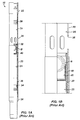
- FIG. 1A shows an example of a sliding sleeve 10 for a multi-zone fracturing system in partial cross-section in an opened state.
- This sliding sleeve 10 is similar to Weatherford's ZoneSelect MultiShift fracturing sliding sleeve and can be placed between isolation packers in a multi-zone completion.
- the sliding sleeve 10 includes a housing 20 defining a bore 25 and having upper and lower subs 22 and 24.
- An inner sleeve or insert 30 can be moved within the housing's bore 25 to open or close fluid flow through the housing's flow ports 26 based on the inner sleeve 30's position.
- the inner sleeve 30 When initially run downhole, the inner sleeve 30 positions in the housing 20 in a closed state.
- a breakable retainer 38 initially holds the inner sleeve 30 toward the upper sub 22, and a locking ring or dog 36 on the sleeve 30 fits into an annular slot within the housing 20.
- Outer seals on the inner sleeve 30 engage the housing 20's inner wall above and below the flow ports 26 to seal them off.
- the inner sleeve 30 defines a bore 35 having a seat 40 fixed therein.
- the sliding sleeve 10 can be opened when tubing pressure is applied against the seated ball 40 to move the inner sleeve 30 open.
- operators drop an appropriately sized ball B downhole and pump the ball B until it reaches the landing seat 40 disposed in the inner sleeve 30.
- the shear values required to open the sliding sleeves 10 can range generally from 1,000 to 4,000 psi (6.9 to 27.6 MPa).
- the well is typically flowed clean, and the ball B is floated to the surface. Then, the ball seat 40 (and the ball B if remaining) is milled out.
- the ball seat 40 can be constructed from cast iron to facilitate milling, and the ball B can be composed of aluminum or a non-metallic material, such as a composite.
- the inner sleeve 30 can be closed or opened with a standard "B" shifting tool on the tool profiles 32 and 34 in the inner sleeve 30 so the sliding sleeve 10 can then function like any conventional sliding sleeve shifting with a "B" tool.
- the ability to selectively open and close the sliding sleeve 10 enables operators to isolate the particular section of the assembly.
- the lowermost sliding sleeve 10 has a ball seat 40 for the smallest ball size, and successively higher sleeves 10 have larger seats 40 for larger balls B.
- a specific sized ball B dropped in the tubing string will pass though the seats 40 of upper sleeves 10 and only locate and seal at a desired seat 40 in the tubing string.
- FIGS 2A-2B illustrates another ball-actuated sliding sleeve 10 according to the prior art.
- a protective cover 27 can be disposed about the exterior of the sleeve's housing to cover the flow ports 26.
- the protective cover 27 is typically composed of a composite material and prevents debris, cement, and the like from entering the sliding sleeve's flow ports 26 before the sliding sleeve 10 is opened.
- the exterior of the sleeve's housing 20 may have a slot 29 to accommodate the cover 27 flush with the exterior of the housing 20.
- FIG. 3 illustrates another ball-actuated sliding sleeve 10 according to the prior art in partial cross-section.
- This ball-actuated sliding sleeve 10 counts balls of the same size before opening an inner sleeve 60.
- the sliding sleeve 10 includes a counter 50 and a separate seat 70.
- the sliding sleeve 10 also includes a protective cover 80 to protect the sliding sleeve's flow ports 26 during run in and other operations until open.
- the cover 80 may also initially hold grease or other filler material in the sleeve 10 during deployment.
- the protective cover 80 which is shown in more detail in Figures 4A-4C , is a thin sleeve and can be composed of an aluminum alloy.
- the protective cover 80 typically has a thickness t 1 of about 0.09-in. and has a diameter d 1 suited to fit around the outside of the housing 20, which may have a diameter of about 5.65-in.
- the cover 80 includes various holes or passages 84 defined from the inside 82 to the outside 86 that allow initial fluid flow from the open flow ports 26 to pass through the cover 80. Eventually, the flow, which may include proppant, erodes the cover 80 from around the housing 20 and flow ports 26, allowing the sliding sleeve 10 to be used for fracturing and other treatment operations.
- the subject matter of the present disclosure is directed to overcoming, or at least reducing the effects of, one or more of the problems set forth above.
- a sliding sleeve opens with a deployed plug.
- the sliding sleeve comprises a housing defining a first bore and defining a flow port communicating the first bore outside the housing.
- An inner sleeve defines a second bore and is movable axially inside the first bore from a closed position to an opened position relative to the flow port.
- a seat disposed in the sliding sleeve engages the deployed plug. Fluid pressure applied against the seated plug shears the insert free from the housing. For example, shear pins or other temporary attachment may hold the insert in the closed position, and the build-up of fluid pressure against the seated plug can break this attachment and allow the insert to move toward the opening position. This first pressure build-up and release may give a first indication that the sleeve has opened.
- a burst band is disposed about the exterior of the housing at the flow ports. Once the insert moves to the opened position, fluid pressure applied against the seated plug passes through the open flow ports and acts against the burst band. Eventually, the burst band, which can have a number of scores, indentations, or the like, breaks and permits flow of fluid from the flow ports to pass out of the housing. Bursting of the band and the associated build-up of pressure causing it provides a second pressure indication to operators at the surface that the sliding sleeve has opened.
- a downhole tool comprising:
- the insert may comprise a seat engaging a plug deployed therein, the insert moving from the closed position to the opened position in response to fluid pressure applied against the deployed plug engaged with the seat.
- a temporary attachment may hold the insert in the closed position and release the insert to move to the opened position in response to a second pressure level.
- the second pressure level may be less than the first pressure level.
- the second pressure level may be approximately 1,000 to 4,000 psi.
- the first pressure level may be approximately 1,500 to 4,300 psi.
- the first and second pressure levels may provide first and second respective indications at surface indicative of the insert moving to the opened position.
- the housing may comprise seals disposed about the housing and sealing the at least one port with an inside surface of the burst band.
- the burst band may be composed of a cast iron.
- the burst band may define at least one groove on an outside surface of the burst band.
- the at least one groove may be defined from end-to-end along an axis of the burst band.
- the housing may comprise first and second housing components coupling together end-to-end, the burst band inserting at least partially on one of the ends of one of the housing components.
- a method of opening a downhole tool comprising:
- Applying the first fluid pressure downhole to the downhole tool may comprise opening an insert in the downhole tool with the first applied fluid pressure.
- Obtaining the first pressure response indicative of opening of the downhole tool in response to the first applied fluid pressure may comprise shearing the insert to move in the downhole tool in response to a first pressure level of the first applied fluid pressure.
- the method may initially comprise deploying a plug downhole to a seat on the insert of the downhole tool.
- Applying the first fluid pressure downhole to the downhole tool may comprise applying the first fluid pressure against the deployed plug engaged against the seat on the insert in the downhole tool.
- Applying the second fluid pressure downhole to the downhole tool subsequent to the first pressure response may comprise diverting the second fluid pressure out of a flow port on the downhole tool and applying the diverted fluid pressure against a burst band disposed outside the downhole tool.
- Applying the diverted fluid pressure against the burst band disposed outside the downhole tool may comprise applying the diverted fluid pressure against the burst band in sealed engagement with the flow port of the downhole tool.
- Obtaining the second pressure response indicative of the opening of the downhole tool in response to the second applied fluid pressure may comprise bursting the burst sleeve away from the downhole tool in response to a second pressure level of the second applied fluid pressure.
- Figures 5A-5B illustrates a downhole tool 10 in partial cross-section having a burst band 100 according to the present disclosure.
- the downhole tool 10 can be a ball-actuated sliding sleeve 10, which deploys on a tubing string in a borehole and can be used for fracture operations.
- the sliding sleeve 10 includes a housing 20 defining a bore 25 and having upper and lower subs 22 and 24.
- An inner sleeve or insert 30 can be moved within the housing's bore 25 to open or close fluid flow through the housing's flow ports 26 based on the inner sleeve 30's position.
- the insert 30 When initially run downhole, the insert 30 positions in the housing 20 in a closed state covering the flow ports 26.
- a breakable retainer 38 initially holds the insert 30 toward the upper sub 22, and a locking ring or dog 36 on the insert 30 fits into an annular slot within the housing 20.
- Outer seals on the insert 30 engage the housing 20's inner wall above and below the flow ports 26 to seal them off. Shear pins and other known features can be used to hold the insert 30 in its closed state.
- the insert 30 defines a bore 35 having a seat 40 fixed therein.
- an appropriately sized plug e.g., ball, dart, etc.
- the sliding sleeve 10 can be opened when tubing pressure is applied against the seated ball 40 to move the insert 30 open.
- operators drop an appropriately sized ball B downhole and pump the ball B until it reaches the landing seat 40 disposed in the insert 30.
- a first surface indication can be produced when the ball B lands on the seat 40 and built-up pressure exceeds the shear value and shifts the insert 30 open.
- the value of this first surface indication can depend on the type of sliding sleeve 10 used, the operating pressure, shear values, and the like.
- the shear values required to open the insert 30 can range generally from 1,000 to 4,000 psi (6.9 to 27.6 MPa).
- the burst band 100 When the insert 30 moves open, applied fluid pressure diverted by the seated ball B acts against the burst band 100.
- the burst band 100 is disposed around the exterior of the sleeve's housing 20 and covers the flow ports 26.
- the burst band 100 can provide the conventional benefits of keeping out debris from the sleeve 10 and holding in any grease or the like.
- the burst band 100 produces a second surface indication as built-up pressure bursts the burst band 100.
- This second surface indication is expected to produce a signature pressure spike that can be preconfigured to a desired value for an implementation.
- the band 100 When it bursts, the band 100 preferably breaks into two or more pieces that fall away from the sleeve 10. It may be acceptable in some implementations to have the band 100 split at one location rather than breaking into pieces. In any event, if any piece remains adjacent the ports 26, the material can be eroded away during subsequent treatment operations.
- the burst band 100 is not connected to the internal workings of the sliding sleeve 10. Therefore, the burst band 100 is preferably disposed on the exterior of the housing 20, which may have an external slot 29 to accommodate the band 100.
- Fluid seals 28, such as O-rings or the like, can be disposed on the exterior of the housing 20 (and/or on the interior of the burst band 100 depending on the band's thickness). These seals 28 can contain the fluid pressure at least partially inside the sliding sleeve 10 once the insert 30 is opened. In other implementations, seals may not be used, or seals may be disposed on the band 100.
- the burst value or surface indication value indicative of the bursting of the burst band 100 can be much higher than traditional surface indication devices. Additionally, as shown in the graph of Figure 5C , two pressure spikes or surface indications may be produced during the opening of the sliding sleeve 10 downhole. In particular, the first indication results from the build-up and then release of fluid pressure applied against the seated ball B to shear the insert 30 open. Then, the second indication results from the build-up and then release of fluid pressure to burst the burst band 100 covering the flow ports 26. At surface using pressure measurements and known pressure devices, operators can then use the dual surface indications as further confirmation that the sliding sleeve 100 has successfully opened downhole.
- the burst band 100 is preferably composed of cast iron, although other materials could be used, including other metals or non-metallic materials.
- the burst band 100 can have a thickness t 2 of about 0.4-in, but the particular thickness t 2 can be configured for a particular implementation and desired burst pressure as disclosed herein.
- the diameter d 2 of the band 100 depends on the diameter of the sleeve's housing 20, and in one example, the band 100 may have an inside diameter d 2 of about 5.25-in for a 5.5-in. sliding sleeve.
- the height of the band 100 for such a sliding sleeve may be about 3.2-in. Inside edges of the band 100 can be beveled at 15 to 30 degrees for about 0.1-in. Again, the particulars of the diameter, height, and the like of the burst band 100 can be configured for a particular implementation and desired burst pressure as disclosed herein.
- a plurality of scores 104, indications, slots, grooves, or the like can be defined around the burst band 100 to facilitate rupture of the band 100 caused by internal pressure applied against the inner surface 102 of the band 100.
- the scores 104 can be machined or formed in appropriate ways and are preferably defined on the exterior surface 106 of the band 100. Additionally, the scores 104 preferably run along the longitudinal axis of the band 100 from the top to the bottom to promote splitting of the band 100.
- the depth of the scores 104 can depend on the implementation and other factors (e.g., thickness of band 100, material used, burst pressure desired, etc.). In general, the scores 104 may have a depth of about 0.005 to 0.015-in., and they may define V-shaped profiles with sides angled at 45-degrees.
- any suitable number of scores 104 may be provided on the band 100, and four are shown in the present example.
- the number of scores 104 used about the circumference of the band 100 can be configured to facilitate bursting at a desired pressure and/or producing a desired number of burst pieces of the band 100.
- at least two scores 104 are provided so that the band 100 breaks into two or more pieces.
- four scores 104 are defined at every 90-degrees around the circumference of the band 100.
- the pressure level required to burst the band 100 is configured by the thickness t 2 of the band 100, the material of the band 100, the diameter d 2 of the band 100, the number of flow ports 26 exposed to the band 100, the number of scores 104 defined, the depth of the scores 104, and other factors.
- FIG. 7 illustrates another downhole tool 10 in partial cross-section having a burst band 100 according to the present disclosure.
- This downhole tool 10 is a ball-actuated sliding sleeve that counts passage of same-sized balls before opening and is similar to the sliding sleeve disclosed in US 2013/0186644 and US 2013/0025868 , which are incorporated herein by reference in their entireties.
- the sliding sleeve 10 includes a counter 50, an insert 60, and a separate seat 70.
- the insert 60 has flow passages 66 and seals inside the housing 26. When the insert 60 is shifted, the insert's passages 66 align with the flow ports 26 to allow fluid flow out of the sliding sleeve 10.
- the sliding sleeve 10 includes the burst band 100 disposed about the housing 20 around the location of the flow ports 26. Indication of the opening of this insert 60 may come primarily by the bursting of the band 100, since a shear pin or other temporary retainer may not hold the insert 60 closed. Yet, the pressure response from the counter 50 and/or seat 70 can be used as another indication.
- the housing 20 includes seals 28, such as O-rings disposed around the housing 20 both above and below the flow ports 26. Other forms of sealing can be used.
- the housing 20 of the sliding sleeve 10 may include separate housing components.
- Figure 8A illustrates a cross-sectional view of an upper housing component 21 a for the ball-actuated sliding sleeve 10 of Figure 6 .
- Figures 8B-8C illustrate cross-sectional and end-sectional views of another housing component 21 b of the ball-actuated sliding sleeve 10 of Figure 6 .
- These two housing components 21 a-b couple together with the burst band (not shown) disposed around their junction at the location of the flow ports 26.
- Both components 21 a-b define annular slots 28 for holding O-ring seals on the exterior to engage against the inside surface of the burst band (not shown).
- Figure 9A illustrates burst calculations for four tests on different configurations of burst bands 100 according to the present disclosure.
- the burst bands 100 are composed of a cast iron.
- the charts for each of the calculations show the outside and inside diameters (minimum, nominal, maximum) of the burst band 100, ultimate tensile strength, the band's wall thickness, the ratio of the outside diameter to the wall thickness, a correction factor, and thin and thick wall based calculations.
- the band 100 has a first thickness of about 0.188-in., and it is calculated to burst at a burst pressure ranging from about 3732 to 4258-psi, depending on the various factors.
- a burst band 100 having this first thickness and having a 0.009-in groove depth for the scores was subject to burst pressure from flow ports on a sliding sleeve. The band 100 was observed to burst at 3920-psi into two overall pieces.
- the band 100 has a second thickness of about 0.172-in., and it is calculated to burst at a burst pressure ranging from about 2479 to 2821-psi, depending on the various factors.
- a burst band having this second thickness and having a 0.025-in groove depth for the scores was observed to burst at 2608-psi into three overall pieces.
- the band 100 has a third thickness of about 0.138-in., and it is calculated to burst at a burst pressure ranging from about 1523 to 1723-psi, depending on the various factors.
- a burst band having this third thickness and having a 0.059-in groove depth for the scores was observed to burst at 1602-psi into two overall pieces.
- the band 100 has a fourth thickness of about 0.152-in., and it is calculated to burst at a burst pressure ranging from about 1879 to 2132-psi, depending on the various factors.
- a burst band having this fourth thickness and having a 0.045-in groove depth for the scores was observed to burst at 1977-psi into two overall pieces.
- Figure 9B graphs the correlation between the calculated burst pressures of the burst bands 100 to the outside diameters of the burst bands 100 for a range between 5.52-in to 5.64-in. This correlation graphs as a polynomial equation and can be used to configure the particular factors of a burst band 100 for a particular implementation and desired burst pressure.
Landscapes
- Geology (AREA)
- Life Sciences & Earth Sciences (AREA)
- Engineering & Computer Science (AREA)
- Mining & Mineral Resources (AREA)
- Environmental & Geological Engineering (AREA)
- Fluid Mechanics (AREA)
- Physics & Mathematics (AREA)
- General Life Sciences & Earth Sciences (AREA)
- Geochemistry & Mineralogy (AREA)
- Pressure Vessels And Lids Thereof (AREA)
- Earth Drilling (AREA)
- Safety Valves (AREA)
- Pipe Accessories (AREA)
Abstract
Description
- This application claims the benefit of
U.S. Provisional Appl. 61/911,614, filed 04-DEC-2013 - In a staged fracturing operation, multiple zones of a formation need to be isolated sequentially for treatment. To achieve this, operators install a fracturing assembly down the wellbore, which typically has a top liner packer, open hole packers isolating the wellbore into zones, various sliding sleeves, and a wellbore isolation valve. When the zones do not need to be closed after opening, operators may use single shot sliding sleeves for the fracturing treatment. These types of sleeves are usually ball-actuated and lock open once actuated. Another type of sleeve is also ball-actuated, but can be shifted closed after opening.
- Initially, operators run the fracturing assembly in the wellbore with all of the sliding sleeves closed and with the wellbore isolation valve open. Operators then deploy a setting ball to close the wellbore isolation valve. This seals off the tubing string of the assembly so the packers can be hydraulically set. At this point, operators rig up fracturing surface equipment and pump fluid down the wellbore to open a pressure actuated sleeve so a first zone can be treated.
- As the operation continues, operates drop successively larger balls down the tubing string and pump fluid to treat the separate zones in stages. When a dropped ball meets its matching seat in a sliding sleeve, the pumped fluid forced against the seated ball shifts the sleeve open. In turn, the seated ball diverts the pumped fluid into the adjacent zone and prevents the fluid from passing to lower zones. By dropping successively increasing sized balls to actuate corresponding sleeves, operators can accurately treat each zone up the wellbore.
-
Figure 1A shows an example of asliding sleeve 10 for a multi-zone fracturing system in partial cross-section in an opened state. Thissliding sleeve 10 is similar to Weatherford's ZoneSelect MultiShift fracturing sliding sleeve and can be placed between isolation packers in a multi-zone completion. The slidingsleeve 10 includes ahousing 20 defining abore 25 and having upper andlower subs insert 30 can be moved within the housing's bore 25 to open or close fluid flow through the housing'sflow ports 26 based on theinner sleeve 30's position. - When initially run downhole, the
inner sleeve 30 positions in thehousing 20 in a closed state. Abreakable retainer 38 initially holds theinner sleeve 30 toward theupper sub 22, and a locking ring ordog 36 on thesleeve 30 fits into an annular slot within thehousing 20. Outer seals on theinner sleeve 30 engage thehousing 20's inner wall above and below theflow ports 26 to seal them off. - The
inner sleeve 30 defines abore 35 having aseat 40 fixed therein. When an appropriately sized ball lands on theseat 40, thesliding sleeve 10 can be opened when tubing pressure is applied against theseated ball 40 to move theinner sleeve 30 open. To open the slidingsleeve 10 in a fracturing operation once the appropriate amount of proppant has been pumped into a lower formation's zone, for example, operators drop an appropriately sized ball B downhole and pump the ball B until it reaches thelanding seat 40 disposed in theinner sleeve 30. - Once the ball B is seated, built up pressure forces against the
inner sleeve 30 in thehousing 20, shearing thebreakable retainer 38 and freeing the lock ring ordog 36 from the housing's annular slot so theinner sleeve 30 can slide downward. As it slides, theinner sleeve 30 uncovers theflow ports 26 so flow can be diverted to the surrounding formation. The shear values required to open thesliding sleeves 10 can range generally from 1,000 to 4,000 psi (6.9 to 27.6 MPa). - Once the
sleeve 10 is open, operators can then pump proppant at high pressure down the tubing string to theopen sleeve 10. The proppant and high pressure fluid flows out of theopen flow ports 26 as the seated ball B prevents fluid and proppant from communicating further down the tubing string. The pressures used in the fracturing operation can reach as high as 15,000-psi. - After the fracturing job, the well is typically flowed clean, and the ball B is floated to the surface. Then, the ball seat 40 (and the ball B if remaining) is milled out. The
ball seat 40 can be constructed from cast iron to facilitate milling, and the ball B can be composed of aluminum or a non-metallic material, such as a composite. Once milling is complete, theinner sleeve 30 can be closed or opened with a standard "B" shifting tool on thetool profiles inner sleeve 30 so thesliding sleeve 10 can then function like any conventional sliding sleeve shifting with a "B" tool. The ability to selectively open and close the slidingsleeve 10 enables operators to isolate the particular section of the assembly. - Because the zones of a formation are treated in stages with the
sliding sleeves 10, the lowermostsliding sleeve 10 has aball seat 40 for the smallest ball size, and successivelyhigher sleeves 10 havelarger seats 40 for larger balls B. In this way, a specific sized ball B dropped in the tubing string will pass though theseats 40 ofupper sleeves 10 and only locate and seal at a desiredseat 40 in the tubing string. Despite the effectiveness of such an assembly, practical limitations restrict the number of balls B that can be effectively run in a single tubing string. -
Figures 2A-2B illustrates another ball-actuated slidingsleeve 10 according to the prior art. To protect thesleeve 10 during run-in, cementing in the borehole, and the like, aprotective cover 27 can be disposed about the exterior of the sleeve's housing to cover theflow ports 26. Theprotective cover 27 is typically composed of a composite material and prevents debris, cement, and the like from entering the sliding sleeve'sflow ports 26 before the slidingsleeve 10 is opened. The exterior of the sleeve'shousing 20 may have aslot 29 to accommodate thecover 27 flush with the exterior of thehousing 20. When thesliding sleeve 10 is opened, fluid pressure from theflow ports 26 readily breaks the compositeprotective cover 27. -
Figure 3 illustrates another ball-actuatedsliding sleeve 10 according to the prior art in partial cross-section. This ball-actuated slidingsleeve 10 counts balls of the same size before opening aninner sleeve 60. To do this, thesliding sleeve 10 includes acounter 50 and aseparate seat 70. In a similar fashion to the sliding sleeve discussed above, thesliding sleeve 10 also includes aprotective cover 80 to protect the sliding sleeve'sflow ports 26 during run in and other operations until open. Thecover 80 may also initially hold grease or other filler material in thesleeve 10 during deployment. - The
protective cover 80, which is shown in more detail inFigures 4A-4C , is a thin sleeve and can be composed of an aluminum alloy. Theprotective cover 80 typically has a thickness t1 of about 0.09-in. and has a diameter d1 suited to fit around the outside of thehousing 20, which may have a diameter of about 5.65-in. Thecover 80 includes various holes orpassages 84 defined from theinside 82 to theoutside 86 that allow initial fluid flow from theopen flow ports 26 to pass through thecover 80. Eventually, the flow, which may include proppant, erodes thecover 80 from around thehousing 20 andflow ports 26, allowing thesliding sleeve 10 to be used for fracturing and other treatment operations. - During operations deploying balls to actuate the sliding sleeves downhole to treat various zones, operators want to detect an identifiable pressure spike at surface that helps indicate that a sliding sleeve has opened downhole. Currently, the sliding sleeves attempt to create a suitable surface indication using shear screws, shear rings, and the like in the sliding sleeves. When the deployed ball lands on the seat in the sliding sleeve, fluid pressure applied against the seated ball breaks the shear screws to shift the insert open in the sliding sleeve. The pressure spike and fall off measured at the surface resulting from the build up and release of pressure that break the shear screws can be used by operators to determine that the sliding sleeve has opened. In some cases, the pressure spike is insufficient to indicate opening of the sliding sleeve.
- The subject matter of the present disclosure is directed to overcoming, or at least reducing the effects of, one or more of the problems set forth above.
- As disclosed herein, a sliding sleeve opens with a deployed plug. The sliding sleeve comprises a housing defining a first bore and defining a flow port communicating the first bore outside the housing. An inner sleeve defines a second bore and is movable axially inside the first bore from a closed position to an opened position relative to the flow port. A seat disposed in the sliding sleeve engages the deployed plug. Fluid pressure applied against the seated plug shears the insert free from the housing. For example, shear pins or other temporary attachment may hold the insert in the closed position, and the build-up of fluid pressure against the seated plug can break this attachment and allow the insert to move toward the opening position. This first pressure build-up and release may give a first indication that the sleeve has opened.
- A burst band is disposed about the exterior of the housing at the flow ports. Once the insert moves to the opened position, fluid pressure applied against the seated plug passes through the open flow ports and acts against the burst band. Eventually, the burst band, which can have a number of scores, indentations, or the like, breaks and permits flow of fluid from the flow ports to pass out of the housing. Bursting of the band and the associated build-up of pressure causing it provides a second pressure indication to operators at the surface that the sliding sleeve has opened.
- According to the present disclosure there is provided a downhole tool, comprising:
- a housing defining an internal bore and defining at least one port communicating the internal bore outside the housing;
- an insert disposed in the internal bore and movable at least from a closed position to an opened position relative to the at least one port; and
- a burst band disposed outside the housing at the at least one port, the burst band breaking away from the housing in response to a first pressure level communicated through the at least one port when the insert is in the opened position.
- The insert may comprise a seat engaging a plug deployed therein, the insert moving from the closed position to the opened position in response to fluid pressure applied against the deployed plug engaged with the seat.
- A temporary attachment may hold the insert in the closed position and release the insert to move to the opened position in response to a second pressure level.
- The second pressure level may be less than the first pressure level.
- The second pressure level may be approximately 1,000 to 4,000 psi.
- The first pressure level may be approximately 1,500 to 4,300 psi.
- The first and second pressure levels may provide first and second respective indications at surface indicative of the insert moving to the opened position.
- The housing may comprise seals disposed about the housing and sealing the at least one port with an inside surface of the burst band.
- The burst band may be composed of a cast iron.
- The burst band may define at least one groove on an outside surface of the burst band.
- The at least one groove may be defined from end-to-end along an axis of the burst band.
- The housing may comprise first and second housing components coupling together end-to-end, the burst band inserting at least partially on one of the ends of one of the housing components.
- According to the present disclosure there is provided a method of opening a downhole tool, the method comprising:
- applying first fluid pressure downhole to the downhole tool;
- obtaining a first pressure response indicative of opening of the downhole tool in response to the first applied fluid pressure;
- applying second fluid pressure downhole to the downhole tool subsequent to the first pressure response; and
- obtaining a second pressure response indicative of the opening of the downhole tool in response to the second applied fluid pressure.
- Applying the first fluid pressure downhole to the downhole tool may comprise opening an insert in the downhole tool with the first applied fluid pressure.
- Obtaining the first pressure response indicative of opening of the downhole tool in response to the first applied fluid pressure may comprise shearing the insert to move in the downhole tool in response to a first pressure level of the first applied fluid pressure.
- The method may initially comprise deploying a plug downhole to a seat on the insert of the downhole tool.
- Applying the first fluid pressure downhole to the downhole tool may comprise applying the first fluid pressure against the deployed plug engaged against the seat on the insert in the downhole tool.
- Applying the second fluid pressure downhole to the downhole tool subsequent to the first pressure response may comprise diverting the second fluid pressure out of a flow port on the downhole tool and applying the diverted fluid pressure against a burst band disposed outside the downhole tool.
- Applying the diverted fluid pressure against the burst band disposed outside the downhole tool may comprise applying the diverted fluid pressure against the burst band in sealed engagement with the flow port of the downhole tool.
- Obtaining the second pressure response indicative of the opening of the downhole tool in response to the second applied fluid pressure may comprise bursting the burst sleeve away from the downhole tool in response to a second pressure level of the second applied fluid pressure.
-
-
Fig. 1A illustrates a ball-actuated sliding sleeve according to the prior art in partial cross-section. -
Fig. 1B illustrates a detailed view of the ball-actuated sliding sleeve ofFig. 1A . -
Figs. 2A-2B illustrates another ball-actuated sliding sleeve according to the prior art. -
Fig. 3 illustrates yet another ball-actuated sliding sleeve according to the prior art having a protective cover. -
Figs. 4A-4C illustrate perspective, end-sectional, and cross-sectional views of a protective cover according to the prior art. -
Figs. 5A-5B illustrates a ball-actuated sliding sleeve in partial cross-section having a burst band according to the present disclosure. -
Fig. 5C graphs an example of surface indications resulting from the opening of the ball-actuated sliding sleeve having the burst band. -
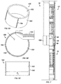
Figs. 6A-6C illustrate perspective, end-sectional, and cross-sectional views of an burst band according to the present disclosure. -
Fig. 7 illustrates another ball-actuated sliding sleeve in partial cross-section having a burst band according to the present disclosure. -
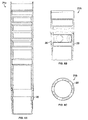
Fig. 8A illustrate a cross-sectional view of an upper housing component for the ball-actuated sliding sleeve ofFig. 6 . -
Figs. 8B-8C illustrate cross-sectional and end-sectional views of another housing component of the ball-actuated sliding sleeve ofFig. 6 . -
Fig. 9A illustrates burst calculations for a four tests on different configurations of burst bands according to the present disclosure. -
Fig. 9B graphs the correlation between the burst pressure of the burst bands to the diameter of the burst band. -
Figures 5A-5B illustrates adownhole tool 10 in partial cross-section having aburst band 100 according to the present disclosure. As shown, thedownhole tool 10 can be a ball-actuated slidingsleeve 10, which deploys on a tubing string in a borehole and can be used for fracture operations. The slidingsleeve 10 includes ahousing 20 defining abore 25 and having upper andlower subs flow ports 26 based on theinner sleeve 30's position. - When initially run downhole, the
insert 30 positions in thehousing 20 in a closed state covering theflow ports 26. Abreakable retainer 38 initially holds theinsert 30 toward theupper sub 22, and a locking ring ordog 36 on theinsert 30 fits into an annular slot within thehousing 20. Outer seals on theinsert 30 engage thehousing 20's inner wall above and below theflow ports 26 to seal them off. Shear pins and other known features can be used to hold theinsert 30 in its closed state. - The
insert 30 defines abore 35 having aseat 40 fixed therein. When an appropriately sized plug (e.g., ball, dart, etc.) lands on theseat 40, the slidingsleeve 10 can be opened when tubing pressure is applied against the seatedball 40 to move theinsert 30 open. To open the slidingsleeve 10 in a fracturing operation once the appropriate amount of proppant has been pumped into a lower formation's zone, for example, operators drop an appropriately sized ball B downhole and pump the ball B until it reaches the landingseat 40 disposed in theinsert 30. - Once the ball B is seated, built-up pressure forces push against the
insert 30 in thehousing 20, eventually shearing thebreakable retainer 38 and freeing the lock ring ordog 36 from the housing's annular slot. Theinsert 30 can then slide downward. As it slides, theinsert 30 uncovers theflow ports 26. - During opening of the sliding
sleeve 10, a first surface indication can be produced when the ball B lands on theseat 40 and built-up pressure exceeds the shear value and shifts theinsert 30 open. The value of this first surface indication can depend on the type of slidingsleeve 10 used, the operating pressure, shear values, and the like. The shear values required to open theinsert 30 can range generally from 1,000 to 4,000 psi (6.9 to 27.6 MPa). - When the
insert 30 moves open, applied fluid pressure diverted by the seated ball B acts against theburst band 100. As initially discussed, theburst band 100 is disposed around the exterior of the sleeve'shousing 20 and covers theflow ports 26. Thus, theburst band 100 can provide the conventional benefits of keeping out debris from thesleeve 10 and holding in any grease or the like. - In addition to these conventional benefits, however, the
burst band 100 produces a second surface indication as built-up pressure bursts theburst band 100. This second surface indication is expected to produce a signature pressure spike that can be preconfigured to a desired value for an implementation. Once theburst band 100 bursts, the slidingsleeve 10 is open to the borehole, and operators at the surface detecting the signature pressure spike can determine that thesleeve 10 has opened downhole successfully. - When it bursts, the
band 100 preferably breaks into two or more pieces that fall away from thesleeve 10. It may be acceptable in some implementations to have theband 100 split at one location rather than breaking into pieces. In any event, if any piece remains adjacent theports 26, the material can be eroded away during subsequent treatment operations. - Once the
sleeve 10 is open, operators can then pump proppant at high pressure down the tubing string to theopen sleeve 10. The proppant and high pressure fluid flows out of theopen flow ports 26 as the seated ball B prevents fluid and proppant from communicating further down the tubing string. The pressures used in the fracturing operation can reach as high as 15,000-psi. - Preferably as shown, the
burst band 100 is not connected to the internal workings of the slidingsleeve 10. Therefore, theburst band 100 is preferably disposed on the exterior of thehousing 20, which may have anexternal slot 29 to accommodate theband 100. Fluid seals 28, such as O-rings or the like, can be disposed on the exterior of the housing 20 (and/or on the interior of theburst band 100 depending on the band's thickness). Theseseals 28 can contain the fluid pressure at least partially inside the slidingsleeve 10 once theinsert 30 is opened. In other implementations, seals may not be used, or seals may be disposed on theband 100. - The burst value or surface indication value indicative of the bursting of the
burst band 100 can be much higher than traditional surface indication devices. Additionally, as shown in the graph ofFigure 5C , two pressure spikes or surface indications may be produced during the opening of the slidingsleeve 10 downhole. In particular, the first indication results from the build-up and then release of fluid pressure applied against the seated ball B to shear theinsert 30 open. Then, the second indication results from the build-up and then release of fluid pressure to burst theburst band 100 covering theflow ports 26. At surface using pressure measurements and known pressure devices, operators can then use the dual surface indications as further confirmation that the slidingsleeve 100 has successfully opened downhole. - Turning now to
Figures 6A-6C , details of one embodiment of aburst band 100 are shown in various views. Theburst band 100 is preferably composed of cast iron, although other materials could be used, including other metals or non-metallic materials. Theburst band 100 can have a thickness t2 of about 0.4-in, but the particular thickness t2 can be configured for a particular implementation and desired burst pressure as disclosed herein. The diameter d2 of theband 100 depends on the diameter of the sleeve'shousing 20, and in one example, theband 100 may have an inside diameter d2 of about 5.25-in for a 5.5-in. sliding sleeve. The height of theband 100 for such a sliding sleeve may be about 3.2-in. Inside edges of theband 100 can be beveled at 15 to 30 degrees for about 0.1-in. Again, the particulars of the diameter, height, and the like of theburst band 100 can be configured for a particular implementation and desired burst pressure as disclosed herein. - A plurality of
scores 104, indications, slots, grooves, or the like can be defined around theburst band 100 to facilitate rupture of theband 100 caused by internal pressure applied against theinner surface 102 of theband 100. Thescores 104 can be machined or formed in appropriate ways and are preferably defined on theexterior surface 106 of theband 100. Additionally, thescores 104 preferably run along the longitudinal axis of theband 100 from the top to the bottom to promote splitting of theband 100. - The depth of the
scores 104 can depend on the implementation and other factors (e.g., thickness ofband 100, material used, burst pressure desired, etc.). In general, thescores 104 may have a depth of about 0.005 to 0.015-in., and they may define V-shaped profiles with sides angled at 45-degrees. - Any suitable number of
scores 104 may be provided on theband 100, and four are shown in the present example. The number ofscores 104 used about the circumference of theband 100 can be configured to facilitate bursting at a desired pressure and/or producing a desired number of burst pieces of theband 100. Preferably, at least twoscores 104 are provided so that theband 100 breaks into two or more pieces. In one particular arrangement, fourscores 104 are defined at every 90-degrees around the circumference of theband 100. - Overall, the pressure level required to burst the
band 100 is configured by the thickness t2 of theband 100, the material of theband 100, the diameter d2 of theband 100, the number offlow ports 26 exposed to theband 100, the number ofscores 104 defined, the depth of thescores 104, and other factors. -
Figure 7 illustrates anotherdownhole tool 10 in partial cross-section having aburst band 100 according to the present disclosure. Thisdownhole tool 10 is a ball-actuated sliding sleeve that counts passage of same-sized balls before opening and is similar to the sliding sleeve disclosed inUS 2013/0186644 andUS 2013/0025868 , which are incorporated herein by reference in their entireties. To do this counting, the slidingsleeve 10 includes acounter 50, aninsert 60, and aseparate seat 70. Theinsert 60 hasflow passages 66 and seals inside thehousing 26. When theinsert 60 is shifted, the insert'spassages 66 align with theflow ports 26 to allow fluid flow out of the slidingsleeve 10. - To help operators determine opening of the sliding sleeve's
insert 60 inside thehousing 20, the slidingsleeve 10 includes theburst band 100 disposed about thehousing 20 around the location of theflow ports 26. Indication of the opening of thisinsert 60 may come primarily by the bursting of theband 100, since a shear pin or other temporary retainer may not hold theinsert 60 closed. Yet, the pressure response from thecounter 50 and/orseat 70 can be used as another indication. To help seal theburst band 100 in place, thehousing 20 includesseals 28, such as O-rings disposed around thehousing 20 both above and below theflow ports 26. Other forms of sealing can be used. - To facilitate assembly of the
burst band 100 on the slidingsleeve 10, thehousing 20 of the slidingsleeve 10 may include separate housing components. For example,Figure 8A illustrates a cross-sectional view of anupper housing component 21 a for the ball-actuated slidingsleeve 10 ofFigure 6 .Figures 8B-8C illustrate cross-sectional and end-sectional views of anotherhousing component 21 b of the ball-actuated slidingsleeve 10 ofFigure 6 . These two housing components 21 a-b couple together with the burst band (not shown) disposed around their junction at the location of theflow ports 26. Both components 21 a-b defineannular slots 28 for holding O-ring seals on the exterior to engage against the inside surface of the burst band (not shown). - As noted above, the pressure at which the
burst band 100 bursts depends on a number of factors and can be configured for a particular implementation. For example,Figure 9A illustrates burst calculations for four tests on different configurations of burstbands 100 according to the present disclosure. In each of the burst test calculations, the burstbands 100 are composed of a cast iron. - The charts for each of the calculations show the outside and inside diameters (minimum, nominal, maximum) of the
burst band 100, ultimate tensile strength, the band's wall thickness, the ratio of the outside diameter to the wall thickness, a correction factor, and thin and thick wall based calculations. In the first test calculation (Test 1), theband 100 has a first thickness of about 0.188-in., and it is calculated to burst at a burst pressure ranging from about 3732 to 4258-psi, depending on the various factors. In a first test run, aburst band 100 having this first thickness and having a 0.009-in groove depth for the scores was subject to burst pressure from flow ports on a sliding sleeve. Theband 100 was observed to burst at 3920-psi into two overall pieces. - In the second test calculation (Test 2), the
band 100 has a second thickness of about 0.172-in., and it is calculated to burst at a burst pressure ranging from about 2479 to 2821-psi, depending on the various factors. In a second test run, a burst band having this second thickness and having a 0.025-in groove depth for the scores was observed to burst at 2608-psi into three overall pieces. - In the third test calculation (Test 3), the
band 100 has a third thickness of about 0.138-in., and it is calculated to burst at a burst pressure ranging from about 1523 to 1723-psi, depending on the various factors. In a third test run, a burst band having this third thickness and having a 0.059-in groove depth for the scores was observed to burst at 1602-psi into two overall pieces. - In the fourth test calculation (Test 4), the
band 100 has a fourth thickness of about 0.152-in., and it is calculated to burst at a burst pressure ranging from about 1879 to 2132-psi, depending on the various factors. In a fourth test run, a burst band having this fourth thickness and having a 0.045-in groove depth for the scores was observed to burst at 1977-psi into two overall pieces. - Finally,
Figure 9B graphs the correlation between the calculated burst pressures of the burstbands 100 to the outside diameters of the burstbands 100 for a range between 5.52-in to 5.64-in. This correlation graphs as a polynomial equation and can be used to configure the particular factors of aburst band 100 for a particular implementation and desired burst pressure. - The foregoing description of preferred and other embodiments is not intended to limit or restrict the scope or applicability of the inventive concepts conceived of by the Applicants. For example, although the present disclosure focuses on verifying the opening of a sliding sleeve, such as a fracture sleeve, opened by a deployed plug or ball, the teachings of the present disclosure can apply to any other type of downhole tool used on a tubing string, such as a pressure-actuated sleeve, a ball-actuated sleeve, a toe sleeve, a stage tool, and the like.
- It will be appreciated with the benefit of the present disclosure that features described above in accordance with any embodiment or aspect of the disclosed subject matter can be utilized, either alone or in combination, with any other described feature, in any other embodiment or aspect of the disclosed subject matter.
- In exchange for disclosing the inventive concepts contained herein, the Applicants desire all patent rights afforded by the appended claims. Therefore, it is intended that the appended claims include all modifications and alterations to the full extent that they come within the scope of the following claims or the equivalents thereof.
Claims (15)
- A downhole tool, comprising:a housing defining an internal bore and defining at least one port communicating the internal bore outside the housing;an insert disposed in the internal bore and movable at least from a closed position to an opened position relative to the at least one port; anda burst band disposed outside the housing at the at least one port, the burst band breaking away from the housing in response to a first pressure level communicated through the at least one port when the insert is in the opened position.
- The tool of claim 1, wherein the insert comprises a seat engaging a plug deployed therein, the insert moving from the closed position to the opened position in response to fluid pressure applied against the deployed plug engaged with the seat.
- The tool of claim 1 or 2, wherein a temporary attachment holds the insert in the closed position and releases the insert to move to the opened position in response to a second pressure level.
- The tool of claim 3, wherein the second pressure level is less than the first pressure level, or
wherein the second pressure level is approximately 1,000 to 4,000 psi, or
wherein the first pressure level is approximately 1,500 to 4,300 psi. - The tool of claim 3 or 4, wherein the first and second pressure levels provide first and second respective indications at surface indicative of the insert moving to the opened position.
- The tool of any preceding claim, wherein the housing comprises seals disposed about the housing and sealing the at least one port with an inside surface of the burst band, or wherein the housing comprises first and second housing components coupling together end-to-end, the burst band inserting at least partially on one of the ends of one of the housing components.
- The tool of any preceding claim, wherein the burst band is composed of a cast iron.
- The tool of any preceding claim, wherein the burst band defines at least one groove on an outside surface of the burst band, and optionally
wherein the at least one groove is defined from end-to-end along an axis of the burst band. - A method of opening a downhole tool, the method comprising:applying first fluid pressure downhole to the downhole tool;obtaining a first pressure response indicative of opening of the downhole tool in response to the first applied fluid pressure;applying second fluid pressure downhole to the downhole tool subsequent to the first pressure response; andobtaining a second pressure response indicative of the opening of the downhole tool in response to the second applied fluid pressure.
- The method of claim 9, wherein applying the first fluid pressure downhole to the downhole tool comprises opening an insert in the downhole tool with the first applied fluid pressure, and optionally
wherein obtaining the first pressure response indicative of opening of the downhole tool in response to the first applied fluid pressure comprises shearing the insert to move in the downhole tool in response to a first pressure level of the first applied fluid pressure. - The method of claim 9 or 10, initially comprising deploying a plug downhole to a seat on the insert of the downhole tool.
- The method of claim 11, wherein applying the first fluid pressure downhole to the downhole tool comprises applying the first fluid pressure against the deployed plug engaged against the seat on the insert in the downhole tool.
- The method of claim 12, wherein applying the second fluid pressure downhole to the downhole tool subsequent to the first pressure response comprises diverting the second fluid pressure out of a flow port on the downhole tool and applying the diverted fluid pressure against a burst band disposed outside the downhole tool.
- The method of claim 13, wherein applying the diverted fluid pressure against the burst band disposed outside the downhole tool comprises applying the diverted fluid pressure against the burst band in sealed engagement with the flow port of the downhole tool.
- The method of claim 13 or 14, wherein obtaining the second pressure response indicative of the opening of the downhole tool in response to the second applied fluid pressure comprises bursting the burst sleeve away from the downhole tool in response to a second pressure level of the second applied fluid pressure.
Applications Claiming Priority (1)
| Application Number | Priority Date | Filing Date | Title |
|---|---|---|---|
| US201361911614P | 2013-12-04 | 2013-12-04 |
Publications (3)
| Publication Number | Publication Date |
|---|---|
| EP2881536A2 true EP2881536A2 (en) | 2015-06-10 |
| EP2881536A3 EP2881536A3 (en) | 2016-04-20 |
| EP2881536B1 EP2881536B1 (en) | 2018-01-31 |
Family
ID=52015924
Family Applications (1)
| Application Number | Title | Priority Date | Filing Date |
|---|---|---|---|
| EP14196403.1A Not-in-force EP2881536B1 (en) | 2013-12-04 | 2014-12-04 | Burst sleeve and positive indication for fracture sleeve opening |
Country Status (6)
| Country | Link |
|---|---|
| US (1) | US9885224B2 (en) |
| EP (1) | EP2881536B1 (en) |
| AU (1) | AU2014271275B2 (en) |
| CA (1) | CA2873153C (en) |
| NO (1) | NO3044084T3 (en) |
| RU (1) | RU2611083C2 (en) |
Cited By (1)
| Publication number | Priority date | Publication date | Assignee | Title |
|---|---|---|---|---|
| CN105003227A (en) * | 2015-08-03 | 2015-10-28 | 中国石油集团川庆钻探工程有限公司 | Separable hydraulic sliding sleeve for oil and gas wells |
Families Citing this family (13)
| Publication number | Priority date | Publication date | Assignee | Title |
|---|---|---|---|---|
| US9909384B2 (en) * | 2011-03-02 | 2018-03-06 | Team Oil Tools, Lp | Multi-actuating plugging device |
| WO2017132744A1 (en) | 2016-02-03 | 2017-08-10 | Tartan Completion Systems Inc. | Burst plug assembly with choke insert, fracturing tool and method of fracturing with same |
| US10487622B2 (en) | 2017-04-27 | 2019-11-26 | Baker Hughes, A Ge Company, Llc | Lock ring hold open device for frac sleeve |
| RU181716U1 (en) * | 2017-12-27 | 2018-07-26 | Акционерное общество "ОКБ Зенит" АО "ОКБ Зенит" | FOLT HYDRAULIC CLUTCH WITH SOLUBLE SEAT |
| US11156050B1 (en) | 2018-05-04 | 2021-10-26 | Paramount Design LLC | Methods and systems for degrading downhole tools containing magnesium |
| US11035197B2 (en) * | 2019-09-24 | 2021-06-15 | Exacta-Frac Energy Services, Inc. | Anchoring extrusion limiter for non-retrievable packers and composite frac plug incorporating same |
| RU2739882C1 (en) * | 2019-11-26 | 2020-12-29 | Симойл Пте. Лтд. | Multi-stage hydraulic fracturing coupling |
| RU2740460C1 (en) * | 2020-06-26 | 2021-01-14 | Общество с ограниченной ответственностью "Российская инновационная топливно-энергетическая компания" (ООО "РИТЭК") | Device for multistage hydraulic fracturing of formation and method for multi-stage hydraulic fracturing of formation using device thereof |
| RU2741884C1 (en) * | 2020-11-03 | 2021-01-29 | Общество с ограниченной ответственностью «УралНИПИнефть» | Soluble valve for the multi-stage hydraulic formation fracturing |
| CN112709549B (en) * | 2021-01-13 | 2024-09-17 | 天津德瑞克石油工具有限公司 | Binary ball-throwing counting cluster sliding sleeve |
| RU2765186C1 (en) * | 2021-03-23 | 2022-01-26 | Тарасов Алексей Сергеевич | Formation hydraulic fracturing method (options) and coupling for its implementation |
| CN113803027B (en) * | 2021-09-09 | 2024-01-30 | 中石化石油工程技术服务有限公司 | Oil well fracturing sliding sleeve used in combination with soluble fracturing ball |
| US12123281B2 (en) | 2022-03-18 | 2024-10-22 | Torsch Inc. | Barrier member |
Citations (2)
| Publication number | Priority date | Publication date | Assignee | Title |
|---|---|---|---|---|
| US20130025868A1 (en) | 2010-03-26 | 2013-01-31 | Petrowell Limited | Downhole Actuating Apparatus |
| US20130186644A1 (en) | 2010-03-26 | 2013-07-25 | Petrowell Limited | Mechanical Counter |
Family Cites Families (17)
| Publication number | Priority date | Publication date | Assignee | Title |
|---|---|---|---|---|
| SU1694861A1 (en) * | 1989-03-27 | 1991-11-30 | Сибирский научно-исследовательский институт нефтяной промышленности | Sleeve for stepped grouting of casing string |
| US5456317A (en) * | 1989-08-31 | 1995-10-10 | Union Oil Co | Buoyancy assisted running of perforated tubulars |
| RU2047734C1 (en) * | 1992-12-29 | 1995-11-10 | Научно-производственный кооператив "Техноимпульс" | Coupling for stepwise cementation of casing strings |
| US7063152B2 (en) * | 2003-10-01 | 2006-06-20 | Baker Hughes Incorporated | Model HCCV hydrostatic closed circulation valve |
| US7387165B2 (en) * | 2004-12-14 | 2008-06-17 | Schlumberger Technology Corporation | System for completing multiple well intervals |
| RU47958U1 (en) * | 2005-04-01 | 2005-09-10 | Открытое акционерное общество "Татнефть" имени В.Д. Шашина | COUPLING STAGE CEMENTING COUPLING |
| US7870907B2 (en) * | 2007-03-08 | 2011-01-18 | Weatherford/Lamb, Inc. | Debris protection for sliding sleeve |
| US7703510B2 (en) * | 2007-08-27 | 2010-04-27 | Baker Hughes Incorporated | Interventionless multi-position frac tool |
| US8522936B2 (en) * | 2008-04-23 | 2013-09-03 | Weatherford/Lamb, Inc. | Shock absorber for sliding sleeve in well |
| US20090308588A1 (en) * | 2008-06-16 | 2009-12-17 | Halliburton Energy Services, Inc. | Method and Apparatus for Exposing a Servicing Apparatus to Multiple Formation Zones |
| US8245788B2 (en) * | 2009-11-06 | 2012-08-21 | Weatherford/Lamb, Inc. | Cluster opening sleeves for wellbore treatment and method of use |
| US8403068B2 (en) | 2010-04-02 | 2013-03-26 | Weatherford/Lamb, Inc. | Indexing sleeve for single-trip, multi-stage fracing |
| EP2402554A1 (en) * | 2010-06-30 | 2012-01-04 | Welltec A/S | Fracturing system |
| EP2484862B1 (en) | 2011-02-07 | 2018-04-11 | Weatherford Technology Holdings, LLC | Indexing sleeve for single-trip, multi-stage fracing |
| CA2983696C (en) | 2012-07-24 | 2020-02-25 | Tartan Completion Systems Inc. | Tool and method for fracturing a wellbore |
| FR2996247B1 (en) * | 2012-10-03 | 2015-03-13 | Saltel Ind | HYDRAULIC FRACTURING METHOD AND CORRESPONDING EQUIPMENT |
| CA2935508C (en) * | 2014-04-02 | 2020-06-09 | W. Lynn Frazier | Downhole plug having dissolvable metallic and dissolvable acid polymer elements |
-
2014
- 2014-09-09 NO NO14772024A patent/NO3044084T3/no unknown
- 2014-12-03 RU RU2014148748A patent/RU2611083C2/en not_active IP Right Cessation
- 2014-12-03 AU AU2014271275A patent/AU2014271275B2/en not_active Ceased
- 2014-12-04 EP EP14196403.1A patent/EP2881536B1/en not_active Not-in-force
- 2014-12-04 CA CA2873153A patent/CA2873153C/en not_active Expired - Fee Related
- 2014-12-04 US US14/560,364 patent/US9885224B2/en not_active Expired - Fee Related
Patent Citations (2)
| Publication number | Priority date | Publication date | Assignee | Title |
|---|---|---|---|---|
| US20130025868A1 (en) | 2010-03-26 | 2013-01-31 | Petrowell Limited | Downhole Actuating Apparatus |
| US20130186644A1 (en) | 2010-03-26 | 2013-07-25 | Petrowell Limited | Mechanical Counter |
Cited By (2)
| Publication number | Priority date | Publication date | Assignee | Title |
|---|---|---|---|---|
| CN105003227A (en) * | 2015-08-03 | 2015-10-28 | 中国石油集团川庆钻探工程有限公司 | Separable hydraulic sliding sleeve for oil and gas wells |
| CN105003227B (en) * | 2015-08-03 | 2018-05-25 | 中国石油集团川庆钻探工程有限公司 | Separable hydraulic sliding sleeve for oil and gas wells |
Also Published As
| Publication number | Publication date |
|---|---|
| AU2014271275B2 (en) | 2016-10-27 |
| CA2873153C (en) | 2018-09-04 |
| AU2014271275A1 (en) | 2015-06-18 |
| EP2881536A3 (en) | 2016-04-20 |
| NO3044084T3 (en) | 2018-04-14 |
| US20150152709A1 (en) | 2015-06-04 |
| EP2881536B1 (en) | 2018-01-31 |
| RU2611083C2 (en) | 2017-02-21 |
| CA2873153A1 (en) | 2015-06-04 |
| RU2014148748A (en) | 2016-06-20 |
| US9885224B2 (en) | 2018-02-06 |
Similar Documents
| Publication | Publication Date | Title |
|---|---|---|
| US9885224B2 (en) | Burst sleeve and positive indication for fracture sleeve opening | |
| US9103189B2 (en) | Segmented seat for wellbore servicing system | |
| US9976384B2 (en) | Toe sleeve isolation system for cemented casing in borehole | |
| EP2826951A2 (en) | Zone select stage tool system | |
| US20230012820A1 (en) | Delayed opening port assembly | |
| EP3138993B1 (en) | Hydraulic delay toe valve system and method | |
| CA2748111C (en) | Burst disk-actuated shaped charges, systems and methods of use | |
| CA2976338C (en) | Time delay toe sleeve | |
| US10927644B2 (en) | Single size actuator for multiple sliding sleeves | |
| EA026933B1 (en) | Apparatus and method for stimulating subterranean formations | |
| US9670751B2 (en) | Sliding sleeve having retrievable ball seat | |
| CA2758790C (en) | Open hole frac system | |
| CA2976368C (en) | Pressure insensitive counting toe sleeve | |
| US20110162846A1 (en) | Multiple Interval Perforating and Fracturing Methods | |
| EP3135855A1 (en) | Hydraulic delay toe valve system and method | |
| US10947815B2 (en) | Tool assembly with collet and shiftable valve and process for directing fluid flow in a wellbore | |
| US8869903B2 (en) | Apparatus to remotely actuate valves and method thereof | |
| US9976401B2 (en) | Erosion resistant baffle for downhole wellbore tools | |
| US20140251628A1 (en) | Anti-Rotation Assembly for Sliding Sleeve | |
| US20130048306A1 (en) | Apparatus and method for penetrating cement surrounding a tubular | |
| CA2924555C (en) | Erosion resistant baffle for downhole wellbore tools | |
| EP2565372B1 (en) | Apparatus and method for penetrating cement surrounding a tubular | |
| MX2015004249A (en) | Interlocking segmented seat for downhole wellbore tools. |
Legal Events
| Date | Code | Title | Description |
|---|---|---|---|
| PUAI | Public reference made under article 153(3) epc to a published international application that has entered the european phase |
Free format text: ORIGINAL CODE: 0009012 |
|
| 17P | Request for examination filed |
Effective date: 20141204 |
|
| AK | Designated contracting states |
Kind code of ref document: A2 Designated state(s): AL AT BE BG CH CY CZ DE DK EE ES FI FR GB GR HR HU IE IS IT LI LT LU LV MC MK MT NL NO PL PT RO RS SE SI SK SM TR |
|
| AX | Request for extension of the european patent |
Extension state: BA ME |
|
| PUAL | Search report despatched |
Free format text: ORIGINAL CODE: 0009013 |
|
| AK | Designated contracting states |
Kind code of ref document: A3 Designated state(s): AL AT BE BG CH CY CZ DE DK EE ES FI FR GB GR HR HU IE IS IT LI LT LU LV MC MK MT NL NO PL PT RO RS SE SI SK SM TR |
|
| AX | Request for extension of the european patent |
Extension state: BA ME |
|
| RIC1 | Information provided on ipc code assigned before grant |
Ipc: E21B 43/26 20060101ALI20160316BHEP Ipc: E21B 34/06 20060101AFI20160316BHEP Ipc: E21B 34/14 20060101ALI20160316BHEP |
|
| RAP1 | Party data changed (applicant data changed or rights of an application transferred) |
Owner name: WEATHERFORD TECHNOLOGY HOLDINGS, LLC |
|
| GRAP | Despatch of communication of intention to grant a patent |
Free format text: ORIGINAL CODE: EPIDOSNIGR1 |
|
| STAA | Information on the status of an ep patent application or granted ep patent |
Free format text: STATUS: GRANT OF PATENT IS INTENDED |
|
| INTG | Intention to grant announced |
Effective date: 20170718 |
|
| GRAS | Grant fee paid |
Free format text: ORIGINAL CODE: EPIDOSNIGR3 |
|
| GRAA | (expected) grant |
Free format text: ORIGINAL CODE: 0009210 |
|
| STAA | Information on the status of an ep patent application or granted ep patent |
Free format text: STATUS: THE PATENT HAS BEEN GRANTED |
|
| AK | Designated contracting states |
Kind code of ref document: B1 Designated state(s): AL AT BE BG CH CY CZ DE DK EE ES FI FR GB GR HR HU IE IS IT LI LT LU LV MC MK MT NL NO PL PT RO RS SE SI SK SM TR |
|
| REG | Reference to a national code |
Ref country code: GB Ref legal event code: FG4D Ref country code: CH Ref legal event code: EP |
|
| REG | Reference to a national code |
Ref country code: AT Ref legal event code: REF Ref document number: 967586 Country of ref document: AT Kind code of ref document: T Effective date: 20180215 |
|
| REG | Reference to a national code |
Ref country code: IE Ref legal event code: FG4D |
|
| REG | Reference to a national code |
Ref country code: DE Ref legal event code: R096 Ref document number: 602014020322 Country of ref document: DE |
|
| REG | Reference to a national code |
Ref country code: NL Ref legal event code: MP Effective date: 20180131 |
|
| REG | Reference to a national code |
Ref country code: LT Ref legal event code: MG4D |
|
| REG | Reference to a national code |
Ref country code: AT Ref legal event code: MK05 Ref document number: 967586 Country of ref document: AT Kind code of ref document: T Effective date: 20180131 |
|
| REG | Reference to a national code |
Ref country code: NO Ref legal event code: T2 Effective date: 20180131 |
|
| PG25 | Lapsed in a contracting state [announced via postgrant information from national office to epo] |
Ref country code: LT Free format text: LAPSE BECAUSE OF FAILURE TO SUBMIT A TRANSLATION OF THE DESCRIPTION OR TO PAY THE FEE WITHIN THE PRESCRIBED TIME-LIMIT Effective date: 20180131 Ref country code: FI Free format text: LAPSE BECAUSE OF FAILURE TO SUBMIT A TRANSLATION OF THE DESCRIPTION OR TO PAY THE FEE WITHIN THE PRESCRIBED TIME-LIMIT Effective date: 20180131 Ref country code: NL Free format text: LAPSE BECAUSE OF FAILURE TO SUBMIT A TRANSLATION OF THE DESCRIPTION OR TO PAY THE FEE WITHIN THE PRESCRIBED TIME-LIMIT Effective date: 20180131 Ref country code: HR Free format text: LAPSE BECAUSE OF FAILURE TO SUBMIT A TRANSLATION OF THE DESCRIPTION OR TO PAY THE FEE WITHIN THE PRESCRIBED TIME-LIMIT Effective date: 20180131 Ref country code: ES Free format text: LAPSE BECAUSE OF FAILURE TO SUBMIT A TRANSLATION OF THE DESCRIPTION OR TO PAY THE FEE WITHIN THE PRESCRIBED TIME-LIMIT Effective date: 20180131 |
|
| PG25 | Lapsed in a contracting state [announced via postgrant information from national office to epo] |
Ref country code: PL Free format text: LAPSE BECAUSE OF FAILURE TO SUBMIT A TRANSLATION OF THE DESCRIPTION OR TO PAY THE FEE WITHIN THE PRESCRIBED TIME-LIMIT Effective date: 20180131 Ref country code: GR Free format text: LAPSE BECAUSE OF FAILURE TO SUBMIT A TRANSLATION OF THE DESCRIPTION OR TO PAY THE FEE WITHIN THE PRESCRIBED TIME-LIMIT Effective date: 20180501 Ref country code: RS Free format text: LAPSE BECAUSE OF FAILURE TO SUBMIT A TRANSLATION OF THE DESCRIPTION OR TO PAY THE FEE WITHIN THE PRESCRIBED TIME-LIMIT Effective date: 20180131 Ref country code: SE Free format text: LAPSE BECAUSE OF FAILURE TO SUBMIT A TRANSLATION OF THE DESCRIPTION OR TO PAY THE FEE WITHIN THE PRESCRIBED TIME-LIMIT Effective date: 20180131 Ref country code: LV Free format text: LAPSE BECAUSE OF FAILURE TO SUBMIT A TRANSLATION OF THE DESCRIPTION OR TO PAY THE FEE WITHIN THE PRESCRIBED TIME-LIMIT Effective date: 20180131 Ref country code: BG Free format text: LAPSE BECAUSE OF FAILURE TO SUBMIT A TRANSLATION OF THE DESCRIPTION OR TO PAY THE FEE WITHIN THE PRESCRIBED TIME-LIMIT Effective date: 20180430 Ref country code: IS Free format text: LAPSE BECAUSE OF FAILURE TO SUBMIT A TRANSLATION OF THE DESCRIPTION OR TO PAY THE FEE WITHIN THE PRESCRIBED TIME-LIMIT Effective date: 20180531 Ref country code: AT Free format text: LAPSE BECAUSE OF FAILURE TO SUBMIT A TRANSLATION OF THE DESCRIPTION OR TO PAY THE FEE WITHIN THE PRESCRIBED TIME-LIMIT Effective date: 20180131 |
|
| PG25 | Lapsed in a contracting state [announced via postgrant information from national office to epo] |
Ref country code: EE Free format text: LAPSE BECAUSE OF FAILURE TO SUBMIT A TRANSLATION OF THE DESCRIPTION OR TO PAY THE FEE WITHIN THE PRESCRIBED TIME-LIMIT Effective date: 20180131 Ref country code: AL Free format text: LAPSE BECAUSE OF FAILURE TO SUBMIT A TRANSLATION OF THE DESCRIPTION OR TO PAY THE FEE WITHIN THE PRESCRIBED TIME-LIMIT Effective date: 20180131 Ref country code: RO Free format text: LAPSE BECAUSE OF FAILURE TO SUBMIT A TRANSLATION OF THE DESCRIPTION OR TO PAY THE FEE WITHIN THE PRESCRIBED TIME-LIMIT Effective date: 20180131 Ref country code: IT Free format text: LAPSE BECAUSE OF FAILURE TO SUBMIT A TRANSLATION OF THE DESCRIPTION OR TO PAY THE FEE WITHIN THE PRESCRIBED TIME-LIMIT Effective date: 20180131 |
|
| REG | Reference to a national code |
Ref country code: DE Ref legal event code: R097 Ref document number: 602014020322 Country of ref document: DE |
|
| PG25 | Lapsed in a contracting state [announced via postgrant information from national office to epo] |
Ref country code: SK Free format text: LAPSE BECAUSE OF FAILURE TO SUBMIT A TRANSLATION OF THE DESCRIPTION OR TO PAY THE FEE WITHIN THE PRESCRIBED TIME-LIMIT Effective date: 20180131 Ref country code: CZ Free format text: LAPSE BECAUSE OF FAILURE TO SUBMIT A TRANSLATION OF THE DESCRIPTION OR TO PAY THE FEE WITHIN THE PRESCRIBED TIME-LIMIT Effective date: 20180131 Ref country code: DK Free format text: LAPSE BECAUSE OF FAILURE TO SUBMIT A TRANSLATION OF THE DESCRIPTION OR TO PAY THE FEE WITHIN THE PRESCRIBED TIME-LIMIT Effective date: 20180131 Ref country code: SM Free format text: LAPSE BECAUSE OF FAILURE TO SUBMIT A TRANSLATION OF THE DESCRIPTION OR TO PAY THE FEE WITHIN THE PRESCRIBED TIME-LIMIT Effective date: 20180131 |
|
| PLBE | No opposition filed within time limit |
Free format text: ORIGINAL CODE: 0009261 |
|
| STAA | Information on the status of an ep patent application or granted ep patent |
Free format text: STATUS: NO OPPOSITION FILED WITHIN TIME LIMIT |
|
| 26N | No opposition filed |
Effective date: 20181102 |
|
| PG25 | Lapsed in a contracting state [announced via postgrant information from national office to epo] |
Ref country code: SI Free format text: LAPSE BECAUSE OF FAILURE TO SUBMIT A TRANSLATION OF THE DESCRIPTION OR TO PAY THE FEE WITHIN THE PRESCRIBED TIME-LIMIT Effective date: 20180131 |
|
| PGFP | Annual fee paid to national office [announced via postgrant information from national office to epo] |
Ref country code: GB Payment date: 20181001 Year of fee payment: 5 |
|
| REG | Reference to a national code |
Ref country code: DE Ref legal event code: R119 Ref document number: 602014020322 Country of ref document: DE |
|
| REG | Reference to a national code |
Ref country code: NO Ref legal event code: MMEP |
|
| REG | Reference to a national code |
Ref country code: CH Ref legal event code: PL |
|
| PG25 | Lapsed in a contracting state [announced via postgrant information from national office to epo] |
Ref country code: MC Free format text: LAPSE BECAUSE OF FAILURE TO SUBMIT A TRANSLATION OF THE DESCRIPTION OR TO PAY THE FEE WITHIN THE PRESCRIBED TIME-LIMIT Effective date: 20180131 Ref country code: LU Free format text: LAPSE BECAUSE OF NON-PAYMENT OF DUE FEES Effective date: 20181204 |
|
| REG | Reference to a national code |
Ref country code: IE Ref legal event code: MM4A |
|
| REG | Reference to a national code |
Ref country code: BE Ref legal event code: MM Effective date: 20181231 |
|
| PG25 | Lapsed in a contracting state [announced via postgrant information from national office to epo] |
Ref country code: FR Free format text: LAPSE BECAUSE OF NON-PAYMENT OF DUE FEES Effective date: 20181231 Ref country code: IE Free format text: LAPSE BECAUSE OF NON-PAYMENT OF DUE FEES Effective date: 20181204 Ref country code: NO Free format text: LAPSE BECAUSE OF NON-PAYMENT OF DUE FEES Effective date: 20181231 Ref country code: DE Free format text: LAPSE BECAUSE OF NON-PAYMENT OF DUE FEES Effective date: 20190702 |
|
| PG25 | Lapsed in a contracting state [announced via postgrant information from national office to epo] |
Ref country code: BE Free format text: LAPSE BECAUSE OF NON-PAYMENT OF DUE FEES Effective date: 20181231 |
|
| PG25 | Lapsed in a contracting state [announced via postgrant information from national office to epo] |
Ref country code: CH Free format text: LAPSE BECAUSE OF NON-PAYMENT OF DUE FEES Effective date: 20181231 Ref country code: LI Free format text: LAPSE BECAUSE OF NON-PAYMENT OF DUE FEES Effective date: 20181231 |
|
| PG25 | Lapsed in a contracting state [announced via postgrant information from national office to epo] |
Ref country code: MT Free format text: LAPSE BECAUSE OF NON-PAYMENT OF DUE FEES Effective date: 20181204 |
|
| PG25 | Lapsed in a contracting state [announced via postgrant information from national office to epo] |
Ref country code: TR Free format text: LAPSE BECAUSE OF FAILURE TO SUBMIT A TRANSLATION OF THE DESCRIPTION OR TO PAY THE FEE WITHIN THE PRESCRIBED TIME-LIMIT Effective date: 20180131 |
|
| PG25 | Lapsed in a contracting state [announced via postgrant information from national office to epo] |
Ref country code: PT Free format text: LAPSE BECAUSE OF FAILURE TO SUBMIT A TRANSLATION OF THE DESCRIPTION OR TO PAY THE FEE WITHIN THE PRESCRIBED TIME-LIMIT Effective date: 20180131 |
|
| PG25 | Lapsed in a contracting state [announced via postgrant information from national office to epo] |
Ref country code: CY Free format text: LAPSE BECAUSE OF FAILURE TO SUBMIT A TRANSLATION OF THE DESCRIPTION OR TO PAY THE FEE WITHIN THE PRESCRIBED TIME-LIMIT Effective date: 20180131 Ref country code: HU Free format text: LAPSE BECAUSE OF FAILURE TO SUBMIT A TRANSLATION OF THE DESCRIPTION OR TO PAY THE FEE WITHIN THE PRESCRIBED TIME-LIMIT; INVALID AB INITIO Effective date: 20141204 Ref country code: MK Free format text: LAPSE BECAUSE OF NON-PAYMENT OF DUE FEES Effective date: 20180131 |
|
| GBPC | Gb: european patent ceased through non-payment of renewal fee |
Effective date: 20191204 |
|
| PG25 | Lapsed in a contracting state [announced via postgrant information from national office to epo] |
Ref country code: GB Free format text: LAPSE BECAUSE OF NON-PAYMENT OF DUE FEES Effective date: 20191204 |