EP2879763B1 - Switchable exhale filter system - Google Patents
Switchable exhale filter system Download PDFInfo
- Publication number
- EP2879763B1 EP2879763B1 EP13748362.4A EP13748362A EP2879763B1 EP 2879763 B1 EP2879763 B1 EP 2879763B1 EP 13748362 A EP13748362 A EP 13748362A EP 2879763 B1 EP2879763 B1 EP 2879763B1
- Authority
- EP
- European Patent Office
- Prior art keywords
- valve assembly
- bypass
- air
- opening
- bypass member
- Prior art date
- Legal status (The legal status is an assumption and is not a legal conclusion. Google has not performed a legal analysis and makes no representation as to the accuracy of the status listed.)
- Active
Links
Images


Classifications
-
- A—HUMAN NECESSITIES
- A62—LIFE-SAVING; FIRE-FIGHTING
- A62B—DEVICES, APPARATUS OR METHODS FOR LIFE-SAVING
- A62B9/00—Component parts for respiratory or breathing apparatus
- A62B9/02—Valves
-
- A—HUMAN NECESSITIES
- A62—LIFE-SAVING; FIRE-FIGHTING
- A62B—DEVICES, APPARATUS OR METHODS FOR LIFE-SAVING
- A62B18/00—Breathing masks or helmets, e.g. affording protection against chemical agents or for use at high altitudes or incorporating a pump or compressor for reducing the inhalation effort
- A62B18/006—Breathing masks or helmets, e.g. affording protection against chemical agents or for use at high altitudes or incorporating a pump or compressor for reducing the inhalation effort with pumps for forced ventilation
-
- A—HUMAN NECESSITIES
- A62—LIFE-SAVING; FIRE-FIGHTING
- A62B—DEVICES, APPARATUS OR METHODS FOR LIFE-SAVING
- A62B18/00—Breathing masks or helmets, e.g. affording protection against chemical agents or for use at high altitudes or incorporating a pump or compressor for reducing the inhalation effort
- A62B18/02—Masks
-
- A—HUMAN NECESSITIES
- A62—LIFE-SAVING; FIRE-FIGHTING
- A62B—DEVICES, APPARATUS OR METHODS FOR LIFE-SAVING
- A62B18/00—Breathing masks or helmets, e.g. affording protection against chemical agents or for use at high altitudes or incorporating a pump or compressor for reducing the inhalation effort
- A62B18/02—Masks
- A62B18/025—Halfmasks
-
- A—HUMAN NECESSITIES
- A62—LIFE-SAVING; FIRE-FIGHTING
- A62B—DEVICES, APPARATUS OR METHODS FOR LIFE-SAVING
- A62B18/00—Breathing masks or helmets, e.g. affording protection against chemical agents or for use at high altitudes or incorporating a pump or compressor for reducing the inhalation effort
- A62B18/04—Gas helmets
- A62B18/045—Gas helmets with fans for delivering air for breathing mounted in or on the helmet
-
- A—HUMAN NECESSITIES
- A62—LIFE-SAVING; FIRE-FIGHTING
- A62B—DEVICES, APPARATUS OR METHODS FOR LIFE-SAVING
- A62B18/00—Breathing masks or helmets, e.g. affording protection against chemical agents or for use at high altitudes or incorporating a pump or compressor for reducing the inhalation effort
- A62B18/08—Component parts for gas-masks or gas-helmets, e.g. windows, straps, speech transmitters, signal-devices
-
- A—HUMAN NECESSITIES
- A62—LIFE-SAVING; FIRE-FIGHTING
- A62B—DEVICES, APPARATUS OR METHODS FOR LIFE-SAVING
- A62B18/00—Breathing masks or helmets, e.g. affording protection against chemical agents or for use at high altitudes or incorporating a pump or compressor for reducing the inhalation effort
- A62B18/08—Component parts for gas-masks or gas-helmets, e.g. windows, straps, speech transmitters, signal-devices
- A62B18/10—Valves
-
- A—HUMAN NECESSITIES
- A62—LIFE-SAVING; FIRE-FIGHTING
- A62B—DEVICES, APPARATUS OR METHODS FOR LIFE-SAVING
- A62B7/00—Respiratory apparatus
- A62B7/10—Respiratory apparatus with filter elements
-
- A—HUMAN NECESSITIES
- A62—LIFE-SAVING; FIRE-FIGHTING
- A62B—DEVICES, APPARATUS OR METHODS FOR LIFE-SAVING
- A62B9/00—Component parts for respiratory or breathing apparatus
- A62B9/02—Valves
- A62B9/022—Breathing demand regulators
Definitions
- the disclosure relates generally to the field of respirators, and more particularly to a switchable exhale system for respirators.
- Respirators have long been used for purifying ambient air and for providing users with breathable air supplies in hazardous environments in which a user may encounter contaminated air. Such environments may present various types and concentrations of air contaminants. Different types of respirators have therefore been developed for providing different levels of protection.
- respirator Perhaps the most basic variety of respirator is an air purifying respirator (APR).
- APR air purifying respirator
- the air pressure inside of a breathing mask that employs an APR is negative during inhalation with respect to the ambient pressure outside the mask.
- air is drawn from the ambient atmosphere, through an air purifying filter, and into the mask.
- the user then exhales through an exhalation unit that typically includes a check valve that provides a relatively small exhalation resistance.
- the APR therefore resists the entry of unfiltered ambient air into the mask, but allows exhaled air to exit the mask with relatively little resistance.
- a problem commonly associated with APRs is that they can be susceptible to contamination if leaks develop in the respirator or between the mask and the wearer. APRs may therefore be sufficient for certain, low-contaminant environments, but are generally insufficient for environments the present relatively high levels of contamination.
- SCBA self-contained breathing apparatus
- SCBA units include an air tank containing compressed purified air.
- the tank provides positive pressure air to a respirator mask. Air enters the mask through a demand valve that opens when the user inhales.
- the cracking pressure of the exhalation unit check valve is greater than the cracking pressure of the demand valve to prevent continuous flow of air through the respirator. In this way, air flows into the respirator during inhalation but ceases to flow during exhalation.
- SCBA respirators are advantageous in the continuous, positive air pressure inside the mask of a SCBA unit effectively prevents the ingress of ambient air.
- SCBA respirators can be relatively loud, and the source of air is limited to the volume of the associated bottle.
- SCBA arrangement may not be optimal for all environments, especially those in which a user wishes to remain inconspicuous (e.g., for law enforcement and military use).
- US 2008/257352 discloses a configurable exhale system for a respirator, the system comprising a housing having a chamber; a negative pressure valve and a selectively actuatable positive pressure valve assembly (130) disposed within the chamber.
- An actuating pin is associated with the positive pressure valve assembly which may be used, by rotation of a cover plate, to manually move the valve closure member of the positive pressure valve assembly from a closed position into an open position.
- the present invention further provides a method for providing a switchable exhale filter system for a respirator according to claim 7.
- moving the bypass member between the first and second positions comprises axial movement of the bypass member.
- moving the bypass member between the first and second positions comprises rotational movement of the bypass member.
- the system comprises a removable cartridge.
- the system comprises a built-in feature of a respirator.
- moving the bypass member between the first and second positions is initiated manually by a user.
- moving the bypass member between the first and second positions is initiated automatically based on a change of state or an aspect of a respirator associated with the system.
- the change of state or an aspect of a respirator associated with the system is selected from the list consisting of: the wearer turning on the cylinder, enabling a function of a demand valve, and creating an abnormal pressure condition in an internal volume of the respirator.
- moving the bypass member between the first and second position comprises moving the bypass member axially. In other embodiments, moving the bypass member between the first and second position comprises rotating the bypass member.
- the system comprises a removable cartridge. In other embodiments, the system comprises a built-in feature of a respirator. In some embodiments, moving the bypass member between first and second positions is initiated manually by a user. In other examples, moving the bypass member between first and second positions is initiated automatically based on a change of state or an aspect of a respirator associated with the system. In further examples, the change of state or an aspect of a respirator associated with the system is selected from the list consisting of: the wearer turning on the cylinder, enabling a function of a demand valve, and creating an abnormal pressure condition in an internal volume of the respirator.
- a switchable exhale filter system 10 (hereinafter “the system 10"), is indicated generally at 10.
- the system 10 For the sake of convenience and clarity, terms such as “front,” “rear,” “top,” “bottom,” “up,” “down,” “inwardly,” “outwardly,” “downstream,” “upstream,” “lateral,” and “longitudinal” will be used herein to describe the relative placement and orientation of the various components of the system 10, all with respect to the geometry and orientation of the exemplary embodiment of the system 10 as it appears in FIGS. 2 and 3 . Particularly, the terms “front,” “forward,” and “downstream” will be used to indicate a position nearer the left side of FIGS.
- system 10 may be embodied as a removable cartridge assembly, or it may be a built-in feature of a respirator.
- the system 10 may include a main housing 12, an APR valve assembly 14, a SCBA valve assembly 16 and an outer cover 18.
- the components of the system 10 may be formed of various metallic and polymeric materials that will be familiar to those of ordinary skill in the art.
- the main housing 12 of the system may be a generally cylindrical body defining an upstream chamber 20 and a downstream chamber 22 that are separated by a partition 24.
- the partition 24 may comprise a transverse member 26 formed by a plurality of spokes 28 that extend radially inwardly from the member 26 to a central hub 30.
- the flange 26 may have a plurality of central openings 27 (seen in FIG. 1 ) formed between the plurality of spokes for allowing air to pass through the flange 26 to act on the SCBA valve.
- the flange 26 may also have a plurality of peripheral openings 29 that may act as bypass channels for the SCBA valve, as will be described in greater detail later.
- the transverse member 26 may further include an intermediate annular rim 32 that, as will be described in greater detail later, serves as a seat for the SCBA valve assembly 16.
- the peripheral openings 29 may be disposed between the annular rim 32 and the inner surface of the main housing 12 so that they are not sealed by the SCBA valve.
- the hub 30 may further include a central channel 34 extending therethrough for holding a retaining pin 36 as further described below.
- the APR valve assembly 14 may include a valve seat member 38 and a disc member 40.
- the valve seat member 38 may be defined by a substantially annular body 42 joined by a plurality of spokes 44 to a central hub 46.
- the spokes 44 may define a plurality of ventilation slits or apertures 48 therebetween for allowing air to pass through the valve seat 38.
- the valve seat member 38 may include an annular rim 39 that serves as a seat for the disc member 40.
- the hub 46 may be a substantially cylindrical member having a forwardly extending boss or catch pin 50.
- the valve seat member 38 may be attached to the rear end of the main housing 12, thereby capping or closing off the upstream chamber 20 as shown in FIGS. 2 and 3 .
- the valve seat 38 may be attached to the rear end of the main housing 12 by snap fit, friction fit, threaded engagement, mechanical fasteners, or adhesives.
- the disc member 40 may be a standard flap or diaphragm valve disc composed of a resilient material, such as silicone rubber or other appropriate elastomeric material.
- the valve disc 40 may include a central cylindrical boss 52 that is integral with an annular body portion 54 having a peripheral region 56 configured to seal against the valve seat member 38.
- a recess 58 may be formed in the rear of the boss 52 to define a cavity or catch.
- the head of the catch pin 50 of the valve seat member 38 may fit within the recess 58 to hold the two pieces together.
- the center of the disc member 40 may thereby be securely "clipped" to the valve seat member 38, so that the peripheral region 56 of the disc member is held in sealing engagement with the annular rim 39 of the valve seat member.
- the disc member 40 may be configured so that when a first pressure is applied to one side of the disc member (e.g., the pressure of a user's exhaled breath), the disc member deflects away from the annular rim 39, enabling air to pass around the disc member. When the first pressure is removed, the disc member 40 returns to its original position, sealed against the annular rim 39, thereby preventing air from returning in a reverse direction through the APR valve assembly 14.
- the first pressure may be about 0.1 mbar to about 3 mbar.
- an O-ring 60 or other resilient sealing member may be provided on or adjacent to the valve seat member 38 to provide a secure, airtight seal with a respirator mask (not shown) in which the system 10 is disposed.
- the SCBA valve assembly 16 of the system 10 includes a bypass member 62, and may include a SCBA valve disc 64, a valve spring plate 66, and a valve spring 68. Also provided are a retaining member 70, a retaining spring 72, and an actuator 74, all of which fit substantially within the downstream chamber 22 of the main housing 12, as can be seen in FIGS. 2 and 3 .
- the bypass member 62 of the positive SCBA valve assembly 16 may be a substantially annular body having a plurality of catch arms 76 and a pair of diametrically opposed axial displacement cams 78 extending from a front edge thereof. Each catch arm 76 may terminate in a hook-shaped catch 80.
- the bypass member 62 may further include several pairs of receiving arms 82 extending from a front edge thereof, wherein each pair of receiving arms defines an intermediate receiving channel 84 for accepting the first arms 86 of the retainer 70 as will be described below.
- the retainer 70 may include a substantially annular central hub 88 having a plurality of first arms 86 extending radially outwardly therefrom. Each first arm 86 may have an L-shaped retaining arm 90 extending forwardly from an outermost end of the associated first arm 86.
- the retainer 70 may be positioned with respect to the bypass member 62 so that the first arms 86 are seated within the intermediate receiving channels 84 of the bypass member, and so the first arms 86 extend beyond the retainer 70.
- the tips of the retaining arms 90 may abut and engage a front edge of the main housing 12 ( FIG. 2 ), thereby constrain the retainer 70.
- the retaining spring 72 may be a conventional coil spring disposed between the bypass member 62 and the retainer 70. That is, a first end of the retaining spring 72 may engage the catches 80 of the catch arms 76 and a second end of the retaining spring 72 may engage the front surfaces of the first arms 86. The retaining spring 72 is thus held in compression and biases the bypass member 62 and the retainer 70 together.
- the system 10 uses a cam-type action in which the bypass member 62 seals off a bypass around the SCBA valve assembly 16 to place the system 10 into an SCBA mode. Thereafter, when an activating lever 108 is adjusted to an inactive position, the retaining spring 72 functions to return the bypass member 62 to the inactive position, opening the bypass around the SCBA valve assembly 16 and placing the system 10 into an APR mode.
- the SCBA valve disc 64 may be similar to the APR valve disc 40 described above and may be a standard flap or diaphragm valve disc composed of a resilient material, such as silicone rubber or other appropriate material.
- the valve disc 64 may include a central cylindrical boss 92 that is integral with an annular body portion 94 having a peripheral seal region 96.
- the peripheral seal region 96 is thus configured to seal against the annular rim 32 of the partition 24.
- a recess 98 may be formed in the rear of the boss 92 to define a cavity or catch.
- the head of an alignment pin 36 that is securely mounted within the aperture 34 of the hub 30 of the partition 24 may fit within the recess 98 and may be held therein by frictional engagement.
- valve disc 64 may thereby be securely "clipped” to the alignment pin 36, thus securing the valve disc 64 in axial alignment with the partition 24. Positioned thusly, the valve disc 64 covers the entire central portion of the partition 24, including the spokes 28 and apertures of the partition 24, and seals against the annular rim 32 of the partition.
- the valve spring plate 66 may be a cup-shaped member having a rear surface with a contour that is substantially similar to the contour of the front surface of the valve disc 64.
- the spring plate 66 may be positioned in abutting relationship with the valve disc 64, and may have a central aperture 100 formed therethrough for receiving the boss 92 of the valve disc 64 to secure the spring plate 66 in axial alignment with the valve disc 64.
- the valve spring 68 may be a conventional coil spring positioned between the retainer 70 and the spring plate 66. Particularly, the forward extent of the valve spring 68 may be seated against an annular shoulder 102 defined by the hub 88 of the retainer 70 and the rear extent of the valve spring 68 may be seated against an annular shoulder 104 ( FIG. 2 ) formed in the front surface of the spring plate 66. Positioned thusly, the compressed valve spring 68 biases the spring plate 66 and the valve disc 64 rearward, thereby holding the periphery of the valve disc 64 in firm engagement with the annular rim 32 of the partition 24 and forming a seal therebetween.
- the opening pressure of the SCBA valve assembly 16 (which may be referred to as a "second pressure" as compared to the "first pressure” which represents the opening pressure of the APR valve) may thus be adjusted through careful selection of the spring constant of the valve spring 68.
- the valve spring 68 is selected to provide an opening pressure of the SCBA valve assembly 16 which is greater than a cracking pressure of a demand valve for a compressed air supply (not shown) when the respirator operates in a mode utilizing a compressed air supply, as will be described in greater detail below.
- the opening pressure of the SCBA valve assembly 16 is greater than the opening pressure of the APR valve assembly 14. In one non-limiting exemplary embodiment, this opening pressure of the SCBA valve assembly 16 may be from about 3.5 mbar to about 6.5 mbar.
- the actuator member 74 which is best viewed in FIG. 1 , comprises a circular body 105 having a central opening 106 for receiving a mounting shaft (not within view) that extends rearwardly from the cover 18.
- An actuation lever 108 may extend radially outward from the circular body 105 through an opening in the cover to allow a user to rotate the actuator 74.
- a plurality of cam followers 110 may extend rearwardly from the circular body 105 and comprise curved cam follower surfaces that are configured to engage the cams 78 of the bypass member 62 so that as the actuator member 74 is rotated in a first direction the bypass member 62 is moved axially toward the partition 24 of the main housing 12, and as the actuator member 74 is rotated in a second direction the bypass member 62 is moved axially away from the partition.
- the bypass member 62 is positioned away from the partition 24 such that the rear extent of the bypass member 62 does not block the peripheral openings 29 in the partition 24.
- exhaled air is allowed to travel through the peripheral openings 29, bypassing the SCBA valve assembly 16, so that only the APR valve assembly 14 is “in line.”
- This is referred to as the "APR" mode, and the air flow in this mode is shown by the arrows illustrated in FIG. 2 .
- the actuator member 74 is rotated so that the cam followers 110 engage the cams 78 of the bypass member 70, pushing the bypass member against the partition 24 of the main housing 12, and sealing off the peripheral openings 29 in the partition.
- exhaled air is prevented from bypassing the SCBA valve assembly 16, and instead the air is forced through the central openings 27 of the partition 24 so that it acts against the SCBA valve disc 64. Air flow in this mode is shown by the arrows illustrated in FIG. 3 .
- the system 10 of the present disclosure is therefore operable in two different modes: an APR mode and a SCBA mode.
- the actuation lever 108 is rotated so that the bypass member 62 assumes the position shown in FIG. 2 .
- the APR valve disc 40 is forced closed and air may only enter the mask through an air purification element (i.e., a filter) located upstream of the APR valve disc 40.
- the exhalation pressure inside the mask overcomes the opening pressure (i.e., the first pressure) of the APR valve disc 40, thereby opening the APR valve and allowing the air into the upstream chamber 20 of the main housing 12. Since the peripheral openings 29 in the partition 24 are not blocked by the bypass member 62, the exhaled air passes freely through the perforations, bypassing the closed SCBA valve disc 64, and is expelled through the cover 18 of the system 10. The user is therefore able to inhale purified air and exhale freely as with a conventional APR unit.
- the user rotates the actuation lever 108 so that the bypass member 62 engages the partition 24 as shown in FIG. 3 .
- a positive pressure (below that of the opening pressure of the SCBA valve 16) can be maintained within the mask to prevent ingress of hazardous gases during use. Since, in this mode, the bypass member 62 has been moved to block the openings in the partition flange 26, exhaled air is not allowed to bypass the SCBA valve disc 64 and is instead forced to pass through the central openings 27 in the partition 24 and to confront the SCBA valve disc 64. During exhalation, the combined pressure of the compressed air and the exhaled air is sufficient to overcome the opening pressure of the SCBA valve disc 64.
- the SCBA valve disc therefore opens during exhalation and allows the exhaled air (and the compressed air) to flow into the downstream chamber 22 of the main housing 12 and exit through the cover 18.
- the user is therefore able inhale purified air supplied by the compressed air source and to exhale freely as with a conventional SCBA unit.
- the positive air pressure within the mask prevents external air from entering the mask while the SCBA pressure valve 64 prevents air in the mask from freely escaping from the system 10.
- any such configuration should feature an APR valve having a first opening pressure and a SCBA valve having a second opening pressure that is greater than the first opening pressure, wherein a user can select operation of the system in either an APR mode or a SCBA mode by selectively engaging a set of bypass channels.
- Such selection can be manual, or it can be automated.
- FIGS. 4 and 5 An exemplary alternative embodiment of a system 200 in accordance with present disclosure is illustrated in FIGS. 4 and 5 , wherein a rotatable bypass member 202 is disposed within a housing member 204.
- the system includes an intermediate partition member 206 having a plurality of openings (not shown) through which air is movable to contact a SCBA valve assembly 208.
- the system 200 also includes an APR valve assembly 210 similar to the APR valve assembly described in relation to the embodiment of FIGS. 1-3 .
- the rotatable bypass member 202 includes a plurality of openings 212 in a wall thereof.
- a plurality of openings 214 are formed between the housing member 204 and the intermediate partition member 206.
- the rotatable bypass member 202 In a first configuration (the "APR" mode, shown in FIG.3 ), the rotatable bypass member 202 is positioned so that the openings 212 of the bypass member are aligned with the openings 214 formed between the housing member and the intermediate partition member, thus enabling exhaled air to bypass the SCBA valve assembly 208.
- the air flow pattern for this mode is shown by the arrows in FIG. 3 .
- the rotatable bypass member 202 is rotated so that the openings 212 are not aligned with the openings 214 formed between the housing member and the intermediate partition member, thus blocking the openings 214 and forcing exhaled air to engage the SCBA valve assembly 208.
- the APR valve assembly 210 may have an opening pressure that is lower than an opening pressure of the SCBA valve assembly 208.
- This disclosed systems 10, 200 may find application in any mask where APR, PAPR or SCBA can be used together in some form.
Landscapes
- Health & Medical Sciences (AREA)
- Pulmonology (AREA)
- General Health & Medical Sciences (AREA)
- Business, Economics & Management (AREA)
- Emergency Management (AREA)
- Life Sciences & Earth Sciences (AREA)
- Zoology (AREA)
- Respiratory Apparatuses And Protective Means (AREA)
Description
- The disclosure relates generally to the field of respirators, and more particularly to a switchable exhale system for respirators.
- Respirators have long been used for purifying ambient air and for providing users with breathable air supplies in hazardous environments in which a user may encounter contaminated air. Such environments may present various types and concentrations of air contaminants. Different types of respirators have therefore been developed for providing different levels of protection.
- Perhaps the most basic variety of respirator is an air purifying respirator (APR). The air pressure inside of a breathing mask that employs an APR is negative during inhalation with respect to the ambient pressure outside the mask. As a user inhales, air is drawn from the ambient atmosphere, through an air purifying filter, and into the mask. The user then exhales through an exhalation unit that typically includes a check valve that provides a relatively small exhalation resistance. The APR therefore resists the entry of unfiltered ambient air into the mask, but allows exhaled air to exit the mask with relatively little resistance. A problem commonly associated with APRs is that they can be susceptible to contamination if leaks develop in the respirator or between the mask and the wearer. APRs may therefore be sufficient for certain, low-contaminant environments, but are generally insufficient for environments the present relatively high levels of contamination.
- A more protective respirator is a self-contained breathing apparatus (SCBA). SCBA units include an air tank containing compressed purified air. The tank provides positive pressure air to a respirator mask. Air enters the mask through a demand valve that opens when the user inhales. The cracking pressure of the exhalation unit check valve is greater than the cracking pressure of the demand valve to prevent continuous flow of air through the respirator. In this way, air flows into the respirator during inhalation but ceases to flow during exhalation. In addition to providing an independent source of pure air, SCBA respirators are advantageous in the continuous, positive air pressure inside the mask of a SCBA unit effectively prevents the ingress of ambient air. However, a problem commonly associated with SCBA respirators is that they can be relatively loud, and the source of air is limited to the volume of the associated bottle. Thus, the SCBA arrangement may not be optimal for all environments, especially those in which a user wishes to remain inconspicuous (e.g., for law enforcement and military use).
- In view of the foregoing, it is apparent that if a user wishes to be prepared for different types of environments that may require different types of respirators, the user must carry and maintain multiple types of respirators. This can be very cumbersome and inconvenient. It would therefore be desirable to provide a respirator that can quickly and easily be converted for use in various operation modes, including APR and SCBA.
-
US 2008/257352 discloses a configurable exhale system for a respirator, the system comprising a housing having a chamber; a negative pressure valve and a selectively actuatable positive pressure valve assembly (130) disposed within the chamber. An actuating pin is associated with the positive pressure valve assembly which may be used, by rotation of a cover plate, to manually move the valve closure member of the positive pressure valve assembly from a closed position into an open position. As a result, when the cover is rotated to lift the pin and thereby open the positive pressure valve assembly, air is allowed to freely pass through the positive pressure valve and only the negative pressure valve causes any obstruction in the flow. When the pin is lowered to the positon, the valve closure member of the positive pressure valve is biased by a closure spring against the valve seat and the positive pressure valve only then opens when sufficient pressure differential exists across the valve, thereby enabling a second mode of operation of the unit in which air must actuate both the positive and negative valves
Other prior art valves are disclosed inUS 2985169 ,US 2406888 ,WO 2010/131031 andUS 2010/236554 .
According to the present invention, there is provided a configurable exhale system as defined inclaim 1. - The present invention further provides a method for providing a switchable exhale filter system for a respirator according to claim 7.
In one embodiment, moving the bypass member between the first and second positions comprises axial movement of the bypass member. In another embodiment, moving the bypass member between the first and second positions comprises rotational movement of the bypass member.
In some embodiments, the system comprises a removable cartridge. In other embodiments, the system comprises a built-in feature of a respirator. In some embodiments, moving the bypass member between the first and second positions is initiated manually by a user. In other examples, moving the bypass member between the first and second positions is initiated automatically based on a change of state or an aspect of a respirator associated with the system. In further examples, the change of state or an aspect of a respirator associated with the system is selected from the list consisting of: the wearer turning on the cylinder, enabling a function of a demand valve, and creating an abnormal pressure condition in an internal volume of the respirator.
In some embodiments, moving the bypass member between the first and second position comprises moving the bypass member axially. In other embodiments, moving the bypass member between the first and second position comprises rotating the bypass member. - In some embodiments, the system comprises a removable cartridge. In other embodiments, the system comprises a built-in feature of a respirator. In some embodiments, moving the bypass member between first and second positions is initiated manually by a user. In other examples, moving the bypass member between first and second positions is initiated automatically based on a change of state or an aspect of a respirator associated with the system. In further examples, the change of state or an aspect of a respirator associated with the system is selected from the list consisting of: the wearer turning on the cylinder, enabling a function of a demand valve, and creating an abnormal pressure condition in an internal volume of the respirator.
- By way of example, specific embodiments of the disclosed device will now be described, with reference to the accompanying drawings, in which:
-
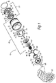
FIG. 1 is an exploded view illustrating an embodiment of a switchable exhale system in accordance with the present disclosure. -
FIG. 2 is cross-section view of an embodiment of a switchable exhale system in accordance with the present disclosure in an inactive configuration. -
FIG. 3 is a cross-section view of the switchable exhale system shown inFIG. 2 in an active configuration. -
FIG. 4 is a cross-section view of an alternative embodiment of a switchable exhale system in accordance with the present disclosure in an inactive configuration. -
FIG. 5 is cross-section view of the alternative embodiment of the switchable exhale system shown inFIG. 4 in an active configuration. - Referring to
FIGS. 1-3 , a switchable exhale filter system 10 (hereinafter "thesystem 10"), is indicated generally at 10. For the sake of convenience and clarity, terms such as "front," "rear," "top," "bottom," "up," "down," "inwardly," "outwardly," "downstream," "upstream," "lateral," and "longitudinal" will be used herein to describe the relative placement and orientation of the various components of thesystem 10, all with respect to the geometry and orientation of the exemplary embodiment of thesystem 10 as it appears inFIGS. 2 and 3 . Particularly, the terms "front," "forward," and "downstream" will be used to indicate a position nearer the left side ofFIGS. 2 and 3 , and the terms "rear," "rearward," and "upstream" will be used to indicate a position nearer the right side ofFIGS. 2 and 3 . Said terminology will include the words specifically mentioned, derivatives thereof, and words of similar import. - It will be appreciated that the
system 10 may be embodied as a removable cartridge assembly, or it may be a built-in feature of a respirator. - The
system 10 may include amain housing 12, anAPR valve assembly 14, aSCBA valve assembly 16 and anouter cover 18. The components of thesystem 10 may be formed of various metallic and polymeric materials that will be familiar to those of ordinary skill in the art. - The
main housing 12 of the system may be a generally cylindrical body defining anupstream chamber 20 and adownstream chamber 22 that are separated by apartition 24. Thepartition 24 may comprise atransverse member 26 formed by a plurality ofspokes 28 that extend radially inwardly from themember 26 to acentral hub 30. Theflange 26 may have a plurality of central openings 27 (seen inFIG. 1 ) formed between the plurality of spokes for allowing air to pass through theflange 26 to act on the SCBA valve. Theflange 26 may also have a plurality ofperipheral openings 29 that may act as bypass channels for the SCBA valve, as will be described in greater detail later. Thetransverse member 26 may further include an intermediateannular rim 32 that, as will be described in greater detail later, serves as a seat for theSCBA valve assembly 16. Theperipheral openings 29 may be disposed between theannular rim 32 and the inner surface of themain housing 12 so that they are not sealed by the SCBA valve. Thehub 30 may further include acentral channel 34 extending therethrough for holding aretaining pin 36 as further described below. - The
APR valve assembly 14 may include avalve seat member 38 and adisc member 40. Thevalve seat member 38 may be defined by a substantiallyannular body 42 joined by a plurality ofspokes 44 to acentral hub 46. Thespokes 44 may define a plurality of ventilation slits orapertures 48 therebetween for allowing air to pass through thevalve seat 38. Thevalve seat member 38 may include anannular rim 39 that serves as a seat for thedisc member 40. Thehub 46 may be a substantially cylindrical member having a forwardly extending boss or catchpin 50. Thevalve seat member 38 may be attached to the rear end of themain housing 12, thereby capping or closing off theupstream chamber 20 as shown inFIGS. 2 and 3 . Thevalve seat 38 may be attached to the rear end of themain housing 12 by snap fit, friction fit, threaded engagement, mechanical fasteners, or adhesives. - The
disc member 40 may be a standard flap or diaphragm valve disc composed of a resilient material, such as silicone rubber or other appropriate elastomeric material. Particularly, thevalve disc 40 may include a centralcylindrical boss 52 that is integral with an annular body portion 54 having aperipheral region 56 configured to seal against thevalve seat member 38. Arecess 58 may be formed in the rear of theboss 52 to define a cavity or catch. The head of thecatch pin 50 of thevalve seat member 38 may fit within therecess 58 to hold the two pieces together. The center of thedisc member 40 may thereby be securely "clipped" to thevalve seat member 38, so that theperipheral region 56 of the disc member is held in sealing engagement with theannular rim 39 of the valve seat member. - The
disc member 40 may be configured so that when a first pressure is applied to one side of the disc member (e.g., the pressure of a user's exhaled breath), the disc member deflects away from theannular rim 39, enabling air to pass around the disc member. When the first pressure is removed, thedisc member 40 returns to its original position, sealed against theannular rim 39, thereby preventing air from returning in a reverse direction through theAPR valve assembly 14. In one non-limiting exemplary embodiment, the first pressure may be about 0.1 mbar to about 3 mbar. - In the illustrated embodiment, an O-
ring 60 or other resilient sealing member may be provided on or adjacent to thevalve seat member 38 to provide a secure, airtight seal with a respirator mask (not shown) in which thesystem 10 is disposed. - The
SCBA valve assembly 16 of thesystem 10 includes abypass member 62, and may include aSCBA valve disc 64, avalve spring plate 66, and avalve spring 68. Also provided are a retainingmember 70, a retainingspring 72, and anactuator 74, all of which fit substantially within thedownstream chamber 22 of themain housing 12, as can be seen inFIGS. 2 and 3 . - As can best be seen in
FIG. 1 , thebypass member 62 of the positiveSCBA valve assembly 16 may be a substantially annular body having a plurality ofcatch arms 76 and a pair of diametrically opposedaxial displacement cams 78 extending from a front edge thereof. Eachcatch arm 76 may terminate in a hook-shapedcatch 80. Thebypass member 62 may further include several pairs of receivingarms 82 extending from a front edge thereof, wherein each pair of receiving arms defines anintermediate receiving channel 84 for accepting thefirst arms 86 of theretainer 70 as will be described below. - The
retainer 70 may include a substantially annularcentral hub 88 having a plurality offirst arms 86 extending radially outwardly therefrom. Eachfirst arm 86 may have an L-shapedretaining arm 90 extending forwardly from an outermost end of the associatedfirst arm 86. Theretainer 70 may be positioned with respect to thebypass member 62 so that thefirst arms 86 are seated within theintermediate receiving channels 84 of the bypass member, and so thefirst arms 86 extend beyond theretainer 70. The tips of the retainingarms 90 may abut and engage a front edge of the main housing 12 (FIG. 2 ), thereby constrain theretainer 70. - The retaining
spring 72 may be a conventional coil spring disposed between thebypass member 62 and theretainer 70. That is, a first end of the retainingspring 72 may engage thecatches 80 of thecatch arms 76 and a second end of the retainingspring 72 may engage the front surfaces of thefirst arms 86. The retainingspring 72 is thus held in compression and biases thebypass member 62 and theretainer 70 together. - As will be described in greater detail later, the
system 10 uses a cam-type action in which thebypass member 62 seals off a bypass around theSCBA valve assembly 16 to place thesystem 10 into an SCBA mode. Thereafter, when an activatinglever 108 is adjusted to an inactive position, the retainingspring 72 functions to return thebypass member 62 to the inactive position, opening the bypass around theSCBA valve assembly 16 and placing thesystem 10 into an APR mode. - The
SCBA valve disc 64 may be similar to theAPR valve disc 40 described above and may be a standard flap or diaphragm valve disc composed of a resilient material, such as silicone rubber or other appropriate material. Particularly, thevalve disc 64 may include a centralcylindrical boss 92 that is integral with anannular body portion 94 having aperipheral seal region 96. Theperipheral seal region 96 is thus configured to seal against theannular rim 32 of thepartition 24. Arecess 98 may be formed in the rear of theboss 92 to define a cavity or catch. The head of analignment pin 36 that is securely mounted within theaperture 34 of thehub 30 of thepartition 24 may fit within therecess 98 and may be held therein by frictional engagement. Thevalve disc 64 may thereby be securely "clipped" to thealignment pin 36, thus securing thevalve disc 64 in axial alignment with thepartition 24. Positioned thusly, thevalve disc 64 covers the entire central portion of thepartition 24, including thespokes 28 and apertures of thepartition 24, and seals against theannular rim 32 of the partition. - The
valve spring plate 66 may be a cup-shaped member having a rear surface with a contour that is substantially similar to the contour of the front surface of thevalve disc 64. Thespring plate 66 may be positioned in abutting relationship with thevalve disc 64, and may have acentral aperture 100 formed therethrough for receiving theboss 92 of thevalve disc 64 to secure thespring plate 66 in axial alignment with thevalve disc 64. - The
valve spring 68 may be a conventional coil spring positioned between theretainer 70 and thespring plate 66. Particularly, the forward extent of thevalve spring 68 may be seated against anannular shoulder 102 defined by thehub 88 of theretainer 70 and the rear extent of thevalve spring 68 may be seated against an annular shoulder 104 (FIG. 2 ) formed in the front surface of thespring plate 66. Positioned thusly, thecompressed valve spring 68 biases thespring plate 66 and thevalve disc 64 rearward, thereby holding the periphery of thevalve disc 64 in firm engagement with theannular rim 32 of thepartition 24 and forming a seal therebetween. The opening pressure of the SCBA valve assembly 16 (which may be referred to as a "second pressure" as compared to the "first pressure" which represents the opening pressure of the APR valve) may thus be adjusted through careful selection of the spring constant of thevalve spring 68. In one embodiment, thevalve spring 68 is selected to provide an opening pressure of theSCBA valve assembly 16 which is greater than a cracking pressure of a demand valve for a compressed air supply (not shown) when the respirator operates in a mode utilizing a compressed air supply, as will be described in greater detail below. The opening pressure of theSCBA valve assembly 16 is greater than the opening pressure of theAPR valve assembly 14. In one non-limiting exemplary embodiment, this opening pressure of theSCBA valve assembly 16 may be from about 3.5 mbar to about 6.5 mbar. - The
actuator member 74, which is best viewed inFIG. 1 , comprises acircular body 105 having acentral opening 106 for receiving a mounting shaft (not within view) that extends rearwardly from thecover 18. Anactuation lever 108 may extend radially outward from thecircular body 105 through an opening in the cover to allow a user to rotate theactuator 74. A plurality ofcam followers 110 may extend rearwardly from thecircular body 105 and comprise curved cam follower surfaces that are configured to engage thecams 78 of thebypass member 62 so that as theactuator member 74 is rotated in a first direction thebypass member 62 is moved axially toward thepartition 24 of themain housing 12, and as theactuator member 74 is rotated in a second direction thebypass member 62 is moved axially away from the partition. - Thus, in a first position (shown in
FIG. 2 ), thebypass member 62 is positioned away from thepartition 24 such that the rear extent of thebypass member 62 does not block theperipheral openings 29 in thepartition 24. As such, exhaled air is allowed to travel through theperipheral openings 29, bypassing theSCBA valve assembly 16, so that only theAPR valve assembly 14 is "in line." This is referred to as the "APR" mode, and the air flow in this mode is shown by the arrows illustrated inFIG. 2 . To configure thesystem 10 into the "SCBA" mode (shown inFIG. 3 ), theactuator member 74 is rotated so that thecam followers 110 engage thecams 78 of thebypass member 70, pushing the bypass member against thepartition 24 of themain housing 12, and sealing off theperipheral openings 29 in the partition. As such, exhaled air is prevented from bypassing theSCBA valve assembly 16, and instead the air is forced through thecentral openings 27 of thepartition 24 so that it acts against theSCBA valve disc 64. Air flow in this mode is shown by the arrows illustrated inFIG. 3 . - The
system 10 of the present disclosure is therefore operable in two different modes: an APR mode and a SCBA mode. As noted, to operate thesystem 10 in the APR mode, theactuation lever 108 is rotated so that thebypass member 62 assumes the position shown inFIG. 2 . Configured thusly, when air pressure inside the mask is negative during inhalation by a user, theAPR valve disc 40 is forced closed and air may only enter the mask through an air purification element (i.e., a filter) located upstream of theAPR valve disc 40. When the user exhales, the exhalation pressure inside the mask overcomes the opening pressure (i.e., the first pressure) of theAPR valve disc 40, thereby opening the APR valve and allowing the air into theupstream chamber 20 of themain housing 12. Since theperipheral openings 29 in thepartition 24 are not blocked by thebypass member 62, the exhaled air passes freely through the perforations, bypassing the closedSCBA valve disc 64, and is expelled through thecover 18 of thesystem 10. The user is therefore able to inhale purified air and exhale freely as with a conventional APR unit. - To operate the
system 10 in the SCBA mode, the user rotates theactuation lever 108 so that thebypass member 62 engages thepartition 24 as shown inFIG. 3 . In this mode, a positive pressure (below that of the opening pressure of the SCBA valve 16) can be maintained within the mask to prevent ingress of hazardous gases during use. Since, in this mode, thebypass member 62 has been moved to block the openings in thepartition flange 26, exhaled air is not allowed to bypass theSCBA valve disc 64 and is instead forced to pass through thecentral openings 27 in thepartition 24 and to confront theSCBA valve disc 64. During exhalation, the combined pressure of the compressed air and the exhaled air is sufficient to overcome the opening pressure of theSCBA valve disc 64. The SCBA valve disc therefore opens during exhalation and allows the exhaled air (and the compressed air) to flow into thedownstream chamber 22 of themain housing 12 and exit through thecover 18. The user is therefore able inhale purified air supplied by the compressed air source and to exhale freely as with a conventional SCBA unit. Moreover, the positive air pressure within the mask prevents external air from entering the mask while theSCBA pressure valve 64 prevents air in the mask from freely escaping from thesystem 10. - It will be appreciated that many alternative mechanical configurations of the
system 10 may be implemented for providing similar functionality as that described above. - Fundamentally, any such configuration should feature an APR valve having a first opening pressure and a SCBA valve having a second opening pressure that is greater than the first opening pressure, wherein a user can select operation of the system in either an APR mode or a SCBA mode by selectively engaging a set of bypass channels. Such selection can be manual, or it can be automated.
- An exemplary alternative embodiment of a
system 200 in accordance with present disclosure is illustrated inFIGS. 4 and 5 , wherein arotatable bypass member 202 is disposed within ahousing member 204. The system includes anintermediate partition member 206 having a plurality of openings (not shown) through which air is movable to contact aSCBA valve assembly 208. Thesystem 200 also includes anAPR valve assembly 210 similar to the APR valve assembly described in relation to the embodiment ofFIGS. 1-3 . Therotatable bypass member 202 includes a plurality ofopenings 212 in a wall thereof. In addition, a plurality ofopenings 214 are formed between thehousing member 204 and theintermediate partition member 206. In a first configuration (the "APR" mode, shown inFIG.3 ), therotatable bypass member 202 is positioned so that theopenings 212 of the bypass member are aligned with theopenings 214 formed between the housing member and the intermediate partition member, thus enabling exhaled air to bypass theSCBA valve assembly 208. The air flow pattern for this mode is shown by the arrows inFIG. 3 . To configure thesystem 200 into SCBA mode (shown inFIG. 4 ), therotatable bypass member 202 is rotated so that theopenings 212 are not aligned with theopenings 214 formed between the housing member and the intermediate partition member, thus blocking theopenings 214 and forcing exhaled air to engage theSCBA valve assembly 208. - As with the previous embodiment, the
APR valve assembly 210 may have an opening pressure that is lower than an opening pressure of theSCBA valve assembly 208. - This disclosed
systems
Claims (11)
- A configurable exhale system (10) for a respirator, the system comprising:a housing (12) having a chamber (20);a first valve assembly (14) disposed within the chamber (20) and configured to prevent air from flowing through the first valve assembly (14) when an air pressure differential between an upstream side and a downstream side of the first valve assembly (14) is below a first opening pressure; anda second valve assembly (16) disposed within the chamber (20) in fluid communication with the first valve assembly (14), the second valve assembly (16) configured to prevent air from flowing through the second valve assembly (16) when an air pressure differential between an upstream side and a downstream side of the second valve assembly (16) is below a second opening pressure, where the second opening pressure is greater than the first opening pressure;at least one bypass opening (29) positioned adjacent the second valve assembly (16), the at least one bypass opening (29) configured to enable air to bypass the second valve assembly (16); anda bypass member (62) positioned adjacent the at least one bypass opening (29), the bypass member (62) movable between first and second positions, wherein in the first position the bypass member (62) blocks the at least one bypass opening (29), and wherein in the in the second position the bypass member (62) does not block the at least one bypass opening (29) such that air can bypass the closed second valve assembly (16).
- A configurable exhale system of claim 1, wherein moving the bypass member (62) between the first and second positions comprises axial movement of the bypass member (62).
- A configurable exhale system of claim 1, wherein moving the bypass member (62) between the first and second positions comprises rotational movement of the bypass member (62).
- A configurable exhale system of claim 1, wherein the system comprises a removable cartridge.
- A configurable exhale system of claim 1, wherein the system comprises a built-in feature of a respirator.
- A configurable exhale system of claim 1, wherein moving the bypass member (62) between the first and second positions is initiated manually by a user.
- A method for providing a switchable exhale filter system for a respirator, the method comprising:providing a housing (10) having a first (14) and second (16) valve assemblies in fluid communication with each other; the first valve assembly (14) configured to prevent air from flowing through the first valve assembly (14) when an air pressure differential between an upstream side and a downstream side of the first valve assembly (14) is below a first pressure; the second valve assembly (16) configured to prevent air from flowing through the second valve assembly (16) when an air pressure differential between an upstream side and a downstream side of the second valve assembly (16) is below a second pressure; the second pressure being greater than the first pressure;providing at least one opening (29) adjacent the second valve assembly (16) for allowing air to bypass the second valve assembly (16);providing a bypass member (62) adjacent the at least one opening (29); andmoving the bypass member (62) between first and second positions, wherein in the first position the bypass member (62) blocks the opening (29), and wherein in the second position the bypass member (62) does not block the opening (29) so as to allow air to flow through the opening (29) to bypass the closed second valve assembly (16)
- A method of claim 7, wherein moving the bypass member (62) between the first and second position comprises one of moving the bypass member axially and rotating the bypass member.
- A method of claim 7, wherein the system comprises a removable cartridge.
- A method of claim 7, wherein the system comprises a built-in feature of a respirator.
- A method of claim 7, wherein moving the bypass member (62) between first and second positions is initiated manually by a user.
Priority Applications (1)
| Application Number | Priority Date | Filing Date | Title |
|---|---|---|---|
| PL13748362T PL2879763T3 (en) | 2012-08-06 | 2013-07-24 | Switchable exhale filter system |
Applications Claiming Priority (2)
| Application Number | Priority Date | Filing Date | Title |
|---|---|---|---|
| GBGB1214088.5A GB201214088D0 (en) | 2012-08-06 | 2012-08-06 | Switchable exhale filter system |
| PCT/GB2013/051974 WO2014023933A2 (en) | 2012-08-06 | 2013-07-24 | Switchable exhale filter system |
Publications (2)
| Publication Number | Publication Date |
|---|---|
| EP2879763A2 EP2879763A2 (en) | 2015-06-10 |
| EP2879763B1 true EP2879763B1 (en) | 2018-10-31 |
Family
ID=46935036
Family Applications (1)
| Application Number | Title | Priority Date | Filing Date |
|---|---|---|---|
| EP13748362.4A Active EP2879763B1 (en) | 2012-08-06 | 2013-07-24 | Switchable exhale filter system |
Country Status (15)
| Country | Link |
|---|---|
| US (1) | US10220224B2 (en) |
| EP (1) | EP2879763B1 (en) |
| JP (2) | JP2015529497A (en) |
| CN (1) | CN104661710A (en) |
| AU (1) | AU2013301413B9 (en) |
| BR (1) | BR112015002509A8 (en) |
| CA (1) | CA2881350A1 (en) |
| EA (1) | EA028934B1 (en) |
| ES (1) | ES2708206T3 (en) |
| GB (1) | GB201214088D0 (en) |
| IL (1) | IL237026B (en) |
| PL (1) | PL2879763T3 (en) |
| SG (1) | SG11201500893PA (en) |
| WO (1) | WO2014023933A2 (en) |
| ZA (1) | ZA201500873B (en) |
Families Citing this family (24)
| Publication number | Priority date | Publication date | Assignee | Title |
|---|---|---|---|---|
| GB201214088D0 (en) * | 2012-08-06 | 2012-09-19 | Scott Health & Safety Ltd | Switchable exhale filter system |
| WO2015027390A1 (en) * | 2013-08-27 | 2015-03-05 | Honeywell International Inc. | Fresh air port mechanism for facepiece used on self-contained open-circuit compressed air breathing apparatus |
| EP4364818B1 (en) | 2016-03-28 | 2025-10-29 | 3M Innovative Properties Company | Respiratory protection device |
| GB201609168D0 (en) | 2016-05-25 | 2016-07-06 | 3M Innovative Properties Co | Exhaust valve shroud for a personal protection respiratory device |
| CN107875534A (en) * | 2017-11-07 | 2018-04-06 | 山西新华化工有限责任公司 | Breathing mask positive/negative-pressure switching mechanism |
| US10967206B2 (en) * | 2018-01-16 | 2021-04-06 | Makrite Industries Inc. | Valve structure for respirator |
| US10322312B1 (en) * | 2018-06-01 | 2019-06-18 | TrainingMask L.L.C. | Resistance and filtration breathing device |
| KR102494579B1 (en) | 2020-06-05 | 2023-02-02 | 엘지전자 주식회사 | Mask apparatus |
| KR102309925B1 (en) | 2020-06-05 | 2021-10-08 | 엘지전자 주식회사 | Mask apparatus |
| KR102408364B1 (en) | 2020-06-05 | 2022-06-13 | 엘지전자 주식회사 | Mask apparatus |
| KR102452392B1 (en) | 2020-06-05 | 2022-10-11 | 엘지전자 주식회사 | Mask apparatus |
| KR102307772B1 (en) | 2020-06-05 | 2021-10-05 | 엘지전자 주식회사 | Mask apparatus |
| KR102367071B1 (en) | 2020-06-05 | 2022-02-25 | 엘지전자 주식회사 | Mask apparatus |
| KR102256713B1 (en) | 2020-06-05 | 2021-05-27 | 엘지전자 주식회사 | Mask apparatus and controlling method thereof |
| KR102436838B1 (en) | 2020-06-30 | 2022-08-26 | 엘지전자 주식회사 | Mask apparatus and controlling method thereof |
| KR102418745B1 (en) * | 2020-06-30 | 2022-07-11 | 엘지전자 주식회사 | Mask apparatus |
| KR102460798B1 (en) | 2020-06-30 | 2022-10-31 | 엘지전자 주식회사 | Mask apparatus |
| KR102458618B1 (en) | 2020-07-17 | 2022-10-25 | 엘지전자 주식회사 | Mask apparatus and controlling method thereof |
| KR102294479B1 (en) | 2020-08-28 | 2021-08-27 | 엘지전자 주식회사 | Sterilizing case |
| AU2022263549B2 (en) * | 2021-07-19 | 2023-02-16 | Commonwealth Scientific And Industrial Research Organisation | Robot appendage force dampening |
| CA3239009A1 (en) * | 2021-12-09 | 2023-06-15 | Samuel WHYMAN | Breathing apparatus system |
| US12390670B2 (en) * | 2022-01-28 | 2025-08-19 | Moldex-Metric, Inc. | Dual mode respirator |
| WO2023250344A1 (en) * | 2022-06-21 | 2023-12-28 | Schumacher James B | Air filtration mask exhalation valve with on/off capability |
| CN115553517B (en) * | 2022-09-30 | 2025-09-23 | 日照市气象局 | A mask for filtering and disinfecting airborne droplets, viruses and bacteria |
Family Cites Families (13)
| Publication number | Priority date | Publication date | Assignee | Title |
|---|---|---|---|---|
| US2406888A (en) * | 1944-06-06 | 1946-09-03 | Scott Aviation Corp | Breathing apparatus |
| US2985169A (en) * | 1957-09-09 | 1961-05-23 | Scott Aviation Corp | Exhalation-valve unit for a breathing mask |
| US3933171A (en) * | 1974-04-09 | 1976-01-20 | Airco, Inc. | Anesthesia breathing circuit with positive end expiratory pressure valve |
| US5002050A (en) * | 1986-09-17 | 1991-03-26 | Mcginnis Gerald E | Medical gas flow control valve, system and method |
| AUPO422996A0 (en) | 1996-12-16 | 1997-01-16 | Resmed Limited | A valve |
| US20040182394A1 (en) * | 2003-03-21 | 2004-09-23 | Alvey Jeffrey Arthur | Powered air purifying respirator system and self contained breathing apparatus |
| WO2004093997A1 (en) | 2003-03-21 | 2004-11-04 | Interspiro Ab | Powered air purifying respirator system and breathing apparatus |
| GB0406288D0 (en) * | 2004-03-19 | 2004-04-21 | Scott Health & Safety Ltd | Respirators |
| DE602005020036D1 (en) | 2004-09-27 | 2010-04-29 | Avon Protection Systems Inc | EXHIBITION UNIT OF A VENTILATOR |
| JP4791214B2 (en) * | 2006-03-10 | 2011-10-12 | エア・ウォーター防災株式会社 | Respiratory organ |
| US7762252B2 (en) * | 2006-04-26 | 2010-07-27 | Mine Safety Appliances Company | Devices, systems and methods for operation of breathing apparatuses in multiple modes |
| GB2470199B (en) * | 2009-05-12 | 2013-08-14 | Scott Health & Safety Ltd | Mask for breathing apparatus |
| GB201214088D0 (en) * | 2012-08-06 | 2012-09-19 | Scott Health & Safety Ltd | Switchable exhale filter system |
-
2012
- 2012-08-06 GB GBGB1214088.5A patent/GB201214088D0/en not_active Ceased
-
2013
- 2013-07-24 EA EA201590333A patent/EA028934B1/en not_active IP Right Cessation
- 2013-07-24 ES ES13748362T patent/ES2708206T3/en active Active
- 2013-07-24 SG SG11201500893PA patent/SG11201500893PA/en unknown
- 2013-07-24 JP JP2015525935A patent/JP2015529497A/en not_active Ceased
- 2013-07-24 AU AU2013301413A patent/AU2013301413B9/en not_active Ceased
- 2013-07-24 EP EP13748362.4A patent/EP2879763B1/en active Active
- 2013-07-24 PL PL13748362T patent/PL2879763T3/en unknown
- 2013-07-24 CA CA2881350A patent/CA2881350A1/en not_active Abandoned
- 2013-07-24 WO PCT/GB2013/051974 patent/WO2014023933A2/en not_active Ceased
- 2013-07-24 BR BR112015002509A patent/BR112015002509A8/en active Search and Examination
- 2013-07-24 CN CN201380047430.2A patent/CN104661710A/en active Pending
-
2015
- 2015-02-01 IL IL237026A patent/IL237026B/en active IP Right Grant
- 2015-02-06 US US14/615,829 patent/US10220224B2/en active Active
- 2015-02-06 ZA ZA2015/00873A patent/ZA201500873B/en unknown
-
2018
- 2018-03-20 JP JP2018052906A patent/JP2018126535A/en active Pending
Non-Patent Citations (1)
| Title |
|---|
| None * |
Also Published As
| Publication number | Publication date |
|---|---|
| EA201590333A1 (en) | 2015-07-30 |
| JP2015529497A (en) | 2015-10-08 |
| BR112015002509A8 (en) | 2018-06-05 |
| PL2879763T3 (en) | 2019-08-30 |
| IL237026B (en) | 2019-01-31 |
| GB201214088D0 (en) | 2012-09-19 |
| CA2881350A1 (en) | 2014-02-13 |
| AU2013301413B9 (en) | 2017-10-05 |
| BR112015002509A2 (en) | 2018-05-15 |
| ES2708206T3 (en) | 2019-04-09 |
| WO2014023933A3 (en) | 2014-11-13 |
| ZA201500873B (en) | 2016-10-26 |
| WO2014023933A2 (en) | 2014-02-13 |
| AU2013301413A1 (en) | 2015-02-26 |
| CN104661710A (en) | 2015-05-27 |
| US20150151143A1 (en) | 2015-06-04 |
| AU2013301413B2 (en) | 2017-05-25 |
| EP2879763A2 (en) | 2015-06-10 |
| EA028934B1 (en) | 2018-01-31 |
| US10220224B2 (en) | 2019-03-05 |
| SG11201500893PA (en) | 2015-04-29 |
| JP2018126535A (en) | 2018-08-16 |
Similar Documents
| Publication | Publication Date | Title |
|---|---|---|
| US10220224B2 (en) | Switchable exhale filter system | |
| US6860267B2 (en) | Self-sealing filter connection and gas mask filter assembly incorporating the same | |
| CA2581501C (en) | Respirator exhalation unit | |
| EP2588201B1 (en) | Facepiece with open port | |
| AU2002303617B2 (en) | Respirator valve | |
| US9498657B2 (en) | Diaphragm | |
| AU2002303617A1 (en) | Respirator valve | |
| US20120325221A1 (en) | Lightweight Respirator | |
| US11040226B2 (en) | Serviceable cartridge assembly for respirator exhalation unit | |
| CA2559635A1 (en) | Respirators | |
| US11883695B2 (en) | Respirator mask with air-saver switch | |
| HK1135055A (en) | Respirator exhalation unit |
Legal Events
| Date | Code | Title | Description |
|---|---|---|---|
| PUAI | Public reference made under article 153(3) epc to a published international application that has entered the european phase |
Free format text: ORIGINAL CODE: 0009012 |
|
| 17P | Request for examination filed |
Effective date: 20150203 |
|
| AK | Designated contracting states |
Kind code of ref document: A2 Designated state(s): AL AT BE BG CH CY CZ DE DK EE ES FI FR GB GR HR HU IE IS IT LI LT LU LV MC MK MT NL NO PL PT RO RS SE SI SK SM TR |
|
| AX | Request for extension of the european patent |
Extension state: BA ME |
|
| DAX | Request for extension of the european patent (deleted) | ||
| STAA | Information on the status of an ep patent application or granted ep patent |
Free format text: STATUS: EXAMINATION IS IN PROGRESS |
|
| 17Q | First examination report despatched |
Effective date: 20180126 |
|
| GRAP | Despatch of communication of intention to grant a patent |
Free format text: ORIGINAL CODE: EPIDOSNIGR1 |
|
| STAA | Information on the status of an ep patent application or granted ep patent |
Free format text: STATUS: GRANT OF PATENT IS INTENDED |
|
| INTG | Intention to grant announced |
Effective date: 20180530 |
|
| GRAS | Grant fee paid |
Free format text: ORIGINAL CODE: EPIDOSNIGR3 |
|
| GRAA | (expected) grant |
Free format text: ORIGINAL CODE: 0009210 |
|
| STAA | Information on the status of an ep patent application or granted ep patent |
Free format text: STATUS: THE PATENT HAS BEEN GRANTED |
|
| AK | Designated contracting states |
Kind code of ref document: B1 Designated state(s): AL AT BE BG CH CY CZ DE DK EE ES FI FR GB GR HR HU IE IS IT LI LT LU LV MC MK MT NL NO PL PT RO RS SE SI SK SM TR |
|
| REG | Reference to a national code |
Ref country code: CH Ref legal event code: EP Ref country code: GB Ref legal event code: FG4D |
|
| REG | Reference to a national code |
Ref country code: AT Ref legal event code: REF Ref document number: 1058685 Country of ref document: AT Kind code of ref document: T Effective date: 20181115 |
|
| REG | Reference to a national code |
Ref country code: IE Ref legal event code: FG4D |
|
| REG | Reference to a national code |
Ref country code: DE Ref legal event code: R096 Ref document number: 602013045967 Country of ref document: DE |
|
| REG | Reference to a national code |
Ref country code: NL Ref legal event code: MP Effective date: 20181031 |
|
| REG | Reference to a national code |
Ref country code: LT Ref legal event code: MG4D Ref country code: SE Ref legal event code: TRGR |
|
| REG | Reference to a national code |
Ref country code: ES Ref legal event code: FG2A Ref document number: 2708206 Country of ref document: ES Kind code of ref document: T3 Effective date: 20190409 |
|
| REG | Reference to a national code |
Ref country code: AT Ref legal event code: MK05 Ref document number: 1058685 Country of ref document: AT Kind code of ref document: T Effective date: 20181031 |
|
| PG25 | Lapsed in a contracting state [announced via postgrant information from national office to epo] |
Ref country code: HR Free format text: LAPSE BECAUSE OF FAILURE TO SUBMIT A TRANSLATION OF THE DESCRIPTION OR TO PAY THE FEE WITHIN THE PRESCRIBED TIME-LIMIT Effective date: 20181031 Ref country code: AT Free format text: LAPSE BECAUSE OF FAILURE TO SUBMIT A TRANSLATION OF THE DESCRIPTION OR TO PAY THE FEE WITHIN THE PRESCRIBED TIME-LIMIT Effective date: 20181031 Ref country code: NO Free format text: LAPSE BECAUSE OF FAILURE TO SUBMIT A TRANSLATION OF THE DESCRIPTION OR TO PAY THE FEE WITHIN THE PRESCRIBED TIME-LIMIT Effective date: 20190131 Ref country code: LV Free format text: LAPSE BECAUSE OF FAILURE TO SUBMIT A TRANSLATION OF THE DESCRIPTION OR TO PAY THE FEE WITHIN THE PRESCRIBED TIME-LIMIT Effective date: 20181031 Ref country code: FI Free format text: LAPSE BECAUSE OF FAILURE TO SUBMIT A TRANSLATION OF THE DESCRIPTION OR TO PAY THE FEE WITHIN THE PRESCRIBED TIME-LIMIT Effective date: 20181031 Ref country code: IS Free format text: LAPSE BECAUSE OF FAILURE TO SUBMIT A TRANSLATION OF THE DESCRIPTION OR TO PAY THE FEE WITHIN THE PRESCRIBED TIME-LIMIT Effective date: 20190228 Ref country code: LT Free format text: LAPSE BECAUSE OF FAILURE TO SUBMIT A TRANSLATION OF THE DESCRIPTION OR TO PAY THE FEE WITHIN THE PRESCRIBED TIME-LIMIT Effective date: 20181031 Ref country code: BG Free format text: LAPSE BECAUSE OF FAILURE TO SUBMIT A TRANSLATION OF THE DESCRIPTION OR TO PAY THE FEE WITHIN THE PRESCRIBED TIME-LIMIT Effective date: 20190131 |
|
| PG25 | Lapsed in a contracting state [announced via postgrant information from national office to epo] |
Ref country code: PT Free format text: LAPSE BECAUSE OF FAILURE TO SUBMIT A TRANSLATION OF THE DESCRIPTION OR TO PAY THE FEE WITHIN THE PRESCRIBED TIME-LIMIT Effective date: 20190301 Ref country code: NL Free format text: LAPSE BECAUSE OF FAILURE TO SUBMIT A TRANSLATION OF THE DESCRIPTION OR TO PAY THE FEE WITHIN THE PRESCRIBED TIME-LIMIT Effective date: 20181031 Ref country code: AL Free format text: LAPSE BECAUSE OF FAILURE TO SUBMIT A TRANSLATION OF THE DESCRIPTION OR TO PAY THE FEE WITHIN THE PRESCRIBED TIME-LIMIT Effective date: 20181031 Ref country code: GR Free format text: LAPSE BECAUSE OF FAILURE TO SUBMIT A TRANSLATION OF THE DESCRIPTION OR TO PAY THE FEE WITHIN THE PRESCRIBED TIME-LIMIT Effective date: 20190201 Ref country code: SE Free format text: LAPSE BECAUSE OF FAILURE TO SUBMIT A TRANSLATION OF THE DESCRIPTION OR TO PAY THE FEE WITHIN THE PRESCRIBED TIME-LIMIT Effective date: 20181031 Ref country code: RS Free format text: LAPSE BECAUSE OF FAILURE TO SUBMIT A TRANSLATION OF THE DESCRIPTION OR TO PAY THE FEE WITHIN THE PRESCRIBED TIME-LIMIT Effective date: 20181031 |
|
| PG25 | Lapsed in a contracting state [announced via postgrant information from national office to epo] |
Ref country code: CZ Free format text: LAPSE BECAUSE OF FAILURE TO SUBMIT A TRANSLATION OF THE DESCRIPTION OR TO PAY THE FEE WITHIN THE PRESCRIBED TIME-LIMIT Effective date: 20181031 Ref country code: DK Free format text: LAPSE BECAUSE OF FAILURE TO SUBMIT A TRANSLATION OF THE DESCRIPTION OR TO PAY THE FEE WITHIN THE PRESCRIBED TIME-LIMIT Effective date: 20181031 |
|
| REG | Reference to a national code |
Ref country code: DE Ref legal event code: R097 Ref document number: 602013045967 Country of ref document: DE |
|
| PG25 | Lapsed in a contracting state [announced via postgrant information from national office to epo] |
Ref country code: RO Free format text: LAPSE BECAUSE OF FAILURE TO SUBMIT A TRANSLATION OF THE DESCRIPTION OR TO PAY THE FEE WITHIN THE PRESCRIBED TIME-LIMIT Effective date: 20181031 Ref country code: EE Free format text: LAPSE BECAUSE OF FAILURE TO SUBMIT A TRANSLATION OF THE DESCRIPTION OR TO PAY THE FEE WITHIN THE PRESCRIBED TIME-LIMIT Effective date: 20181031 Ref country code: SM Free format text: LAPSE BECAUSE OF FAILURE TO SUBMIT A TRANSLATION OF THE DESCRIPTION OR TO PAY THE FEE WITHIN THE PRESCRIBED TIME-LIMIT Effective date: 20181031 Ref country code: SK Free format text: LAPSE BECAUSE OF FAILURE TO SUBMIT A TRANSLATION OF THE DESCRIPTION OR TO PAY THE FEE WITHIN THE PRESCRIBED TIME-LIMIT Effective date: 20181031 |
|
| PLBE | No opposition filed within time limit |
Free format text: ORIGINAL CODE: 0009261 |
|
| STAA | Information on the status of an ep patent application or granted ep patent |
Free format text: STATUS: NO OPPOSITION FILED WITHIN TIME LIMIT |
|
| 26N | No opposition filed |
Effective date: 20190801 |
|
| PG25 | Lapsed in a contracting state [announced via postgrant information from national office to epo] |
Ref country code: SI Free format text: LAPSE BECAUSE OF FAILURE TO SUBMIT A TRANSLATION OF THE DESCRIPTION OR TO PAY THE FEE WITHIN THE PRESCRIBED TIME-LIMIT Effective date: 20181031 |
|
| PG25 | Lapsed in a contracting state [announced via postgrant information from national office to epo] |
Ref country code: MC Free format text: LAPSE BECAUSE OF FAILURE TO SUBMIT A TRANSLATION OF THE DESCRIPTION OR TO PAY THE FEE WITHIN THE PRESCRIBED TIME-LIMIT Effective date: 20181031 |
|
| REG | Reference to a national code |
Ref country code: CH Ref legal event code: PL |
|
| REG | Reference to a national code |
Ref country code: SE Ref legal event code: EUG |
|
| PG25 | Lapsed in a contracting state [announced via postgrant information from national office to epo] |
Ref country code: TR Free format text: LAPSE BECAUSE OF FAILURE TO SUBMIT A TRANSLATION OF THE DESCRIPTION OR TO PAY THE FEE WITHIN THE PRESCRIBED TIME-LIMIT Effective date: 20181031 |
|
| REG | Reference to a national code |
Ref country code: BE Ref legal event code: MM Effective date: 20190731 |
|
| PG25 | Lapsed in a contracting state [announced via postgrant information from national office to epo] |
Ref country code: SE Free format text: LAPSE BECAUSE OF FAILURE TO SUBMIT A TRANSLATION OF THE DESCRIPTION OR TO PAY THE FEE WITHIN THE PRESCRIBED TIME-LIMIT Effective date: 20190725 |
|
| PG25 | Lapsed in a contracting state [announced via postgrant information from national office to epo] |
Ref country code: LU Free format text: LAPSE BECAUSE OF NON-PAYMENT OF DUE FEES Effective date: 20190724 Ref country code: BE Free format text: LAPSE BECAUSE OF NON-PAYMENT OF DUE FEES Effective date: 20190731 Ref country code: CH Free format text: LAPSE BECAUSE OF NON-PAYMENT OF DUE FEES Effective date: 20190731 Ref country code: LI Free format text: LAPSE BECAUSE OF NON-PAYMENT OF DUE FEES Effective date: 20190731 |
|
| PG25 | Lapsed in a contracting state [announced via postgrant information from national office to epo] |
Ref country code: IE Free format text: LAPSE BECAUSE OF NON-PAYMENT OF DUE FEES Effective date: 20190724 |
|
| PGFP | Annual fee paid to national office [announced via postgrant information from national office to epo] |
Ref country code: FR Payment date: 20200611 Year of fee payment: 8 |
|
| PG25 | Lapsed in a contracting state [announced via postgrant information from national office to epo] |
Ref country code: IT Free format text: LAPSE BECAUSE OF NON-PAYMENT OF DUE FEES Effective date: 20190724 |
|
| PG25 | Lapsed in a contracting state [announced via postgrant information from national office to epo] |
Ref country code: PL Free format text: LAPSE BECAUSE OF NON-PAYMENT OF DUE FEES Effective date: 20190724 |
|
| REG | Reference to a national code |
Ref country code: ES Ref legal event code: FD2A Effective date: 20201130 |
|
| PG25 | Lapsed in a contracting state [announced via postgrant information from national office to epo] |
Ref country code: ES Free format text: LAPSE BECAUSE OF NON-PAYMENT OF DUE FEES Effective date: 20190725 |
|
| PG25 | Lapsed in a contracting state [announced via postgrant information from national office to epo] |
Ref country code: CY Free format text: LAPSE BECAUSE OF FAILURE TO SUBMIT A TRANSLATION OF THE DESCRIPTION OR TO PAY THE FEE WITHIN THE PRESCRIBED TIME-LIMIT Effective date: 20181031 |
|
| PG25 | Lapsed in a contracting state [announced via postgrant information from national office to epo] |
Ref country code: MT Free format text: LAPSE BECAUSE OF FAILURE TO SUBMIT A TRANSLATION OF THE DESCRIPTION OR TO PAY THE FEE WITHIN THE PRESCRIBED TIME-LIMIT Effective date: 20181031 Ref country code: HU Free format text: LAPSE BECAUSE OF FAILURE TO SUBMIT A TRANSLATION OF THE DESCRIPTION OR TO PAY THE FEE WITHIN THE PRESCRIBED TIME-LIMIT; INVALID AB INITIO Effective date: 20130724 |
|
| PG25 | Lapsed in a contracting state [announced via postgrant information from national office to epo] |
Ref country code: FR Free format text: LAPSE BECAUSE OF NON-PAYMENT OF DUE FEES Effective date: 20210731 |
|
| PG25 | Lapsed in a contracting state [announced via postgrant information from national office to epo] |
Ref country code: MK Free format text: LAPSE BECAUSE OF FAILURE TO SUBMIT A TRANSLATION OF THE DESCRIPTION OR TO PAY THE FEE WITHIN THE PRESCRIBED TIME-LIMIT Effective date: 20181031 |
|
| P01 | Opt-out of the competence of the unified patent court (upc) registered |
Effective date: 20230530 |
|
| PGFP | Annual fee paid to national office [announced via postgrant information from national office to epo] |
Ref country code: GB Payment date: 20250619 Year of fee payment: 13 |
|
| PGFP | Annual fee paid to national office [announced via postgrant information from national office to epo] |
Ref country code: DE Payment date: 20250620 Year of fee payment: 13 |