EP2879610B1 - Pelvic digitizer device with inertial sensor unit and method - Google Patents
Pelvic digitizer device with inertial sensor unit and method Download PDFInfo
- Publication number
- EP2879610B1 EP2879610B1 EP13825223.4A EP13825223A EP2879610B1 EP 2879610 B1 EP2879610 B1 EP 2879610B1 EP 13825223 A EP13825223 A EP 13825223A EP 2879610 B1 EP2879610 B1 EP 2879610B1
- Authority
- EP
- European Patent Office
- Prior art keywords
- sensor unit
- pelvic
- inertial sensor
- patient
- digitizer device
- Prior art date
- Legal status (The legal status is an assumption and is not a legal conclusion. Google has not performed a legal analysis and makes no representation as to the accuracy of the status listed.)
- Active
Links
Images


Classifications
-
- A—HUMAN NECESSITIES
- A61—MEDICAL OR VETERINARY SCIENCE; HYGIENE
- A61B—DIAGNOSIS; SURGERY; IDENTIFICATION
- A61B5/00—Measuring for diagnostic purposes; Identification of persons
- A61B5/103—Measuring devices for testing the shape, pattern, colour, size or movement of the body or parts thereof, for diagnostic purposes
- A61B5/107—Measuring physical dimensions, e.g. size of the entire body or parts thereof
- A61B5/1077—Measuring of profiles
-
- A—HUMAN NECESSITIES
- A61—MEDICAL OR VETERINARY SCIENCE; HYGIENE
- A61F—FILTERS IMPLANTABLE INTO BLOOD VESSELS; PROSTHESES; DEVICES PROVIDING PATENCY TO, OR PREVENTING COLLAPSING OF, TUBULAR STRUCTURES OF THE BODY, e.g. STENTS; ORTHOPAEDIC, NURSING OR CONTRACEPTIVE DEVICES; FOMENTATION; TREATMENT OR PROTECTION OF EYES OR EARS; BANDAGES, DRESSINGS OR ABSORBENT PADS; FIRST-AID KITS
- A61F2/00—Filters implantable into blood vessels; Prostheses, i.e. artificial substitutes or replacements for parts of the body; Appliances for connecting them with the body; Devices providing patency to, or preventing collapsing of, tubular structures of the body, e.g. stents
- A61F2/02—Prostheses implantable into the body
- A61F2/30—Joints
- A61F2/46—Special tools for implanting artificial joints
- A61F2/4603—Special tools for implanting artificial joints for insertion or extraction of endoprosthetic joints or of accessories thereof
- A61F2/4609—Special tools for implanting artificial joints for insertion or extraction of endoprosthetic joints or of accessories thereof of acetabular cups
-
- A—HUMAN NECESSITIES
- A61—MEDICAL OR VETERINARY SCIENCE; HYGIENE
- A61B—DIAGNOSIS; SURGERY; IDENTIFICATION
- A61B34/00—Computer-aided surgery; Manipulators or robots specially adapted for use in surgery
- A61B34/20—Surgical navigation systems; Devices for tracking or guiding surgical instruments, e.g. for frameless stereotaxis
- A61B2034/2046—Tracking techniques
- A61B2034/2048—Tracking techniques using an accelerometer or inertia sensor
-
- A—HUMAN NECESSITIES
- A61—MEDICAL OR VETERINARY SCIENCE; HYGIENE
- A61F—FILTERS IMPLANTABLE INTO BLOOD VESSELS; PROSTHESES; DEVICES PROVIDING PATENCY TO, OR PREVENTING COLLAPSING OF, TUBULAR STRUCTURES OF THE BODY, e.g. STENTS; ORTHOPAEDIC, NURSING OR CONTRACEPTIVE DEVICES; FOMENTATION; TREATMENT OR PROTECTION OF EYES OR EARS; BANDAGES, DRESSINGS OR ABSORBENT PADS; FIRST-AID KITS
- A61F2/00—Filters implantable into blood vessels; Prostheses, i.e. artificial substitutes or replacements for parts of the body; Appliances for connecting them with the body; Devices providing patency to, or preventing collapsing of, tubular structures of the body, e.g. stents
- A61F2/02—Prostheses implantable into the body
- A61F2/30—Joints
- A61F2/46—Special tools for implanting artificial joints
- A61F2/4657—Measuring instruments used for implanting artificial joints
- A61F2002/4668—Measuring instruments used for implanting artificial joints for measuring angles
Definitions
- the present application relates to computer-assisted surgery using inertial sensors, and more specifically to the creation of a frame of reference for a pelvis for subsequent navigation of tools using inertial sensors.
- the proposed system and method uses self-contained inertial sensors, which do not rely on signal transmission and immune to electromagnetic disturbances. Therefore, it is particularly suitable for the applications in the OR environment containing a large amount of equipment.
- WO 2010030809 discloses hip preparation systems and methods which can include a surgical orientation device.
- the hip preparation systems and methods can be used, for example, to orient the hip during the procedure, determine the orientation of an anatomical plane or planes, and orient a prosthetic component or components.
- a pelvic digitizer device as set out in claim 1.
- the device 10 is of the type used with an inertial sensor unit 11 mounted on a tool body 12.
- the inertial sensor unit 11 may be known as a sourceless sensor, a micro-electromechanical sensor unit (MEMS unit), and has any appropriate set of inertial sensors (e.g., accelerometers, gyroscope) to produce tracking data in at least three degrees of rotation (i.e., the orientation about a set of three axes is tracked) .
- the sensor unit 11 may be self enclosed in a pod that is connectable in an accurate and predetermined manner to the tool body 12 of the device 10.
- the tool body 12 has a tool end 20 in the shape of a cup 21.
- the cup 21 is shaped to match the shape of an acetabulum (e.g., a hemisphere or quasi-hemisphere), and the size of the cup 21 may be selected as a function of pre-operative imaging of the acetabulum, as will be described hereinafter.
- the cup 21 may be releasably connected to a shaft 22 of the tool body 12, such that a cup 21 of appropriate dimension may be selected.
- a stopper 23 is integral with the cup 21, and may have different configurations as is shown in Fig. 2 , including a pointy edge. Moreover, the stopper 23 may rotate relative to the shaft 22, to be turned to a desired orientation to contact bone landmarks.
- a handle 24 is located at an opposite end of the cup 21 on the shaft 22.
- the handle 24 is ergonomically configured to be handled by a user.
- a visual guide 25 is a rod that projects transversally from the handle 24. The visual guide 25 is used to visually guide the user in aligning the device 10 with the body of the patient.
- the visual guide 25 is a laser or LED light source that emits a visual line for guidance.
- a receptacle 26 is located at the end of the handle 24, and is configured to receive the sensor unit 11 in the accurate and predetermined manner.
- the sensor unit 11 may be built-in to the tool body 12.
- an orientation of the sensor unit 11 is preset relative to the tool body 12, such that tracking about at least one axis (one rotational degree of freedom) is known when the sensor unit 11 is initialized.
- the shaft 22 and the visual guide 25 lie in a plane of the device 10, and the preset orientation of the sensor unit 11 has its axis normal to the plane of the device 10.
- an axis of the sensor unit 11 will be normal to the plane of the device 10 in which the shaft 22 and the visual guide 25 (or light line produced thereby) lie.
- the sensor unit 11 may be equipped with visual interfaces to provide data to a user (e.g., LEDs of different colors, such as green and red), or may be connected to a computer-assisted surgery system to transmit the orientation data thereto.
- the transmission of data may be wireless, in any appropriate protocol (e.g., Bluetooth, ZigBee, etc).
- a method of using the device 10 to create a pelvic frame of reference (a.k.a., pelvic coordinate system) is set forth.
- the frontal plane of the pelvis of the patient is imaged using any appropriate type of imaging (e.g., X-ray), to obtain an image as in Fig. 4 .
- angle ⁇ may be obtained (shown as 40 degrees), as the acetabulum line, i.e., the line crossing portions of the rim of the acetabulum, relative to the medio-lateral axis (hereinafter ML axis).
- the ML axis may be the line that connects 2 antero-superior iliac spine (ASIS) points or connects the bottom of two teardrops of the pelvis, as shown in Fig. 4 .
- ASIS antero-superior iliac spine
- the cup size that fits the patient's native acetabulum may be evaluated.
- the next steps are performed intra-operatively, with the device 10 being equipped with a sensor unit 11 with preset orientation and the cup 21 dimensioned to match the pre-operative evaluated size.
- the device 10 being equipped with a sensor unit 11 with preset orientation and the cup 21 dimensioned to match the pre-operative evaluated size.
- the cup 21 of the device 10 is inserted in the native acetabulum before it is reamed.
- the stopper 23 is abutted against the rim of the acetabulum to ensure that the cup 21 is properly inserted in the acetabulum.
- the device 10 may be waggled back-and-forth in the patient's acetabulum, while keeping the instrument moving in the patient frontal plane. The waggle motion will be stopped by the stopper 23 on the modular cup 21.
- the stopper 23 points towards the patient's head, but may be configured and rotated to point toward the patient's feet, etc, as a matter of preference of the surgeon, considering the environing soft tissue.
- the stopper 23 can be adjustable as to where it is located, so that it adapts to the user's preferences. However, there are few bone landmarks, e.g. acetabulum notch, and it is preferred that the stopper 23 cooperates with these landmarks, whereby the orientation of the stopper 23 may be adjusted relative to the shaft 22 to align the stopper 23 with the bone landmarks.
- the visual guide 25 may be visually aligned with the patient's frontal plane.
- the visual guide 25 (whether a rod or a linear light beam) is pointed towards the patient's head and parallel to the longitudinal axis of the patient. This direction may be arranged to be parallel to the long side of the operating table.
- the visual guide 25 gives a visual indication to keep the device 10 moving in a plane that is parallel to the patient's frontal plane.
- the sensor unit 11 With the visual guide 25 held in such a way that it is generally parallel to the frontal plane of the patient, the sensor unit 11 may be turned on.
- the "on" button 27 is conveniently located on the handle 24.
- the sensor unit 11 is preset with an orientation, in such a way that orientation about a first rotational degree of freedom is known when the sensor unit 11 is initialized. More specifically, when the sensor unit 11 is turned on, an axis of the sensor unit 11 is normal to the plane of the device 10. As the plane of the device 10 is parallel to the frontal plane of the patient as a result of the steps set forth above on patient positioning and maneuvering of the device 10, the sensor unit 11 has a preset axis aligned with the anterior-posterior (AP) axis of the patient.
- AP anterior-posterior
- the ML axis is then set.
- the stopper 23 is stuck on the rim of the acetabulum and the device 10 is maintained parallel to the patient frontal plane, the rim of the modular cup 21 is aligned with the acetabulum line ( Fig. 4 ), the shaft of the acetabulum is perpendicular to rim of the modular cup.
- the inertial sensor unit 11 will be able to compute the ML axis based on the preoperatively obtained ⁇ angle and the known geometrical relation between the inertial sensor unit 11 and the tool body 12 from the preset instrumental parameters. The computation may be done by rotating the shaft 22 of the device 10, which is known to the inertial sensor unit 12, by 90-alpha degrees. A command must be given to the sensor unit 11 that the ML axis will be set. These rotations will allow the sensor unit 11 to set the ML axis.
- the cranial-caudal (CC) axis is the cross-product of the AP axis and the ML axis.
- the coordinate system must be transferred from the sensor unit 11 on the device 10 to a sensor unit of a tracking device 30, as shown in Fig. 5 .
- the tracking device 30 is secured to the pelvis for instance in the receptacle 30A shown, and has a sensor unit 31 of similar nature and configuration as the sensor unit 11 of the device 10.
- the inertial sensor unit 31 has a preset orientation for instance with an axis being aligned with a surface of the receptacle 30A, such that the axis is parallel to gravity when the surface of the receptacle 30A is horizontal.
- the tracking device 30 is pinned to the iliac crest.
- the tracking device 30 is then aligned with the horizon, using the readings from the sensor unit 31.
- the sensor unit 31 is the equivalent of "bubble" levels being orthogonal to each other.
- the sensor unit 31 is connected to a body of the tracking device 30 by a ball joint 32 (or like three rotational DOF joint), to allow such horizontal leveling (and hence for an axis to be parallel to gravity).
- the various DOFs of the joint 32 may be locked.
- the sensor unit 31 is rotated around its normal axis to align a visual guide 33 thereof, such as a rod, with the patient's frontal plane, with these rotations being recorded by the sensor unit 31. Accordingly, the tracking device 30 is aligned with the frontal plane, whereby the AP axis is now common to both the devices 10 and 30.
- the pelvic coordinate system may be transferred from the sensor unit 11 of the device 10 to the sensor unit 31 of the tracking device 30. The transfer is performed using the common vectors measured by both sensor units 11 and 31, respectively of the device 10 and the device 30, to build an equation.
- the common vectors are the AP-axis and gravity. The equation is solved, and the relation between the tracking device 30 and the patient coordinate system of the sensor unit 11 can be found, to complete the pelvis registration.
- the operating table is rotatable about its transverse axis, i.e., about an axis that is generally normal to the frontal plane of the patient in the strict lateral decubitus.
- the rotation of the table is used to transfer the pelvic coordinate system from the device 10 to the tracking device 30.
- the device 10 is removed from engagement in the patient's acetabulum.
- the table is rotated while ensuring that the patient remains generally immovable relative to the table surface.
- the OR table is rotated about ⁇ °, remains stable for 15 secs, and then rotated back. While rotating the table, with the tracking device 30 secured to the pelvis of the patient, the readings of the sensor unit 31 are recorded.
- a tracking device on a table locator detects the rotation angle ( ⁇ ) and the rotation axis (r-axis).
- the expected readings of the device 10 can be mathematically calculated: rotation of tracking device x, y, z axes of the device 10 respectively ⁇ around r-axis, with ⁇ ° ⁇ as if the device 10 was mechanically attached to the pelvis and followed the rotation of the OR table.
- the patient coordinate system may be transferred from the device 10 to the tracking device 30.
- the readings of both sensor units 11 and 31 in a first position and second position are used, with the first position being after the calibration of the device 10, and the second position being with the OR table inclined by ⁇ ° (using in this case the expected reading for the device 10).
- the pelvis may be tracked in orientation about three rotational degrees of freedom, and this tracking may be used and transferred to tools for instance to determine the anteversion and abduction/adduction angles of these tools.
- the tools may include reamers, impactors, etc.
- the proposed method using the device 10 requires only the patient frontal plane to be aligned with gravity (i.e. the roll angle of the pelvis is required to be zero; however, tilt angle can be arbitrary). Moreover, the proposed method uses only one radiograph, i.e. the frontal plane X-ray. Moreover, the proposed method is a calibration of the devices 10 and 30 performed intra-operatively.
Landscapes
- Health & Medical Sciences (AREA)
- Life Sciences & Earth Sciences (AREA)
- Orthopedic Medicine & Surgery (AREA)
- Transplantation (AREA)
- General Health & Medical Sciences (AREA)
- Public Health (AREA)
- Engineering & Computer Science (AREA)
- Biomedical Technology (AREA)
- Heart & Thoracic Surgery (AREA)
- Oral & Maxillofacial Surgery (AREA)
- Veterinary Medicine (AREA)
- Animal Behavior & Ethology (AREA)
- Vascular Medicine (AREA)
- Physical Education & Sports Medicine (AREA)
- Cardiology (AREA)
- Dentistry (AREA)
- Physics & Mathematics (AREA)
- Biophysics (AREA)
- Pathology (AREA)
- Medical Informatics (AREA)
- Molecular Biology (AREA)
- Surgery (AREA)
- Prostheses (AREA)
- Surgical Instruments (AREA)
Description
- The present application relates to computer-assisted surgery using inertial sensors, and more specifically to the creation of a frame of reference for a pelvis for subsequent navigation of tools using inertial sensors.
- During orthopedic implant procedures, e.g. total hip replacement (THR), the orientation of the surgical implants has a direct impact on the postoperative function and long term operability of the implant. The conventional surgical techniques use simple "eyeballing" methods or mechanical tools to position the implant. The "eyeballing" method is found being insufficient to provide an accurate alignment of the implant components with the bones where the implant is attached. The studies have proved that sub-optimally positioned orthopedic implants correlate to improper loading, increased implant wear, and even implant failure.
- The current commercially available Computer-Assisted Surgery systems use optical or magnetic tracking systems. These systems are able to track patient coordinate system accurately and reliably. However, the factors, such as high costs, the limited operating range, maintaining a line of sight contact, and magnetic interferences, are main issues associated with these technologies.
- The proposed system and method uses self-contained inertial sensors, which do not rely on signal transmission and immune to electromagnetic disturbances. Therefore, it is particularly suitable for the applications in the OR environment containing a large amount of equipment.
-
WO 2010030809 discloses hip preparation systems and methods which can include a surgical orientation device. The hip preparation systems and methods can be used, for example, to orient the hip during the procedure, determine the orientation of an anatomical plane or planes, and orient a prosthetic component or components. - It is therefore an aim of the present invention to provide a pelvic digitizer device and method for creating a pelvic frame of reference.
- According to an aspect of the invention, there is provided a pelvic digitizer device as set out in claim 1.
- According to another aspect of the invention, there is provided an assembly of a pelvic digitizer device and pelvic tracker device asset out in
claim 10. - Optional features are set out in the dependent claims.
-
-
Fig. 1 is a perspective view of a pelvic digitizer device with inertial sensor unit in accordance with an embodiment of the present disclosure; -
Fig. 2 is a series of figures showing variants of a cup and stopper of the pelvic digitizer device ofFig. 1 ; -
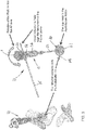
Fig. 3 is a perspective view of the pelvic digitizer device relative to a pelvis in accordance with a method of the present disclosure; -
Fig. 4 is a radiographic image of a pelvis showing an angle between acetabulum line and medio-lateral axis; and -
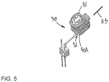
Fig. 5 is a perspective view of a tracker device with inertial sensor unit as used with the pelvic digitizer device ofFig. 1 . - Referring to the drawings and more particularly to
Fig. 1 , there is a pelvic digitizer device in accordance with the present disclosure at 10. Thedevice 10 is of the type used with an inertial sensor unit 11 mounted on atool body 12. The inertial sensor unit 11 may be known as a sourceless sensor, a micro-electromechanical sensor unit (MEMS unit), and has any appropriate set of inertial sensors (e.g., accelerometers, gyroscope) to produce tracking data in at least three degrees of rotation (i.e., the orientation about a set of three axes is tracked) . The sensor unit 11 may be self enclosed in a pod that is connectable in an accurate and predetermined manner to thetool body 12 of thedevice 10. - The
tool body 12 has atool end 20 in the shape of acup 21. Thecup 21 is shaped to match the shape of an acetabulum (e.g., a hemisphere or quasi-hemisphere), and the size of thecup 21 may be selected as a function of pre-operative imaging of the acetabulum, as will be described hereinafter. For this purpose, thecup 21 may be releasably connected to ashaft 22 of thetool body 12, such that acup 21 of appropriate dimension may be selected. Astopper 23 is integral with thecup 21, and may have different configurations as is shown inFig. 2 , including a pointy edge. Moreover, thestopper 23 may rotate relative to theshaft 22, to be turned to a desired orientation to contact bone landmarks. - A
handle 24 is located at an opposite end of thecup 21 on theshaft 22. Thehandle 24 is ergonomically configured to be handled by a user. Avisual guide 25 is a rod that projects transversally from thehandle 24. Thevisual guide 25 is used to visually guide the user in aligning thedevice 10 with the body of the patient. In an alternative embodiment, thevisual guide 25 is a laser or LED light source that emits a visual line for guidance. - A
receptacle 26 is located at the end of thehandle 24, and is configured to receive the sensor unit 11 in the accurate and predetermined manner. Alternatively, the sensor unit 11 may be built-in to thetool body 12. However, in both cases, an orientation of the sensor unit 11 is preset relative to thetool body 12, such that tracking about at least one axis (one rotational degree of freedom) is known when the sensor unit 11 is initialized. According to an embodiment, theshaft 22 and thevisual guide 25 lie in a plane of thedevice 10, and the preset orientation of the sensor unit 11 has its axis normal to the plane of thedevice 10. In other words, when the sensor unit 11 is initialized, for instance by pressing on thebutton 27, an axis of the sensor unit 11 will be normal to the plane of thedevice 10 in which theshaft 22 and the visual guide 25 (or light line produced thereby) lie. - Although not shown, the sensor unit 11 may be equipped with visual interfaces to provide data to a user (e.g., LEDs of different colors, such as green and red), or may be connected to a computer-assisted surgery system to transmit the orientation data thereto. The transmission of data may be wireless, in any appropriate protocol (e.g., Bluetooth, ZigBee, etc).
- Now that the
device 10 has been described, a method of using thedevice 10 to create a pelvic frame of reference (a.k.a., pelvic coordinate system) is set forth. - According to a pre-operative step, the frontal plane of the pelvis of the patient is imaged using any appropriate type of imaging (e.g., X-ray), to obtain an image as in
Fig. 4 . From this image, angle α may be obtained (shown as 40 degrees), as the acetabulum line, i.e., the line crossing portions of the rim of the acetabulum, relative to the medio-lateral axis (hereinafter ML axis). The ML axis may be the line that connects 2 antero-superior iliac spine (ASIS) points or connects the bottom of two teardrops of the pelvis, as shown inFig. 4 . Also, from the image, the cup size that fits the patient's native acetabulum may be evaluated. - The next steps are performed intra-operatively, with the
device 10 being equipped with a sensor unit 11 with preset orientation and thecup 21 dimensioned to match the pre-operative evaluated size. Referring toFig. 3 , with the patient in a strict lateral decubitus (e.g., with the frontal plane being aligned with gravity) with the frontal plane being perpendicular to the substantially horizontal surface of the operating table, for instance as eyeballed using pelvic landmarks, and with the femur being dislocated from the acetabulum, thecup 21 of thedevice 10 is inserted in the native acetabulum before it is reamed. Thestopper 23 is abutted against the rim of the acetabulum to ensure that thecup 21 is properly inserted in the acetabulum. For example, thedevice 10 may be waggled back-and-forth in the patient's acetabulum, while keeping the instrument moving in the patient frontal plane. The waggle motion will be stopped by thestopper 23 on themodular cup 21. In the embodiment of thedevice 10, the stopper 23 points towards the patient's head, but may be configured and rotated to point toward the patient's feet, etc, as a matter of preference of the surgeon, considering the environing soft tissue. Thestopper 23 can be adjustable as to where it is located, so that it adapts to the user's preferences. However, there are few bone landmarks, e.g. acetabulum notch, and it is preferred that thestopper 23 cooperates with these landmarks, whereby the orientation of thestopper 23 may be adjusted relative to theshaft 22 to align thestopper 23 with the bone landmarks. - When the
stopper 23 contacts the rim of the acetabulum, thevisual guide 25 may be visually aligned with the patient's frontal plane. For example, the visual guide 25 (whether a rod or a linear light beam) is pointed towards the patient's head and parallel to the longitudinal axis of the patient. This direction may be arranged to be parallel to the long side of the operating table. Thevisual guide 25 gives a visual indication to keep thedevice 10 moving in a plane that is parallel to the patient's frontal plane. - With the
visual guide 25 held in such a way that it is generally parallel to the frontal plane of the patient, the sensor unit 11 may be turned on. In the illustrated embodiment, the "on"button 27 is conveniently located on thehandle 24. The sensor unit 11 is preset with an orientation, in such a way that orientation about a first rotational degree of freedom is known when the sensor unit 11 is initialized. More specifically, when the sensor unit 11 is turned on, an axis of the sensor unit 11 is normal to the plane of thedevice 10. As the plane of thedevice 10 is parallel to the frontal plane of the patient as a result of the steps set forth above on patient positioning and maneuvering of thedevice 10, the sensor unit 11 has a preset axis aligned with the anterior-posterior (AP) axis of the patient. - The ML axis is then set. As the
stopper 23 is stuck on the rim of the acetabulum and thedevice 10 is maintained parallel to the patient frontal plane, the rim of themodular cup 21 is aligned with the acetabulum line (Fig. 4 ), the shaft of the acetabulum is perpendicular to rim of the modular cup. At this time, the inertial sensor unit 11 will be able to compute the ML axis based on the preoperatively obtained α angle and the known geometrical relation between the inertial sensor unit 11 and thetool body 12 from the preset instrumental parameters. The computation may be done by rotating theshaft 22 of thedevice 10, which is known to theinertial sensor unit 12, by 90-alpha degrees. A command must be given to the sensor unit 11 that the ML axis will be set. These rotations will allow the sensor unit 11 to set the ML axis. - Finally, the cranial-caudal (CC) axis is the cross-product of the AP axis and the ML axis. With the three axes set in the manner described above, the
device 10 is calibrated as a frame of reference about three rotational axes is created between thedevice 10 and the pelvis. - As alterations will be made to the acetabulum, the coordinate system must be transferred from the sensor unit 11 on the
device 10 to a sensor unit of atracking device 30, as shown inFig. 5 . Thetracking device 30 is secured to the pelvis for instance in the receptacle 30A shown, and has asensor unit 31 of similar nature and configuration as the sensor unit 11 of thedevice 10. Theinertial sensor unit 31 has a preset orientation for instance with an axis being aligned with a surface of the receptacle 30A, such that the axis is parallel to gravity when the surface of the receptacle 30A is horizontal. According to an embodiment, thetracking device 30 is pinned to the iliac crest. Thetracking device 30 is then aligned with the horizon, using the readings from thesensor unit 31. Thesensor unit 31 is the equivalent of "bubble" levels being orthogonal to each other. In an embodiment, thesensor unit 31 is connected to a body of thetracking device 30 by a ball joint 32 (or like three rotational DOF joint), to allow such horizontal leveling (and hence for an axis to be parallel to gravity). The various DOFs of the joint 32 may be locked. - With it being level, the
sensor unit 31 is rotated around its normal axis to align avisual guide 33 thereof, such as a rod, with the patient's frontal plane, with these rotations being recorded by thesensor unit 31. Accordingly, thetracking device 30 is aligned with the frontal plane, whereby the AP axis is now common to both thedevices tracking device 30, the pelvic coordinate system may be transferred from the sensor unit 11 of thedevice 10 to thesensor unit 31 of thetracking device 30. The transfer is performed using the common vectors measured by bothsensor units 11 and 31, respectively of thedevice 10 and thedevice 30, to build an equation. The common vectors are the AP-axis and gravity. The equation is solved, and the relation between the trackingdevice 30 and the patient coordinate system of the sensor unit 11 can be found, to complete the pelvis registration. - According to another embodiment, the operating table is rotatable about its transverse axis, i.e., about an axis that is generally normal to the frontal plane of the patient in the strict lateral decubitus. The rotation of the table is used to transfer the pelvic coordinate system from the
device 10 to thetracking device 30. To perform such transfer, thedevice 10 is removed from engagement in the patient's acetabulum. The table is rotated while ensuring that the patient remains generally immovable relative to the table surface. In an embodiment, the OR table is rotated about θ°, remains stable for 15 secs, and then rotated back. While rotating the table, with thetracking device 30 secured to the pelvis of the patient, the readings of thesensor unit 31 are recorded. A tracking device on a table locator, detects the rotation angle (θ) and the rotation axis (r-axis). The expected readings of thedevice 10 can be mathematically calculated: rotation of tracking device x, y, z axes of thedevice 10 respectively {around r-axis, with θ°} as if thedevice 10 was mechanically attached to the pelvis and followed the rotation of the OR table. The patient coordinate system may be transferred from thedevice 10 to thetracking device 30. The readings of bothsensor units 11 and 31 in a first position and second position are used, with the first position being after the calibration of thedevice 10, and the second position being with the OR table inclined by θ° (using in this case the expected reading for the device 10). - Once the frame of reference of the pelvis is transferred to the
pelvic tracking device 30, the pelvis may be tracked in orientation about three rotational degrees of freedom, and this tracking may be used and transferred to tools for instance to determine the anteversion and abduction/adduction angles of these tools. The tools may include reamers, impactors, etc. - The proposed method using the
device 10 requires only the patient frontal plane to be aligned with gravity (i.e. the roll angle of the pelvis is required to be zero; however, tilt angle can be arbitrary). Moreover, the proposed method uses only one radiograph, i.e. the frontal plane X-ray. Moreover, the proposed method is a calibration of thedevices
Claims (11)
- A pelvic digitizer device (10) comprising:
a body (12) comprising:a shaft (22) having a tooling end and a handle end with a handle (24) for being manipulated,a visual guide (25) oriented in a reference plane of the digitizer device, anda cup (21) connected to the tooling end and adapted to be received in an acetabulum of a patient; andan inertial sensor unit (11) connected to the body, the inertial sensor unit having a preset orientation for calibration of the pelvic digitizer device relative to a pelvis of a patient, the preset orientation being based on pre-operative imaging specific to the pelvis of the patient, the preset orientation being aligned with the reference plane,wherein the preset orientation of the inertial sensor unit (11) comprises a preoperatively determined angle of an acetabulum line in a pre-operative image of a pelvis specific to the patient. - The pelvic digitizer device (10) according to claim 1, wherein the visual guide (25) is a light source adapted to produce a line in the reference plane.
- The pelvic digitizer device (10) according to claim 2, wherein the line and the shaft lie in the reference plane.
- The pelvic digitizer device (10) according to claim 1, wherein the visual guide (25) is a rod connected to the handle (24).
- The pelvic digitizer device (10) according to claim 4, wherein the rod is generally transverse to the shaft (22), and the rod and shaft lie in the reference plane.
- The pelvic digitizer device (10) according to any one of claims 1 to 5, further comprising a receptacle (26) in the body (12) for releasably receiving the inertial sensor unit (11) in such a way that the preset orientation of the inertial sensor unit is aligned with the reference plane.
- The pelvic digitizer device (10) according to any one of claims 1 to 6, wherein the preoperatively determined angle of the acetabulum line is angle between the acetabulum line and a medio-lateral axis obtained from a pre-operative image of the patient.
- The pelvic digitizer device (10) according to any one of claims 1 to 7, further comprising a stopper (23) adjacent to a rim of the cup, the stopper being adapted to contact a landmark of an acetabular rim.
- The pelvic digitizer device (10) according to any one of claims 1 to 8, wherein the preset orientation of the inertial sensor unit (11) has an axis normal to the reference plane.
- An assembly of a pelvic digitizer device (11) and pelvic tracker device (30) comprising:the pelvic digitizer device according to any one of claims 1-9; anda pelvic tracker device comprising:a tracker body adapted to be fixed to a pelvis of the patient,another inertial sensor unit (31) with a preset orientation for calibration of the pelvic tracker device, the preset orientation being based on the pre-operative imaging specific to the pelvis of the patient,a three DOF rotational joint (32) between the inertial sensor unit and the body, anda visual guide (33) displaceable with the inertial sensor unit for alignment with the reference plane of the pelvic digitizer device.
- The assembly according to claim 10, further comprising a receptacle (30A) in the tracker body for releasably receiving the inertial sensor unit (31) in such a way that the preset orientation of the inertial sensor unit of the pelvic tracker body is aligned with a plane of the receptacle.
Applications Claiming Priority (2)
| Application Number | Priority Date | Filing Date | Title |
|---|---|---|---|
| US201261677104P | 2012-07-30 | 2012-07-30 | |
| PCT/CA2013/050589 WO2014019086A1 (en) | 2012-07-30 | 2013-07-30 | Pelvic digitizer device with inertial sensor unit and method |
Publications (3)
| Publication Number | Publication Date |
|---|---|
| EP2879610A1 EP2879610A1 (en) | 2015-06-10 |
| EP2879610A4 EP2879610A4 (en) | 2016-04-13 |
| EP2879610B1 true EP2879610B1 (en) | 2020-03-04 |
Family
ID=49995530
Family Applications (1)
| Application Number | Title | Priority Date | Filing Date |
|---|---|---|---|
| EP13825223.4A Active EP2879610B1 (en) | 2012-07-30 | 2013-07-30 | Pelvic digitizer device with inertial sensor unit and method |
Country Status (5)
| Country | Link |
|---|---|
| US (1) | US10092218B2 (en) |
| EP (1) | EP2879610B1 (en) |
| CN (1) | CN104220021B (en) |
| CA (1) | CA2866192C (en) |
| WO (1) | WO2014019086A1 (en) |
Families Citing this family (20)
| Publication number | Priority date | Publication date | Assignee | Title |
|---|---|---|---|---|
| US9539112B2 (en) * | 2012-03-28 | 2017-01-10 | Robert L. Thornberry | Computer-guided system for orienting a prosthetic acetabular cup in the acetabulum during total hip replacement surgery |
| US9700433B2 (en) * | 2012-11-28 | 2017-07-11 | Tecomet, Inc | Patient-specific acetabular alignment guide and method |
| US9247998B2 (en) | 2013-03-15 | 2016-02-02 | Intellijoint Surgical Inc. | System and method for intra-operative leg position measurement |
| US20140276889A1 (en) * | 2013-03-15 | 2014-09-18 | William C. Head | Portable surgical guide with laser, abduction and anteversion measuring system and method of using same |
| US20140303631A1 (en) * | 2013-04-05 | 2014-10-09 | Thornberry Technologies, LLC | Method and apparatus for determining the orientation and/or position of an object during a medical procedure |
| EP3137019B1 (en) * | 2014-04-30 | 2019-03-20 | Zimmer, Inc. | Acetabular cup impacting using patient-specific instrumentation |
| WO2016123700A1 (en) * | 2015-02-02 | 2016-08-11 | Orthosoft Inc. | Mechanically guided impactor for hip arthroplasty |
| EP3253322B1 (en) * | 2015-02-02 | 2020-03-11 | Orthosoft ULC | Acetabulum rim digitizer device |
| WO2016123702A1 (en) * | 2015-02-02 | 2016-08-11 | Orthosoft Inc. | A method and device for cup implanting using inertial sensors |
| GB201621373D0 (en) * | 2016-12-15 | 2017-02-01 | Depuy Ireland Ultd Co | Pelvic referencing guide |
| EP3595554A4 (en) * | 2017-03-14 | 2021-01-06 | OrthAlign, Inc. | Hip replacement navigation systems and methods |
| US11065069B2 (en) | 2017-05-10 | 2021-07-20 | Mako Surgical Corp. | Robotic spine surgery system and methods |
| US11033341B2 (en) | 2017-05-10 | 2021-06-15 | Mako Surgical Corp. | Robotic spine surgery system and methods |
| AU2019212626B2 (en) | 2018-01-26 | 2024-10-10 | Mako Surgical Corp. | End effectors, systems, and methods for impacting prosthetics guided by surgical robots |
| US10779893B2 (en) * | 2018-10-18 | 2020-09-22 | Warsaw Orthopedic, Inc. | Spinal implant system and method |
| JP7407442B2 (en) * | 2019-01-15 | 2024-01-04 | インテリジョイント サージカル インク. | Systems, devices, and computer-implemented methods for bone reorientation |
| CN109846528B (en) * | 2019-03-01 | 2021-04-02 | 山东新华联合骨科器材股份有限公司 | Joint replacement surgery auxiliary positioning method and system based on inertial navigation |
| KR20220159392A (en) | 2020-03-27 | 2022-12-02 | 마코 서지컬 코포레이션 | Robotic spine surgery system and method using haptic interface |
| CN114848242B (en) * | 2022-04-24 | 2026-04-10 | 北京医迈科技有限公司 | Angle measuring and positioning device for hip replacement surgery |
| US12588957B2 (en) | 2022-06-03 | 2026-03-31 | Mako Surgical Corp. | Surgical robotic system with compliance mechanism |
Family Cites Families (19)
| Publication number | Priority date | Publication date | Assignee | Title |
|---|---|---|---|---|
| NO20011769D0 (en) * | 2001-04-06 | 2001-04-06 | Bjoern Franc Iversen | Device and system for mutual positioning of prosthetic parts |
| DE10306793A1 (en) | 2002-05-21 | 2003-12-04 | Plus Endoprothetik Ag Rotkreuz | Arrangement and method for the intraoperative determination of the position of a joint replacement implant |
| ATE452591T1 (en) | 2002-10-04 | 2010-01-15 | Orthosoft Inc | DEVICE FOR OBTAINING AN AXIS OF AN INTRAMEDULAR CANAL |
| US7559931B2 (en) * | 2003-06-09 | 2009-07-14 | OrthAlign, Inc. | Surgical orientation system and method |
| US8175683B2 (en) * | 2003-12-30 | 2012-05-08 | Depuy Products, Inc. | System and method of designing and manufacturing customized instrumentation for accurate implantation of prosthesis by utilizing computed tomography data |
| US8568487B2 (en) * | 2006-02-27 | 2013-10-29 | Biomet Manufacturing, Llc | Patient-specific hip joint devices |
| US7594933B2 (en) | 2006-08-08 | 2009-09-29 | Aesculap Ag | Method and apparatus for positioning a bone prosthesis using a localization system |
| US9161844B2 (en) * | 2007-04-03 | 2015-10-20 | Finsbury (Development) Limited | Method of using a trial acetabular cup for insertion of an acetabular prosthesis |
| GB2448740B (en) | 2007-04-26 | 2012-03-14 | Derek James Wallace Mcminn | Alignment device |
| DE102008053566A1 (en) * | 2007-11-27 | 2009-06-04 | Bernhard Hildebrandt | System of endoprostheses and devices for the minimally invasive and cementless implantation of endoprostheses of the shoulder and the hip and the offset improvement of the femoral neck |
| WO2010030809A1 (en) * | 2008-09-10 | 2010-03-18 | Orthalign, Inc | Hip surgery systems and methods |
| US8588892B2 (en) * | 2008-12-02 | 2013-11-19 | Avenir Medical Inc. | Method and system for aligning a prosthesis during surgery using active sensors |
| US20110060339A1 (en) * | 2009-09-09 | 2011-03-10 | De Wekker Erwin | Hip surgery assembly |
| US8709016B2 (en) * | 2009-12-11 | 2014-04-29 | Curexo Technology Corporation | Surgical guide system using an active robot arm |
| US9901405B2 (en) * | 2010-03-02 | 2018-02-27 | Orthosoft Inc. | MEMS-based method and system for tracking a femoral frame of reference |
| CA2809694C (en) * | 2010-08-31 | 2017-05-30 | Orthosoft Ulc | Tool and method for digital acquisition of a tibial mechanical axis |
| WO2012080840A1 (en) * | 2010-12-17 | 2012-06-21 | Avenir Medical Inc. | Method and system for aligning a prosthesis during surgery |
| US9554731B2 (en) * | 2011-02-08 | 2017-01-31 | The General Hospital Corporation | Patient positioning systems and methods |
| WO2012171577A1 (en) * | 2011-06-17 | 2012-12-20 | Brainlab Ag | Method, system and device for positioning an implant |
-
2013
- 2013-07-30 US US13/954,288 patent/US10092218B2/en active Active
- 2013-07-30 WO PCT/CA2013/050589 patent/WO2014019086A1/en not_active Ceased
- 2013-07-30 EP EP13825223.4A patent/EP2879610B1/en active Active
- 2013-07-30 CA CA2866192A patent/CA2866192C/en active Active
- 2013-07-30 CN CN201380019916.5A patent/CN104220021B/en not_active Expired - Fee Related
Non-Patent Citations (1)
| Title |
|---|
| None * |
Also Published As
| Publication number | Publication date |
|---|---|
| US20140031722A1 (en) | 2014-01-30 |
| CN104220021A (en) | 2014-12-17 |
| EP2879610A4 (en) | 2016-04-13 |
| US10092218B2 (en) | 2018-10-09 |
| CA2866192C (en) | 2021-02-23 |
| WO2014019086A1 (en) | 2014-02-06 |
| EP2879610A1 (en) | 2015-06-10 |
| CN104220021B (en) | 2019-02-19 |
| CA2866192A1 (en) | 2014-02-06 |
Similar Documents
| Publication | Publication Date | Title |
|---|---|---|
| US10092218B2 (en) | Pelvic digitizer device with inertial sensor unit and method | |
| US11090170B2 (en) | Acetabular cup prosthesis positioning instrument and method | |
| US11517382B2 (en) | Method and device for cup implanting using inertial sensors | |
| US10405928B2 (en) | Acetabulum rim digitizer device and method | |
| US20210259854A1 (en) | Instrument navigation in computer-assisted hip surgery | |
| US20190282321A1 (en) | Acetabular cup impacting using patient-specific instrumentation | |
| JP2022553783A (en) | Systems and methods for computer-assisted surgical navigation to perform 3D scanning | |
| US20170119475A1 (en) | Systems, methods and devices for calculating hip center of rotation, adjusting parameters of joint replacement for pelvic tilt and calculating leg length and offset | |
| EP3595554A1 (en) | Hip replacement navigation systems and methods | |
| CA2974837C (en) | Acetabulum rim digitizer device and method | |
| CA2974848C (en) | A method and device for cup implanting using inertial sensors | |
| WO2013110910A1 (en) | Alignment guide with spirit level |
Legal Events
| Date | Code | Title | Description |
|---|---|---|---|
| PUAI | Public reference made under article 153(3) epc to a published international application that has entered the european phase |
Free format text: ORIGINAL CODE: 0009012 |
|
| 17P | Request for examination filed |
Effective date: 20150302 |
|
| AK | Designated contracting states |
Kind code of ref document: A1 Designated state(s): AL AT BE BG CH CY CZ DE DK EE ES FI FR GB GR HR HU IE IS IT LI LT LU LV MC MK MT NL NO PL PT RO RS SE SI SK SM TR |
|
| AX | Request for extension of the european patent |
Extension state: BA ME |
|
| DAX | Request for extension of the european patent (deleted) | ||
| REG | Reference to a national code |
Ref country code: DE Ref legal event code: R079 Ref document number: 602013066517 Country of ref document: DE Free format text: PREVIOUS MAIN CLASS: A61B0019000000 Ipc: A61B0034200000 |
|
| RA4 | Supplementary search report drawn up and despatched (corrected) |
Effective date: 20160314 |
|
| RIC1 | Information provided on ipc code assigned before grant |
Ipc: A61F 2/32 20060101ALI20160308BHEP Ipc: A61B 34/20 20160101AFI20160308BHEP Ipc: A61B 17/56 20060101ALI20160308BHEP Ipc: A61F 2/46 20060101ALI20160308BHEP |
|
| STAA | Information on the status of an ep patent application or granted ep patent |
Free format text: STATUS: EXAMINATION IS IN PROGRESS |
|
| 17Q | First examination report despatched |
Effective date: 20170327 |
|
| GRAP | Despatch of communication of intention to grant a patent |
Free format text: ORIGINAL CODE: EPIDOSNIGR1 |
|
| STAA | Information on the status of an ep patent application or granted ep patent |
Free format text: STATUS: GRANT OF PATENT IS INTENDED |
|
| INTG | Intention to grant announced |
Effective date: 20190913 |
|
| RAP1 | Party data changed (applicant data changed or rights of an application transferred) |
Owner name: ORTHOSOFT ULC |
|
| GRAS | Grant fee paid |
Free format text: ORIGINAL CODE: EPIDOSNIGR3 |
|
| GRAA | (expected) grant |
Free format text: ORIGINAL CODE: 0009210 |
|
| STAA | Information on the status of an ep patent application or granted ep patent |
Free format text: STATUS: THE PATENT HAS BEEN GRANTED |
|
| AK | Designated contracting states |
Kind code of ref document: B1 Designated state(s): AL AT BE BG CH CY CZ DE DK EE ES FI FR GB GR HR HU IE IS IT LI LT LU LV MC MK MT NL NO PL PT RO RS SE SI SK SM TR |
|
| REG | Reference to a national code |
Ref country code: GB Ref legal event code: FG4D |
|
| REG | Reference to a national code |
Ref country code: CH Ref legal event code: EP Ref country code: CH Ref legal event code: NV Representative=s name: MICHELI AND CIE SA, CH |
|
| REG | Reference to a national code |
Ref country code: AT Ref legal event code: REF Ref document number: 1239504 Country of ref document: AT Kind code of ref document: T Effective date: 20200315 |
|
| REG | Reference to a national code |
Ref country code: DE Ref legal event code: R096 Ref document number: 602013066517 Country of ref document: DE |
|
| REG | Reference to a national code |
Ref country code: IE Ref legal event code: FG4D |
|
| PG25 | Lapsed in a contracting state [announced via postgrant information from national office to epo] |
Ref country code: NO Free format text: LAPSE BECAUSE OF FAILURE TO SUBMIT A TRANSLATION OF THE DESCRIPTION OR TO PAY THE FEE WITHIN THE PRESCRIBED TIME-LIMIT Effective date: 20200604 Ref country code: RS Free format text: LAPSE BECAUSE OF FAILURE TO SUBMIT A TRANSLATION OF THE DESCRIPTION OR TO PAY THE FEE WITHIN THE PRESCRIBED TIME-LIMIT Effective date: 20200304 Ref country code: FI Free format text: LAPSE BECAUSE OF FAILURE TO SUBMIT A TRANSLATION OF THE DESCRIPTION OR TO PAY THE FEE WITHIN THE PRESCRIBED TIME-LIMIT Effective date: 20200304 |
|
| PGFP | Annual fee paid to national office [announced via postgrant information from national office to epo] |
Ref country code: CH Payment date: 20200617 Year of fee payment: 8 |
|
| REG | Reference to a national code |
Ref country code: NL Ref legal event code: MP Effective date: 20200304 |
|
| PG25 | Lapsed in a contracting state [announced via postgrant information from national office to epo] |
Ref country code: LV Free format text: LAPSE BECAUSE OF FAILURE TO SUBMIT A TRANSLATION OF THE DESCRIPTION OR TO PAY THE FEE WITHIN THE PRESCRIBED TIME-LIMIT Effective date: 20200304 Ref country code: SE Free format text: LAPSE BECAUSE OF FAILURE TO SUBMIT A TRANSLATION OF THE DESCRIPTION OR TO PAY THE FEE WITHIN THE PRESCRIBED TIME-LIMIT Effective date: 20200304 Ref country code: GR Free format text: LAPSE BECAUSE OF FAILURE TO SUBMIT A TRANSLATION OF THE DESCRIPTION OR TO PAY THE FEE WITHIN THE PRESCRIBED TIME-LIMIT Effective date: 20200605 Ref country code: HR Free format text: LAPSE BECAUSE OF FAILURE TO SUBMIT A TRANSLATION OF THE DESCRIPTION OR TO PAY THE FEE WITHIN THE PRESCRIBED TIME-LIMIT Effective date: 20200304 Ref country code: BG Free format text: LAPSE BECAUSE OF FAILURE TO SUBMIT A TRANSLATION OF THE DESCRIPTION OR TO PAY THE FEE WITHIN THE PRESCRIBED TIME-LIMIT Effective date: 20200604 |
|
| REG | Reference to a national code |
Ref country code: LT Ref legal event code: MG4D |
|
| PG25 | Lapsed in a contracting state [announced via postgrant information from national office to epo] |
Ref country code: NL Free format text: LAPSE BECAUSE OF FAILURE TO SUBMIT A TRANSLATION OF THE DESCRIPTION OR TO PAY THE FEE WITHIN THE PRESCRIBED TIME-LIMIT Effective date: 20200304 |
|
| REG | Reference to a national code |
Ref country code: DE Ref legal event code: R082 Ref document number: 602013066517 Country of ref document: DE Representative=s name: VENNER SHIPLEY GERMANY LLP, DE Ref country code: DE Ref legal event code: R082 Ref document number: 602013066517 Country of ref document: DE Representative=s name: VENNER SHIPLEY LLP, DE |
|
| PG25 | Lapsed in a contracting state [announced via postgrant information from national office to epo] |
Ref country code: EE Free format text: LAPSE BECAUSE OF FAILURE TO SUBMIT A TRANSLATION OF THE DESCRIPTION OR TO PAY THE FEE WITHIN THE PRESCRIBED TIME-LIMIT Effective date: 20200304 Ref country code: ES Free format text: LAPSE BECAUSE OF FAILURE TO SUBMIT A TRANSLATION OF THE DESCRIPTION OR TO PAY THE FEE WITHIN THE PRESCRIBED TIME-LIMIT Effective date: 20200304 Ref country code: LT Free format text: LAPSE BECAUSE OF FAILURE TO SUBMIT A TRANSLATION OF THE DESCRIPTION OR TO PAY THE FEE WITHIN THE PRESCRIBED TIME-LIMIT Effective date: 20200304 Ref country code: CZ Free format text: LAPSE BECAUSE OF FAILURE TO SUBMIT A TRANSLATION OF THE DESCRIPTION OR TO PAY THE FEE WITHIN THE PRESCRIBED TIME-LIMIT Effective date: 20200304 Ref country code: RO Free format text: LAPSE BECAUSE OF FAILURE TO SUBMIT A TRANSLATION OF THE DESCRIPTION OR TO PAY THE FEE WITHIN THE PRESCRIBED TIME-LIMIT Effective date: 20200304 Ref country code: IS Free format text: LAPSE BECAUSE OF FAILURE TO SUBMIT A TRANSLATION OF THE DESCRIPTION OR TO PAY THE FEE WITHIN THE PRESCRIBED TIME-LIMIT Effective date: 20200704 Ref country code: SK Free format text: LAPSE BECAUSE OF FAILURE TO SUBMIT A TRANSLATION OF THE DESCRIPTION OR TO PAY THE FEE WITHIN THE PRESCRIBED TIME-LIMIT Effective date: 20200304 Ref country code: PT Free format text: LAPSE BECAUSE OF FAILURE TO SUBMIT A TRANSLATION OF THE DESCRIPTION OR TO PAY THE FEE WITHIN THE PRESCRIBED TIME-LIMIT Effective date: 20200729 Ref country code: SM Free format text: LAPSE BECAUSE OF FAILURE TO SUBMIT A TRANSLATION OF THE DESCRIPTION OR TO PAY THE FEE WITHIN THE PRESCRIBED TIME-LIMIT Effective date: 20200304 |
|
| REG | Reference to a national code |
Ref country code: AT Ref legal event code: MK05 Ref document number: 1239504 Country of ref document: AT Kind code of ref document: T Effective date: 20200304 |
|
| REG | Reference to a national code |
Ref country code: DE Ref legal event code: R097 Ref document number: 602013066517 Country of ref document: DE |
|
| PLBE | No opposition filed within time limit |
Free format text: ORIGINAL CODE: 0009261 |
|
| STAA | Information on the status of an ep patent application or granted ep patent |
Free format text: STATUS: NO OPPOSITION FILED WITHIN TIME LIMIT |
|
| PG25 | Lapsed in a contracting state [announced via postgrant information from national office to epo] |
Ref country code: AT Free format text: LAPSE BECAUSE OF FAILURE TO SUBMIT A TRANSLATION OF THE DESCRIPTION OR TO PAY THE FEE WITHIN THE PRESCRIBED TIME-LIMIT Effective date: 20200304 Ref country code: IT Free format text: LAPSE BECAUSE OF FAILURE TO SUBMIT A TRANSLATION OF THE DESCRIPTION OR TO PAY THE FEE WITHIN THE PRESCRIBED TIME-LIMIT Effective date: 20200304 Ref country code: DK Free format text: LAPSE BECAUSE OF FAILURE TO SUBMIT A TRANSLATION OF THE DESCRIPTION OR TO PAY THE FEE WITHIN THE PRESCRIBED TIME-LIMIT Effective date: 20200304 |
|
| 26N | No opposition filed |
Effective date: 20201207 |
|
| PG25 | Lapsed in a contracting state [announced via postgrant information from national office to epo] |
Ref country code: SI Free format text: LAPSE BECAUSE OF FAILURE TO SUBMIT A TRANSLATION OF THE DESCRIPTION OR TO PAY THE FEE WITHIN THE PRESCRIBED TIME-LIMIT Effective date: 20200304 Ref country code: MC Free format text: LAPSE BECAUSE OF FAILURE TO SUBMIT A TRANSLATION OF THE DESCRIPTION OR TO PAY THE FEE WITHIN THE PRESCRIBED TIME-LIMIT Effective date: 20200304 Ref country code: PL Free format text: LAPSE BECAUSE OF FAILURE TO SUBMIT A TRANSLATION OF THE DESCRIPTION OR TO PAY THE FEE WITHIN THE PRESCRIBED TIME-LIMIT Effective date: 20200304 |
|
| REG | Reference to a national code |
Ref country code: BE Ref legal event code: MM Effective date: 20200731 |
|
| PG25 | Lapsed in a contracting state [announced via postgrant information from national office to epo] |
Ref country code: LU Free format text: LAPSE BECAUSE OF NON-PAYMENT OF DUE FEES Effective date: 20200730 |
|
| PG25 | Lapsed in a contracting state [announced via postgrant information from national office to epo] |
Ref country code: BE Free format text: LAPSE BECAUSE OF NON-PAYMENT OF DUE FEES Effective date: 20200731 |
|
| PG25 | Lapsed in a contracting state [announced via postgrant information from national office to epo] |
Ref country code: IE Free format text: LAPSE BECAUSE OF NON-PAYMENT OF DUE FEES Effective date: 20200730 |
|
| REG | Reference to a national code |
Ref country code: CH Ref legal event code: PL |
|
| PG25 | Lapsed in a contracting state [announced via postgrant information from national office to epo] |
Ref country code: LI Free format text: LAPSE BECAUSE OF NON-PAYMENT OF DUE FEES Effective date: 20210731 Ref country code: CH Free format text: LAPSE BECAUSE OF NON-PAYMENT OF DUE FEES Effective date: 20210731 |
|
| PG25 | Lapsed in a contracting state [announced via postgrant information from national office to epo] |
Ref country code: TR Free format text: LAPSE BECAUSE OF FAILURE TO SUBMIT A TRANSLATION OF THE DESCRIPTION OR TO PAY THE FEE WITHIN THE PRESCRIBED TIME-LIMIT Effective date: 20200304 Ref country code: MT Free format text: LAPSE BECAUSE OF FAILURE TO SUBMIT A TRANSLATION OF THE DESCRIPTION OR TO PAY THE FEE WITHIN THE PRESCRIBED TIME-LIMIT Effective date: 20200304 Ref country code: CY Free format text: LAPSE BECAUSE OF FAILURE TO SUBMIT A TRANSLATION OF THE DESCRIPTION OR TO PAY THE FEE WITHIN THE PRESCRIBED TIME-LIMIT Effective date: 20200304 |
|
| PG25 | Lapsed in a contracting state [announced via postgrant information from national office to epo] |
Ref country code: MK Free format text: LAPSE BECAUSE OF FAILURE TO SUBMIT A TRANSLATION OF THE DESCRIPTION OR TO PAY THE FEE WITHIN THE PRESCRIBED TIME-LIMIT Effective date: 20200304 Ref country code: AL Free format text: LAPSE BECAUSE OF FAILURE TO SUBMIT A TRANSLATION OF THE DESCRIPTION OR TO PAY THE FEE WITHIN THE PRESCRIBED TIME-LIMIT Effective date: 20200304 |
|
| P01 | Opt-out of the competence of the unified patent court (upc) registered |
Effective date: 20230526 |
|
| PGFP | Annual fee paid to national office [announced via postgrant information from national office to epo] |
Ref country code: GB Payment date: 20250604 Year of fee payment: 13 |
|
| PGFP | Annual fee paid to national office [announced via postgrant information from national office to epo] |
Ref country code: FR Payment date: 20250603 Year of fee payment: 13 |
|
| PGFP | Annual fee paid to national office [announced via postgrant information from national office to epo] |
Ref country code: DE Payment date: 20250603 Year of fee payment: 13 |