EP2879404A1 - Back cavity microphone implementation - Google Patents
Back cavity microphone implementation Download PDFInfo
- Publication number
- EP2879404A1 EP2879404A1 EP14195411.5A EP14195411A EP2879404A1 EP 2879404 A1 EP2879404 A1 EP 2879404A1 EP 14195411 A EP14195411 A EP 14195411A EP 2879404 A1 EP2879404 A1 EP 2879404A1
- Authority
- EP
- European Patent Office
- Prior art keywords
- back cavity
- loudspeaker
- microphone
- port
- representation
- Prior art date
- Legal status (The legal status is an assumption and is not a legal conclusion. Google has not performed a legal analysis and makes no representation as to the accuracy of the status listed.)
- Ceased
Links
Images




Classifications
-
- H—ELECTRICITY
- H04—ELECTRIC COMMUNICATION TECHNIQUE
- H04R—LOUDSPEAKERS, MICROPHONES, GRAMOPHONE PICK-UPS OR LIKE ACOUSTIC ELECTROMECHANICAL TRANSDUCERS; ELECTRIC HEARING AIDS; PUBLIC ADDRESS SYSTEMS
- H04R1/00—Details of transducers, loudspeakers or microphones
- H04R1/20—Arrangements for obtaining desired frequency or directional characteristics
- H04R1/22—Arrangements for obtaining desired frequency or directional characteristics for obtaining desired frequency characteristic only
- H04R1/28—Transducer mountings or enclosures modified by provision of mechanical or acoustic impedances, e.g. resonator, damping means
- H04R1/2803—Transducer mountings or enclosures modified by provision of mechanical or acoustic impedances, e.g. resonator, damping means for loudspeaker transducers
-
- G—PHYSICS
- G10—MUSICAL INSTRUMENTS; ACOUSTICS
- G10K—SOUND-PRODUCING DEVICES; METHODS OR DEVICES FOR PROTECTING AGAINST, OR FOR DAMPING, NOISE OR OTHER ACOUSTIC WAVES IN GENERAL; ACOUSTICS NOT OTHERWISE PROVIDED FOR
- G10K11/00—Methods or devices for transmitting, conducting or directing sound in general; Methods or devices for protecting against, or for damping, noise or other acoustic waves in general
- G10K11/16—Methods or devices for protecting against, or for damping, noise or other acoustic waves in general
-
- H—ELECTRICITY
- H04—ELECTRIC COMMUNICATION TECHNIQUE
- H04R—LOUDSPEAKERS, MICROPHONES, GRAMOPHONE PICK-UPS OR LIKE ACOUSTIC ELECTROMECHANICAL TRANSDUCERS; ELECTRIC HEARING AIDS; PUBLIC ADDRESS SYSTEMS
- H04R29/00—Monitoring arrangements; Testing arrangements
- H04R29/001—Monitoring arrangements; Testing arrangements for loudspeakers
-
- H—ELECTRICITY
- H04—ELECTRIC COMMUNICATION TECHNIQUE
- H04R—LOUDSPEAKERS, MICROPHONES, GRAMOPHONE PICK-UPS OR LIKE ACOUSTIC ELECTROMECHANICAL TRANSDUCERS; ELECTRIC HEARING AIDS; PUBLIC ADDRESS SYSTEMS
- H04R3/00—Circuits for transducers
- H04R3/02—Circuits for transducers for preventing acoustic reaction, i.e. acoustic oscillatory feedback
-
- H—ELECTRICITY
- H04—ELECTRIC COMMUNICATION TECHNIQUE
- H04R—LOUDSPEAKERS, MICROPHONES, GRAMOPHONE PICK-UPS OR LIKE ACOUSTIC ELECTROMECHANICAL TRANSDUCERS; ELECTRIC HEARING AIDS; PUBLIC ADDRESS SYSTEMS
- H04R1/00—Details of transducers, loudspeakers or microphones
- H04R1/20—Arrangements for obtaining desired frequency or directional characteristics
- H04R1/22—Arrangements for obtaining desired frequency or directional characteristics for obtaining desired frequency characteristic only
- H04R1/28—Transducer mountings or enclosures modified by provision of mechanical or acoustic impedances, e.g. resonator, damping means
- H04R1/2807—Enclosures comprising vibrating or resonating arrangements
- H04R1/2815—Enclosures comprising vibrating or resonating arrangements of the bass reflex type
- H04R1/2823—Vents, i.e. ports, e.g. shape thereof or tuning thereof with damping material
- H04R1/2826—Vents, i.e. ports, e.g. shape thereof or tuning thereof with damping material for loudspeaker transducers
-
- H—ELECTRICITY
- H04—ELECTRIC COMMUNICATION TECHNIQUE
- H04R—LOUDSPEAKERS, MICROPHONES, GRAMOPHONE PICK-UPS OR LIKE ACOUSTIC ELECTROMECHANICAL TRANSDUCERS; ELECTRIC HEARING AIDS; PUBLIC ADDRESS SYSTEMS
- H04R1/00—Details of transducers, loudspeakers or microphones
- H04R1/20—Arrangements for obtaining desired frequency or directional characteristics
- H04R1/22—Arrangements for obtaining desired frequency or directional characteristics for obtaining desired frequency characteristic only
- H04R1/28—Transducer mountings or enclosures modified by provision of mechanical or acoustic impedances, e.g. resonator, damping means
- H04R1/2807—Enclosures comprising vibrating or resonating arrangements
- H04R1/283—Enclosures comprising vibrating or resonating arrangements using a passive diaphragm
- H04R1/2834—Enclosures comprising vibrating or resonating arrangements using a passive diaphragm for loudspeaker transducers
-
- H—ELECTRICITY
- H04—ELECTRIC COMMUNICATION TECHNIQUE
- H04R—LOUDSPEAKERS, MICROPHONES, GRAMOPHONE PICK-UPS OR LIKE ACOUSTIC ELECTROMECHANICAL TRANSDUCERS; ELECTRIC HEARING AIDS; PUBLIC ADDRESS SYSTEMS
- H04R2499/00—Aspects covered by H04R or H04S not otherwise provided for in their subgroups
- H04R2499/10—General applications
- H04R2499/11—Transducers incorporated or for use in hand-held devices, e.g. mobile phones, PDA's, camera's
-
- H—ELECTRICITY
- H04—ELECTRIC COMMUNICATION TECHNIQUE
- H04R—LOUDSPEAKERS, MICROPHONES, GRAMOPHONE PICK-UPS OR LIKE ACOUSTIC ELECTROMECHANICAL TRANSDUCERS; ELECTRIC HEARING AIDS; PUBLIC ADDRESS SYSTEMS
- H04R3/00—Circuits for transducers
- H04R3/002—Damping circuit arrangements for transducers, e.g. motional feedback circuits
Definitions
- Loudspeaker diaphragm motion generates acoustic energy in front of and behind the loudspeaker.
- the acoustic energy in front provides the expected loudspeaker acoustic output.
- the acoustic energy in the back is usually confined so that it does not interfere with the loudspeaker acoustic output in the front, but can provide a measure of the loudspeaker acoustic output.
- loudspeakers are usually implemented with a sealed back cavity design. That is, the acoustic energy generated in the back of the loudspeaker is confined within a sealed cavity.
- an acoustic pressure measurement in the back cavity serves as a measure of the loudspeaker acoustic output.
- the loudspeaker acoustic output serves as a reference for many purposes.
- the loudspeaker acoustic output is used as a reference in digital signal processing (DSP) algorithms such as echo cancellation.
- DSP digital signal processing
- the loudspeaker acoustic output is a measure used for many purposes including, for example, as a reference in echo cancellation.
- the acoustic pressure in a back cavity of the loudspeaker is a measure of the loudspeaker acoustic output in most handheld devices.
- the back cavity pressure measurement may be a more accurate measure for echo cancellation than the traditional voltage applied to the loudspeaker, especially in handheld devices. This is because loudspeakers, used in handheld devices, often display nonlinear distortion that makes the echo path nonlinear. Using the back cavity pressure measurement as the reference signal gives the echo cancellation algorithm a more accurate measure of the true acoustic signal to cancel.
- the microphones used in handheld devices cannot handle the high sound pressure levels (SPL) in the back cavity of the loudspeaker so that obtaining the back cavity pressure is not possible with typical handheld device microphones.
- SPL sound pressure levels
- lumped element analysis provides an SPL simulation that indicates SPLs in the back cavity are on the order of 55 decibel Pascal (dBPa) in handheld devices.
- typical microphones used in smart phones can deal with 15 to 25 dBPa, and even higher performance microphones deal with only 35 to 40 dBPa.
- applications that require loudspeaker acoustic output have used other references for signal processing.
- echo cancellation for example, the voltage applied to the loudspeaker to produce the audio output has been used as a reference.
- the voltage reference does not result in accurate echo cancellation.
- measuring the acoustic pressure in front of the loudspeaker results in an unreliable signal, because acoustic coupling changes based on how a handheld device is held and also because the signal is contaminated with the addition of sound sources (e.g., room noise, handheld device user's voice).
- Embodiments of the system and method described herein relate to obtaining an attenuated measure of the back cavity pressure as a representation of loudspeaker acoustic output.
- FIG. 1 is a block diagram of a physical system for obtaining a representation of loudspeaker acoustic output according to an embodiment of the invention.
- a transparent box is shown as a representation of the device 100 that comprises the system for obtaining the representation of loudspeaker acoustic output.
- the device 100 may be a smart phone, a cell phone, or another handheld device, for example.
- the loudspeaker 110 of the device 100 is shown with a sealed back cavity 120. While the back cavity 120 is shown in the shape of a cube, alternate shapes are contemplated for both the loudspeaker 110 and the back cavity.
- An in port 130 e.g., hole
- a microphone 140 is disposed at the opening or in port 130 in the back cavity 120.
- An optional out port 150 (e.g., tube) is arranged at the microphone 140 and extends to the interior of the device 100.
- the ports (in port 130 and out port 150) may both be holes (in the back cavity 120 and in the microphone 140) or one or both may be a tube or have a non-circular cross section.
- Exemplary dimensions for the in port 130 implemented as a tube may be on the order of 0.3 millimeters (mm) in length with a circular cross section and a diameter on the order of 0.1 mm.
- Exemplary dimensions for the out port 150 implemented as a tube may be on the order of 1 mm for the length and 1 mm for the diameter.
- Figure 2 is an acoustic circuit model of the system shown in Figure 1 .
- the system comprises a filter implementation to attenuate the sound from the back cavity 120 to the microphone 140 so that a standard microphone 140 in a device 100 (e.g., handheld) can pick up the sound.
- the filter implementation includes the in port 130 which may be a hole, for example. As the acoustic circuit model of Figure 2 indicates, the in port 130 leads directly to a microphone 140.
- the out port 150 which may be another hole or a tube from the front of the microphone 140 leads to the interior of the device 100 (e.g., smart phone).
- the microphone 140 acoustic impedance which is largely capacitive, is part of the filter implementation that attenuates the sound from the back cavity 120.
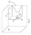
- FIG 3 is a block diagram of another system for obtaining a representation of loudspeaker acoustic output according to another embodiment of the invention.
- the loudspeaker 110 and back cavity 120 are shown in a device 100 illustrated as a transparent box.
- the back cavity 120 may have a different shape than the cube shown in Figure 3 .
- the SPL in the back cavity 120 is attenuated by a diaphragm 350 (e.g., metal disk).
- the diaphragm 350 is formed inside the back cavity 120 at an opening 330 (hole) in the back cavity 120.
- a microphone 140 on the other side of the opening 330 receives an attenuated acoustic pressure based on the diaphragm 350.
- the pressure in the back cavity 120 distends the diaphragm 350. As the thickness of the diaphragm 350 increases, the pressure decreases. Thus, the amount of attenuation of the SPL at the microphone 140 can be controlled by controlling the thickness of the diaphragm 350.
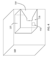
- FIG 4 is a block diagram of another system for obtaining a representation of loudspeaker acoustic output according to another embodiment of the invention.
- the loudspeaker 110 and back cavity 120 are shown in a device 100 illustrated as a transparent box.
- the device 100 and the back cavity 120 may have different shapes than shown in Figure 4 .
- the accelerometer 410 may be mounted to one of the walls 125 of the back cavity 120, as shown in Figure 4 .
- the wall 125 flexes under the load of the SPL in the back cavity 120. This flexing by the wall 125 is sensed by the accelerometer such that the accelerometer output is an attenuated representation of loudspeaker acoustic output.
- the amplitude of the flexing can be adjusted by changing the shape and thickness of the wall 125 (changing the spring constant).
- the wall 125 acts as a diaphragm and the accelerometer 410 may be thought of as a contact microphone indicating the pressure proportional to SPL in the back cavity 120.
- FIG. 5 is a process flow of a method of performing signal processing using loudspeaker 110 output according to embodiments of the invention.
- the arranging may include disposing an in port 130 and out port 150 at a wall of the back cavity 120 with a microphone 140 therebetween, as discussed with reference to Figure 1 and 2 .
- the arranging may also include disposing a diaphragm 350 inside an opening 330 of the back cavity 120 with a microphone 140 on the other side of the opening 330, as discussed with reference to Figure 3 .
- the arranging may instead include disposing an accelerometer 410 on a wall 125 of the back cavity 120, as discussed with reference to Figure 4 .
- obtaining a representation of loudspeaker acoustic output in the back cavity 120 is done by measuring acoustic pressure in the back cavity 120.
- obtaining the representation includes obtaining the microphone 140 output or the signal from the accelerometer 410 based on the embodiment being implemented.
- Performing signal processing (e.g., echo cancellation) based on the loudspeaker 110 output at block 530 includes using the loudspeaker acoustic output representation from the back cavity 120 such that the nonlinear component (echo) is included in the calculation.
- FIG. 6 is an exemplary system to perform signal processing using loudspeaker 110 output according to embodiments of the invention.
- the device 100 may be a handheld device such as a smart phone, for example, and may include a display 601 and input interface 602 (e.g., keyboard).
- a representation 620 of loudspeaker acoustic output in the back cavity 120 of the loudspeaker 110 is provided to a processing system 610 of the device.
- the components that provide the representation 620 of loudspeaker acoustic output include the in port 130, out port 150, and the microphone 140 according to one embodiment, a diaphragm 350 and microphone 140 according to another embodiment, and an accelerometer 410 according to yet another embodiment.
- the processing system 610 includes one or more processors, one or more memory devices, an input interface and an output interface and may be part of the digital signal processing system of the device 100.
- the representation 620 may be provided to the processing system 610 according to one of the embodiments discussed above.
- the representation 620 may be microphone 140 output obtained following attenuation of the SPL in the back cavity 120 according to the embodiment discussed with reference to Figure 1 and 2 .
Landscapes
- Physics & Mathematics (AREA)
- Engineering & Computer Science (AREA)
- Acoustics & Sound (AREA)
- Health & Medical Sciences (AREA)
- Otolaryngology (AREA)
- Signal Processing (AREA)
- General Health & Medical Sciences (AREA)
- Multimedia (AREA)
- Soundproofing, Sound Blocking, And Sound Damping (AREA)
- Circuit For Audible Band Transducer (AREA)
Abstract
Description
- Loudspeaker diaphragm motion generates acoustic energy in front of and behind the loudspeaker. The acoustic energy in front provides the expected loudspeaker acoustic output. The acoustic energy in the back is usually confined so that it does not interfere with the loudspeaker acoustic output in the front, but can provide a measure of the loudspeaker acoustic output. In handheld devices, such as smart phones and cell phones, for example, loudspeakers are usually implemented with a sealed back cavity design. That is, the acoustic energy generated in the back of the loudspeaker is confined within a sealed cavity. In this case, an acoustic pressure measurement in the back cavity serves as a measure of the loudspeaker acoustic output. The loudspeaker acoustic output serves as a reference for many purposes. The loudspeaker acoustic output is used as a reference in digital signal processing (DSP) algorithms such as echo cancellation.
- For a more complete understanding of this disclosure, reference is now made to the following brief description, taken in connection with the accompanying drawings and detailed description, wherein like reference numerals represent like parts.
-
Figure 1 is a block diagram of a physical system for obtaining a representation of loudspeaker acoustic output according to an embodiment of the invention; -
Figure 2 is an acoustic circuit model of the system shown inFigure 1 ; -
Figure 3 is a block diagram of another system for obtaining a representation of loudspeaker acoustic output according to another embodiment of the invention; -
Figure 4 is a block diagram of another system for obtaining a representation of loudspeaker acoustic output according to another embodiment of the invention; -
Figure 5 is a process flow of a method of performing signal processing using loudspeaker output according to embodiments of the invention; and -
Figure 6 is an exemplary system to perform signal processing using loudspeaker output according to embodiments of the invention. - As noted above, the loudspeaker acoustic output is a measure used for many purposes including, for example, as a reference in echo cancellation. As also noted above, the acoustic pressure in a back cavity of the loudspeaker is a measure of the loudspeaker acoustic output in most handheld devices. The back cavity pressure measurement may be a more accurate measure for echo cancellation than the traditional voltage applied to the loudspeaker, especially in handheld devices. This is because loudspeakers, used in handheld devices, often display nonlinear distortion that makes the echo path nonlinear. Using the back cavity pressure measurement as the reference signal gives the echo cancellation algorithm a more accurate measure of the true acoustic signal to cancel. However, the microphones used in handheld devices cannot handle the high sound pressure levels (SPL) in the back cavity of the loudspeaker so that obtaining the back cavity pressure is not possible with typical handheld device microphones. For example, lumped element analysis provides an SPL simulation that indicates SPLs in the back cavity are on the order of 55 decibel Pascal (dBPa) in handheld devices. However, typical microphones used in smart phones can deal with 15 to 25 dBPa, and even higher performance microphones deal with only 35 to 40 dBPa. As a result, applications that require loudspeaker acoustic output have used other references for signal processing. In echo cancellation, for example, the voltage applied to the loudspeaker to produce the audio output has been used as a reference. However, because the loudspeaker changes that input prior to outputting the audio signal (the nonlinearity), the voltage reference does not result in accurate echo cancellation. As to another alternative measurement, measuring the acoustic pressure in front of the loudspeaker (rather than in the back cavity) results in an unreliable signal, because acoustic coupling changes based on how a handheld device is held and also because the signal is contaminated with the addition of sound sources (e.g., room noise, handheld device user's voice). Embodiments of the system and method described herein relate to obtaining an attenuated measure of the back cavity pressure as a representation of loudspeaker acoustic output.
- It should be understood at the outset that although illustrative implementations of one or more embodiments of the present disclosure are provided below, the disclosed systems and/or methods may be implemented using any number of techniques, whether currently known or in existence. The disclosure should in no way be limited to the illustrative implementations, drawings, and techniques illustrated below, including the exemplary designs and implementations illustrated and described herein, but may be modified within the scope of the appended claims along with their full scope of equivalents.
-
Figure 1 is a block diagram of a physical system for obtaining a representation of loudspeaker acoustic output according to an embodiment of the invention. A transparent box is shown as a representation of thedevice 100 that comprises the system for obtaining the representation of loudspeaker acoustic output. Thedevice 100 may be a smart phone, a cell phone, or another handheld device, for example. Theloudspeaker 110 of thedevice 100 is shown with a sealedback cavity 120. While theback cavity 120 is shown in the shape of a cube, alternate shapes are contemplated for both theloudspeaker 110 and the back cavity. An in port 130 (e.g., hole) in theback cavity 120 is shown. Amicrophone 140 is disposed at the opening or inport 130 in theback cavity 120. An optional out port 150 (e.g., tube) is arranged at themicrophone 140 and extends to the interior of thedevice 100. The ports (inport 130 and out port 150) may both be holes (in theback cavity 120 and in the microphone 140) or one or both may be a tube or have a non-circular cross section. Exemplary dimensions for the inport 130 implemented as a tube may be on the order of 0.3 millimeters (mm) in length with a circular cross section and a diameter on the order of 0.1 mm. Exemplary dimensions for theout port 150 implemented as a tube may be on the order of 1 mm for the length and 1 mm for the diameter. -
Figure 2 is an acoustic circuit model of the system shown inFigure 1 . The system comprises a filter implementation to attenuate the sound from theback cavity 120 to themicrophone 140 so that astandard microphone 140 in a device 100 (e.g., handheld) can pick up the sound. The filter implementation includes the inport 130 which may be a hole, for example. As the acoustic circuit model ofFigure 2 indicates, the inport 130 leads directly to amicrophone 140. The outport 150, which may be another hole or a tube from the front of themicrophone 140 leads to the interior of the device 100 (e.g., smart phone). Themicrophone 140 acoustic impedance, which is largely capacitive, is part of the filter implementation that attenuates the sound from theback cavity 120. With the filter implementation, even an SPL on the order of 63 dBPa in theback cavity 120 only exposes themicrophone 140 to approximately 17 dBPa according to exemplary simulations. Simulations further indicate that the filter implementation (inport 130 andmicrophone 140 acoustic impedance) andmicrophone 140 itself do not affect the output of theloudspeaker 110 or the SPL in theback cavity 120. -
Figure 3 is a block diagram of another system for obtaining a representation of loudspeaker acoustic output according to another embodiment of the invention. As inFigure 1 , theloudspeaker 110 andback cavity 120 are shown in adevice 100 illustrated as a transparent box. As noted above, theback cavity 120 may have a different shape than the cube shown inFigure 3 . In this embodiment, the SPL in theback cavity 120 is attenuated by a diaphragm 350 (e.g., metal disk). Thediaphragm 350 is formed inside theback cavity 120 at an opening 330 (hole) in theback cavity 120. Amicrophone 140 on the other side of the opening 330 receives an attenuated acoustic pressure based on thediaphragm 350. The pressure in theback cavity 120 distends thediaphragm 350. As the thickness of thediaphragm 350 increases, the pressure decreases. Thus, the amount of attenuation of the SPL at themicrophone 140 can be controlled by controlling the thickness of thediaphragm 350. -
Figure 4 is a block diagram of another system for obtaining a representation of loudspeaker acoustic output according to another embodiment of the invention. As inFigures 1 and3 , theloudspeaker 110 andback cavity 120 are shown in adevice 100 illustrated as a transparent box. Thedevice 100 and theback cavity 120 may have different shapes than shown inFigure 4 . Theaccelerometer 410 may be mounted to one of thewalls 125 of theback cavity 120, as shown inFigure 4 . Thewall 125 flexes under the load of the SPL in theback cavity 120. This flexing by thewall 125 is sensed by the accelerometer such that the accelerometer output is an attenuated representation of loudspeaker acoustic output. The amplitude of the flexing can be adjusted by changing the shape and thickness of the wall 125 (changing the spring constant). In this embodiment, thewall 125 acts as a diaphragm and theaccelerometer 410 may be thought of as a contact microphone indicating the pressure proportional to SPL in theback cavity 120. -
Figure 5 is a process flow of a method of performing signalprocessing using loudspeaker 110 output according to embodiments of the invention. Atblock 510, arranging back cavity attenuation is according to one of the embodiments discussed above. The arranging may include disposing an inport 130 and outport 150 at a wall of theback cavity 120 with amicrophone 140 therebetween, as discussed with reference toFigure 1 and2 . The arranging may also include disposing adiaphragm 350 inside anopening 330 of theback cavity 120 with amicrophone 140 on the other side of theopening 330, as discussed with reference toFigure 3 . The arranging may instead include disposing anaccelerometer 410 on awall 125 of theback cavity 120, as discussed with reference toFigure 4 . Atblock 520, obtaining a representation of loudspeaker acoustic output in theback cavity 120 is done by measuring acoustic pressure in theback cavity 120. According to the embodiments described herein, obtaining the representation includes obtaining themicrophone 140 output or the signal from theaccelerometer 410 based on the embodiment being implemented. Performing signal processing (e.g., echo cancellation) based on theloudspeaker 110 output atblock 530 includes using the loudspeaker acoustic output representation from theback cavity 120 such that the nonlinear component (echo) is included in the calculation. -
Figure 6 is an exemplary system to perform signalprocessing using loudspeaker 110 output according to embodiments of the invention. Thedevice 100 may be a handheld device such as a smart phone, for example, and may include adisplay 601 and input interface 602 (e.g., keyboard). Arepresentation 620 of loudspeaker acoustic output in theback cavity 120 of theloudspeaker 110 is provided to aprocessing system 610 of the device. The components that provide therepresentation 620 of loudspeaker acoustic output include the inport 130, outport 150, and themicrophone 140 according to one embodiment, adiaphragm 350 andmicrophone 140 according to another embodiment, and anaccelerometer 410 according to yet another embodiment. Theprocessing system 610 includes one or more processors, one or more memory devices, an input interface and an output interface and may be part of the digital signal processing system of thedevice 100. Therepresentation 620 may be provided to theprocessing system 610 according to one of the embodiments discussed above. For example, therepresentation 620 may bemicrophone 140 output obtained following attenuation of the SPL in theback cavity 120 according to the embodiment discussed with reference toFigure 1 and2 . - While several embodiments have been provided in the present disclosure, it should be understood that the disclosed systems and methods may be embodied in many other specific forms without departing from the spirit or scope of the present disclosure. The present examples are to be considered as illustrative and not restrictive, and the intention is not to be limited to the details given herein. For example, the various elements or components may be combined or integrated in another system or certain features may be omitted, or not implemented.
Also, techniques, systems, subsystems and methods described and illustrated in the various embodiments as discrete or separate may be combined or integrated with other systems, modules, techniques, or methods without departing from the scope of the present disclosure. Other items shown or discussed as coupled or directly coupled or communicating with each other may be indirectly coupled or communicating through some interface, device, or intermediate component, whether electrically, mechanically, or otherwise. Other examples of changes, substitutions, and alterations are ascertainable by one skilled in the art and could be made without departing from the spirit and scope disclosed herein.
Claims (15)
- A system to perform signal processing using a loudspeaker acoustic output, the system comprising:an enclosure configured to define a back cavity of the loudspeaker;components configured to obtain a representation of the loudspeaker acoustic output at the back cavity; anda processor configured to process the representation to perform the signal processing.
- The system according to claim 1, wherein the loudspeaker is disposed in a handheld device.
- The system according to claim 2, wherein the processor is a digital signal processor of the handheld device.
- The system according to claim 1, wherein the enclosure is a box or a cylinder.
- The system according to claim 1, wherein the signal processing includes echo cancellation.
- The system according to claim 1, wherein the components include a port in the back cavity and a microphone arranged at the port in the back cavity.
- The system according to claim 6, wherein the components further include a second port disposed on another side of the microphone from the port,
or,
wherein the port in the back cavity is a hole in the enclosure. - The system according to claim 1, wherein the components include a diaphragm and a microphone,
optionally,
wherein the diaphragm is arranged inside the back cavity at an opening in the enclosure and the microphone is arranged on another side of the opening in communication with the diaphragm and is configured to respond to a motion of the diaphragm. - The system according to claim 1, wherein the components include an accelerometer arranged on a portion of the enclosure outside the back cavity.
- A method of performing signal processing of a loudspeaker acoustic output of a device, the method comprising:enclosing the loudspeaker in an enclosure configured to define a back cavity of the loudspeaker;obtaining a representation of the loudspeaker acoustic output in the back cavity;processing the representation of the loudspeaker acoustic output using a processor to perform the signal processing.
- The method according to claim 10, wherein the enclosing the loudspeaker includes defining the back cavity using a box or a cylinder,
or,
wherein the processing includes performing echo cancellation. - The method according to claim 10, further comprising disposing a port in the back cavity and arranging a microphone at the port in the back cavity, and obtaining the representation of the loudspeaker acoustic output using the microphone.
- The method according to claim 12, further comprising disposing a second port on another side of the microphone from the port,
or,
wherein the disposing the port in the back cavity includes creating an opening in the back cavity. - The method according to claim 10, further comprising disposing a diaphragm in the back cavity at an opening in the back cavity, disposing a microphone outside of the back cavity, and obtaining the representation of the loudspeaker acoustic output based on the microphone responding to a motion of the diaphragm.
- The method according to claim 10, further comprising disposing an accelerometer on an outside of a back cavity wall and obtaining the representation of the loudspeaker acoustic output from the accelerometer,
optionally,
the method further comprising adjusting a shape and thickness of the back cavity wall to control an amplitude of a signal from the accelerometer.
Applications Claiming Priority (1)
| Application Number | Priority Date | Filing Date | Title |
|---|---|---|---|
| US14/093,799 US9432762B2 (en) | 2013-12-02 | 2013-12-02 | Back cavity microphone implementation |
Publications (1)
| Publication Number | Publication Date |
|---|---|
| EP2879404A1 true EP2879404A1 (en) | 2015-06-03 |
Family
ID=51999304
Family Applications (1)
| Application Number | Title | Priority Date | Filing Date |
|---|---|---|---|
| EP14195411.5A Ceased EP2879404A1 (en) | 2013-12-02 | 2014-11-28 | Back cavity microphone implementation |
Country Status (2)
| Country | Link |
|---|---|
| US (1) | US9432762B2 (en) |
| EP (1) | EP2879404A1 (en) |
Cited By (1)
| Publication number | Priority date | Publication date | Assignee | Title |
|---|---|---|---|---|
| WO2018132455A1 (en) * | 2017-01-13 | 2018-07-19 | Bose Corporation | Acoustic pressure reducer and engineered leak |
Families Citing this family (2)
| Publication number | Priority date | Publication date | Assignee | Title |
|---|---|---|---|---|
| DK3531720T3 (en) * | 2018-02-26 | 2021-11-15 | Sonion Nederland Bv | Arranging a sounder and a microphone |
| CN113923579B (en) * | 2021-11-17 | 2023-09-26 | 美特科技(苏州)有限公司 | Loudspeaker detection method and system |
Citations (3)
| Publication number | Priority date | Publication date | Assignee | Title |
|---|---|---|---|---|
| US5191619A (en) * | 1990-02-07 | 1993-03-02 | Sharp Kabushiki Kaisha | Bass enhancing device for a speaker system |
| GB2413233A (en) * | 2004-04-13 | 2005-10-19 | B & W Loudspeakers | Bass reflex or ABR loudspeakers with positive feedback |
| EP2456229A1 (en) * | 2010-11-17 | 2012-05-23 | Knowles Electronics Asia PTE. Ltd. | Loudspeaker system and control method |
Family Cites Families (8)
| Publication number | Priority date | Publication date | Assignee | Title |
|---|---|---|---|---|
| US7403611B1 (en) * | 2004-04-13 | 2008-07-22 | Fortemedia, Inc. | Small size hands-free speakerphone apparatus |
| EP1814354B1 (en) | 2006-01-30 | 2017-04-26 | Sony Corporation | Speaker |
| JP4821589B2 (en) * | 2006-01-30 | 2011-11-24 | ソニー株式会社 | Speaker device |
| WO2011079875A1 (en) * | 2009-12-31 | 2011-07-07 | Nokia Corporation | Monitoring and correcting apparatus for mounted transducers and method thereof |
| EP2384024A3 (en) * | 2010-04-30 | 2012-11-14 | Research In Motion Limited | Handset Leak-Tolerant Receiver |
| US8675903B2 (en) * | 2010-11-29 | 2014-03-18 | Motorola Solutions, Inc. | Acoustic porting for a portable communication device |
| US9037458B2 (en) * | 2011-02-23 | 2015-05-19 | Qualcomm Incorporated | Systems, methods, apparatus, and computer-readable media for spatially selective audio augmentation |
| US9351068B2 (en) | 2013-06-14 | 2016-05-24 | Blackberry Limited | Obstructed port audio signal alteration |
-
2013
- 2013-12-02 US US14/093,799 patent/US9432762B2/en active Active
-
2014
- 2014-11-28 EP EP14195411.5A patent/EP2879404A1/en not_active Ceased
Patent Citations (3)
| Publication number | Priority date | Publication date | Assignee | Title |
|---|---|---|---|---|
| US5191619A (en) * | 1990-02-07 | 1993-03-02 | Sharp Kabushiki Kaisha | Bass enhancing device for a speaker system |
| GB2413233A (en) * | 2004-04-13 | 2005-10-19 | B & W Loudspeakers | Bass reflex or ABR loudspeakers with positive feedback |
| EP2456229A1 (en) * | 2010-11-17 | 2012-05-23 | Knowles Electronics Asia PTE. Ltd. | Loudspeaker system and control method |
Non-Patent Citations (1)
| Title |
|---|
| JORDAN E J: "TYPES OF BAFFLE AND THE ACOUSTICAL LAWS GOVERNING THEIR APPLICATION", WIRELESS WORLD, IPC BUSINESS PRESS LTD. HAYWARDS HEATH, GB, vol. 77, no. 1423, 1 January 1971 (1971-01-01), pages 2 - 06, XP000763171 * |
Cited By (2)
| Publication number | Priority date | Publication date | Assignee | Title |
|---|---|---|---|---|
| WO2018132455A1 (en) * | 2017-01-13 | 2018-07-19 | Bose Corporation | Acoustic pressure reducer and engineered leak |
| US10212526B2 (en) | 2017-01-13 | 2019-02-19 | Bose Corporation | Acoustic pressure reducer and engineered leak |
Also Published As
| Publication number | Publication date |
|---|---|
| US20150156580A1 (en) | 2015-06-04 |
| US9432762B2 (en) | 2016-08-30 |
Similar Documents
| Publication | Publication Date | Title |
|---|---|---|
| US9654854B2 (en) | In-ear device incorporating active noise reduction | |
| US10397687B2 (en) | Earbud speech estimation | |
| EP2916321B1 (en) | Processing of a noisy audio signal to estimate target and noise spectral variances | |
| US8837757B2 (en) | System, method and hearing aids for in situ occlusion effect measurement | |
| JP5128919B2 (en) | Microphone unit and voice input device | |
| CN112055973A (en) | Device and method for removing vibration of double-microphone earphone | |
| US20160255448A1 (en) | Method of adapting a hearing device to a user's ear, and a hearing device | |
| US9386368B2 (en) | Remote speaker microphone | |
| CN102761815B (en) | Hearing aid with reduced comb filter perception and method of operation thereof | |
| US9693159B2 (en) | Method of fitting a hearing aid and a hearing aid | |
| WO2014163794A2 (en) | Sound induction ear speaker for eye glasses | |
| EP2770746A2 (en) | Earphone microphone | |
| CN107820147B (en) | Microphone device and control method of microphone device | |
| JP2008258904A (en) | Microphone unit, close-talking voice input device, and information processing system | |
| EP2999235A1 (en) | A hearing device comprising a gsc beamformer | |
| JP2015061115A (en) | Voice input/output device | |
| US9432762B2 (en) | Back cavity microphone implementation | |
| EP2916320A1 (en) | Multi-microphone method for estimation of target and noise spectral variances | |
| JP2009130619A (en) | Microphone system, sound input apparatus and method for manufacturing the same | |
| CN204681593U (en) | Electret microphone | |
| US20190149921A1 (en) | Hearing protection system with own voice estimation and related methods | |
| US11862138B2 (en) | Hearing device comprising an active emission canceller | |
| US10109292B1 (en) | Audio systems with active feedback acoustic echo cancellation | |
| CN105430586A (en) | Method and apparatus for feedback suppression | |
| CN104720822A (en) | Ear probe and impedance audiometer |
Legal Events
| Date | Code | Title | Description |
|---|---|---|---|
| PUAI | Public reference made under article 153(3) epc to a published international application that has entered the european phase |
Free format text: ORIGINAL CODE: 0009012 |
|
| 17P | Request for examination filed |
Effective date: 20141128 |
|
| AK | Designated contracting states |
Kind code of ref document: A1 Designated state(s): AL AT BE BG CH CY CZ DE DK EE ES FI FR GB GR HR HU IE IS IT LI LT LU LV MC MK MT NL NO PL PT RO RS SE SI SK SM TR |
|
| AX | Request for extension of the european patent |
Extension state: BA ME |
|
| R17P | Request for examination filed (corrected) |
Effective date: 20151203 |
|
| RBV | Designated contracting states (corrected) |
Designated state(s): AL AT BE BG CH CY CZ DE DK EE ES FI FR GB GR HR HU IE IS IT LI LT LU LV MC MK MT NL NO PL PT RO RS SE SI SK SM TR |
|
| 17Q | First examination report despatched |
Effective date: 20180220 |
|
| STAA | Information on the status of an ep patent application or granted ep patent |
Free format text: STATUS: THE APPLICATION HAS BEEN REFUSED |
|
| 18R | Application refused |
Effective date: 20191010 |