EP2879293A1 - Apparatuses and methods for reducing electro-thermal memory effects for power amplifiers - Google Patents
Apparatuses and methods for reducing electro-thermal memory effects for power amplifiers Download PDFInfo
- Publication number
- EP2879293A1 EP2879293A1 EP13306639.9A EP13306639A EP2879293A1 EP 2879293 A1 EP2879293 A1 EP 2879293A1 EP 13306639 A EP13306639 A EP 13306639A EP 2879293 A1 EP2879293 A1 EP 2879293A1
- Authority
- EP
- European Patent Office
- Prior art keywords
- preheating
- power amplifier
- transmitter apparatus
- signal
- thermal
- Prior art date
- Legal status (The legal status is an assumption and is not a legal conclusion. Google has not performed a legal analysis and makes no representation as to the accuracy of the status listed.)
- Withdrawn
Links
- 238000000034 method Methods 0.000 title claims description 23
- 230000003446 memory effect Effects 0.000 title description 17
- 230000005540 biological transmission Effects 0.000 claims abstract description 31
- 238000013459 approach Methods 0.000 claims abstract description 3
- 238000012549 training Methods 0.000 claims description 27
- 238000004891 communication Methods 0.000 claims description 4
- 230000005284 excitation Effects 0.000 claims description 3
- 230000007774 longterm Effects 0.000 claims description 2
- 230000006870 function Effects 0.000 description 9
- 230000000694 effects Effects 0.000 description 7
- 230000001419 dependent effect Effects 0.000 description 6
- 238000010586 diagram Methods 0.000 description 6
- 238000010438 heat treatment Methods 0.000 description 6
- 230000008859 change Effects 0.000 description 4
- 230000009467 reduction Effects 0.000 description 4
- 230000006641 stabilisation Effects 0.000 description 4
- 238000011105 stabilization Methods 0.000 description 4
- 238000012360 testing method Methods 0.000 description 3
- 230000001960 triggered effect Effects 0.000 description 3
- 230000003321 amplification Effects 0.000 description 2
- 230000036760 body temperature Effects 0.000 description 2
- 238000006243 chemical reaction Methods 0.000 description 2
- 238000004590 computer program Methods 0.000 description 2
- 238000013461 design Methods 0.000 description 2
- 238000005259 measurement Methods 0.000 description 2
- 238000012986 modification Methods 0.000 description 2
- 230000004048 modification Effects 0.000 description 2
- 238000003199 nucleic acid amplification method Methods 0.000 description 2
- 230000008569 process Effects 0.000 description 2
- 230000003595 spectral effect Effects 0.000 description 2
- 230000001629 suppression Effects 0.000 description 2
- 230000001052 transient effect Effects 0.000 description 2
- 230000006399 behavior Effects 0.000 description 1
- 230000005669 field effect Effects 0.000 description 1
- 229910044991 metal oxide Inorganic materials 0.000 description 1
- 150000004706 metal oxides Chemical class 0.000 description 1
- 230000009022 nonlinear effect Effects 0.000 description 1
- 238000012545 processing Methods 0.000 description 1
- 238000003672 processing method Methods 0.000 description 1
- 239000004065 semiconductor Substances 0.000 description 1
- 230000007704 transition Effects 0.000 description 1
Images

Classifications
-
- H—ELECTRICITY
- H03—ELECTRONIC CIRCUITRY
- H03F—AMPLIFIERS
- H03F3/00—Amplifiers with only discharge tubes or only semiconductor devices as amplifying elements
- H03F3/20—Power amplifiers, e.g. Class B amplifiers, Class C amplifiers
- H03F3/24—Power amplifiers, e.g. Class B amplifiers, Class C amplifiers of transmitter output stages
- H03F3/245—Power amplifiers, e.g. Class B amplifiers, Class C amplifiers of transmitter output stages with semiconductor devices only
-
- H—ELECTRICITY
- H03—ELECTRONIC CIRCUITRY
- H03F—AMPLIFIERS
- H03F1/00—Details of amplifiers with only discharge tubes, only semiconductor devices or only unspecified devices as amplifying elements
- H03F1/30—Modifications of amplifiers to reduce influence of variations of temperature or supply voltage or other physical parameters
- H03F1/301—Modifications of amplifiers to reduce influence of variations of temperature or supply voltage or other physical parameters in MOSFET amplifiers
-
- H—ELECTRICITY
- H03—ELECTRONIC CIRCUITRY
- H03F—AMPLIFIERS
- H03F1/00—Details of amplifiers with only discharge tubes, only semiconductor devices or only unspecified devices as amplifying elements
- H03F1/32—Modifications of amplifiers to reduce non-linear distortion
- H03F1/3241—Modifications of amplifiers to reduce non-linear distortion using predistortion circuits
- H03F1/3247—Modifications of amplifiers to reduce non-linear distortion using predistortion circuits using feedback acting on predistortion circuits
-
- H—ELECTRICITY
- H03—ELECTRONIC CIRCUITRY
- H03F—AMPLIFIERS
- H03F3/00—Amplifiers with only discharge tubes or only semiconductor devices as amplifying elements
- H03F3/189—High-frequency amplifiers, e.g. radio frequency amplifiers
- H03F3/19—High-frequency amplifiers, e.g. radio frequency amplifiers with semiconductor devices only
- H03F3/193—High-frequency amplifiers, e.g. radio frequency amplifiers with semiconductor devices only with field-effect devices
-
- H—ELECTRICITY
- H03—ELECTRONIC CIRCUITRY
- H03F—AMPLIFIERS
- H03F2200/00—Indexing scheme relating to amplifiers
- H03F2200/204—A hybrid coupler being used at the output of an amplifier circuit
-
- H—ELECTRICITY
- H03—ELECTRONIC CIRCUITRY
- H03F—AMPLIFIERS
- H03F2200/00—Indexing scheme relating to amplifiers
- H03F2200/207—A hybrid coupler being used as power measuring circuit at the output of an amplifier circuit
-
- H—ELECTRICITY
- H03—ELECTRONIC CIRCUITRY
- H03F—AMPLIFIERS
- H03F2200/00—Indexing scheme relating to amplifiers
- H03F2200/447—Indexing scheme relating to amplifiers the amplifier being protected to temperature influence
-
- H—ELECTRICITY
- H03—ELECTRONIC CIRCUITRY
- H03F—AMPLIFIERS
- H03F2200/00—Indexing scheme relating to amplifiers
- H03F2200/468—Indexing scheme relating to amplifiers the temperature being sensed
-
- H—ELECTRICITY
- H03—ELECTRONIC CIRCUITRY
- H03F—AMPLIFIERS
- H03F2201/00—Indexing scheme relating to details of amplifiers with only discharge tubes, only semiconductor devices or only unspecified devices as amplifying elements covered by H03F1/00
- H03F2201/32—Indexing scheme relating to modifications of amplifiers to reduce non-linear distortion
- H03F2201/3209—Indexing scheme relating to modifications of amplifiers to reduce non-linear distortion the amplifier comprising means for compensating memory effects
-
- H—ELECTRICITY
- H03—ELECTRONIC CIRCUITRY
- H03F—AMPLIFIERS
- H03F2201/00—Indexing scheme relating to details of amplifiers with only discharge tubes, only semiconductor devices or only unspecified devices as amplifying elements covered by H03F1/00
- H03F2201/32—Indexing scheme relating to modifications of amplifiers to reduce non-linear distortion
- H03F2201/3212—Using a control circuit to adjust amplitude and phase of a signal in a signal path
-
- H—ELECTRICITY
- H03—ELECTRONIC CIRCUITRY
- H03F—AMPLIFIERS
- H03F2201/00—Indexing scheme relating to details of amplifiers with only discharge tubes, only semiconductor devices or only unspecified devices as amplifying elements covered by H03F1/00
- H03F2201/32—Indexing scheme relating to modifications of amplifiers to reduce non-linear distortion
- H03F2201/3224—Predistortion being done for compensating memory effects
-
- H—ELECTRICITY
- H03—ELECTRONIC CIRCUITRY
- H03F—AMPLIFIERS
- H03F2201/00—Indexing scheme relating to details of amplifiers with only discharge tubes, only semiconductor devices or only unspecified devices as amplifying elements covered by H03F1/00
- H03F2201/32—Indexing scheme relating to modifications of amplifiers to reduce non-linear distortion
- H03F2201/3233—Adaptive predistortion using lookup table, e.g. memory, RAM, ROM, LUT, to generate the predistortion
Definitions
- Embodiments of the present invention relate to power amplifiers, and, more particularly, to apparatuses and methods for reducing electro-thermal memory effects for power amplifiers.
- PAs Power Amplifiers
- RF-PAs Radio Frequency PAs
- Memory effects for RF-PAs may be divided into two kinds: electrical memory effects and electro-thermal memory effects.
- Electrical memory effects may be reduced by appropriate design of matching and bias networks, for example.
- Electro-thermal memory effects lead to gain variations caused by a transistor's temperature-dependent electric parameters. As instantaneous dissipated power of a transistor varies with time, junction temperature the transistor changes also over time. Consequently, parameters of the temperature-sensitive transistor and the electro-thermal memory effect modulated by temperature may deteriorate the performance of the RF-PA with respect to nonlinearity. For example, already small changes in the gain of a power amplifier may translate into large Error Vector Magnitude (EVM).
- EVM Error Vector Magnitude
- Some embodiments propose to compensate or minimize electro-thermal memory effects of a power amplifier by preheating said power amplifier. Electrical memory effects can be minimized by careful design of matching and/or biasing circuits.
- the transmitter apparatus comprises a preheating module configured to preheat a power amplifier before transmitting a transmit signal using the power amplifier.
- the preheating module may be configured to preheat the power amplifier in order to reach or at least approach a thermal steady state of the power amplifier before transmitting the transmit signal.
- the preheating module may be configured to preheat the power amplifier by self-heating.
- the preheating module may be configured to use the power amplifier for amplifying a predefined preheating signal prior to transmitting the actual transmit signal.
- the method comprises an act of preheating a power amplifier before transmitting, using the power amplifier, a transmit signal.
- Some embodiments comprise digital circuitry installed within the transmitter apparatus for performing the respective method.
- a digital control circuitry e.g., a Digital Signal Processor (DSP), a Field-Programmable Gate Array (FPGA), an Application-Specific Integrated Circuit (ASIC), or a general purpose processor, needs to be programmed accordingly.
- DSP Digital Signal Processor
- FPGA Field-Programmable Gate Array
- ASIC Application-Specific Integrated Circuit
- yet further embodiments also provide a computer program having a program code for performing embodiments of the method or at least one or more steps thereof, when the computer program is executed on a computer or a programmable hardware device.
- Embodiments may contribute to cost reduction and may improve transceiver products in terms of stability and reliability. Besides embodiments may ensure a faster PA stabilization as its dynamic effects may be removed or at least reduced. Embodiments may provide several dB higher suppression of spectral regrowth when compared with conventional PA linearization techniques.
- Fig. 1 illustrates a schematic block diagram of a transmitter apparatus 100 according to an embodiment.
- the transmitter apparatus 100 includes a preheating module 102 which is configured to preheat a power amplifier (PA) 104 before transmitting a transmit signal 106 using the power amplifier 104.
- PA power amplifier
- the transmitter apparatus 100 may be part of or coupled to a base station or a mobile terminal of a wireless communication system, such as Long-Term Evolution (LTE), for example.
- LTE Long-Term Evolution
- a base station may also be referred to as NodeB or eNodeB according to 3 rd Generation Partnership Project (3GPP) terminology.
- a mobile terminal may also be referred to as User Equipment (UE).
- UE User Equipment
- embodiments may be particularly useful for wireless Time Division Duplex (TDD) systems, such as LTE TDD.
- TDD Time Division Duplex
- transmissions travel in both directions, uplink and downlink, on the same frequency band and separated in time. That is to say, time may be subdivided into downlink transmission time intervals, such as downlink slots, subframes, or frames, as well as uplink transmission time intervals, such as uplink slots, subframes, or frames.
- the preheating module 102 may be configured to preheat the PA 104 in a preheat time interval between a first and a second transmission time interval, wherein the transmit signal is transmitted in or during the second transmission time interval.
- the preheat time interval may be during or in an uplink transmission time interval in between two consecutive downlink transmission time intervals. If the transmitter apparatus 100 is part of a UE, the preheat time interval may also be during a downlink transmission time interval in between two consecutive uplink transmission time intervals.
- the PA 104 may be a Radio Frequency PA (RF-PA) for amplifying signals in the RF domain.
- RF-PA Radio Frequency PA
- the RF domain denotes a frequency range from several MHz to several GHz.
- RF-PA Radio Frequency PA
- the PA 104 may be used to convert a low-power RF signal 105 into a larger RF signal 106 of significant power, typically for driving an antenna (not shown) of the transmitter apparatus 100.
- the PA 104 may include one or more transistors.
- adequate transistors for RF PAs include Field Effect Transistors (FETs), such as high power RF Laterally Diffused Metal Oxide Semiconductor (LDMOS) transistors.
- FETs Field Effect Transistors
- LDMOS Low Metal Oxide Semiconductor
- An electro-thermal model of a transistor may describe self-heating effects produced by junction temperature of the transistor varying with its instantaneous dissipated power.
- a simple thermal model for a device, such as a transistor may include a thermal resistance R th (°C/W) and a thermal capacitance C th , (J/°C), for example.
- the thermal time constant ⁇ th may be regarded as the time required for a device to change 63.2% (1/e) of the total difference between its initial and final body temperature when subjected to a step function change in temperature, under zero power conditions.
- the PA's 104 temperature may change significantly during operation. Electro-thermal memory effects caused by the temperature variations of the PA 104 may negatively affect its distortion generation. The electro-thermal memory effects take place in a transient state. For instance when the PA 104 does not process or amplify any signal, it may cool-down very fast and when a new transmission arrives it takes ⁇ th until the PA 104 achieves its steady-state temperature again. In the steady-state the electro-thermal memory effects may be negligent. However, they may not be neglected in the transient state. Therefore the module 102 may be configured to thermally stabilize the PA 104 by preheating the PA 104 before the transmission of the transmit signal 106 starts. When the transmission of the actual transmit signal 106 starts the PA 104 will then already substantially be in its thermal steady state. This may reduce undesired non-linearity effects of the PA 104 due to electro-thermal memory effects.
- the preheating module 102 is configured to act on the PA 104 in order to bring it to or at least close to its thermal steady state. While in some embodiments the preheating may be performed by an external preheating device separate from the PA 104, such as a separate heater, other embodiments propose preheating the PA 104 by means of self-heating. Hence, the preheating module 102 may be configured to preheat the PA 104 before transmitting the transmit signal 106 by causing self-heating of the PA 104. As a result of the preheating the PA 104 will substantially be in thermal steady state when the transmission of the transmit signal 106 starts. In thermal steady state the PA's gain curve has substantially no fluctuations (constant level) over time. Hence, in thermal steady state achieved by preheating the PA 104 may be regarded as a pure memoryless PA.
- the preheating may take place shortly before the transmission of the transmit signal 106 starts.
- the preheating time or period may be dependent on the thermal time constant ⁇ th of the PA 104, for example.
- the preheating time may be substantially equal to the PA's thermal time constant ⁇ th .
- the preheating module 102 may be configured to determine the thermal time constant ⁇ th of the PA 104 prior to preheating the PA 104. This may be done by looking up the thermal time constant ⁇ th obtained from the PA's datasheet in an optional memory device of the transmitter apparatus 100, for example.
- the thermal time constant ⁇ th may be determined by one or more measurements.
- the preheating module 102 may be configured to determine the thermal time constant ⁇ th based on a pulsed excitation of the PA 104.
- a pulsed excitation adequate signal pulses may be applied to the PA 104 in order to raise the PA's 104 body temperature well above that of the ambient.
- a pulse may be designed such that power is maintained until thermal stabilization of the PA 104 at the elevated temperature is achieved. Then the pulse is removed from the PA 104 and, simultaneously, a timer may be triggered.
- the thermal resistance of the PA 104 may be continuously monitored and when it indicates that the PA 104 has cooled to the temperature which represents 63.2% of the temperature difference between the elevated temperature and that of the ambient temperature, the timer may be stopped.
- the time indicated represents the thermal time constant ⁇ th and may usually be expressed in "seconds".
- the apparatus 100 may optionally also comprise one or more temperature sensors for sensing the PA's temperature.
- the preheating may start substantially ⁇ th seconds before the start of the actual transmission of the transmit signal 106, which may be a downlink signal in a downlink transmission time interval (e.g. downlink frame), for example.
- the preheating module 102 may be configured to cause the PA 104 to amplify a predefined preheating signal 108 prior to the transmission of the transmit signal 106.
- the predefined preheating signal may be a low-power RF signal and may comprise one or more known training symbols. A number of training symbols of the predefined preheating signal 108 may be determined based on the thermal time constant ⁇ th .
- n symbols ⁇ ⁇ T symbol ⁇ (with ⁇ ⁇ being the floor operator) may also be possible.
- the number of training symbols may be one, if the thermal time constant ⁇ th is smaller than or equal to the symbol duration T symbol . Note that also other methods for determining the number of training symbols are conceivable.
- a preferable outcome may be that the preheating starts (1 ⁇ 0.2) ⁇ th before the start of the next transmission time interval for transmit signal 106.
- the predefined preheating signal 108 may be derived from standardized downlink or uplink test signals.
- the predefined preheating signal may be derived from the Evolved UMTS Terrestrial Radio Access (E-UTRA) Test Models (TM), for example E-TM1.1 or E-TM1.2. These are downlink, single-antenna port signals. However, other training signals are also possible.
- the amplification of the predefined preheating signal 108 by means of the PA 104 may take place at the highest amplification level or power level defined for transmitting the transmit signal 106.
- the preheating module 102 may hence be configured to amplify the predefined preheating signal to the highest power level defined for transmitting the transmit signal 106. This may enable to quickly reach the PA's 104 thermal steady state. Thereby the highest power level may vary from system to system.
- FIG. 2 an embodiment of a method 200 for the transmitter apparatus 100 will be described.
- the method 200 is directed to improving linearization scheme performance in "silent" periods, for instance, time slots with no user traffic or uplink slots in LTE TDD systems.
- the linearization scheme performance is limited by the PA's 104 dynamic effects.
- a heat sink may be placed close to the device.
- Such solutions do not avoid the dynamic effects at all, but may reduce its dynamic range.
- Another conventional solution would be to replace the PA 104 by a one with lower dynamic effects (usually an expensive one).
- the method 200 comprises an act 204 of estimating the PA's 104 thermal time constant ⁇ th .
- This may be done as has been described above.
- estimating the thermal time constant ⁇ th may be triggered if non-linear effects of the PA 104 exceed a predefined threshold.
- a metric could be the so-called Normalized Mean Square Error (NMSE) between a forward signal travelling through the PA 104 and a feedback signal fed back from the PA's output. If the measured NMSE is larger than a NMSE threshold (for example, -20dB) than estimating 204 the thermal time constant ⁇ th may be triggered.
- NMSE Normalized Mean Square Error
- the forward signal and the feedback signal could be compared in the digital baseband domain, as will be described further below.
- the method 200 comprises an act 206 of determining a suitable training sequence ⁇ for a preheating signal, the training sequence comprising n symbols training symbols.
- the training sequence ⁇ may be derived from E-UTRA Test Models, such as E-TM1.1 or E-TM1.2.
- Preheating of the PA 104 takes place in "silent" periods, which are periods where the transmitter apparatus 100 usually does not send any downlink signals intended for associated UE's, for example. Similarly, silent periods are also available for the uplink in other embodiment.
- the transmitter apparatus 100 waits for such a silent period, which may be an uplink frame or subframe, for example.
- the transmitter apparatus 100 or the module 102 may wait a time corresponding to ( N - n symbols ) symbols (see act 210) until the preheating signal 108 comprising the training sequence ⁇ is passed through the PA 104 (see act 212) in order to cause self-heating up to its thermal steady state.
- the amplified preheating signal may be decoupled from an antenna in order not to cause interference on uplink signals, for example.
- Sending the preheating signal 108 lasts n symbols symbols and is hence finished when the next "non-silent" transmit period starts, for example, a next downlink subframe.
- the transmitter apparatus 100 may transmit a downlink signal 106 to associated UEs (see act 214).
- the transmit apparatus 100 may predistort the downlink signal by calculating and applying linearization coefficients to the downlink signal prior to passing it through the PA 104.
- a difference between the amplified downlink signal 106 and the non-amplified downlink signal may be determined by means of feeding back the amplified downlink signal and calculating the NMSE between the forward signal and the feedback signal.
- the method 200 may be implemented by an embodiment of a transceiver apparatus 300 which is schematically illustrated in Fig. 3 .
- the transceiver apparatus 300 which may be implemented in a Remote Radio Head (RRH), for example, comprises a digital baseband module 310 coupled to a RF module 320.
- An RF transmit signal 306 output from the RF module 320 is bandpass filtered by a bandpass filter 330 and then fed to an antenna 340 for transmission over a wireless medium.
- RRH Remote Radio Head
- a baseband signal processing module 311 receives digital baseband samples via a Common Public Radio Interface (CPRI) to perform digital signal processing methods on the received signal samples.
- the digital baseband samples may be transmitted to a receiver during subsequent intermittent transmission time intervals, such as downlink subframes, for example.
- the training sequence module 302 may also be interpreted as preheating module in this example.
- Crest factor or peak-to-average ratio reduction may be performed on the digital baseband data provided by modules 311 and/or 302 by a crest factor reduction module 312 before the resulting peak-to-average ratio reduced digital baseband signal is digitally predistorted by Digital PreDistortion (DPD) module 314. Inphase (I) and Quadrature (Q) components of the digitally predistorted baseband signal are then digital to analog converted by Digital-to-Analog Converters (DACs) 321. The resulting analog baseband signal is then up-converted to the RF domain by an up-conversion circuit 322 to obtain a low-power RF signal.
- DPD Digital PreDistortion
- I and Quadrature (Q) components of the digitally predistorted baseband signal are then digital to analog converted by Digital-to-Analog Converters (DACs) 321.
- the resulting analog baseband signal is then up-converted to the RF domain by an up-conversion circuit 322 to obtain a low-power RF signal.
- module 323 After passing an optional analog attenuator module 323 the low-power RF signal is amplified by RF-PA 104, filtered by bandpass filter 330 and then fed to antenna 340 for transmission. Thereby module 323 may be considered as an analog power control to condition the IQ samples to the RF-PA input characteristic.
- a receive path of transceiver apparatus 300 comprises an RF bandpass filter 325, a Low Noise Amplifier (LNA) 326, a down-conversion circuit 327, and Analog-to-Digital Converters (ADCs) 328.
- the LNA 326 may amplify the received signal, which may be received with a rather low level.
- An RF feedback signal 335 may be converted back to the digital baseband domain and used to adjust the digital predistortion (see module 315) to a current nonlinear behavior of the PA 304.
- the duration of the training sequence ⁇ may correspond at least to the thermal time constant ⁇ th of the RF PA 304, such that the RF PA 304 may achieve its steady-state temperature after amplifying the preheating signal. That is to say, thermal stabilization of the RF-PA 304 before a DL slot in a LTE-TDD system or before a high user traffic frame is to be sent may be achieved.
- a PA preheating concept comprises:
- Embodiments may contribute to cost reduction and may improve transceiver products in terms of stability and reliability. Besides embodiments may ensure a faster PA stabilization as its dynamic effects may be removed or at least reduced. Embodiments may provide several dB higher suppression of spectral regrowth when compared with conventional PA linearization techniques.
- Functional blocks shall be understood as functional blocks comprising circuitry that is adapted for performing a certain function, respectively.
- a module for s.th.” may as well be understood as a “module being adapted or suited for s.th.”.
- a module being adapted for performing a certain function does, hence, not imply that such module necessarily is performing said function (at a given time instant).
- any functional blocks may be provided through the use of dedicated hardware, such as “a processor”, “a controller”, etc. as well as hardware capable of executing software in association with appropriate software.
- any entity described herein as functional block may correspond to or be implemented as "one or more modules", “one or more devices”, “one or more units”, etc.
- the functions may be provided by a single dedicated processor, by a single shared processor, or by a plurality of individual processors, some of which may be shared.
- processor or “controller” should not be construed to refer exclusively to hardware capable of executing software, and may implicitly include, without limitation, digital signal processor (DSP) hardware, network processor, application specific integrated circuit (ASIC), field programmable gate array (FPGA), read only memory (ROM) for storing software, random access memory (RAM), and non-volatile storage.
- DSP digital signal processor
- ASIC application specific integrated circuit
- FPGA field programmable gate array
- ROM read only memory
- RAM random access memory
- non-volatile storage Other hardware, conventional and/or custom, may also be included.
- any block diagrams herein represent conceptual views of illustrative circuitry embodying the principles of the invention.
- any flow charts, flow diagrams, state transition diagrams, pseudo code, and the like represent various processes which may be substantially represented in computer readable medium and so executed by a computer or processor, whether or not such computer or processor is explicitly shown.
- each claim may stand on its own as a separate embodiment. While each claim may stand on its own as a separate embodiment, it is to be noted that - although a dependent claim may refer in the claims to a specific combination with one or more other claims - other embodiments may also include a combination of the dependent claim with the subject matter of each other dependent claim. Such combinations are proposed herein unless it is stated that a specific combination is not intended. Furthermore, it is intended to include also features of a claim to any other independent claim even if this claim is not directly made dependent to the independent claim.
- a single step may include or may be broken into multiple sub steps. Such sub steps may be included and part of the disclosure of this single step unless explicitly excluded.
Landscapes
- Engineering & Computer Science (AREA)
- Power Engineering (AREA)
- Physics & Mathematics (AREA)
- Nonlinear Science (AREA)
- Amplifiers (AREA)
- Transmitters (AREA)
Abstract
Description
- Embodiments of the present invention relate to power amplifiers, and, more particularly, to apparatuses and methods for reducing electro-thermal memory effects for power amplifiers.
- This section introduces aspects that may be helpful in facilitating a better understanding of the inventions. Accordingly, the statements of this section are to be read in this light and are not to be understood as admissions about what is in the prior art or what is not in the prior art.
- In wireless and broadband applications, with the increase of bandwidth and power of modulated signals, the impact of memory effects of Power Amplifiers (PAs), in particular Radio Frequency PAs (RF-PAs), becomes more and more significant, particularly in systems using pre-distortion, where performance is very sensitive to such memory effects.
- Memory effects for RF-PAs may be divided into two kinds: electrical memory effects and electro-thermal memory effects. Electrical memory effects may be reduced by appropriate design of matching and bias networks, for example. Electro-thermal memory effects lead to gain variations caused by a transistor's temperature-dependent electric parameters. As instantaneous dissipated power of a transistor varies with time, junction temperature the transistor changes also over time. Consequently, parameters of the temperature-sensitive transistor and the electro-thermal memory effect modulated by temperature may deteriorate the performance of the RF-PA with respect to nonlinearity. For example, already small changes in the gain of a power amplifier may translate into large Error Vector Magnitude (EVM).
- Some simplifications may be made in the following summary, which is intended to highlight and introduce some aspects of the various exemplary embodiments, but such simplifications are not intended to limit the scope of the inventions. Detailed descriptions of a preferred exemplary embodiment adequate to allow those of ordinary skill in the art to make and use the inventive concepts will follow in later sections.
- Some embodiments propose to compensate or minimize electro-thermal memory effects of a power amplifier by preheating said power amplifier. Electrical memory effects can be minimized by careful design of matching and/or biasing circuits.
- According to a first aspect embodiments provide a transmitter apparatus. The transmitter apparatus comprises a preheating module configured to preheat a power amplifier before transmitting a transmit signal using the power amplifier.
- In some embodiments the preheating module may be configured to preheat the power amplifier in order to reach or at least approach a thermal steady state of the power amplifier before transmitting the transmit signal.
- In one or more embodiments the preheating module may be configured to preheat the power amplifier by self-heating. For that purpose the preheating module may be configured to use the power amplifier for amplifying a predefined preheating signal prior to transmitting the actual transmit signal.
- According to a further aspect embodiments provide a method for a transmitter. The method comprises an act of preheating a power amplifier before transmitting, using the power amplifier, a transmit signal.
- Some embodiments comprise digital circuitry installed within the transmitter apparatus for performing the respective method. Such a digital control circuitry, e.g., a Digital Signal Processor (DSP), a Field-Programmable Gate Array (FPGA), an Application-Specific Integrated Circuit (ASIC), or a general purpose processor, needs to be programmed accordingly. Hence, yet further embodiments also provide a computer program having a program code for performing embodiments of the method or at least one or more steps thereof, when the computer program is executed on a computer or a programmable hardware device.
- Embodiments may contribute to cost reduction and may improve transceiver products in terms of stability and reliability. Besides embodiments may ensure a faster PA stabilization as its dynamic effects may be removed or at least reduced. Embodiments may provide several dB higher suppression of spectral regrowth when compared with conventional PA linearization techniques.
- Some embodiments of apparatuses and/or methods will be described in the following by way of example only, and with reference to the accompanying figures, in which
- Fig. 1
- shows a block diagram of a transmitter apparatus according to an embodiment;
- Fig. 2
- shows a flow chart of a method according to an embodiment; and
- Fig. 3
- shows a block diagram of a transceiver apparatus according to an embodiment.
- Various example embodiments will now be described more fully with reference to the accompanying drawings in which some example embodiments are illustrated. In the figures, the thicknesses of lines, layers and/or regions may be exaggerated for clarity. Accordingly, while example embodiments are capable of various modifications and alternative forms, embodiments thereof are shown by way of example in the figures and will herein be described in detail. It should be understood, however, that there is no intent to limit example embodiments to the particular forms disclosed, but on the contrary, example embodiments are to cover all modifications, equivalents, and alternatives falling within the scope of the invention. Like numbers refer to like or similar elements throughout the description of the figures.
- It will be understood that when an element is referred to as being "connected" or "coupled" to another element, it can be directly connected or coupled to the other element or intervening elements may be present. In contrast, when an element is referred to as being "directly connected" or "directly coupled" to another element, there are no intervening elements present. Other words used to describe the relationship between elements should be interpreted in a like fashion (e.g., "between" versus "directly between," "adjacent" versus "directly adjacent," etc.).
- The terminology used herein is for the purpose of describing particular embodiments only and is not intended to be limiting of example embodiments. As used herein, the singular forms "a," "an" and "the" are intended to include the plural forms as well, unless the context clearly indicates otherwise. It will be further understood that the terms "comprises," "comprising," "includes" and/or "including," when used herein, specify the presence of stated features, integers, steps, operations, elements and/or components, but do not preclude the presence or addition of one or more other features, integers, steps, operations, elements, components and/or groups thereof.
- Unless otherwise defined, all terms (including technical and scientific terms) used herein have the same meaning as commonly understood by one of ordinary skill in the art to which example embodiments belong. It will be further understood that terms, e.g., those defined in commonly used dictionaries, should be interpreted as having a meaning that is consistent with their meaning in the context of the relevant art and will not be interpreted in an idealized or overly formal sense unless expressly so defined herein.
-
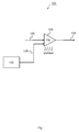
Fig. 1 illustrates a schematic block diagram of atransmitter apparatus 100 according to an embodiment. Thetransmitter apparatus 100 includes apreheating module 102 which is configured to preheat a power amplifier (PA) 104 before transmitting atransmit signal 106 using thepower amplifier 104. - In some embodiments the
transmitter apparatus 100 may be part of or coupled to a base station or a mobile terminal of a wireless communication system, such as Long-Term Evolution (LTE), for example. A base station may also be referred to as NodeB or eNodeB according to 3rd Generation Partnership Project (3GPP) terminology. A mobile terminal may also be referred to as User Equipment (UE). Although not limited thereto, embodiments may be particularly useful for wireless Time Division Duplex (TDD) systems, such as LTE TDD. In wireless TDD systems transmissions travel in both directions, uplink and downlink, on the same frequency band and separated in time. That is to say, time may be subdivided into downlink transmission time intervals, such as downlink slots, subframes, or frames, as well as uplink transmission time intervals, such as uplink slots, subframes, or frames. - In embodiments the
preheating module 102 may be configured to preheat thePA 104 in a preheat time interval between a first and a second transmission time interval, wherein the transmit signal is transmitted in or during the second transmission time interval. For TDD systems, for example, and when thetransmitter apparatus 100 is part of a base station, the preheat time interval may be during or in an uplink transmission time interval in between two consecutive downlink transmission time intervals. If thetransmitter apparatus 100 is part of a UE, the preheat time interval may also be during a downlink transmission time interval in between two consecutive uplink transmission time intervals. - The
PA 104 may be a Radio Frequency PA (RF-PA) for amplifying signals in the RF domain. Thereby the RF domain denotes a frequency range from several MHz to several GHz. For LTE TDD, for example, frequencies in the range of 2 GHz to 4 GHz are commonly used today. ThePA 104 may be used to convert a low-power RF signal 105 into alarger RF signal 106 of significant power, typically for driving an antenna (not shown) of thetransmitter apparatus 100. - The
PA 104 may include one or more transistors. For example, adequate transistors for RF PAs include Field Effect Transistors (FETs), such as high power RF Laterally Diffused Metal Oxide Semiconductor (LDMOS) transistors. During operation the PA's 104 temperature may change significantly due to flow of electrical currents. An electro-thermal model of a transistor may describe self-heating effects produced by junction temperature of the transistor varying with its instantaneous dissipated power. A simple thermal model for a device, such as a transistor, may include a thermal resistance Rth (°C/W) and a thermal capacitance Cth, (J/°C), for example. Similar to an electric time constant a thermal time constant τth may then be expressed by Rth and Cth, for example, τth = Rth * Cth. Hence, the thermal time constant τth may be regarded as the time required for a device to change 63.2% (1/e) of the total difference between its initial and final body temperature when subjected to a step function change in temperature, under zero power conditions. - The PA's 104 temperature, e.g. the junction temperature of the one or more transistors, may change significantly during operation. Electro-thermal memory effects caused by the temperature variations of the
PA 104 may negatively affect its distortion generation. The electro-thermal memory effects take place in a transient state. For instance when thePA 104 does not process or amplify any signal, it may cool-down very fast and when a new transmission arrives it takes τth until thePA 104 achieves its steady-state temperature again. In the steady-state the electro-thermal memory effects may be negligent. However, they may not be neglected in the transient state. Therefore themodule 102 may be configured to thermally stabilize thePA 104 by preheating thePA 104 before the transmission of the transmitsignal 106 starts. When the transmission of the actual transmitsignal 106 starts thePA 104 will then already substantially be in its thermal steady state. This may reduce undesired non-linearity effects of thePA 104 due to electro-thermal memory effects. - Hence, in embodiments the
preheating module 102 is configured to act on thePA 104 in order to bring it to or at least close to its thermal steady state. While in some embodiments the preheating may be performed by an external preheating device separate from thePA 104, such as a separate heater, other embodiments propose preheating thePA 104 by means of self-heating. Hence, the preheatingmodule 102 may be configured to preheat thePA 104 before transmitting the transmitsignal 106 by causing self-heating of thePA 104. As a result of the preheating thePA 104 will substantially be in thermal steady state when the transmission of the transmitsignal 106 starts. In thermal steady state the PA's gain curve has substantially no fluctuations (constant level) over time. Hence, in thermal steady state achieved by preheating thePA 104 may be regarded as a pure memoryless PA. - The preheating may take place shortly before the transmission of the transmit
signal 106 starts. Thereby the preheating time or period may be dependent on the thermal time constant τth of thePA 104, for example. In particular, the preheating time may be substantially equal to the PA's thermal time constant τth. In such embodiments thepreheating module 102 may be configured to determine the thermal time constant τth of thePA 104 prior to preheating thePA 104. This may be done by looking up the thermal time constant τth obtained from the PA's datasheet in an optional memory device of thetransmitter apparatus 100, for example. For another example, the thermal time constant τth may be determined by one or more measurements. - In some embodiments the
preheating module 102 may be configured to determine the thermal time constant τth based on a pulsed excitation of thePA 104. When performing pulsed excitation adequate signal pulses may be applied to thePA 104 in order to raise the PA's 104 body temperature well above that of the ambient. A pulse may be designed such that power is maintained until thermal stabilization of thePA 104 at the elevated temperature is achieved. Then the pulse is removed from thePA 104 and, simultaneously, a timer may be triggered. The thermal resistance of thePA 104 may be continuously monitored and when it indicates that thePA 104 has cooled to the temperature which represents 63.2% of the temperature difference between the elevated temperature and that of the ambient temperature, the timer may be stopped. The time indicated represents the thermal time constant τth and may usually be expressed in "seconds". For such measurements theapparatus 100 may optionally also comprise one or more temperature sensors for sensing the PA's temperature. - In some embodiments the preheating may start substantially τth seconds before the start of the actual transmission of the transmit
signal 106, which may be a downlink signal in a downlink transmission time interval (e.g. downlink frame), for example. In cases of self-heating, the preheatingmodule 102 may be configured to cause thePA 104 to amplify apredefined preheating signal 108 prior to the transmission of the transmitsignal 106. The predefined preheating signal may be a low-power RF signal and may comprise one or more known training symbols. A number of training symbols of thepredefined preheating signal 108 may be determined based on the thermal time constant τth. For example, the number of training symbols may for example be

signal 106. - If embodiments are applied to wireless communication systems, such as LTE TDD, the
predefined preheating signal 108 may be derived from standardized downlink or uplink test signals. In case of LTE the predefined preheating signal may be derived from the Evolved UMTS Terrestrial Radio Access (E-UTRA) Test Models (TM), for example E-TM1.1 or E-TM1.2. These are downlink, single-antenna port signals. However, other training signals are also possible. - The amplification of the
predefined preheating signal 108 by means of thePA 104 may take place at the highest amplification level or power level defined for transmitting the transmitsignal 106. Thepreheating module 102 may hence be configured to amplify the predefined preheating signal to the highest power level defined for transmitting the transmitsignal 106. This may enable to quickly reach the PA's 104 thermal steady state. Thereby the highest power level may vary from system to system. - Turning now to
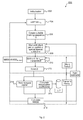
Fig. 2 , an embodiment of amethod 200 for thetransmitter apparatus 100 will be described. - The
method 200 is directed to improving linearization scheme performance in "silent" periods, for instance, time slots with no user traffic or uplink slots in LTE TDD systems. The linearization scheme performance is limited by the PA's 104 dynamic effects. Conventionally, in order to thermally stabilize thePA 104, a heat sink may be placed close to the device. Such solutions, however, do not avoid the dynamic effects at all, but may reduce its dynamic range. Another conventional solution would be to replace thePA 104 by a one with lower dynamic effects (usually an expensive one). - After an
initialization act 202, themethod 200 comprises an act 204 of estimating the PA's 104 thermal time constant τth. This may be done as has been described above. For example, estimating the thermal time constant τth may be triggered if non-linear effects of thePA 104 exceed a predefined threshold. A metric could be the so-called Normalized Mean Square Error (NMSE) between a forward signal travelling through thePA 104 and a feedback signal fed back from the PA's output. If the measured NMSE is larger than a NMSEthreshold (for example, -20dB) than estimating 204 the thermal time constant τth may be triggered. In some embodiments the forward signal and the feedback signal could be compared in the digital baseband domain, as will be described further below. - Further, the
method 200 comprises an act 206 of determining a suitable training sequence Ω for a preheating signal, the training sequence comprising nsymbols training symbols. For example, the training sequence Ω may be derived from E-UTRA Test Models, such as E-TM1.1 or E-TM1.2. Preheating of thePA 104 takes place in "silent" periods, which are periods where thetransmitter apparatus 100 usually does not send any downlink signals intended for associated UE's, for example. Similarly, silent periods are also available for the uplink in other embodiment. Inact 208 thetransmitter apparatus 100 waits for such a silent period, which may be an uplink frame or subframe, for example. As an example it may be assumed that a subframe comprises N symbols, i.e., the N = number of symbols per subframe. Starting from the beginning of the silent period (e.g. uplink subframe) thetransmitter apparatus 100 or themodule 102 may wait a time corresponding to (N - nsymbols ) symbols (see act 210) until the preheatingsignal 108 comprising the training sequence Ω is passed through the PA 104 (see act 212) in order to cause self-heating up to its thermal steady state. Note that the amplified preheating signal may be decoupled from an antenna in order not to cause interference on uplink signals, for example. Sending the preheatingsignal 108 lasts nsymbols symbols and is hence finished when the next "non-silent" transmit period starts, for example, a next downlink subframe. During the transmit period thetransmitter apparatus 100 may transmit adownlink signal 106 to associated UEs (see act 214). In order to compensate for power amplifier non-linearities the transmitapparatus 100 may predistort the downlink signal by calculating and applying linearization coefficients to the downlink signal prior to passing it through thePA 104. A difference between the amplifieddownlink signal 106 and the non-amplified downlink signal may be determined by means of feeding back the amplified downlink signal and calculating the NMSE between the forward signal and the feedback signal. - With the
method 200 it may be ensured that thePA 104 has reached its thermal steady state before the actual slot (downlink or transmit signal 106) is sent. - The
method 200 may be implemented by an embodiment of atransceiver apparatus 300 which is schematically illustrated inFig. 3 . Thetransceiver apparatus 300, which may be implemented in a Remote Radio Head (RRH), for example, comprises adigital baseband module 310 coupled to aRF module 320. An RF transmitsignal 306 output from theRF module 320 is bandpass filtered by abandpass filter 330 and then fed to anantenna 340 for transmission over a wireless medium. - A baseband
signal processing module 311 receives digital baseband samples via a Common Public Radio Interface (CPRI) to perform digital signal processing methods on the received signal samples. The digital baseband samples may be transmitted to a receiver during subsequent intermittent transmission time intervals, such as downlink subframes, for example. There may be silent periods, such as uplink subframes, between two consecutive subsequent transmission time intervals. During such silent periods atraining sequence module 302 may provide one or more known digital baseband training symbols Ω = {S 0, S 1 , ..., Snsymbols } for generating a preheating signal. Hence, thetraining sequence module 302 may also be interpreted as preheating module in this example. - Crest factor or peak-to-average ratio reduction may be performed on the digital baseband data provided by
modules 311 and/or 302 by a crestfactor reduction module 312 before the resulting peak-to-average ratio reduced digital baseband signal is digitally predistorted by Digital PreDistortion (DPD)module 314. Inphase (I) and Quadrature (Q) components of the digitally predistorted baseband signal are then digital to analog converted by Digital-to-Analog Converters (DACs) 321. The resulting analog baseband signal is then up-converted to the RF domain by an up-conversion circuit 322 to obtain a low-power RF signal. After passing an optionalanalog attenuator module 323 the low-power RF signal is amplified by RF-PA 104, filtered bybandpass filter 330 and then fed toantenna 340 for transmission. Therebymodule 323 may be considered as an analog power control to condition the IQ samples to the RF-PA input characteristic. - A receive path of
transceiver apparatus 300 comprises anRF bandpass filter 325, a Low Noise Amplifier (LNA) 326, a down-conversion circuit 327, and Analog-to-Digital Converters (ADCs) 328. TheLNA 326 may amplify the received signal, which may be received with a rather low level. AnRF feedback signal 335 may be converted back to the digital baseband domain and used to adjust the digital predistortion (see module 315) to a current nonlinear behavior of thePA 304. - In the example embodiment of
Fig. 3 , thermal memory effects of theRF PA 304 may be compensated / reduced by preheating theRF PA 304 via the training sequence Ω = {S 0, S 1, ..., Snsymbols } provided by thetraining sequence module 302 during silent periods between transmission time intervals. The duration of the training sequence Ω may correspond at least to the thermal time constant τth of theRF PA 304, such that theRF PA 304 may achieve its steady-state temperature after amplifying the preheating signal. That is to say, thermal stabilization of the RF-PA 304 before a DL slot in a LTE-TDD system or before a high user traffic frame is to be sent may be achieved. - To summarize, a PA preheating concept according to an embodiment comprises:
- determining the thermal time constant τth of the PA;
- calculating a number nsymbols of training symbols, each training symbol having a symbol duration Tsymbol:
- if τth > Tsymbol

- else
nsymbols = 1
- if τth > Tsymbol
- pick nsymbols of the training sequence Ω = {S 0, S 1, ..., S nsymbols} and amplify it with the highest available power level;
- send or amplify the training sequence Ω ={S 0, S 1, ..., S nsymbols} before actual slot.
- Embodiments may contribute to cost reduction and may improve transceiver products in terms of stability and reliability. Besides embodiments may ensure a faster PA stabilization as its dynamic effects may be removed or at least reduced. Embodiments may provide several dB higher suppression of spectral regrowth when compared with conventional PA linearization techniques.
- The description and drawings merely illustrate the principles of the invention. It will thus be appreciated that those skilled in the art will be able to devise various arrangements that, although not explicitly described or shown herein, embody the principles of the invention and are included within its spirit and scope. Furthermore, all examples recited herein are principally intended expressly to be only for pedagogical purposes to aid the reader in understanding the principles of the invention and the concepts contributed by the inventor(s) to furthering the art, and are to be construed as being without limitation to such specifically recited examples and conditions. Moreover, all statements herein reciting principles, aspects, and embodiments of the invention, as well as specific examples thereof, are intended to encompass equivalents thereof.
- Functional blocks shall be understood as functional blocks comprising circuitry that is adapted for performing a certain function, respectively. Hence, a "module for s.th." may as well be understood as a "module being adapted or suited for s.th.". A module being adapted for performing a certain function does, hence, not imply that such module necessarily is performing said function (at a given time instant).
- Functions of various elements shown in the figures, including any functional blocks may be provided through the use of dedicated hardware, such as "a processor", "a controller", etc. as well as hardware capable of executing software in association with appropriate software. Moreover, any entity described herein as functional block, may correspond to or be implemented as "one or more modules", "one or more devices", "one or more units", etc. When provided by a processor, the functions may be provided by a single dedicated processor, by a single shared processor, or by a plurality of individual processors, some of which may be shared. Moreover, explicit use of the term "processor" or "controller" should not be construed to refer exclusively to hardware capable of executing software, and may implicitly include, without limitation, digital signal processor (DSP) hardware, network processor, application specific integrated circuit (ASIC), field programmable gate array (FPGA), read only memory (ROM) for storing software, random access memory (RAM), and non-volatile storage. Other hardware, conventional and/or custom, may also be included.
- It should be appreciated by those skilled in the art that any block diagrams herein represent conceptual views of illustrative circuitry embodying the principles of the invention. Similarly, it will be appreciated that any flow charts, flow diagrams, state transition diagrams, pseudo code, and the like represent various processes which may be substantially represented in computer readable medium and so executed by a computer or processor, whether or not such computer or processor is explicitly shown.
- Furthermore, the following claims are hereby incorporated into the Detailed Description, where each claim may stand on its own as a separate embodiment. While each claim may stand on its own as a separate embodiment, it is to be noted that - although a dependent claim may refer in the claims to a specific combination with one or more other claims - other embodiments may also include a combination of the dependent claim with the subject matter of each other dependent claim. Such combinations are proposed herein unless it is stated that a specific combination is not intended. Furthermore, it is intended to include also features of a claim to any other independent claim even if this claim is not directly made dependent to the independent claim.
- It is further to be noted that methods disclosed in the specification or in the claims may be implemented by a device having means for performing each of the respective steps of these methods.
- Further, it is to be understood that the disclosure of multiple steps or functions disclosed in the specification or claims may not be construed as to be within the specific order. Therefore, the disclosure of multiple steps or functions will not limit these to a particular order unless such steps or functions are not interchangeable for technical reasons. Furthermore, in some embodiments a single step may include or may be broken into multiple sub steps. Such sub steps may be included and part of the disclosure of this single step unless explicitly excluded.
Claims (15)
- A transmitter (100; 300) apparatus, comprising:a preheating module (102; 302) to preheat a power amplifier (104; 304) before transmitting a transmit signal (106; 306) using the power amplifier (104; 304).
- The transmitter apparatus (100; 300) of claim 1, wherein the preheating module (102; 302) is configured to preheat the power amplifier (104; 304) in a preheat time interval between a first and a second transmission time interval, wherein the transmit signal is transmitted in the second transmission time interval.
- The transmitter apparatus (100; 300) of claim 2, wherein the preheat time interval is during an uplink transmission time interval, and wherein the first and the second transmission time interval correspond to a first and a second downlink transmission time interval.
- The transmitter apparatus (100; 300) of claim 1, wherein the preheating module (102; 302) is configured to preheat the power amplifier (104; 304) to approach a thermal steady state of the power amplifier (104; 304) before transmitting the transmit signal (106; 306).
- The transmitter apparatus (100; 300) of claim 1, wherein the preheating module (102; 302) is configured to amplify, using the power amplifier (104; 304), a predefined preheating signal (108) prior to the transmission of the transmit signal (106; 306).
- The transmitter apparatus (100; 300) of claim 5, wherein predefined preheating signal (108) comprises one or more training symbols.
- The transmitter apparatus (100; 300) of claim 5, wherein the preheating module (102; 302) is configured to amplify the predefined preheating signal (108) to the highest power level defined for transmitting the transmit signal (106; 306).
- The transmitter apparatus (100; 300) of claim 1, wherein the preheating module (102; 302) is configured to determine a thermal time constant of the power amplifier (104; 304) prior to preheating the power amplifier.
- The transmitter apparatus (100; 300) of claim 8, wherein the preheating module (102; 302) is configured to determine a thermal time constant based on pulsed excitation of the power amplifier (104; 304).
- The transmitter apparatus (100; 300) of claim 8, wherein the preheating module (102; 302) is configured to determine a number of training symbols of a predefined preheating signal (108) based on the thermal time constant.
- The transmitter apparatus (100; 300) of claim 10, wherein the number of training symbols is

- The transmitter apparatus (100; 300) of claim 1, wherein the power amplifier (104; 304) is a radio frequency signal power amplifier.
- The transmitter apparatus (100; 300) of claim 1, wherein the transmitter apparatus is part of a base station or a mobile terminal of a wireless communication system.
- The transmitter apparatus (100; 300) of claim 13, wherein the wireless communication system is a Long Term Evolution Time Division Duplex system.
- A method (200) for a transmitter (100; 300), the method comprising:preheating a power amplifier (104; 304) before transmitting, using the power amplifier (104; 304), a transmit signal (106; 306).
Priority Applications (1)
| Application Number | Priority Date | Filing Date | Title |
|---|---|---|---|
| EP13306639.9A EP2879293A1 (en) | 2013-11-29 | 2013-11-29 | Apparatuses and methods for reducing electro-thermal memory effects for power amplifiers |
Applications Claiming Priority (1)
| Application Number | Priority Date | Filing Date | Title |
|---|---|---|---|
| EP13306639.9A EP2879293A1 (en) | 2013-11-29 | 2013-11-29 | Apparatuses and methods for reducing electro-thermal memory effects for power amplifiers |
Publications (1)
| Publication Number | Publication Date |
|---|---|
| EP2879293A1 true EP2879293A1 (en) | 2015-06-03 |
Family
ID=49765436
Family Applications (1)
| Application Number | Title | Priority Date | Filing Date |
|---|---|---|---|
| EP13306639.9A Withdrawn EP2879293A1 (en) | 2013-11-29 | 2013-11-29 | Apparatuses and methods for reducing electro-thermal memory effects for power amplifiers |
Country Status (1)
| Country | Link |
|---|---|
| EP (1) | EP2879293A1 (en) |
Cited By (2)
| Publication number | Priority date | Publication date | Assignee | Title |
|---|---|---|---|---|
| WO2017199259A1 (en) * | 2016-05-18 | 2017-11-23 | Actelis Networks (Israel) Ltd. | Time-division duplexing signal booster |
| CN116054851A (en) * | 2023-03-07 | 2023-05-02 | 上海安其威微电子科技有限公司 | RF chip |
Citations (6)
| Publication number | Priority date | Publication date | Assignee | Title |
|---|---|---|---|---|
| US4317083A (en) * | 1979-03-19 | 1982-02-23 | Rca Corporation | Bias adjustment responsive to signal power |
| US5920808A (en) * | 1996-12-12 | 1999-07-06 | Glenayre Electronics, Inc. | Method and apparatus for reducing key-up distortion by pre-heating transistors |
| US6054894A (en) * | 1998-06-19 | 2000-04-25 | Datum Telegraphic Inc. | Digital control of a linc linear power amplifier |
| US6104917A (en) * | 1999-03-01 | 2000-08-15 | Nokia Networks Oy | Apparatus, and associated method, for maintaining circuitry of radio device above a threshold temperature |
| US20110128078A1 (en) * | 2009-12-02 | 2011-06-02 | Sige Semiconductor Inc. | System and Method of Prebias for Rapid Power Amplifier Response Correction |
| US20120286866A1 (en) * | 2011-05-13 | 2012-11-15 | Ahmad Khanifar | Amplifier performance stabilization through preparatory phase |
-
2013
- 2013-11-29 EP EP13306639.9A patent/EP2879293A1/en not_active Withdrawn
Patent Citations (6)
| Publication number | Priority date | Publication date | Assignee | Title |
|---|---|---|---|---|
| US4317083A (en) * | 1979-03-19 | 1982-02-23 | Rca Corporation | Bias adjustment responsive to signal power |
| US5920808A (en) * | 1996-12-12 | 1999-07-06 | Glenayre Electronics, Inc. | Method and apparatus for reducing key-up distortion by pre-heating transistors |
| US6054894A (en) * | 1998-06-19 | 2000-04-25 | Datum Telegraphic Inc. | Digital control of a linc linear power amplifier |
| US6104917A (en) * | 1999-03-01 | 2000-08-15 | Nokia Networks Oy | Apparatus, and associated method, for maintaining circuitry of radio device above a threshold temperature |
| US20110128078A1 (en) * | 2009-12-02 | 2011-06-02 | Sige Semiconductor Inc. | System and Method of Prebias for Rapid Power Amplifier Response Correction |
| US20120286866A1 (en) * | 2011-05-13 | 2012-11-15 | Ahmad Khanifar | Amplifier performance stabilization through preparatory phase |
Cited By (5)
| Publication number | Priority date | Publication date | Assignee | Title |
|---|---|---|---|---|
| WO2017199259A1 (en) * | 2016-05-18 | 2017-11-23 | Actelis Networks (Israel) Ltd. | Time-division duplexing signal booster |
| GB2556826A (en) * | 2016-05-18 | 2018-06-06 | Actelis Networks Israel Ltd | Time-division duplexing signal booster |
| GB2556826B (en) * | 2016-05-18 | 2019-02-20 | Actelis Networks Israel Ltd | Time-division duplexing signal booster |
| US11082090B2 (en) | 2016-05-18 | 2021-08-03 | Actelis Networks (Israel) Ltd. | Time-division duplexing signal booster |
| CN116054851A (en) * | 2023-03-07 | 2023-05-02 | 上海安其威微电子科技有限公司 | RF chip |
Similar Documents
| Publication | Publication Date | Title |
|---|---|---|
| EP3252949B1 (en) | Methods and devices for predistortion of signals | |
| US9450553B2 (en) | Apparatus and a method for amplifying a transmit signal | |
| EP3070839B1 (en) | Adjusting power amplifier stimuli based on output signals | |
| Molina et al. | Digital predistortion using lookup tables with linear interpolation and extrapolation: Direct least squares coefficient adaptation | |
| US9225308B2 (en) | Apparatus and method for amplifying a transmit signal or for determining values of a delay control parameter | |
| US10153794B2 (en) | Transmitter, communication unit and method for limiting spectral re-growth | |
| EP2741423B1 (en) | Digital pre-distortion processing method and apparatus | |
| US9325357B2 (en) | Wireless communication unit, integrated circuits and method for linearizing a transmitter signal | |
| JP6025965B2 (en) | Canceling crosstalk in multiband transceivers | |
| KR20140130619A (en) | Apparatus and method for enveloping tracking calibration | |
| US20120195392A1 (en) | Predistortion in split-mount wireless communication systems | |
| US20170135058A1 (en) | System and method for enhanced transmitter efficiency | |
| US20120314746A1 (en) | Controlling a Transmit Path Based on Monitored Error Vector Magnitude (EVM) Performance | |
| EP2826142B1 (en) | Architecture and the training method of a pa dpd system with space mapping applied in the predistorter | |
| US7983359B2 (en) | Synchronization techniques for polar transmitters | |
| KR20070095792A (en) | Method and apparatus for signal power ramp-up in communication transmission | |
| US9577592B2 (en) | Method and device for controlling a power amplifier configured to use nonlinearity correction and a power amplifier system | |
| WO2010008968A1 (en) | Digital predistortion in a multi transceiver system provided with a smart antenna array | |
| Liu et al. | Performance analysis of direct-learning digital predistortion with loop delay mismatch in wideband transmitters | |
| US11516054B2 (en) | Polar transmitter with feedthrough compensation | |
| EP2879293A1 (en) | Apparatuses and methods for reducing electro-thermal memory effects for power amplifiers | |
| US20140010330A1 (en) | Transmission device and transmission method | |
| CN101233683B (en) | Data processing method, transmitter, device, network element and base station | |
| Nair et al. | A comparative study on digital predistortion techniques for Doherty amplifier for LTE applications | |
| JP2005006326A (en) | Coefficient estimation method and apparatus |
Legal Events
| Date | Code | Title | Description |
|---|---|---|---|
| PUAI | Public reference made under article 153(3) epc to a published international application that has entered the european phase |
Free format text: ORIGINAL CODE: 0009012 |
|
| 17P | Request for examination filed |
Effective date: 20141110 |
|
| AK | Designated contracting states |
Kind code of ref document: A1 Designated state(s): AL AT BE BG CH CY CZ DE DK EE ES FI FR GB GR HR HU IE IS IT LI LT LU LV MC MK MT NL NO PL PT RO RS SE SI SK SM TR |
|
| AX | Request for extension of the european patent |
Extension state: BA ME |
|
| 17Q | First examination report despatched |
Effective date: 20150521 |
|
| RBV | Designated contracting states (corrected) |
Designated state(s): AL AT BE BG CH CY CZ DE DK EE ES FI FR GB GR HR HU IE IS IT LI LT LU LV MC MK MT NL NO PL PT RO RS SE SI SK SM TR |
|
| STAA | Information on the status of an ep patent application or granted ep patent |
Free format text: STATUS: EXAMINATION IS IN PROGRESS |
|
| RAP1 | Party data changed (applicant data changed or rights of an application transferred) |
Owner name: ALCATEL LUCENT |
|
| GRAP | Despatch of communication of intention to grant a patent |
Free format text: ORIGINAL CODE: EPIDOSNIGR1 |
|
| STAA | Information on the status of an ep patent application or granted ep patent |
Free format text: STATUS: GRANT OF PATENT IS INTENDED |
|
| INTG | Intention to grant announced |
Effective date: 20180523 |
|
| STAA | Information on the status of an ep patent application or granted ep patent |
Free format text: STATUS: THE APPLICATION IS DEEMED TO BE WITHDRAWN |
|
| 18D | Application deemed to be withdrawn |
Effective date: 20181003 |