EP2879252A1 - Raceway for fastening, guiding and/or protecting electric cable means - Google Patents
Raceway for fastening, guiding and/or protecting electric cable means Download PDFInfo
- Publication number
- EP2879252A1 EP2879252A1 EP13400031.4A EP13400031A EP2879252A1 EP 2879252 A1 EP2879252 A1 EP 2879252A1 EP 13400031 A EP13400031 A EP 13400031A EP 2879252 A1 EP2879252 A1 EP 2879252A1
- Authority
- EP
- European Patent Office
- Prior art keywords
- channel sections
- raceway
- element means
- essentially
- base wall
- Prior art date
- Legal status (The legal status is an assumption and is not a legal conclusion. Google has not performed a legal analysis and makes no representation as to the accuracy of the status listed.)
- Granted
Links
Images


Classifications
-
- B—PERFORMING OPERATIONS; TRANSPORTING
- B60—VEHICLES IN GENERAL
- B60R—VEHICLES, VEHICLE FITTINGS, OR VEHICLE PARTS, NOT OTHERWISE PROVIDED FOR
- B60R16/00—Electric or fluid circuits specially adapted for vehicles and not otherwise provided for; Arrangement of elements of electric or fluid circuits specially adapted for vehicles and not otherwise provided for
- B60R16/02—Electric or fluid circuits specially adapted for vehicles and not otherwise provided for; Arrangement of elements of electric or fluid circuits specially adapted for vehicles and not otherwise provided for electric constitutive elements
- B60R16/0207—Wire harnesses
- B60R16/0215—Protecting, fastening and routing means therefor
-
- H—ELECTRICITY
- H02—GENERATION; CONVERSION OR DISTRIBUTION OF ELECTRIC POWER
- H02G—INSTALLATION OF ELECTRIC CABLES OR LINES, OR OF COMBINED OPTICAL AND ELECTRIC CABLES OR LINES
- H02G3/00—Installations of electric cables or lines or protective tubing therefor in or on buildings, equivalent structures or vehicles
- H02G3/02—Details
- H02G3/06—Joints for connecting lengths of protective tubing or channels, to each other or to casings, e.g. to distribution boxes; Ensuring electrical continuity in the joint
- H02G3/0608—Joints for connecting non cylindrical conduits, e.g. channels
-
- H—ELECTRICITY
- H02—GENERATION; CONVERSION OR DISTRIBUTION OF ELECTRIC POWER
- H02G—INSTALLATION OF ELECTRIC CABLES OR LINES, OR OF COMBINED OPTICAL AND ELECTRIC CABLES OR LINES
- H02G3/00—Installations of electric cables or lines or protective tubing therefor in or on buildings, equivalent structures or vehicles
- H02G3/02—Details
- H02G3/04—Protective tubing or conduits, e.g. cable ladders or cable troughs
- H02G3/0437—Channels
-
- H—ELECTRICITY
- H02—GENERATION; CONVERSION OR DISTRIBUTION OF ELECTRIC POWER
- H02G—INSTALLATION OF ELECTRIC CABLES OR LINES, OR OF COMBINED OPTICAL AND ELECTRIC CABLES OR LINES
- H02G3/00—Installations of electric cables or lines or protective tubing therefor in or on buildings, equivalent structures or vehicles
- H02G3/02—Details
- H02G3/06—Joints for connecting lengths of protective tubing or channels, to each other or to casings, e.g. to distribution boxes; Ensuring electrical continuity in the joint
Definitions
- the invention is related to a raceway for fastening, guiding and protecting electric cable means with the features of the preamble of claim 1.
- the invention relates more particularly to the installation of the cabling on aircraft doors, in particular airplanes passenger doors or airplanes cargo doors.
- Vehicles including automobiles, trucks, watercraft, and aircraft, have included electrical cabling for over a century.
- installation of these cables can be tedious and inefficient, due to the requirements of space, weight, and the amount of cabling required.
- a modem airplane or ship may have more than a hundred miles of electrical wiring.
- CFRP Carbon Fibre Reinforced Plastics
- the electric cable installation in doors i. e. the electrical harness is also exposed to mechanical caused damages, among others since door areas are zones of higher risk of abusive load application.
- abusive loads are a big issue since the electrical harnesses are well accessible and are often abused as handle bars.
- Some standard parts such as support clamps for electric cables provide for some protection against current injection but imply many drilling holes on CFRP structures and are not suited for mechanical protection. Harnesses provide for mechanical and/or electrical protection without any solution for the number of drilling holes on CFRP structures.
- the document US 3792189 A discloses a raceway for housing and protecting electric cable means along structural parts.
- the raceway comprises at least two essentially longitudinal housings each with a base wall integral with essentially parallel side walls. Said base wall and said side walls provide a cable canal open at opposed ends of each of said at least two essentially longitudinal housings.
- Said at least two essentially longitudinal housings are movable telescopically into one another at said open end by means of complementary male element or female element means and each of said essentially longitudinal housings is provided with at least one fixation bolt to the housing.
- the document GB 200324766 A discloses a device providing a protective sleeve around a bundle of one or more cables and bridging gaps between raceway sections.
- the device comprises a substantially flat, bendable web portion, having at least one opening adjacent one edge and a guide, slidable through the at least one opening, projecting from the opposite edge.
- the device is preferably formed from a single component, and is formed from PTFE.
- the document US5271585 discloses a fiber optics cable raceway formed of main channel members and telescope members.
- the main channel members have a generally U-shaped cross-section with a base, sides, and, at the top, inwardly extending lips.
- the telescope members have the same cross- section, but are slightly larger so they can fit about the main channel members for a longitudinally sliding fit.
- Small locking clips can then be fitted about the respective overlapping lips of two members to prevent further sliding.
- the raceway can be installed below the floor by the use of brackets hanging on pre-existing floor-supporting pedestals. It can be installed above a dropped ceiling by the use of hangers clamped to the grid struts of the ceiling.
- the locking clips serve to electrically interconnect the channel members and the telescope members.
- the solution is provided with a raceway for electric cable means with the features of claim 1 of the invention.
- a further solution is provided with a method of mounting said raceway to a structural part and mounting the electric cable means into the raceway with the features of claim 9 of the invention.
- Preferred embodiments of the invention are provided with the subclaims.
- a raceway for fastening, guiding and/or protecting electric cable means along or on top of structural parts, particularly along or on top of structural parts of an aircraft comprises at least two channel modules each with essentially longitudinal channel sections with a base wall integral with essentially parallel side walls. Said base wall and said side walls provide a channel section open at both ends of each of said at least two essentially longitudinal channel sections. Said at least two essentially longitudinal channel sections are movable telescopically during installation, into one another at said open ends by means of complementary male element or female element means.
- Each of said essentially longitudinal channel sections is provided with at least one fixation bolt for fixation of the at least two essentially longitudinal channel sections relative to each other and to the structural parts while at least one of said essentially longitudinal channel sections is provided with at least two fixation bolts for fixation of the at least two essentially longitudinal channel sections relative to each other and to the structural parts.
- Said at least one essentially longitudinal channel section provided with at least two fixation bolts for fixation of the at least two essentially longitudinal channel sections relative to each other and to the structural parts is preferably arranged at an end of the inventive raceway.
- the invention provides a raceway for fastening, guiding and protecting electric cable means that allows the installation of the raceway itself on the structural parts and the installation of the electric cables, e. g.
- the invention provides maximal protection properties for the electric cable combined with less required attachment provisions to any CFRP structure and reduced assembling effort in general.
- said male element means are projecting from a part of an open end of one essentially longitudinal channel section and said female element means are spared from a part of an open end of an opposed essentially longitudinal channel section, said essentially longitudinal channel sections being made of thermoplastic material.
- the inventive raceway provides extended mechanical protection for any electric cable mounted inside the channel section and continued electrical isolation due to the use of thermoplastics, e.g. the use of isolating polymers and the overlapping of the channel sections.
- the inventive raceway provides for the minimized attachment effort with less holes and attachment parts, e. g. rivets, bolts, etc. and the inventive raceway thus avoids disrupted fibres in CFRP structures caused by drilling holes and cut outs. Consequently the inventive raceway limits the deterioration of the strength properties of the concerned CFRP structures by avoiding drilling holes and cut outs for cable through routing on CFRP structures. As a consequence the invention provides potential for structural weight reduction of the concerned CFRP structures. Any rotation of a channel section of the inventive raceway is locked by means of just one fixation bolt plus the fixation by the neighbouring channel sections.
- the neighbouring parts lock each other except preferably at the start/end of a line of a channel section, conducted straight or curved, where at least one additional fixation bolt is needed for rotation locking of said channel section.
- the routing of the inventive raceway - straight or curved - is totally controllable over lifetime and sagging and/or swelling is not an issue at all.
- the inventive raceway provides a modular system with regard to parameters such as size, length and material to cover the needs of different geometrical environments with a low number of different channel sections, said channel sections being easily processible.
- the inventive raceway allows compensation of significant in/decrease of length depending on the material humidity and the used thermoplastic material due to the telescopic feature providing compensation for unintentionally elongated or shortened channel sections.
- the inventive raceway avoids the risk of current injection caused by damaged cable insulation or cut cables even if said cables are close to the CFRP parts of the aircraft, and thus prevents undetected structural damages; e.g. loss of matrix integrity by heat induction.
- the inventive raceway further avoids load application directly to the harness by surrounding rigid channel sections with a base wall and side walls adapted to the cable means along the inside of the channel sections.
- the inventive raceway provides fixation, mechanical and electrical protection at once without additional line guidance with the advantage of reduced weight, reduced assembling effort and low mounting effort for the cables onto the raceway.
- pairwise slots are integrated for electric cable/harness fixation to the channel sections by tying means.
- the pairwise slots are distant to each other along the channel sections of the inventive raceway.
- said complementary male element and female element means are provided with telescopic length compensation while continuous electrical and mechanical protection is provided because of the overlapping telescope principle on one side combined with one bolt fixation at the opposite side of the channel section.
- one fixation hole is mounted inside essentially straight channel sections through said base wall of each essentially longitudinal channel section, whereas curved or straight channel sections and channel sections at ends of the inventive raceway are provided with two fixation holes i. e. one fixation hole next to each of two ends of curved or straight and end channel sections.
- a method of mounting the raceways to the structural part and mounting the electric cable means into the raceway comprises the steps of: - Providing tying means, e. g. plastic clips, with free ends, - Providing channel sections with pairwise slots respectively next to each of side walls through the base wall to a clearance in the base wall, each of said channel sections having female element means and male element means at opposed ends, - Passing the free ends from the clearance through each of the pairwise slots and extending said free ends towards the open top of the channel sections, - Mounting at least two of said essentially longitudinal channel sections with one passed through plastic clip per pairwise slot along or on top of the structural part while compensating length variations by inserting the female element means more or less far into the male element means, - Mounting each of the respective channel sections after fixation through the at least one hole to or on top of the structural part, - Inserting the electric cable means along the raceway through the open top into the longitudinal channel sections between the free ends of the plastic clips, and - Joining and
- a raceway 1 comprises a channel module 2 with two channel sections 2 A , 2 B aligned along a common longitudinal axis and facing each other with respective ends at a junction area 6.
- the two channel sections 2 A , 2 B are made of polyamide or any other thermoplastic material.
- the respective ends are essentially planar, rectangular and perpendicular with regard to the common longitudinal axis of the two channel sections 2 A , 2 B .
- the channel sections 2 A , 2 B extend essentially longitudinally including curved and bifurcated shapes. E. g. a curved channel section 2 A , 2 B encloses an angle of 90°.
- Essentially cubic male element means 3 are provided at one end of the channel section 2 A .
- Corresponding cubic female element means 4 as a complement to the essentially cubic male element means 3 are provided at the end of channel section 2 B .
- the channel sections 2 A , 2 B are each provided with cubic female element means 4 at one end and complementary cubic male element means 3 at the opposed end for the provision of a modular construction system.
- a hole 5 for a fixation bolt (not shown) with a diameter of 4 - 7 mm is provided in a base wall 7 for fixation of each of the channel sections 2 A , 2 B to a structural part, particularly for fixation along at least a door of an aircraft (not shown).
- a clearance 12 essentially parallel to and below the base wall 7 is provided for tying means (not shown) for withholding electric cable means 10 (see Fig. 2 ) inside the channel sections 2a, 2b.
- Each of the two channel sections 2 A , 2 B are formed by the base wall 7 and side walls 8, 9 raising essentially rectangular with regard to the base wall 7.
- the side walls 8, 9 leave the channel sections 2 A , 2 B open towards the top.
- the base wall 7 closes the channel sections 2 A , 2 B towards the bottom except for pairwise slots 11 opening passages inside the channel sections 2 A , 2 B through the base wall 7 respectively next to the side walls 8, 9 for the tying means to the clearance 12 below the base wall 7.
- the channel sections 2 A , 2 B are shaped semi circular between the base wall 7 and the side walls 8, 9 for a proper fitting of electric cable means 10 with an essentially circular cross section for insertion inside the channel sections 2 A , 2 B .
- the cable means 10 are a single cable in a harness (not shown), a bundle of cables in a harness (not shown) or a bundle of harnessed cables (not shown).
- a harness diameter ranges from 2-50 mm or preferably from 5 - 20 mm.
- the channel section 2 A is formed by the base wall 7 and the side walls 8, 9 raising essentially rectangular with regard to the base wall 7 for provision of a channel section open at both ends of each of said at least two essentially longitudinal channel sections 2 A , 2 B .
- Essentially cubic male element means 3 are provided from one end of the channel section 2 A at the bottom along a central section of the base wall 7. Pairwise slots 11 inside the channel sections 2 A , 2 B through the base wall 7 are respectively located next to the side walls 8, 9 for the tying means to the clearance 12 below the base wall 7 (see as well Fig. 4 ).
- the channel section 2 B is formed by the base wall 7 and side walls 8, 9 raising essentially rectangular with regard to the base wall 7 for provision of a channel section open at both ends of each of said at least two essentially longitudinal channel sections 2 A , 2 B .
- the essentially rectangular female element means 4 is provided in one end of the channel section 2 B at the bottom along a central section of the base wall 7 adapted for accommodation of the essentially rectangular male element means 3.
- a preferred channel module 16 comprises two further channel sections 15 A , 15 B for alignment along a common longitudinal axis and facing each other with respective ends at the junction area 6.
- the two further channel sections 15 A , 15 B are made of polyamide or any other thermoplastic material.
- the respective ends are essentially planar, rectangular and perpendicular with regard to the common longitudinal axis of the two further channel sections 15 A , 15 B .
- Essentially u-shaped female element means 13 are provided at one end of the further channel section 15A.
- Correspondingly u-shaped male element means 14 (see as well Fig. 9 ) as a complement to the essentially cubic female element means 13 are provided at the end of the further channel section 15 B .
- the further channel sections 15 A , 15 B are each provided with u-shaped female element means 4 at one end and complementary u-shaped male element means 3 at the opposed end for the provision of a modular construction system.
- a hole 5 for a fixation bolt (not shown) with a diameter of 4 - 7 mm is provided in the base wall 7 for fixation of each of the further channel sections 15 A , 15 B to a structural part 17, particularly for fixation along at least a door of an aircraft (not shown).
- the clearance 12 essentially parallel to and below the base wall 7 is provided for tying means (not shown) for withholding electric cable means 10 (see Fig. 6, 7 ) inside the further channel sections 15a, 15b.
- Each of the two further channel sections 15 A , 15 B are formed by the base wall 7 and side walls 8, 9 raising essentially rectangular with regard to the base wall 7.
- the side walls 8, 9 leave the further channel sections 15 A , 15 B open towards the top.
- the base wall 7 closes the further channel sections 15 A , 15 B towards the bottom except for pairwise slots 11 opening passages inside the further channel sections 15 A , 15 B through the base wall 7 respectively next to the side walls 8, 9 for the tying means to the clearance 12 below the base wall 7.
- the further channel sections 15 A , 15 B are shaped semi circular between the base wall 7 and the side walls 8, 9 for a proper fitting of the electric cable means 10 with an essentially circular cross section for insertion inside the further channel sections 15 A , 15 B .
- the further channel section 15 B is formed by the base wall 7 and side walls 8, 9 raising essentially rectangular with regard to the base wall 7 for provision of a channel section open at both ends of each of said at least two essentially longitudinal channel sections 15 A , 15 B .
- Essentially rectangular u-shaped female element means 13 are spared longitudinally along a section of the outside of the base wall 7 and the side walls 8, 9 of the further channel section 15 A for accommodation of essentially rectangular u-shaped male element means 14.
- the further channel section 15 A is formed by the base wall 7 and the side walls 8, 9 raising essentially rectangular with regard to the base wall 7 for provision of a channel section open at both ends of each of said at least two essentially longitudinal further channel sections 15 A , 15 B .
- Essentially rectangular u-shaped male element means 14 project longitudinally from one end of the further channel section 15 B with a set off from the outer circumference of the further channel section 15 B .
- One of the pairwise slots 11 inside the further channel section 15 B passes through the base wall 7 next to the side wall 9 for the tying means to the clearance 12 below the base wall 7 (see as well Fig. 5, 7 ).
- Each of two still further channel sections 19 A , 19 B of another channel module 18 are formed by the base wall 7 and side walls 8, 9 raising essentially rectangular with regard to the base wall 7.
- the further channel section 19 B is provided with rounded u-shaped male element means 23 projecting longitudinally from one end of the further channel section 19 B with a set off from the outer circumference of the further channel section 19 B .
- Essentially rounded u-shaped female element means 22 are spared longitudinally along a section of the outside of the base wall 7 and the side walls 8, 9 of the further channel section 19 A for accommodation of the essentially rectangular male element means 23.
- Still another channel module 20 comprises two channel sections 21 A , 21 B aligned along the common longitudinal axis and facing each other with respective ends at the junction area 6.
- the two channel sections 21 A , 21 B are made of polyamide or any other thermoplastic material.
- the respective ends are essentially planar, rectangular and perpendicular with regard to the common longitudinal axis of the two channel sections 21 A , 21 B .
- Essentially fork type male element means 24 are provided at one end of the channel section 21 A .
- Corresponding nose type female element means 25 as a complement to the essentially fork type male element means 24 are provided at the end of channel section 21 B .
- the channel sections 21 A , 21 B are each provided with fork type male element means 24 at one end and complementary nose type female element means 25 at the opposed end for the provision of a modular construction system for the raceway 20.
- Fig. 17 corresponding features are referred to with the references of Fig. 1-16 .
- the channel modules 2, 16, 18, 20 for insertion in an inclined position of any of the raceways 1 are straight with one fixation hole 5 each next to one end.
- the channel sections 2 A , 2 B , 19 A , 19 B , 21 A , 21 B are respectively provided with male element means 3, 14, 23 or 25 at one end and complementary female element means 4, 13, 22, 24 at the opposed end.
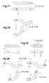
- Fig. 18 corresponding features are referred to with the references of Fig. 1-17 .
- the channel modules 2, 16, 18 or 20 for insertion in an inclined position of any of the raceways 1 are curved with one or more arcs and with one fixation hole 5 each next to one end.
- the channel sections 2 A , 2 B , 19 A , 19 B , 21 A , 21 B are respectively provided with male element means 3, 14, 23 or 25 at one end and complementary female element means 4, 13, 22, 24 at the opposed end.
- Fig. 19 corresponding features are referred to with the references of Fig. 1-18 .
- the channel modules 2, 16, 18, 20 for insertion in an end position of any of the raceways 1 are straight with one or two fixation holes 5 each next to one end.
- the channel sections 2 A , 2 B , 19 A , 19 B , 21 A , 21 B are provided with male element means 3, 14, 23 or 25 or complementary female element means 4, 13, 22, 24 at one end.
- Fig. 20 corresponding features are referred to with the references of Fig. 1-19 .
- the channel modules 2, 16, 18 or 20 for insertion in an end position of any of the raceways 1 are curved with one or more arcs and with one or two fixation holes 5 each next to one end.
- the channel sections 2 A , 2 B , 19 A , 19 B , 21 A , 21 B are respectively provided with male element means 3, 14, 23 or 25 or complementary female element means 4, 13, 22, 24 at one end.
- the channel modules 2, 16, 18 or 20 with compatible channel sections 2 A , 2 B , 19 A , 19 B , 21 A , 21 B are suitable for combination with each other to raceways 1 of different designs. Free ends of the tying means are passed from the clearance 12 through each of the pairwise slots 11 of each of the channel modules 2, 16, 18 or 20, said free ends extending towards the open top of the channel sections 2 A , 2 B , 15 A , 15 B .
- the at least two essentially longitudinal channel sections 2 A , 2 B , 15 A , 15 B with one passed through tying means per pairwise slot 11 are mounted along or on top of the structural part 17 according to e. g. a routing diagram.
- the telescopic junctions 6 allow compensation of length variations by inserting the female element means 4, 14 more or less far into the cubic male element means 13 of the respective channel sections 2 A , 2 B , 15 A , 15 B .
- each of the longitudinal channel sections 2 A , 2 B , 15 A , 15 B are mounted by a fixation bolt through the hole 5 to or on top of the structural part 17 whereby the fixation with one bolt through one hole 5 per longitudinal channel section 2 A , 2 B , 15 A , 15 B allows further rotational adaption of the longitudinal channel sections 2 A , 2 B , 15 A , 15 B to the structural part 17.
- Longitudinal channel sections 2 A , 2 B , 15 A , 15 B with respectively two holes 5 for a fixation bolt at each end of the raceway 1 are provided for curved channel sections 2 A , 2 B , 15 A , 15 B . If a curved part is localized in the middle of the raceway 1 only one hole 5 is sufficient for attachment.
- the electric cable means 10 are inserted along the raceway 1 through the open top into the longitudinal channel sections 2 A , 2 B , 15 A , 15 B between the free ends of the plastic clips.
- the free ends of the plastic clips are joined above the inserted electric cable means 10 and tightened to retain the electric cable means 10 inside the longitudinal channel sections 2A, 2B, 15A, 15B.
Landscapes
- Engineering & Computer Science (AREA)
- Architecture (AREA)
- Civil Engineering (AREA)
- Structural Engineering (AREA)
- Mechanical Engineering (AREA)
- Installation Of Indoor Wiring (AREA)
- Details Of Indoor Wiring (AREA)
Abstract
Description
- The invention is related to a raceway for fastening, guiding and protecting electric cable means with the features of the preamble of
claim 1. The invention relates more particularly to the installation of the cabling on aircraft doors, in particular airplanes passenger doors or airplanes cargo doors. - Vehicles, including automobiles, trucks, watercraft, and aircraft, have included electrical cabling for over a century. However, installation of these cables can be tedious and inefficient, due to the requirements of space, weight, and the amount of cabling required. For example, a modem airplane or ship may have more than a hundred miles of electrical wiring.
- Composites, in particularly Carbon Fibre Reinforced Plastics (CFRP) are applied extensively throughout the fuselage of recently developed airplanes. This extensive use of CFRP raises problems, also relevant looking at the installation of electrical harnesses.
- The document "Design guidelines: Design Guidelines for Shielding Effectiveness, Current Carrying Capability, and the Enhancement of Conductivity of Composite Materials", NASA Contractor Report 4784, R.W. Evans, Tec-Masters, Inc. • Huntsville, Alabama; August 1997" discloses risks of current injection into fiber reinforced composites parts (FRP) caused by damaged insulations of electric cables or cut electric cables where the routing of said cables is close to CFRP parts, leading most likely to undetected structural damages of the FRP and electric cables; e.g. loss of matrix integrity by heat induction.
- The electric cable installation in doors, i. e. the electrical harness is also exposed to mechanical caused damages, among others since door areas are zones of higher risk of abusive load application. Especially for cargo doors and in cargo loading areas, abusive loads are a big issue since the electrical harnesses are well accessible and are often abused as handle bars.
- Drilling holes and cut outs lead to disrupted fibres in CFRP structures. Said disrupted fibres cause losses in the strength properties of the CFRP structures and are cost increasing too, due to machining time and drilling tool deterioration. Therefore, drilling holes and cut outs for cable through routing should be avoided or at least reduced on CFRP structures, especially in areas, where the structure is highly loaded. Equally high numbers of rivets, needed for known harness fastening, destroy the carbon fibres.
- Some standard parts, such as support clamps for electric cables provide for some protection against current injection but imply many drilling holes on CFRP structures and are not suited for mechanical protection. Harnesses provide for mechanical and/or electrical protection without any solution for the number of drilling holes on CFRP structures.
- The document
US 3792189 A discloses a raceway for housing and protecting electric cable means along structural parts. The raceway comprises at least two essentially longitudinal housings each with a base wall integral with essentially parallel side walls. Said base wall and said side walls provide a cable canal open at opposed ends of each of said at least two essentially longitudinal housings. Said at least two essentially longitudinal housings are movable telescopically into one another at said open end by means of complementary male element or female element means and each of said essentially longitudinal housings is provided with at least one fixation bolt to the housing. - The document
GB 200324766 A - The document
US5271585 discloses a fiber optics cable raceway formed of main channel members and telescope members. The main channel members have a generally U-shaped cross-section with a base, sides, and, at the top, inwardly extending lips. The telescope members have the same cross- section, but are slightly larger so they can fit about the main channel members for a longitudinally sliding fit. By alternately, interfitting main members and telescope members and adjusting the length by telescopic sliding, a raceway of the desired length can quickly be assembled. Small locking clips can then be fitted about the respective overlapping lips of two members to prevent further sliding. The raceway can be installed below the floor by the use of brackets hanging on pre-existing floor-supporting pedestals. It can be installed above a dropped ceiling by the use of hangers clamped to the grid struts of the ceiling. The locking clips serve to electrically interconnect the channel members and the telescope members. - It is an objective of the invention to provide an improved raceway for protecting electric cable means with less required attachment provisions. It is a further objective of the invention to provide a method of mounting said raceway to a structural part and of mounting the electric cable means into the raceway.
- The solution is provided with a raceway for electric cable means with the features of
claim 1 of the invention. A further solution is provided with a method of mounting said raceway to a structural part and mounting the electric cable means into the raceway with the features ofclaim 9 of the invention. Preferred embodiments of the invention are provided with the subclaims. - According to the invention a raceway for fastening, guiding and/or protecting electric cable means along or on top of structural parts, particularly along or on top of structural parts of an aircraft, comprises at least two channel modules each with essentially longitudinal channel sections with a base wall integral with essentially parallel side walls. Said base wall and said side walls provide a channel section open at both ends of each of said at least two essentially longitudinal channel sections. Said at least two essentially longitudinal channel sections are movable telescopically during installation, into one another at said open ends by means of complementary male element or female element means. Each of said essentially longitudinal channel sections is provided with at least one fixation bolt for fixation of the at least two essentially longitudinal channel sections relative to each other and to the structural parts while at least one of said essentially longitudinal channel sections is provided with at least two fixation bolts for fixation of the at least two essentially longitudinal channel sections relative to each other and to the structural parts. Said at least one essentially longitudinal channel section provided with at least two fixation bolts for fixation of the at least two essentially longitudinal channel sections relative to each other and to the structural parts is preferably arranged at an end of the inventive raceway. The invention provides a raceway for fastening, guiding and protecting electric cable means that allows the installation of the raceway itself on the structural parts and the installation of the electric cables, e. g. as harnesses, in the at least two essentially longitudinal channel sections with comparatively low effort and easens the maintenance of the harness of said electric cables. The invention provides maximal protection properties for the electric cable combined with less required attachment provisions to any CFRP structure and reduced assembling effort in general. According to a further aspect of the invention said male element means are projecting from a part of an open end of one essentially longitudinal channel section and said female element means are spared from a part of an open end of an opposed essentially longitudinal channel section, said essentially longitudinal channel sections being made of thermoplastic material. The inventive raceway provides extended mechanical protection for any electric cable mounted inside the channel section and continued electrical isolation due to the use of thermoplastics, e.g. the use of isolating polymers and the overlapping of the channel sections. The inventive raceway provides for the minimized attachment effort with less holes and attachment parts, e. g. rivets, bolts, etc. and the inventive raceway thus avoids disrupted fibres in CFRP structures caused by drilling holes and cut outs. Consequently the inventive raceway limits the deterioration of the strength properties of the concerned CFRP structures by avoiding drilling holes and cut outs for cable through routing on CFRP structures. As a consequence the invention provides potential for structural weight reduction of the concerned CFRP structures. Any rotation of a channel section of the inventive raceway is locked by means of just one fixation bolt plus the fixation by the neighbouring channel sections. In that way the neighbouring parts lock each other except preferably at the start/end of a line of a channel section, conducted straight or curved, where at least one additional fixation bolt is needed for rotation locking of said channel section. The routing of the inventive raceway - straight or curved - is totally controllable over lifetime and sagging and/or swelling is not an issue at all. The inventive raceway provides a modular system with regard to parameters such as size, length and material to cover the needs of different geometrical environments with a low number of different channel sections, said channel sections being easily processible. The inventive raceway allows compensation of significant in/decrease of length depending on the material humidity and the used thermoplastic material due to the telescopic feature providing compensation for unintentionally elongated or shortened channel sections. The inventive raceway avoids the risk of current injection caused by damaged cable insulation or cut cables even if said cables are close to the CFRP parts of the aircraft, and thus prevents undetected structural damages; e.g. loss of matrix integrity by heat induction. The inventive raceway further avoids load application directly to the harness by surrounding rigid channel sections with a base wall and side walls adapted to the cable means along the inside of the channel sections. The inventive raceway provides fixation, mechanical and electrical protection at once without additional line guidance with the advantage of reduced weight, reduced assembling effort and low mounting effort for the cables onto the raceway.
- Along the channel sections of the inventive raceway pairwise slots are integrated for electric cable/harness fixation to the channel sections by tying means. The pairwise slots are distant to each other along the channel sections of the inventive raceway.
- According to a preferred embodiment of the invention said complementary male element and female element means are provided with telescopic length compensation while continuous electrical and mechanical protection is provided because of the overlapping telescope principle on one side combined with one bolt fixation at the opposite side of the channel section.
- According to a still further aspect of the invention preferably one fixation hole is mounted inside essentially straight channel sections through said base wall of each essentially longitudinal channel section, whereas curved or straight channel sections and channel sections at ends of the inventive raceway are provided with two fixation holes i. e. one fixation hole next to each of two ends of curved or straight and end channel sections.
- According to a preferred embodiment of the invention a method of mounting the raceways to the structural part and mounting the electric cable means into the raceway comprises the steps of: - Providing tying means, e. g. plastic clips, with free ends, - Providing channel sections with pairwise slots respectively next to each of side walls through the base wall to a clearance in the base wall, each of said channel sections having female element means and male element means at opposed ends, - Passing the free ends from the clearance through each of the pairwise slots and extending said free ends towards the open top of the channel sections, - Mounting at least two of said essentially longitudinal channel sections with one passed through plastic clip per pairwise slot along or on top of the structural part while compensating length variations by inserting the female element means more or less far into the male element means, - Mounting each of the respective channel sections after fixation through the at least one hole to or on top of the structural part, - Inserting the electric cable means along the raceway through the open top into the longitudinal channel sections between the free ends of the plastic clips, and - Joining and tightening the free ends of the tying means about the electric cable means. The inventive method allows particularly cost efficient mounting of composite raceways with enhanced adaption potential at reduced constructive effort, said raceway fastening, guiding and protecting electric cable means mounted inside the longitudinal channel sections.
- Preferred embodiments of the invention are presented by means of the following description with reference to the attached drawings, from which in
-
Figure 1 a lateral view of two channel sections of a raceway according to the invention is shown, -
Figure 2 a cross-sectional view of one channel section of the raceway ofFig. 1 is shown, -
Figure 3 a perspective view of one channel section with male element means of the raceway ofFig. 1 is shown,Figure 4 a perspective view of one channel section with female element means of the raceway ofFig. 1 is shown, -
Figure 5 a lateral view of two channel sections of a preferred raceway according to the invention is shown, -
Figure 6 a frontal view of one channel section of the preferred raceway ofFig. 5 is shown, -
Figure 7 a cross-sectional view of one channel section of the preferred raceway ofFig. 5 is shown, -
Figure 8 a perspective view of one channel section with female element means of the preferred raceway ofFig. 5 is shown, -
Figure 9 a further perspective view of one channel section with male element means of the preferred raceway ofFig. 5 is shown, -
Figure 10 a frontal view of another channel section according to the invention is shown, -
Figure 11 a perspective view of said another channel section with female element means according to the invention is shown, -
Figure 12 a further perspective view of said another channel section with male element means according to the invention is shown, -
Figure 13 a lateral view of two channel sections of the raceway according to the invention is shown, -
Figure 14 a frontal view of still another channel section according to the invention is shown, -
Figure 15 a perspective view of said still another channel section with female element means according to the invention is shown, -
Figure 16 a further perspective view of said still another channel section with male element means according to the invention is shown, -
Figure 17 a side view and a top view of an incident straight channel module according to the invention are shown, -
Figure 18 top views of an incident curved channel modules according to the invention are shown, -
Figure 19 two side views and two top views of straight end channel modules according to the invention are shown, and -
Figure 20 top views of an curved end channel modules according to the invention are shown. - According to
Fig. 1 araceway 1 comprises achannel module 2 with twochannel sections junction area 6. The twochannel sections channel sections channel sections curved channel section - Essentially cubic male element means 3 are provided at one end of the
channel section 2A. Corresponding cubic female element means 4 as a complement to the essentially cubic male element means 3 are provided at the end ofchannel section 2B. Thechannel sections - With a distance of 15 - 35 mm to one end of each of the two
channel sections 2A, 2B ahole 5 for a fixation bolt (not shown) with a diameter of 4 - 7 mm is provided in abase wall 7 for fixation of each of thechannel sections - A
clearance 12 essentially parallel to and below thebase wall 7 is provided for tying means (not shown) for withholding electric cable means 10 (seeFig. 2 ) inside the channel sections 2a, 2b. - According to
Fig. 2 corresponding features are referred to with the references ofFig. 1 . Each of the twochannel sections base wall 7 andside walls base wall 7. Theside walls channel sections base wall 7 closes thechannel sections pairwise slots 11 opening passages inside thechannel sections base wall 7 respectively next to theside walls clearance 12 below thebase wall 7. Thechannel sections base wall 7 and theside walls channel sections - According to
Fig. 3 corresponding features are referred to with the references ofFig. 1, 2 . Thechannel section 2A is formed by thebase wall 7 and theside walls base wall 7 for provision of a channel section open at both ends of each of said at least two essentiallylongitudinal channel sections channel section 2A at the bottom along a central section of thebase wall 7.Pairwise slots 11 inside thechannel sections base wall 7 are respectively located next to theside walls clearance 12 below the base wall 7 (see as wellFig. 4 ). - According to
Fig. 4 corresponding features are referred to with the references ofFig. 1-3 . Thechannel section 2B is formed by thebase wall 7 andside walls base wall 7 for provision of a channel section open at both ends of each of said at least two essentiallylongitudinal channel sections channel section 2B at the bottom along a central section of thebase wall 7 adapted for accommodation of the essentially rectangular male element means 3. - According to
Fig. 5 corresponding features are referred to with the references ofFig. 1-4 . Apreferred channel module 16 comprises two further channel sections 15A, 15B for alignment along a common longitudinal axis and facing each other with respective ends at thejunction area 6. The two further channel sections 15A, 15B are made of polyamide or any other thermoplastic material. The respective ends are essentially planar, rectangular and perpendicular with regard to the common longitudinal axis of the two further channel sections 15A, 15B. - Essentially u-shaped female element means 13 (see as well
Fig. 8 ) are provided at one end of thefurther channel section 15A. Correspondingly u-shaped male element means 14 (see as wellFig. 9 ) as a complement to the essentially cubic female element means 13 are provided at the end of the further channel section 15B. The further channel sections 15A, 15B are each provided with u-shaped female element means 4 at one end and complementary u-shaped male element means 3 at the opposed end for the provision of a modular construction system. - With a distance of 15 - 35 mm to one end of each of the two further channel sections 15A, 15B a
hole 5 for a fixation bolt (not shown) with a diameter of 4 - 7 mm is provided in thebase wall 7 for fixation of each of the further channel sections 15A, 15B to astructural part 17, particularly for fixation along at least a door of an aircraft (not shown). - The
clearance 12 essentially parallel to and below thebase wall 7 is provided for tying means (not shown) for withholding electric cable means 10 (seeFig. 6, 7 ) inside the further channel sections 15a, 15b. - According to
Fig. 6, 7 corresponding features are referred to with the references ofFig. 1-5 . Each of the two further channel sections 15A, 15B are formed by thebase wall 7 andside walls base wall 7. Theside walls base wall 7 closes the further channel sections 15A, 15B towards the bottom except forpairwise slots 11 opening passages inside the further channel sections 15A, 15B through thebase wall 7 respectively next to theside walls clearance 12 below thebase wall 7. The further channel sections 15A, 15B are shaped semi circular between thebase wall 7 and theside walls - According to
Fig. 8 corresponding features are referred to with the references ofFig. 1-7 . The further channel section 15B is formed by thebase wall 7 andside walls base wall 7 for provision of a channel section open at both ends of each of said at least two essentially longitudinal channel sections 15A, 15B. Essentially rectangular u-shaped female element means 13 are spared longitudinally along a section of the outside of thebase wall 7 and theside walls - According to
Fig. 9 corresponding features are referred to with the references ofFig. 1-8 . The further channel section 15A is formed by thebase wall 7 and theside walls base wall 7 for provision of a channel section open at both ends of each of said at least two essentially longitudinal further channel sections 15A, 15B. Essentially rectangular u-shaped male element means 14 project longitudinally from one end of the further channel section 15B with a set off from the outer circumference of the further channel section 15B. One of thepairwise slots 11 inside the further channel section 15B passes through thebase wall 7 next to theside wall 9 for the tying means to theclearance 12 below the base wall 7 (see as wellFig. 5, 7 ). - According to
Fig. 10 - 12 corresponding features are referred to with the references ofFig. 1-9 . Each of two still further channel sections 19A, 19B of anotherchannel module 18 are formed by thebase wall 7 andside walls base wall 7. The further channel section 19B is provided with rounded u-shaped male element means 23 projecting longitudinally from one end of the further channel section 19B with a set off from the outer circumference of the further channel section 19B. Essentially rounded u-shaped female element means 22 are spared longitudinally along a section of the outside of thebase wall 7 and theside walls - The respective
pairwise slots 11 inside the further channel section 19A, 19B pass through thebase wall 7 next to theside wall 9 for the tying means to theclearance 12 below the base wall 7 (see as wellFig. 5, 7 ). - According to
Fig. 13-16 corresponding features are referred to with the references ofFig. 1-12 . Still anotherchannel module 20 comprises two channel sections 21A, 21B aligned along the common longitudinal axis and facing each other with respective ends at thejunction area 6. The two channel sections 21A, 21B are made of polyamide or any other thermoplastic material. The respective ends are essentially planar, rectangular and perpendicular with regard to the common longitudinal axis of the two channel sections 21A, 21B. Essentially fork type male element means 24 are provided at one end of the channel section 21A. Corresponding nose type female element means 25 as a complement to the essentially fork type male element means 24 are provided at the end of channel section 21B. The channel sections 21A, 21B are each provided with fork type male element means 24 at one end and complementary nose type female element means 25 at the opposed end for the provision of a modular construction system for theraceway 20. - According to
Fig. 17 corresponding features are referred to with the references ofFig. 1-16 . Thechannel modules raceways 1 are straight with onefixation hole 5 each next to one end. Thechannel sections - According to
Fig. 18 corresponding features are referred to with the references ofFig. 1-17 . Thechannel modules raceways 1 are curved with one or more arcs and with onefixation hole 5 each next to one end. Thechannel sections - According to
Fig. 19 corresponding features are referred to with the references ofFig. 1-18 . Thechannel modules raceways 1 are straight with one or twofixation holes 5 each next to one end. Thechannel sections - According to
Fig. 20 corresponding features are referred to with the references ofFig. 1-19 . Thechannel modules raceways 1 are curved with one or more arcs and with one or twofixation holes 5 each next to one end. Thechannel sections - Method of mounting the
raceway 1 to thestructural part 17 and method of mounting the electric cable means 10 into theraceway 1. - The
channel modules compatible channel sections raceways 1 of different designs. Free ends of the tying means are passed from theclearance 12 through each of thepairwise slots 11 of each of thechannel modules channel sections - The at least two essentially
longitudinal channel sections pairwise slot 11 are mounted along or on top of thestructural part 17 according to e. g. a routing diagram. Thetelescopic junctions 6 allow compensation of length variations by inserting the female element means 4, 14 more or less far into the cubic male element means 13 of therespective channel sections longitudinal channel sections hole 5 to or on top of thestructural part 17 whereby the fixation with one bolt through onehole 5 perlongitudinal channel section longitudinal channel sections structural part 17.Longitudinal channel sections holes 5 for a fixation bolt at each end of theraceway 1 are provided forcurved channel sections raceway 1 only onehole 5 is sufficient for attachment. - After mounting of the
longitudinal channel sections structural part 17 the electric cable means 10 are inserted along theraceway 1 through the open top into thelongitudinal channel sections longitudinal channel sections -
- 1
- Raceway
- 2
- Channel module
- 2A
- channel section
- 2B
- channel section
- 3
- male element
- 4
- female element
- 5
- hole
- 6
- Junction area/Telescopic area
- 7
- base wall
- 8
- side wall
- 9
- side wall
- 10
- cable means
- 11
- Slots for cable tying means
- 12
- clearance
- 13
- u-shaped male element
- 14
- u-shaped female element
- 15A
- further channel section
- 15B
- further channel section
- 16
- preferred channel module
- 17
- structural part
- 18
- another channel module
- 19A
- still further channel section
- 19B
- still further channel module
- 20
- still another channel module
- 21A
- further channel section
- 21B
- further channel section
- 22, 24
- female element
- 23, 25
- male element
Claims (9)
- A raceway (1) of at least two channel modules (2, 16, 18, 20) for fastening, guiding and/or protecting electric cable means (10) along or on top of at least one structural part (17), particularly along or on top of at least one structural part (17) of an aircraft, said channel modules (2, 16, 18, 20) comprising:essentially longitudinal channel sections (2A, 2B, 15A, 15B, 19A, 19B, 21A, 21B) each with a base wall (7) integral with essentially parallel side walls (8, 9), said base wall (7) and said side walls (8, 9) providing an open end at both ends of each of said at least two essentially longitudinal channel sections (2A, 2B, 15A, 15B, 19A, 19B, 21A, 21B), said at least two essentially longitudinal channel sections (2A, 2B, 15A, 15B, 19A, 19B, 21A, 21B) being movable telescopically into one another at said open ends by means of complementary male element means (3, 14, 23, 25) and female element means (4, 13) and each of said essentially longitudinal channel sections (2A, 2B, 15A, 15B, 19A, 19B, 21A, 21B) is provided with at least one fixation hole (5),
characterized in thatsaid male element means (3) project from a central part of the open end of one essentially longitudinal channel section (2A, 15A, 19A, 21A) and said female element means (4) are spared from another central part of the open end of an opposed essentially longitudinal channel section (2B, 15B, 19B, 21B),said essentially longitudinal channel sections (2A, 2B, 15A, 15B, 19A, 19B, 21A, 21B) are made of thermoplastic material andsaid at least one fixation hole (5) is inside each one of said channel sections (2A, 2B, 15A, 15B, 19A, 19B, 21A, 21B) through said base wall (7) of each essentially longitudinal channel section (2A, 2B, 15A, 15B, 19A, 19B, 21A, 21B). - The raceway (1) according to claim 1, wherein said thermoplastic material is an isolating polymer, e. g. a polyamide.
- The raceway (1) according to claim 1, wherein said complementary male element and female element means (3, 4, 13, 14, 22, 23, 24, 25) are provided with length compensation.
- The raceway (1) according to claim 1, wherein said complementary male element means (3, 14, 23, 25) and female element means (4, 13, 22, 24) are pairwise cubic, rectangular or rounded u-shaped.
- The raceway (1) according to claim 1 comprising curved essentially straight and bifurcated channel sections.
- The raceway (1) according to claim 1, wherein one fixation hole (5) is mounted inside essentially straight channel sections (2A, 2B, 15A, 15B, 19A, 19B, 21A, 21B) through said base wall (7).
- The raceway (1) according to claim 1, wherein curved channel sections and channel sections at ends are provided with two fixation holes (5), i. e. one fixation hole (5) respectively next to each of two ends of curved and end channel sections.
- The raceway (1) according to claim 1, wherein pairwise slots (11) are provided inside the channel sections (2A, 2B, 15A, 15B, 19A, 19B, 21A, 21B) respectively next to each of the side walls (8, 9) through the base wall (7) to a clearance (12) in the base wall (7).
- A method of mounting the raceway (1) to the structural part (17) and mounting the electric cable means (10) into the raceway (1) according to any of the preceding claims, with the steps of:- Providing a plastic clip with free ends,- Providing channel sections (2A, 2B, 15A, 15B, 19A, 19B, 21A, 21B) with pairwise slots (11) respectively next to each of side walls (8, 9) through the base wall (7) to a clearance (12) in the base wall (7), each of said channel sections (2A, 2B, 15A, 15B, 19A, 19B, 21A, 21B) having female element means (4, 13, 22, 24) and male element means (3, 14, 23, 25) at opposed ends,- Passing the free ends from the clearance (12) through each of the pairwise slots (11) and extending said free ends towards the open top of the channel sections (2A, 2B, 15A, 15B, 19A, 19B, 21A, 21B),- Mounting at least two essentially longitudinal channel sections (2A, 2B, 15A, 15B, 19A, 19B, 21A, 21B) with one passed through plastic clip per pairwise slot (11) along or on top of the structural part (17) while compensating of length variations by inserting the female element means (4, 14) more or less far into the male element means (3, 13),- Mounting each of the respective channel sections (2A, 2B, 15A, 15B, 19A, 19B, 21A, 21B) after adaption through the at least one hole (5) to or on top of the structural part (17),- Inserting the electric cable means (10) along the raceway (1) through the open top into the longitudinal channel sections (2A, 2B, 15A, 15B, 19A, 19B, 21A, 21B) between the free ends of the plastic clips, and- Joining and tightening the free ends of the plastic clips about the electric cable means (10).
Priority Applications (4)
| Application Number | Priority Date | Filing Date | Title |
|---|---|---|---|
| ES13400031.4T ES2562910T3 (en) | 2013-11-28 | 2013-11-28 | Cable duct for holding, guiding and / or protecting electrical cable means |
| EP13400031.4A EP2879252B1 (en) | 2013-11-28 | 2013-11-28 | Raceway for fastening, guiding and/or protecting electric cable means |
| CN201410387846.5A CN104682287B (en) | 2013-11-28 | 2014-08-08 | Wire casing for fixing, guiding and/or protecting cable unit |
| US14/551,511 US9598028B2 (en) | 2013-11-28 | 2014-11-24 | Raceway for fastening, guiding and/or protecting electric cable means |
Applications Claiming Priority (1)
| Application Number | Priority Date | Filing Date | Title |
|---|---|---|---|
| EP13400031.4A EP2879252B1 (en) | 2013-11-28 | 2013-11-28 | Raceway for fastening, guiding and/or protecting electric cable means |
Publications (2)
| Publication Number | Publication Date |
|---|---|
| EP2879252A1 true EP2879252A1 (en) | 2015-06-03 |
| EP2879252B1 EP2879252B1 (en) | 2016-02-03 |
Family
ID=50072819
Family Applications (1)
| Application Number | Title | Priority Date | Filing Date |
|---|---|---|---|
| EP13400031.4A Active EP2879252B1 (en) | 2013-11-28 | 2013-11-28 | Raceway for fastening, guiding and/or protecting electric cable means |
Country Status (4)
| Country | Link |
|---|---|
| US (1) | US9598028B2 (en) |
| EP (1) | EP2879252B1 (en) |
| CN (1) | CN104682287B (en) |
| ES (1) | ES2562910T3 (en) |
Cited By (6)
| Publication number | Priority date | Publication date | Assignee | Title |
|---|---|---|---|---|
| EP3326866A1 (en) * | 2016-11-25 | 2018-05-30 | JTEKT Corporation | Wiring harness fixing structure |
| NL2021379B1 (en) * | 2018-07-23 | 2020-01-30 | Esdec B V | Device and method for guiding and protecting at least one electric cable in a solar panel mounting system |
| CN112838532A (en) * | 2021-01-09 | 2021-05-25 | 浙江吉利控股集团有限公司 | A modular protective structure for automobile wiring harness |
| FR3107868A1 (en) * | 2020-03-08 | 2021-09-10 | Psa Automobiles Sa | WIRED ELEMENT SUPPORT DEVICE, ADAPTABLE ACCORDING TO THE WHEELBASE OF A VEHICLE STRUCTURE |
| EP4163651A1 (en) | 2021-10-08 | 2023-04-12 | Airbus SAS | Device for detecting electrical arc events in an electrical system |
| WO2025243871A1 (en) * | 2024-05-22 | 2025-11-27 | 住友電装株式会社 | Protector and wire harness |
Families Citing this family (11)
| Publication number | Priority date | Publication date | Assignee | Title |
|---|---|---|---|---|
| CA3029014A1 (en) * | 2016-05-25 | 2017-11-30 | Preformed Line Products Co. | Support structure for supporting a cable |
| AT519372B1 (en) * | 2017-02-23 | 2018-06-15 | Zkw Group Gmbh | Vehicle headlight with a cable channel and manufacturing method therefor |
| DE102017125267A1 (en) * | 2017-10-27 | 2019-05-02 | Wago Verwaltungsgesellschaft Mbh | Power supply profile and power supply arrangement |
| DE102017125263A1 (en) * | 2017-10-27 | 2019-05-02 | Wago Verwaltungsgesellschaft Mbh | Busbar arrangement and current-carrying profile for this purpose |
| EP3914551A4 (en) * | 2019-01-22 | 2022-09-14 | Bendpak, Inc. | Three-level vehicle lift |
| US11715944B1 (en) | 2019-01-22 | 2023-08-01 | Titan3 Technology LLC | Expandable cord protector |
| US11464945B1 (en) * | 2020-07-07 | 2022-10-11 | Willie Henderson | Catheter canal |
| JP7482408B2 (en) * | 2020-12-25 | 2024-05-14 | パナソニックIpマネジメント株式会社 | Image display device |
| US11336080B1 (en) | 2021-01-11 | 2022-05-17 | Woodward, Inc. | Slotted grommet |
| GB2615310A (en) * | 2022-01-31 | 2023-08-09 | Airbus Operations Ltd | Improvements relating to wing construction |
| US12570224B2 (en) * | 2023-06-21 | 2026-03-10 | Ford Global Technologies, Llc | Vehicle wire shield assembly |
Citations (6)
| Publication number | Priority date | Publication date | Assignee | Title |
|---|---|---|---|---|
| DE7015776U (en) * | 1970-04-27 | 1970-11-26 | Niedax Gmbh | REGISTER RAIL ELEMENT. |
| US3792189A (en) | 1972-02-11 | 1974-02-12 | Messerschmitt Boelkow Blohm | Telescopic cable guide |
| FR2481015A1 (en) * | 1980-04-16 | 1981-10-23 | Tehalit Kunststoffwerk Gmbh | Sectional cable trunking with integral clips - has bottom and top sections clipping together with tongue and guide channels |
| FR2680206A1 (en) * | 1991-08-05 | 1993-02-12 | Reunion Profilage | Connection device for various sections, particularly used for holding electric cables and pipes |
| US5271585A (en) | 1990-10-01 | 1993-12-21 | Zetena Jr Maurice F | Modular fiber optics raceway permitting flexible installation |
| GB2399694A (en) * | 2003-03-20 | 2004-09-22 | Russell Darling Currie | A conduit unit formed of two identical parts |
Family Cites Families (15)
| Publication number | Priority date | Publication date | Assignee | Title |
|---|---|---|---|---|
| JPS63198324U (en) * | 1987-06-09 | 1988-12-21 | ||
| JPH0419938Y2 (en) * | 1987-12-17 | 1992-05-07 | ||
| US5597980A (en) * | 1994-11-30 | 1997-01-28 | Yazaki Corporation | Detachable mounting mechanism for a fuel injector wiring harness cover |
| US6002089A (en) * | 1997-09-26 | 1999-12-14 | The Wiremold Company | Non-linear raceway section having radial insert |
| US6143984A (en) * | 1998-04-02 | 2000-11-07 | Tyco Electronics Corporation | Adjustable channel connector for a cable raceway system |
| CN2325901Y (en) * | 1998-04-06 | 1999-06-23 | 郝英男 | Combination type vertical cable laying apparatus |
| CN2485847Y (en) * | 2001-04-14 | 2002-04-10 | 常州市瞬通通讯器材有限公司 | Wire duct connector |
| US6609684B2 (en) * | 2001-07-20 | 2003-08-26 | Adc Telecommunications, Inc. | Flexible snap-together cable trough |
| EP1363375B1 (en) * | 2002-05-14 | 2010-11-17 | Yazaki Corporation | Wire harness protector |
| GB2407439B (en) | 2003-10-23 | 2006-06-14 | Siegrist Orel Ltd | Cable assemblies and protection devices for the cables |
| JP4469648B2 (en) * | 2004-04-02 | 2010-05-26 | 矢崎総業株式会社 | Wire harness protector |
| JP4311431B2 (en) * | 2006-09-29 | 2009-08-12 | 住友電装株式会社 | Protector |
| CN201490644U (en) * | 2009-07-21 | 2010-05-26 | 朱成城 | Cable wiring groove component |
| CN201742024U (en) * | 2010-06-18 | 2011-02-09 | 东华大学 | City overhead cable line protection slot |
| JP5609701B2 (en) * | 2010-08-25 | 2014-10-22 | 住友電装株式会社 | Protector for wire harness |
-
2013
- 2013-11-28 EP EP13400031.4A patent/EP2879252B1/en active Active
- 2013-11-28 ES ES13400031.4T patent/ES2562910T3/en active Active
-
2014
- 2014-08-08 CN CN201410387846.5A patent/CN104682287B/en active Active
- 2014-11-24 US US14/551,511 patent/US9598028B2/en active Active
Patent Citations (6)
| Publication number | Priority date | Publication date | Assignee | Title |
|---|---|---|---|---|
| DE7015776U (en) * | 1970-04-27 | 1970-11-26 | Niedax Gmbh | REGISTER RAIL ELEMENT. |
| US3792189A (en) | 1972-02-11 | 1974-02-12 | Messerschmitt Boelkow Blohm | Telescopic cable guide |
| FR2481015A1 (en) * | 1980-04-16 | 1981-10-23 | Tehalit Kunststoffwerk Gmbh | Sectional cable trunking with integral clips - has bottom and top sections clipping together with tongue and guide channels |
| US5271585A (en) | 1990-10-01 | 1993-12-21 | Zetena Jr Maurice F | Modular fiber optics raceway permitting flexible installation |
| FR2680206A1 (en) * | 1991-08-05 | 1993-02-12 | Reunion Profilage | Connection device for various sections, particularly used for holding electric cables and pipes |
| GB2399694A (en) * | 2003-03-20 | 2004-09-22 | Russell Darling Currie | A conduit unit formed of two identical parts |
Non-Patent Citations (1)
| Title |
|---|
| R.W. EVANS: "NASA Contractor Report 4784", August 1997, TEC-MASTERS, INC, article "Design guidelines: Design Guidelines for Shielding Effectiveness, Current Carrying Capability, and the Enhancement of Conductivity of Composite Materials" |
Cited By (12)
| Publication number | Priority date | Publication date | Assignee | Title |
|---|---|---|---|---|
| EP3326866A1 (en) * | 2016-11-25 | 2018-05-30 | JTEKT Corporation | Wiring harness fixing structure |
| JP2018085895A (en) * | 2016-11-25 | 2018-05-31 | 株式会社ジェイテクト | Wire harness fixing structure |
| CN108099815A (en) * | 2016-11-25 | 2018-06-01 | 株式会社捷太格特 | Harness fixture construction |
| US10490985B2 (en) | 2016-11-25 | 2019-11-26 | Jtekt Corporation | Wiring harness fixing structure |
| NL2021379B1 (en) * | 2018-07-23 | 2020-01-30 | Esdec B V | Device and method for guiding and protecting at least one electric cable in a solar panel mounting system |
| WO2020022880A1 (en) * | 2018-07-23 | 2020-01-30 | Esdec B.V. | Device and method for guiding and protecting at least one electric cable in a solar panel mounting system |
| EP3827492A1 (en) * | 2018-07-23 | 2021-06-02 | Esdec B.V. | Device and method for guiding and protecting at least one electric cable in a solar panel mounting system |
| FR3107868A1 (en) * | 2020-03-08 | 2021-09-10 | Psa Automobiles Sa | WIRED ELEMENT SUPPORT DEVICE, ADAPTABLE ACCORDING TO THE WHEELBASE OF A VEHICLE STRUCTURE |
| WO2021181019A1 (en) * | 2020-03-08 | 2021-09-16 | Psa Automobiles Sa | Support device for wire elements that can be adapted in accordance with the wheelbase of a structure of a vehicle |
| CN112838532A (en) * | 2021-01-09 | 2021-05-25 | 浙江吉利控股集团有限公司 | A modular protective structure for automobile wiring harness |
| EP4163651A1 (en) | 2021-10-08 | 2023-04-12 | Airbus SAS | Device for detecting electrical arc events in an electrical system |
| WO2025243871A1 (en) * | 2024-05-22 | 2025-11-27 | 住友電装株式会社 | Protector and wire harness |
Also Published As
| Publication number | Publication date |
|---|---|
| CN104682287B (en) | 2017-07-11 |
| US9598028B2 (en) | 2017-03-21 |
| CN104682287A (en) | 2015-06-03 |
| US20160229357A1 (en) | 2016-08-11 |
| ES2562910T3 (en) | 2016-03-09 |
| EP2879252B1 (en) | 2016-02-03 |
Similar Documents
| Publication | Publication Date | Title |
|---|---|---|
| EP2879252B1 (en) | Raceway for fastening, guiding and/or protecting electric cable means | |
| US9040821B2 (en) | Aircraft cable routing harness | |
| RU2754235C2 (en) | Clamping system for transport elements, method for stabilizing transport element and aircraft | |
| US11381063B2 (en) | Assembly for protecting and securing a wiring harness | |
| US8500072B2 (en) | Support device for an electrical harness passing through a structure | |
| EP3577274B1 (en) | A structural cable having an inner housing | |
| US20110290951A1 (en) | Cable management device for bundles of cables in an aircraft | |
| US8590846B2 (en) | Device for laying a cable harness in an aircraft | |
| US9166389B2 (en) | Assembly comprising a raceway and a branching device, and associated branching device | |
| US8540189B2 (en) | Cable way for aircraft with a structure made of composite material | |
| CN107611882B (en) | Holder and method for securing electrical wires, and wiring device in a vehicle | |
| US8070097B2 (en) | Mobile divider for an aircraft | |
| US9145986B2 (en) | Wiring support for aircraft | |
| EP3179585B1 (en) | Raceway | |
| EP2787586B1 (en) | Installation assembly for bridging a cable harness or the like between two aircraft structure elements | |
| EP2859559B1 (en) | Insulating sock of a traction battery | |
| GB2407439A (en) | A protection device for cable assemblies | |
| US9068672B2 (en) | T-style grommet attachment system and method | |
| EP2637271A1 (en) | Cable mounting device and method of mounting cables | |
| EP4067173B1 (en) | Engine harness for guiding a plurality of cables adjacent an internal combustion engine | |
| EP4648237A1 (en) | Wire rail systems | |
| KR101931483B1 (en) | Cable arrange apparatus for cable tray | |
| US20250035236A1 (en) | Conduit clip | |
| KR20100000025U (en) | Protectors for Wire Harness | |
| HK40016508A (en) | A structural cable having an inner housing |
Legal Events
| Date | Code | Title | Description |
|---|---|---|---|
| PUAI | Public reference made under article 153(3) epc to a published international application that has entered the european phase |
Free format text: ORIGINAL CODE: 0009012 |
|
| 17P | Request for examination filed |
Effective date: 20131128 |
|
| AK | Designated contracting states |
Kind code of ref document: A1 Designated state(s): AL AT BE BG CH CY CZ DE DK EE ES FI FR GB GR HR HU IE IS IT LI LT LU LV MC MK MT NL NO PL PT RO RS SE SI SK SM TR |
|
| AX | Request for extension of the european patent |
Extension state: BA ME |
|
| R17P | Request for examination filed (corrected) |
Effective date: 20150616 |
|
| RBV | Designated contracting states (corrected) |
Designated state(s): AL AT BE BG CH CY CZ DE DK EE ES FI FR GB GR HR HU IE IS IT LI LT LU LV MC MK MT NL NO PL PT RO RS SE SI SK SM TR |
|
| GRAP | Despatch of communication of intention to grant a patent |
Free format text: ORIGINAL CODE: EPIDOSNIGR1 |
|
| RIC1 | Information provided on ipc code assigned before grant |
Ipc: H02G 3/06 20060101AFI20150928BHEP |
|
| INTG | Intention to grant announced |
Effective date: 20151013 |
|
| GRAS | Grant fee paid |
Free format text: ORIGINAL CODE: EPIDOSNIGR3 |
|
| GRAA | (expected) grant |
Free format text: ORIGINAL CODE: 0009210 |
|
| AK | Designated contracting states |
Kind code of ref document: B1 Designated state(s): AL AT BE BG CH CY CZ DE DK EE ES FI FR GB GR HR HU IE IS IT LI LT LU LV MC MK MT NL NO PL PT RO RS SE SI SK SM TR |
|
| REG | Reference to a national code |
Ref country code: GB Ref legal event code: FG4D |
|
| REG | Reference to a national code |
Ref country code: AT Ref legal event code: REF Ref document number: 774082 Country of ref document: AT Kind code of ref document: T Effective date: 20160215 Ref country code: CH Ref legal event code: EP |
|
| REG | Reference to a national code |
Ref country code: IE Ref legal event code: FG4D |
|
| REG | Reference to a national code |
Ref country code: ES Ref legal event code: FG2A Ref document number: 2562910 Country of ref document: ES Kind code of ref document: T3 Effective date: 20160309 |
|
| REG | Reference to a national code |
Ref country code: DE Ref legal event code: R096 Ref document number: 602013004918 Country of ref document: DE |
|
| REG | Reference to a national code |
Ref country code: LT Ref legal event code: MG4D Ref country code: NL Ref legal event code: MP Effective date: 20160203 |
|
| REG | Reference to a national code |
Ref country code: AT Ref legal event code: MK05 Ref document number: 774082 Country of ref document: AT Kind code of ref document: T Effective date: 20160203 |
|
| PG25 | Lapsed in a contracting state [announced via postgrant information from national office to epo] |
Ref country code: HR Free format text: LAPSE BECAUSE OF FAILURE TO SUBMIT A TRANSLATION OF THE DESCRIPTION OR TO PAY THE FEE WITHIN THE PRESCRIBED TIME-LIMIT Effective date: 20160203 Ref country code: FI Free format text: LAPSE BECAUSE OF FAILURE TO SUBMIT A TRANSLATION OF THE DESCRIPTION OR TO PAY THE FEE WITHIN THE PRESCRIBED TIME-LIMIT Effective date: 20160203 Ref country code: IT Free format text: LAPSE BECAUSE OF FAILURE TO SUBMIT A TRANSLATION OF THE DESCRIPTION OR TO PAY THE FEE WITHIN THE PRESCRIBED TIME-LIMIT Effective date: 20160203 Ref country code: NO Free format text: LAPSE BECAUSE OF FAILURE TO SUBMIT A TRANSLATION OF THE DESCRIPTION OR TO PAY THE FEE WITHIN THE PRESCRIBED TIME-LIMIT Effective date: 20160503 Ref country code: GR Free format text: LAPSE BECAUSE OF FAILURE TO SUBMIT A TRANSLATION OF THE DESCRIPTION OR TO PAY THE FEE WITHIN THE PRESCRIBED TIME-LIMIT Effective date: 20160504 |
|
| PG25 | Lapsed in a contracting state [announced via postgrant information from national office to epo] |
Ref country code: AT Free format text: LAPSE BECAUSE OF FAILURE TO SUBMIT A TRANSLATION OF THE DESCRIPTION OR TO PAY THE FEE WITHIN THE PRESCRIBED TIME-LIMIT Effective date: 20160203 Ref country code: LT Free format text: LAPSE BECAUSE OF FAILURE TO SUBMIT A TRANSLATION OF THE DESCRIPTION OR TO PAY THE FEE WITHIN THE PRESCRIBED TIME-LIMIT Effective date: 20160203 Ref country code: RS Free format text: LAPSE BECAUSE OF FAILURE TO SUBMIT A TRANSLATION OF THE DESCRIPTION OR TO PAY THE FEE WITHIN THE PRESCRIBED TIME-LIMIT Effective date: 20160203 Ref country code: NL Free format text: LAPSE BECAUSE OF FAILURE TO SUBMIT A TRANSLATION OF THE DESCRIPTION OR TO PAY THE FEE WITHIN THE PRESCRIBED TIME-LIMIT Effective date: 20160203 Ref country code: SE Free format text: LAPSE BECAUSE OF FAILURE TO SUBMIT A TRANSLATION OF THE DESCRIPTION OR TO PAY THE FEE WITHIN THE PRESCRIBED TIME-LIMIT Effective date: 20160203 Ref country code: LV Free format text: LAPSE BECAUSE OF FAILURE TO SUBMIT A TRANSLATION OF THE DESCRIPTION OR TO PAY THE FEE WITHIN THE PRESCRIBED TIME-LIMIT Effective date: 20160203 Ref country code: PT Free format text: LAPSE BECAUSE OF FAILURE TO SUBMIT A TRANSLATION OF THE DESCRIPTION OR TO PAY THE FEE WITHIN THE PRESCRIBED TIME-LIMIT Effective date: 20160603 Ref country code: PL Free format text: LAPSE BECAUSE OF FAILURE TO SUBMIT A TRANSLATION OF THE DESCRIPTION OR TO PAY THE FEE WITHIN THE PRESCRIBED TIME-LIMIT Effective date: 20160203 Ref country code: IS Free format text: LAPSE BECAUSE OF FAILURE TO SUBMIT A TRANSLATION OF THE DESCRIPTION OR TO PAY THE FEE WITHIN THE PRESCRIBED TIME-LIMIT Effective date: 20160603 |
|
| PG25 | Lapsed in a contracting state [announced via postgrant information from national office to epo] |
Ref country code: DK Free format text: LAPSE BECAUSE OF FAILURE TO SUBMIT A TRANSLATION OF THE DESCRIPTION OR TO PAY THE FEE WITHIN THE PRESCRIBED TIME-LIMIT Effective date: 20160203 Ref country code: EE Free format text: LAPSE BECAUSE OF FAILURE TO SUBMIT A TRANSLATION OF THE DESCRIPTION OR TO PAY THE FEE WITHIN THE PRESCRIBED TIME-LIMIT Effective date: 20160203 |
|
| REG | Reference to a national code |
Ref country code: DE Ref legal event code: R097 Ref document number: 602013004918 Country of ref document: DE |
|
| REG | Reference to a national code |
Ref country code: FR Ref legal event code: PLFP Year of fee payment: 4 |
|
| PG25 | Lapsed in a contracting state [announced via postgrant information from national office to epo] |
Ref country code: RO Free format text: LAPSE BECAUSE OF FAILURE TO SUBMIT A TRANSLATION OF THE DESCRIPTION OR TO PAY THE FEE WITHIN THE PRESCRIBED TIME-LIMIT Effective date: 20160203 Ref country code: SM Free format text: LAPSE BECAUSE OF FAILURE TO SUBMIT A TRANSLATION OF THE DESCRIPTION OR TO PAY THE FEE WITHIN THE PRESCRIBED TIME-LIMIT Effective date: 20160203 Ref country code: CZ Free format text: LAPSE BECAUSE OF FAILURE TO SUBMIT A TRANSLATION OF THE DESCRIPTION OR TO PAY THE FEE WITHIN THE PRESCRIBED TIME-LIMIT Effective date: 20160203 Ref country code: SK Free format text: LAPSE BECAUSE OF FAILURE TO SUBMIT A TRANSLATION OF THE DESCRIPTION OR TO PAY THE FEE WITHIN THE PRESCRIBED TIME-LIMIT Effective date: 20160203 |
|
| PLBE | No opposition filed within time limit |
Free format text: ORIGINAL CODE: 0009261 |
|
| STAA | Information on the status of an ep patent application or granted ep patent |
Free format text: STATUS: NO OPPOSITION FILED WITHIN TIME LIMIT |
|
| PG25 | Lapsed in a contracting state [announced via postgrant information from national office to epo] |
Ref country code: BE Free format text: LAPSE BECAUSE OF FAILURE TO SUBMIT A TRANSLATION OF THE DESCRIPTION OR TO PAY THE FEE WITHIN THE PRESCRIBED TIME-LIMIT Effective date: 20160203 |
|
| 26N | No opposition filed |
Effective date: 20161104 |
|
| PG25 | Lapsed in a contracting state [announced via postgrant information from national office to epo] |
Ref country code: SI Free format text: LAPSE BECAUSE OF FAILURE TO SUBMIT A TRANSLATION OF THE DESCRIPTION OR TO PAY THE FEE WITHIN THE PRESCRIBED TIME-LIMIT Effective date: 20160203 Ref country code: BG Free format text: LAPSE BECAUSE OF FAILURE TO SUBMIT A TRANSLATION OF THE DESCRIPTION OR TO PAY THE FEE WITHIN THE PRESCRIBED TIME-LIMIT Effective date: 20160503 |
|
| REG | Reference to a national code |
Ref country code: CH Ref legal event code: PL |
|
| PG25 | Lapsed in a contracting state [announced via postgrant information from national office to epo] |
Ref country code: LI Free format text: LAPSE BECAUSE OF NON-PAYMENT OF DUE FEES Effective date: 20161130 Ref country code: CH Free format text: LAPSE BECAUSE OF NON-PAYMENT OF DUE FEES Effective date: 20161130 |
|
| REG | Reference to a national code |
Ref country code: IE Ref legal event code: MM4A |
|
| PG25 | Lapsed in a contracting state [announced via postgrant information from national office to epo] |
Ref country code: LU Free format text: LAPSE BECAUSE OF NON-PAYMENT OF DUE FEES Effective date: 20161130 |
|
| REG | Reference to a national code |
Ref country code: FR Ref legal event code: PLFP Year of fee payment: 5 |
|
| PG25 | Lapsed in a contracting state [announced via postgrant information from national office to epo] |
Ref country code: IE Free format text: LAPSE BECAUSE OF NON-PAYMENT OF DUE FEES Effective date: 20161128 |
|
| PG25 | Lapsed in a contracting state [announced via postgrant information from national office to epo] |
Ref country code: HU Free format text: LAPSE BECAUSE OF FAILURE TO SUBMIT A TRANSLATION OF THE DESCRIPTION OR TO PAY THE FEE WITHIN THE PRESCRIBED TIME-LIMIT; INVALID AB INITIO Effective date: 20131128 |
|
| PG25 | Lapsed in a contracting state [announced via postgrant information from national office to epo] |
Ref country code: MK Free format text: LAPSE BECAUSE OF FAILURE TO SUBMIT A TRANSLATION OF THE DESCRIPTION OR TO PAY THE FEE WITHIN THE PRESCRIBED TIME-LIMIT Effective date: 20160203 Ref country code: CY Free format text: LAPSE BECAUSE OF FAILURE TO SUBMIT A TRANSLATION OF THE DESCRIPTION OR TO PAY THE FEE WITHIN THE PRESCRIBED TIME-LIMIT Effective date: 20160203 Ref country code: MC Free format text: LAPSE BECAUSE OF FAILURE TO SUBMIT A TRANSLATION OF THE DESCRIPTION OR TO PAY THE FEE WITHIN THE PRESCRIBED TIME-LIMIT Effective date: 20160203 |
|
| GBPC | Gb: european patent ceased through non-payment of renewal fee |
Effective date: 20171128 |
|
| PG25 | Lapsed in a contracting state [announced via postgrant information from national office to epo] |
Ref country code: MT Free format text: LAPSE BECAUSE OF NON-PAYMENT OF DUE FEES Effective date: 20161128 |
|
| PG25 | Lapsed in a contracting state [announced via postgrant information from national office to epo] |
Ref country code: AL Free format text: LAPSE BECAUSE OF FAILURE TO SUBMIT A TRANSLATION OF THE DESCRIPTION OR TO PAY THE FEE WITHIN THE PRESCRIBED TIME-LIMIT Effective date: 20160203 Ref country code: TR Free format text: LAPSE BECAUSE OF FAILURE TO SUBMIT A TRANSLATION OF THE DESCRIPTION OR TO PAY THE FEE WITHIN THE PRESCRIBED TIME-LIMIT Effective date: 20160203 |
|
| PG25 | Lapsed in a contracting state [announced via postgrant information from national office to epo] |
Ref country code: GB Free format text: LAPSE BECAUSE OF NON-PAYMENT OF DUE FEES Effective date: 20171128 |
|
| P01 | Opt-out of the competence of the unified patent court (upc) registered |
Effective date: 20230530 |
|
| PGFP | Annual fee paid to national office [announced via postgrant information from national office to epo] |
Ref country code: DE Payment date: 20251119 Year of fee payment: 13 |
|
| PGFP | Annual fee paid to national office [announced via postgrant information from national office to epo] |
Ref country code: FR Payment date: 20251125 Year of fee payment: 13 |
|
| PGFP | Annual fee paid to national office [announced via postgrant information from national office to epo] |
Ref country code: ES Payment date: 20251229 Year of fee payment: 13 |