EP2879204A1 - Battery pack having pouch-type battery cells from which gas therein can be released - Google Patents
Battery pack having pouch-type battery cells from which gas therein can be released Download PDFInfo
- Publication number
- EP2879204A1 EP2879204A1 EP14791384.2A EP14791384A EP2879204A1 EP 2879204 A1 EP2879204 A1 EP 2879204A1 EP 14791384 A EP14791384 A EP 14791384A EP 2879204 A1 EP2879204 A1 EP 2879204A1
- Authority
- EP
- European Patent Office
- Prior art keywords
- pouch type
- type battery
- battery pack
- battery cells
- pin member
- Prior art date
- Legal status (The legal status is an assumption and is not a legal conclusion. Google has not performed a legal analysis and makes no representation as to the accuracy of the status listed.)
- Granted
Links
Images


Classifications
-
- H—ELECTRICITY
- H01—ELECTRIC ELEMENTS
- H01M—PROCESSES OR MEANS, e.g. BATTERIES, FOR THE DIRECT CONVERSION OF CHEMICAL ENERGY INTO ELECTRICAL ENERGY
- H01M50/00—Constructional details or processes of manufacture of the non-active parts of electrochemical cells other than fuel cells, e.g. hybrid cells
- H01M50/30—Arrangements for facilitating escape of gases
-
- H—ELECTRICITY
- H01—ELECTRIC ELEMENTS
- H01M—PROCESSES OR MEANS, e.g. BATTERIES, FOR THE DIRECT CONVERSION OF CHEMICAL ENERGY INTO ELECTRICAL ENERGY
- H01M50/00—Constructional details or processes of manufacture of the non-active parts of electrochemical cells other than fuel cells, e.g. hybrid cells
- H01M50/30—Arrangements for facilitating escape of gases
- H01M50/342—Non-re-sealable arrangements
- H01M50/3425—Non-re-sealable arrangements in the form of rupturable membranes or weakened parts, e.g. pierced with the aid of a sharp member
-
- H—ELECTRICITY
- H01—ELECTRIC ELEMENTS
- H01M—PROCESSES OR MEANS, e.g. BATTERIES, FOR THE DIRECT CONVERSION OF CHEMICAL ENERGY INTO ELECTRICAL ENERGY
- H01M10/00—Secondary cells; Manufacture thereof
- H01M10/60—Heating or cooling; Temperature control
- H01M10/64—Heating or cooling; Temperature control characterised by the shape of the cells
- H01M10/647—Prismatic or flat cells, e.g. pouch cells
-
- H—ELECTRICITY
- H01—ELECTRIC ELEMENTS
- H01M—PROCESSES OR MEANS, e.g. BATTERIES, FOR THE DIRECT CONVERSION OF CHEMICAL ENERGY INTO ELECTRICAL ENERGY
- H01M50/00—Constructional details or processes of manufacture of the non-active parts of electrochemical cells other than fuel cells, e.g. hybrid cells
- H01M50/20—Mountings; Secondary casings or frames; Racks, modules or packs; Suspension devices; Shock absorbers; Transport or carrying devices; Holders
- H01M50/204—Racks, modules or packs for multiple batteries or multiple cells
- H01M50/207—Racks, modules or packs for multiple batteries or multiple cells characterised by their shape
- H01M50/211—Racks, modules or packs for multiple batteries or multiple cells characterised by their shape adapted for pouch cells
-
- H—ELECTRICITY
- H01—ELECTRIC ELEMENTS
- H01M—PROCESSES OR MEANS, e.g. BATTERIES, FOR THE DIRECT CONVERSION OF CHEMICAL ENERGY INTO ELECTRICAL ENERGY
- H01M50/00—Constructional details or processes of manufacture of the non-active parts of electrochemical cells other than fuel cells, e.g. hybrid cells
- H01M50/20—Mountings; Secondary casings or frames; Racks, modules or packs; Suspension devices; Shock absorbers; Transport or carrying devices; Holders
- H01M50/289—Mountings; Secondary casings or frames; Racks, modules or packs; Suspension devices; Shock absorbers; Transport or carrying devices; Holders characterised by spacing elements or positioning means within frames, racks or packs
- H01M50/291—Mountings; Secondary casings or frames; Racks, modules or packs; Suspension devices; Shock absorbers; Transport or carrying devices; Holders characterised by spacing elements or positioning means within frames, racks or packs characterised by their shape
-
- H—ELECTRICITY
- H01—ELECTRIC ELEMENTS
- H01M—PROCESSES OR MEANS, e.g. BATTERIES, FOR THE DIRECT CONVERSION OF CHEMICAL ENERGY INTO ELECTRICAL ENERGY
- H01M2200/00—Safety devices for primary or secondary batteries
- H01M2200/20—Pressure-sensitive devices
-
- Y—GENERAL TAGGING OF NEW TECHNOLOGICAL DEVELOPMENTS; GENERAL TAGGING OF CROSS-SECTIONAL TECHNOLOGIES SPANNING OVER SEVERAL SECTIONS OF THE IPC; TECHNICAL SUBJECTS COVERED BY FORMER USPC CROSS-REFERENCE ART COLLECTIONS [XRACs] AND DIGESTS
- Y02—TECHNOLOGIES OR APPLICATIONS FOR MITIGATION OR ADAPTATION AGAINST CLIMATE CHANGE
- Y02E—REDUCTION OF GREENHOUSE GAS [GHG] EMISSIONS, RELATED TO ENERGY GENERATION, TRANSMISSION OR DISTRIBUTION
- Y02E60/00—Enabling technologies; Technologies with a potential or indirect contribution to GHG emissions mitigation
- Y02E60/10—Energy storage using batteries
Definitions
- the present invention relates to a battery pack capable of discharging gases in a pouch type battery cell, and more particularly, to a battery pack capable of discharging gases in a pouch type battery cell when a gas pressure inside the pouch type battery cell is increased over a reference pressure to expand the pouch type battery cell.
- lithium (ion/polymer) secondary batteries having a high energy density, a high operation voltage, and excellent storage and life characteristics are widely used as an energy source for various electronic products as well as mobile devices.
- Korea Patent Publication No. 2009-0065587 discloses a pouch type secondary battery with improved safety, in which a channel is formed in a cell and on a sealing part of an electrode tap.
- a channel is formed in a cell and on a sealing part of an electrode tap.
- a reference pressure at which gases inside the pouch type secondary battery are discharged may be varied according to specifications and operation conditions of electronic/mechanical devices on which the pouch type secondary battery is installed. That is, some electronic/mechanical devices need to discharge gases even if an internal gas pressure of the pouch type secondary battery is slightly increased, whereas other electronic/mechanical devices do not need to discharge gases even when the internal gas pressure of the pouch type secondary battery is significantly increased.
- the disclosed patent is disadvantageous in that, when a gas discharge reference pressure of the pouch type secondary battery required by the respective electronic/mechanical devices is varied, a design for the sealing part should be changed.
- a pouch type secondary battery is manufactured according to a gas discharge reference pressure required by a specific electronic/mechanical device and installed on the electronic/mechanical device.
- the preset gas discharge reference pressure is considered inappropriate for the electronic/mechanical device during operation and thus the gas discharge reference pressure needs to be increased or decreased, there is a limitation in that the existing pouch type secondary battery should be entirely replaced by a pouch type secondary battery having a newly changed gas discharge reference pressure.
- an aspect of the present invention provides a battery pack which does not need to change a design of a pouch type battery cell according to a gas discharge reference pressure.
- Another aspect of the present invention provides a battery pack, capable of simply changing a gas discharge reference pressure of a pouch type battery cell included in the battery pack which is already installed on an electronic/mechanical device.
- a battery pack includes: a plurality of pouch type battery cells; a case comprising partitions suppressing the pouch type battery cells from expanding in a thickness direction thereof, wherein the pouch type battery cells are respectively held in spaces defined by the partitions; and a punching unit installed on the case to pierce a portion of surfaces of the pouch type battery cells , which is not supported by the partition, and having pin members of which number is equal to that of the pouch type battery cells.
- the pouch type batter cell may include a protruding part at a surface thereof to protrude toward a region where the pin member is installed.
- the case may have a space which allows the plurality of pouch type battery cells to expand in a width direction thereof.
- the pin members may be installed on the case so that a distance between the pin member and a surface of the pouch type battery cell is adjustable.
- the battery pack may include an adjusting lever configured to adjust a position of each of the pin members.
- the battery pack may include an adjusting lever configured to simultaneously adjust positions of the pin members.
- the battery pack may further include: a first gear interlocked with each of the pin members to convert a rotational movement to a linear movement in a longitudinal direction of the pin member; and an adjusting shaft having a plurality of second gears engaged with a plurality of first gears, and rotating along with rotation of the adjusting lever.
- the present invention it is possible to provide a battery pack which does not need to change a design of a pouch type battery cell according to a gas discharge reference pressure.
- FIG. 1 is a longitudinal sectional view of a battery pack according to a first embodiment of the present invention
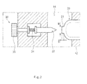
- FIG. 2 is a partially enlarged view of a punching unit included in the battery pack in FIG. 1
- FIG.3 illustrates a situation where a pin member included in the punching unit in FIG.2 approaches towards a pouch type battery cell.
- FIGS. 1 to 3 illustrate only partial configurations as cross sections to easily understand components.
- a battery pack 100 includes a plurality of pouch type battery cells 20, a case 10 holding the plurality of pouch type battery cells 20, and a punching unit 30 having pin members 32 of which number is equal to that of the pouch type battery cells 20.
- the pouch type battery cells 20 hold an electrode assembly therein, which has a cathode plate, an anode plate, and a separator, and electrode leads are connected to electrode taps extending from each of the cathode and anode plates. It is noted that the above structure is a typical structure of the pouch type battery cells 20, and thus is not specifically illustrated in drawings.
- the electrode assembly is held in an area indicated by a dotted line of the pouch type battery cells in FIGS. 2 and 3 .
- the case 10 includes partitions 12 suppressing the pouch type battery cells 20 from expanding in a thickness direction thereof, and the pouch type battery cells 20 are respectively held in spaces defined by the partitions 12.
- Each of the pouch type battery cells 20 is disposed between two partitions 12 or between the partition 12 and an inner side of the case 10. In addition, either side of the pouch type battery cell 20 is in contact with the partition 12 or the inner side of the case 10.
- both ends of the pouch type battery cell 20 is expanded when viewed from FIG. 1 .
- the both ends of the pouch type battery cell 20 may expand in a thickness direction as well as a width direction.
- suppressing the pouch type battery cell 20 from expanding in the thickness direction thereof by the partition 12 does not means suppressing the entire region of the pouch type battery cell 20 from expanding in the thickness direction thereof; but rather means suppressing the pouch type battery cell 20 from expanding in the thickness direction thereof in a region where the pouch type battery cell 20 is in contact with the partition 12.
- the case 10 has spaces 14 and 15 to allow the pouch type battery cells 20 to expand in the width direction thereof.
- the pin member 32 of the punching unit 30 is installed on the case 10 to pierce a portion of surfaces of the pouch type battery cells 20, which is not supported by the partition 12. Also, the pin member 32 may be installed on the case 10 to adjust a distance from the surface of the pouch type battery cell 20.
- a position of the pin member 32 may be adjusted by using an adjusting lever 36 and a screw thread 34.
- FIGS. 2 and 3 illustrate that the adjusting lever 36 is rotatably installed on the case 10, the screw thread 34 is formed on an end portion of the adjusting lever 36, a bore is formed at the center of the pin member 32, a female screw is formed in the bore, and the screw thread 34 is inserted into the female screw.
- the pin member 32 may have a key on a surface thereof such that the pin member 32 only linearly moves toward or away from the pouch type battery cell 20 without rotating with reference to the case 10, and the case 10 may have a key groove at a position corresponding to the key.
- the pin member 32 may be designed to have a polygonal section such as rectangular and hexagonal sections, thereby preventing rotation of the pin member 32.
- the screw thread 34 rotates and the pin member 32 does not rotate.
- the female screw formed on the bore of the pin member 32 moves relative TO the screw thread 34 to allow the pin member 32 to linearly move toward or away from the pouch type battery cells 20.
- the adjusting lever 36 is configured to adjust the position of the pin member 32 and installed on each of the pin members 32, and therefore, the number of pin members 32 is equal to the number of the adjusting levers 36.
- the pouch type battery cell 20 may have a protruding part 22 formed at the surface thereof to protrude toward a region where the pin member 32 is installed.
- a width W and depth D of the protruding part 22 may be variously designed.
- the protruding part 22 is designed to have great width W and depth D, it is advantageous in that the pouch type battery cell 20 is not easily punched although the pouch type battery cell 20 is brought into contact with the pin member 32 due to careless handling.
- the position of the pin member 32 may be adjusted from a configuration in FIG. 2 to a configuration in FIG. 3 and vice versa. Furthermore, the distance between the pin member 32 and the pouch type battery cell 20 may be further increased by use of the adjusting lever 36 compared with the distance illustrated in FIG. 2 .
- the pouch type battery cell 20 in FIG. 2 is pierced by the pin member 32 to discharge gases inside the pouch type battery cell 20, only if the pouch type battery cell 20 considerably expands.
- the pouch type battery cell 20 in FIG. 3 is pierced by the pin member 32 to discharge gases inside the pouch type battery cell 20, even if the pouch type battery cell 20 slightly expands.
- the pin member 32 When a reference pressure for discharging internal gases of the pouch type battery cell 20 to the outside is high, the pin member 32 may be adjusted to approach toward the pouch type battery cell 20 as illustrated in FIG. 3 by using the adjusting lever 36. On the contrary, when a reference pressure for discharging inner gases of the pouch type battery cell 20 to the outside is low, the pin member 32 may be adjusted to move far away from the pouch type battery cell 20 as illustrated in FIG. 2 by using the adjusting lever 36.
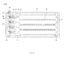
- FIG. 4 is a longitudinal sectional view of a battery pack according to a second embodiment of the present invention.
- a battery pack 100A according to the second embodiment of the present invention has a different configuration of a punching unit 30.
- structures of a pin member 32 and a screw thread 34 of the punching unit 30 in the second embodiment are same as those in the first embodiment.
- a first gear 38 instead of an adjusting lever 36 is placed at a position corresponding to the adjusting lever 36 in the first embodiment.
- the first gear 38 is interlocked with each of pin members 32 to convert a rotational movement to a linear movement in a longitudinal direction of the pin member 32, and engaged with a second gear 48 which will be described later.
- a plurality of second gears 48 are provided, of which number is equal to number of the first gears 38, and the plurality of second gears 48 are disposed along a plurality of thin and long adjusting shafts 42.
- Bearings 43 and 44 may be installed on a case 10 for smooth rotation of the adjusting shaft 42.
- first gear 38 and the second gear 48 are illustrated as a bevel gear, the first and second gears 38 and 48 are not limited to the bevel gear only, and thus various configurations having the same function as the bevel gear may be used.
- each of the pin members 32 may be simultaneously adjusted by using one adjusting lever 46.
- the pin member 32 may be adjusted by moving toward or away from the pouch type battery cell 20.
- the battery pack of the modified embodiment can be applied to gas discharge various reference pressures without changing a structure of the pouch type battery cell 20 as illustrated in the first and the second embodiments.
Landscapes
- Chemical & Material Sciences (AREA)
- Chemical Kinetics & Catalysis (AREA)
- Electrochemistry (AREA)
- General Chemical & Material Sciences (AREA)
- Engineering & Computer Science (AREA)
- Manufacturing & Machinery (AREA)
- Battery Mounting, Suspending (AREA)
- Sealing Battery Cases Or Jackets (AREA)
- Gas Exhaust Devices For Batteries (AREA)
Abstract
Description
- The present invention relates to a battery pack capable of discharging gases in a pouch type battery cell, and more particularly, to a battery pack capable of discharging gases in a pouch type battery cell when a gas pressure inside the pouch type battery cell is increased over a reference pressure to expand the pouch type battery cell.
- In general, in line with technological development and increasing demands for mobile devices, demands for secondary batteries are also increasing sharply, and, most of all, lithium (ion/polymer) secondary batteries having a high energy density, a high operation voltage, and excellent storage and life characteristics are widely used as an energy source for various electronic products as well as mobile devices.
- Korea Patent Publication No.
2009-0065587 - Meanwhile, a reference pressure at which gases inside the pouch type secondary battery are discharged may be varied according to specifications and operation conditions of electronic/mechanical devices on which the pouch type secondary battery is installed. That is, some electronic/mechanical devices need to discharge gases even if an internal gas pressure of the pouch type secondary battery is slightly increased, whereas other electronic/mechanical devices do not need to discharge gases even when the internal gas pressure of the pouch type secondary battery is significantly increased.
- However, the disclosed patent is disadvantageous in that, when a gas discharge reference pressure of the pouch type secondary battery required by the respective electronic/mechanical devices is varied, a design for the sealing part should be changed.
- It is assumed that a pouch type secondary battery is manufactured according to a gas discharge reference pressure required by a specific electronic/mechanical device and installed on the electronic/mechanical device. However, when the preset gas discharge reference pressure is considered inappropriate for the electronic/mechanical device during operation and thus the gas discharge reference pressure needs to be increased or decreased, there is a limitation in that the existing pouch type secondary battery should be entirely replaced by a pouch type secondary battery having a newly changed gas discharge reference pressure.
- To solve the above-described limitations, an aspect of the present invention provides a battery pack which does not need to change a design of a pouch type battery cell according to a gas discharge reference pressure.
- Another aspect of the present invention provides a battery pack, capable of simply changing a gas discharge reference pressure of a pouch type battery cell included in the battery pack which is already installed on an electronic/mechanical device.
- According to an aspect of the present invention, there is provided a battery pack according to a preferred embodiment includes: a plurality of pouch type battery cells; a case comprising partitions suppressing the pouch type battery cells from expanding in a thickness direction thereof, wherein the pouch type battery cells are respectively held in spaces defined by the partitions; and a punching unit installed on the case to pierce a portion of surfaces of the pouch type battery cells , which is not supported by the partition, and having pin members of which number is equal to that of the pouch type battery cells.
- The pouch type batter cell may include a protruding part at a surface thereof to protrude toward a region where the pin member is installed.
- The case may have a space which allows the plurality of pouch type battery cells to expand in a width direction thereof.
- The pin members may be installed on the case so that a distance between the pin member and a surface of the pouch type battery cell is adjustable.
- The battery pack may include an adjusting lever configured to adjust a position of each of the pin members.
- The battery pack may include an adjusting lever configured to simultaneously adjust positions of the pin members.
- The battery pack may further include: a first gear interlocked with each of the pin members to convert a rotational movement to a linear movement in a longitudinal direction of the pin member; and an adjusting shaft having a plurality of second gears engaged with a plurality of first gears, and rotating along with rotation of the adjusting lever.
- According to the present invention, it is possible to provide a battery pack which does not need to change a design of a pouch type battery cell according to a gas discharge reference pressure.
- In addition, it is possible to provide a battery pack capable of simply changing a gas discharge reference pressure of a pouch type battery cell included in the battery pack which is already installed on an electronic/mechanical device.
- The above and other aspects, features and other advantages of the present invention will be more clearly understood from the following detailed description taken in conjunction with the accompanying drawings, in which:
-
FIG. 1 is a longitudinal sectional view of a battery pack according to a first embodiment of the present invention; -
FIG. 2 is a partially enlarged view of a punching unit included in the battery pack inFIG. 1 ; -
FIG.3 illustrates a situation where a pin member included in the punching unit inFIG.2 approaches towards a pouch type battery cell; and -
FIG. 4 is a longitudinal sectional view of a battery pack according to a second embodiment of the present invention. - Exemplary embodiments of the present invention will now be described in detail with reference to the accompanying drawings.
- Terms or words used in this specification and claims should not be restrictively interpreted as ordinary meanings or dictionary-based meanings, but should be interpreted as meanings and concepts conforming to the scope of the present invention on the basis of the principle that an inventor can properly define the concept of a term to describe and explain his or her invention in the best ways.. Accordingly, it should be considered that embodiments set forth herein and configurations illustrated in drawings are merely preferred embodiments of the invention and do not represent the technical spirit of the present invention. Therefore, it will be understood that, at the time of filing of the present application, they can be replaced with a variety of these equivalents and modifications.
- Each component in the drawing or the size of the components that make up a specific part may be exaggerated, omitted or schematically illustrated for clarity and convenience of description. Thus, the size of each component does not utterly reflect an actual size. In the following description of the present invention, a detailed description of known functions or configurations incorporated herein will be omitted to avoid making the subject matter of the present invention unclear.
-
FIG. 1 is a longitudinal sectional view of a battery pack according to a first embodiment of the present invention,FIG. 2 is a partially enlarged view of a punching unit included in the battery pack inFIG. 1 , andFIG.3 illustrates a situation where a pin member included in the punching unit inFIG.2 approaches towards a pouch type battery cell. - It should be noted that
FIGS. 1 to 3 illustrate only partial configurations as cross sections to easily understand components. - Referring to
FIGS. 1 to 3 , abattery pack 100 according to a first embodiment of the present invention includes a plurality of pouchtype battery cells 20, acase 10 holding the plurality of pouchtype battery cells 20, and apunching unit 30 havingpin members 32 of which number is equal to that of the pouchtype battery cells 20. - The pouch
type battery cells 20 hold an electrode assembly therein, which has a cathode plate, an anode plate, and a separator, and electrode leads are connected to electrode taps extending from each of the cathode and anode plates. It is noted that the above structure is a typical structure of the pouchtype battery cells 20, and thus is not specifically illustrated in drawings. The electrode assembly is held in an area indicated by a dotted line of the pouch type battery cells inFIGS. 2 and3 . - The
case 10 includespartitions 12 suppressing the pouchtype battery cells 20 from expanding in a thickness direction thereof, and the pouchtype battery cells 20 are respectively held in spaces defined by thepartitions 12. - Each of the pouch
type battery cells 20 is disposed between twopartitions 12 or between thepartition 12 and an inner side of thecase 10. In addition, either side of the pouchtype battery cell 20 is in contact with thepartition 12 or the inner side of thecase 10. - When gas is excessively generated in the pouch
type battery cell 20 to increase pressure due to overcharging, internal short, and the like, the pouchtype battery cell 20 is expanded. Since the pouchtype battery cell 20 is suppressed from expanding in the thickness direction thereof by means of thepartition 12 or the inner side of thecase 10, both ends of the pouchtype battery cell 20 is expanded when viewed fromFIG. 1 . Of course, the both ends of the pouchtype battery cell 20 may expand in a thickness direction as well as a width direction. - Accordingly, suppressing the pouch
type battery cell 20 from expanding in the thickness direction thereof by thepartition 12 does not means suppressing the entire region of the pouchtype battery cell 20 from expanding in the thickness direction thereof; but rather means suppressing the pouchtype battery cell 20 from expanding in the thickness direction thereof in a region where the pouchtype battery cell 20 is in contact with thepartition 12. - Meanwhile, the
case 10 hasspaces type battery cells 20 to expand in the width direction thereof. - The
pin member 32 of thepunching unit 30 is installed on thecase 10 to pierce a portion of surfaces of the pouchtype battery cells 20, which is not supported by thepartition 12. Also, thepin member 32 may be installed on thecase 10 to adjust a distance from the surface of the pouchtype battery cell 20. - For example, a position of the
pin member 32 may be adjusted by using an adjustinglever 36 and ascrew thread 34.FIGS. 2 and3 illustrate that the adjustinglever 36 is rotatably installed on thecase 10, thescrew thread 34 is formed on an end portion of the adjustinglever 36, a bore is formed at the center of thepin member 32, a female screw is formed in the bore, and thescrew thread 34 is inserted into the female screw. - The
pin member 32 may have a key on a surface thereof such that thepin member 32 only linearly moves toward or away from the pouchtype battery cell 20 without rotating with reference to thecase 10, and thecase 10 may have a key groove at a position corresponding to the key. Alternatively, thepin member 32 may be designed to have a polygonal section such as rectangular and hexagonal sections, thereby preventing rotation of thepin member 32. - When the adjusting
lever 36 is rotated, thescrew thread 34 rotates and thepin member 32 does not rotate. Thus, the female screw formed on the bore of thepin member 32 moves relative TO thescrew thread 34 to allow thepin member 32 to linearly move toward or away from the pouchtype battery cells 20. - The adjusting
lever 36 is configured to adjust the position of thepin member 32 and installed on each of thepin members 32, and therefore, the number ofpin members 32 is equal to the number of the adjustinglevers 36. - The pouch
type battery cell 20 may have aprotruding part 22 formed at the surface thereof to protrude toward a region where thepin member 32 is installed. A width W and depth D of the protrudingpart 22 may be variously designed. When the protrudingpart 22 is designed to have great width W and depth D, it is advantageous in that the pouchtype battery cell 20 is not easily punched although the pouchtype battery cell 20 is brought into contact with thepin member 32 due to careless handling. - The position of the
pin member 32 may be adjusted from a configuration inFIG. 2 to a configuration inFIG. 3 and vice versa. Furthermore, the distance between thepin member 32 and the pouchtype battery cell 20 may be further increased by use of the adjustinglever 36 compared with the distance illustrated inFIG. 2 . - In comparison with the configuration in
FIG. 3 , the pouchtype battery cell 20 inFIG. 2 is pierced by thepin member 32 to discharge gases inside the pouchtype battery cell 20, only if the pouchtype battery cell 20 considerably expands. On the contrary, in comparison with the configuration inFIG. 2 , the pouchtype battery cell 20 inFIG. 3 is pierced by thepin member 32 to discharge gases inside the pouchtype battery cell 20, even if the pouchtype battery cell 20 slightly expands. - When a reference pressure for discharging internal gases of the pouch
type battery cell 20 to the outside is high, thepin member 32 may be adjusted to approach toward the pouchtype battery cell 20 as illustrated inFIG. 3 by using the adjustinglever 36. On the contrary, when a reference pressure for discharging inner gases of the pouchtype battery cell 20 to the outside is low, thepin member 32 may be adjusted to move far away from the pouchtype battery cell 20 as illustrated inFIG. 2 by using the adjustinglever 36. - In other word, it is possible to meet various gas discharge standards of the pouch
type battery cell 20 by only adjusting the position of thepin member 32, without changing a design of the pouch type battery cell itself each time. - Furthermore, in the case where a pouch
type battery cell 20 included in thebattery pack 100 which has been already installed on electronic/mechanical devices needs to change a gas discharge reference pressure, it is advantageous in that such a change may be achieved by only adjusting the adjustinglever 36, without replacing thebattery pack 100 itself. -
FIG. 4 is a longitudinal sectional view of a battery pack according to a second embodiment of the present invention. - Contents common to the first embodiment will be omitted to avoid duplicate explanation and a description will be focused on contents different from those of the first embodiment.
- A
battery pack 100A according to the second embodiment of the present invention has a different configuration of apunching unit 30. - Referring to
FIG. 4 , structures of apin member 32 and ascrew thread 34 of the punchingunit 30 in the second embodiment are same as those in the first embodiment. However, a first gear 38 instead of an adjustinglever 36 is placed at a position corresponding to the adjustinglever 36 in the first embodiment. - The first gear 38 is interlocked with each of
pin members 32 to convert a rotational movement to a linear movement in a longitudinal direction of thepin member 32, and engaged with asecond gear 48 which will be described later. - A plurality of
second gears 48 are provided, of which number is equal to number of the first gears 38, and the plurality ofsecond gears 48 are disposed along a plurality of thin and long adjustingshafts 42.Bearings case 10 for smooth rotation of the adjustingshaft 42. - An adjusting
lever 46 of which a position is relatively fixed to the adjustingshaft 42 is formed on an end portion of the adjustingshaft 42. Although the first gear 38 and thesecond gear 48 are illustrated as a bevel gear, the first andsecond gears 38 and 48 are not limited to the bevel gear only, and thus various configurations having the same function as the bevel gear may be used. - When the adjusting
lever 46 rotates, the adjustingshaft 42 rotates along with the adjustinglever 46. Then, the plurality ofsecond gears 48 fixed to the adjustingshaft 42 rotate, and the first gears 38 also rotate because the first gears 38 and the second gears are engaged with each other. - When the first gear 38 rotates, the
screw thread 34 rotates and thepin member 32 does not rotate. Thus, a female screw formed on a bore of thepin member 32 moves relative to thescrew thread 34, so that thepin member 32 linearly moves toward or away from the pouchtype battery cell 20. - In the second embodiment, each of the
pin members 32 may be simultaneously adjusted by using one adjustinglever 46. - In the first and the second embodiments, the
pin member 32 may be adjusted by moving toward or away from the pouchtype battery cell 20. - However, a modified embodiment may be presumed in which components of the punching
unit 30 other than thepin members 32 are excluded. - In this modified embodiment, while having
pin members 32 with various lengths, a relativelyshorter pin member 32 is installed in thecase 10 when the gas discharge reference pressure of the pouchtype batter cell 20 is high; and a relativelylong pin member 32 is installed in thecase 10 when the reference pressure of discharging gas of the pouchtype batter cell 20 is low. Thus, the battery pack of the modified embodiment can be applied to gas discharge various reference pressures without changing a structure of the pouchtype battery cell 20 as illustrated in the first and the second embodiments. - While the present invention has been shown and described in connection with the exemplary embodiments, it will be apparent to those skilled in the art that modifications and variations can be made without departing from the spirit and scope of the invention as defined by the appended claims.
- This application claims the priority of Korean Patent Application No.
10-2013-0049351 filed on May 02, 2013
Claims (7)
- A battery pack, comprising:a plurality of pouch type battery cells;a case comprising partitions suppressing the pouch type battery cells from expanding in a thickness direction thereof, wherein the pouch type battery cells are respectively held in spaces defined by the partitions; anda punching unit installed on the case to pierce a portion of surfaces of the pouch type battery cells, which is not supported by the partition, and having pin members of which number is equal to that of the pouch type battery cells.
- The battery pack of claim 1, wherein the pouch type batter cell comprises a protruding part at a surface thereof to protrude toward a region where the pin member is installed.
- The battery pack of claim 1, wherein the case has a space which allows the plurality of pouch type battery cells to expand in a width direction thereof.
- The battery pack of claim 1, wherein the pin members are installed on the case so that a distance between the pin member and a surface of the pouch type battery cell is adjustable.
- The battery pack of claim 4, wherein the battery pack comprises an adjusting lever configured to adjust a position of each of the pin members.
- The battery pack of claim 4, wherein the battery pack comprises an adjusting lever configured to simultaneously adjust positions of the pin members.
- The battery pack of claim 6, further comprising:a first gear interlocked with each of the pin members to convert a rotational movement to a linear movement in a longitudinal direction of the pin member; andan adjusting shaft having a plurality of second gears engaged with a plurality of first gears, and rotating along with rotation of the adjusting lever.
Applications Claiming Priority (2)
| Application Number | Priority Date | Filing Date | Title |
|---|---|---|---|
| KR1020130049351A KR101605936B1 (en) | 2013-05-02 | 2013-05-02 | Battery pack capable of releasing gas inside of pouch type battery cell |
| PCT/KR2014/003689 WO2014178579A1 (en) | 2013-05-02 | 2014-04-25 | Battery pack having pouch-type battery cells from which gas therein can be released |
Publications (3)
| Publication Number | Publication Date |
|---|---|
| EP2879204A1 true EP2879204A1 (en) | 2015-06-03 |
| EP2879204A4 EP2879204A4 (en) | 2015-08-26 |
| EP2879204B1 EP2879204B1 (en) | 2016-06-08 |
Family
ID=51563345
Family Applications (1)
| Application Number | Title | Priority Date | Filing Date |
|---|---|---|---|
| EP14791384.2A Active EP2879204B1 (en) | 2013-05-02 | 2014-04-25 | Battery pack having pouch-type battery cells from which gas therein can be released |
Country Status (6)
| Country | Link |
|---|---|
| US (1) | US9806311B2 (en) |
| EP (1) | EP2879204B1 (en) |
| JP (1) | JP5946588B2 (en) |
| KR (1) | KR101605936B1 (en) |
| CN (2) | CN203850367U (en) |
| WO (1) | WO2014178579A1 (en) |
Cited By (2)
| Publication number | Priority date | Publication date | Assignee | Title |
|---|---|---|---|---|
| CN108023033A (en) * | 2016-11-01 | 2018-05-11 | 福特全球技术公司 | Battery enclosure gas deflation assembly and method for exhausting |
| WO2024240344A1 (en) * | 2023-05-24 | 2024-11-28 | Abb Schweiz Ag | Electrochemical device provided with a safety arrangement for a pouch cell |
Families Citing this family (17)
| Publication number | Priority date | Publication date | Assignee | Title |
|---|---|---|---|---|
| KR101605936B1 (en) * | 2013-05-02 | 2016-03-23 | 주식회사 엘지화학 | Battery pack capable of releasing gas inside of pouch type battery cell |
| JP6667109B2 (en) | 2016-11-11 | 2020-03-18 | トヨタ自動車株式会社 | Battery parts assembly equipment |
| KR102106111B1 (en) * | 2016-12-20 | 2020-04-29 | 주식회사 엘지화학 | Method for injecting electrolyte of pouch type battery |
| KR102178786B1 (en) * | 2017-03-03 | 2020-11-13 | 주식회사 엘지화학 | Catridge and battery module including the same |
| KR102144922B1 (en) * | 2017-05-08 | 2020-08-14 | 주식회사 엘지화학 | Battery explosion prevention device, battery pack and operation method |
| KR102365631B1 (en) | 2018-01-09 | 2022-02-21 | 주식회사 엘지에너지솔루션 | Battery module |
| KR102384308B1 (en) * | 2018-12-07 | 2022-04-07 | 주식회사 엘지에너지솔루션 | Pouch-type Battery Cell Having Venting Member and Battery Pack Comprising the Same |
| KR102389408B1 (en) | 2019-01-07 | 2022-04-22 | 주식회사 엘지에너지솔루션 | Degasing device, producing facility and producing method of secondary battery comprising the same |
| KR102772424B1 (en) * | 2019-08-05 | 2025-02-25 | 주식회사 엘지에너지솔루션 | Degassing apparatus for secondary battery and degassing method for secondary battery using the same |
| KR102295232B1 (en) * | 2019-09-03 | 2021-08-31 | 파이어킴 주식회사 | Capsule type fire extinguisher for preventing battery explosion and battery having the fire extinguisher |
| KR20210099469A (en) | 2020-02-04 | 2021-08-12 | 엘지전자 주식회사 | Battery cell |
| KR102924578B1 (en) | 2020-02-26 | 2026-02-05 | 엘지전자 주식회사 | Battery pack |
| TWI890834B (en) * | 2020-08-04 | 2025-07-21 | 南韓商Lg新能源股份有限公司 | Battery module, battery pack comprising the same, and vehicle |
| JP7585943B2 (en) * | 2021-03-31 | 2024-11-19 | トヨタ自動車株式会社 | Power storage device |
| CN116345055B (en) * | 2023-04-08 | 2024-02-09 | 金派克新能源科技(淮北)有限公司 | Electric control pressure regulating device for new energy automobile battery pack |
| KR102613036B1 (en) | 2023-07-20 | 2023-12-12 | (주)연호상사 | Battery module |
| CN118281453B (en) * | 2024-04-01 | 2024-12-03 | 湖北美赛尔科技有限公司 | A lithium battery pack protection structure and a lithium battery pack |
Family Cites Families (11)
| Publication number | Priority date | Publication date | Assignee | Title |
|---|---|---|---|---|
| US2492256A (en) * | 1947-06-06 | 1949-12-27 | Charles A Bailiff | Battery terminal |
| JP2007141778A (en) * | 2005-11-22 | 2007-06-07 | Toyota Motor Corp | Batteries and batteries |
| KR100959090B1 (en) * | 2007-12-18 | 2010-05-20 | 주식회사 엘지화학 | Pouch type secondary battery with improved safety |
| JP2010186786A (en) * | 2009-02-10 | 2010-08-26 | Fdk Corp | Electrical storage device and electrical storage device module |
| KR101393167B1 (en) * | 2009-05-20 | 2014-05-08 | 존슨 컨트롤즈 테크놀로지, 엘엘씨 | Lithium ion battery module |
| KR101093937B1 (en) | 2009-11-26 | 2011-12-13 | 삼성에스디아이 주식회사 | Secondary Battery and Battery Pack Using the Same |
| KR101097101B1 (en) * | 2009-12-29 | 2011-12-22 | 주식회사 루트제이드 | Secondary battery having exploding prevention device |
| KR101182275B1 (en) * | 2010-11-02 | 2012-09-12 | 삼성에스디아이 주식회사 | Rechargeable battery |
| KR20120136750A (en) * | 2011-06-10 | 2012-12-20 | 에스케이이노베이션 주식회사 | Battery having venting structure |
| KR20130000014A (en) * | 2011-06-22 | 2013-01-02 | 에스케이이노베이션 주식회사 | Pouch type secondary battery |
| KR101605936B1 (en) * | 2013-05-02 | 2016-03-23 | 주식회사 엘지화학 | Battery pack capable of releasing gas inside of pouch type battery cell |
-
2013
- 2013-05-02 KR KR1020130049351A patent/KR101605936B1/en active Active
-
2014
- 2014-04-25 JP JP2015523040A patent/JP5946588B2/en active Active
- 2014-04-25 WO PCT/KR2014/003689 patent/WO2014178579A1/en not_active Ceased
- 2014-04-25 EP EP14791384.2A patent/EP2879204B1/en active Active
- 2014-05-05 CN CN201420226285.6U patent/CN203850367U/en not_active Expired - Lifetime
- 2014-05-05 CN CN201410187514.2A patent/CN104134771B/en active Active
- 2014-12-01 US US14/556,680 patent/US9806311B2/en active Active
Cited By (3)
| Publication number | Priority date | Publication date | Assignee | Title |
|---|---|---|---|---|
| CN108023033A (en) * | 2016-11-01 | 2018-05-11 | 福特全球技术公司 | Battery enclosure gas deflation assembly and method for exhausting |
| CN108023033B (en) * | 2016-11-01 | 2022-04-26 | 福特全球技术公司 | Battery enclosure vent assembly and venting method |
| WO2024240344A1 (en) * | 2023-05-24 | 2024-11-28 | Abb Schweiz Ag | Electrochemical device provided with a safety arrangement for a pouch cell |
Also Published As
| Publication number | Publication date |
|---|---|
| JP2015526851A (en) | 2015-09-10 |
| CN104134771B (en) | 2016-07-06 |
| KR101605936B1 (en) | 2016-03-23 |
| WO2014178579A1 (en) | 2014-11-06 |
| JP5946588B2 (en) | 2016-07-06 |
| CN203850367U (en) | 2014-09-24 |
| EP2879204B1 (en) | 2016-06-08 |
| US20150086817A1 (en) | 2015-03-26 |
| EP2879204A4 (en) | 2015-08-26 |
| CN104134771A (en) | 2014-11-05 |
| KR20140130859A (en) | 2014-11-12 |
| US9806311B2 (en) | 2017-10-31 |
Similar Documents
| Publication | Publication Date | Title |
|---|---|---|
| US9806311B2 (en) | Battery pack capable of discharging gases in pouch type battery cell | |
| US11935997B2 (en) | Pouch exterior for secondary battery, pouch-type secondary battery using the pouch exterior, and method of manufacturing the pouch-type secondary battery | |
| US8153289B2 (en) | Secondary battery | |
| US8404386B2 (en) | Method of manufacturing lithium secondary battery and lithium secondary battery | |
| JP5120638B2 (en) | Battery with current interruption mechanism | |
| EP3082176A1 (en) | Secondary battery pack with variable compression | |
| EP2958168B1 (en) | Battery module | |
| EP3699975A1 (en) | Pouch-type secondary battery having electrolyte supplement groove | |
| KR20100039853A (en) | Cid retention device for li-ion cell | |
| CN102017224A (en) | Prismatic storage battery or cell with flexible recessed portion | |
| EP3739666B1 (en) | Pouch-type battery cell comprising venting member and battery pack comprising the same | |
| EP4068444A1 (en) | Apparatus for manufacturing secondary battery and method for manufacturing secondary battery | |
| US11114729B2 (en) | Energy storage device and method of manufacturing energy storage device | |
| CN113228389A (en) | Battery pack and battery system | |
| EP4068461B1 (en) | Pouch-shaped battery cell configured such that replenishment of electrolytic solution is possible | |
| JP2016126975A (en) | Cylindrical battery | |
| KR20160032888A (en) | Battery cell and method for manufacturing the same | |
| US10910663B2 (en) | Secondary battery | |
| US20150214512A1 (en) | Battery cell | |
| US20190019999A1 (en) | Energy storage device | |
| US11127981B2 (en) | Battery cell including battery case having protrusion corresponding to stepped electrode assembly | |
| EP3522262B1 (en) | Battery cell having overcharge prevention member | |
| JP6156109B2 (en) | Temporary sealing plug for power storage device | |
| US20260081203A1 (en) | Die apparatus for manufacturing secondary battery and link-type knockout unit for die apparatus | |
| US20200321588A1 (en) | Stacked secondary battery and bag-like separator |
Legal Events
| Date | Code | Title | Description |
|---|---|---|---|
| PUAI | Public reference made under article 153(3) epc to a published international application that has entered the european phase |
Free format text: ORIGINAL CODE: 0009012 |
|
| 17P | Request for examination filed |
Effective date: 20150225 |
|
| AK | Designated contracting states |
Kind code of ref document: A1 Designated state(s): AL AT BE BG CH CY CZ DE DK EE ES FI FR GB GR HR HU IE IS IT LI LT LU LV MC MK MT NL NO PL PT RO RS SE SI SK SM TR |
|
| AX | Request for extension of the european patent |
Extension state: BA ME |
|
| REG | Reference to a national code |
Ref country code: DE Ref legal event code: R079 Ref document number: 602014002271 Country of ref document: DE Free format text: PREVIOUS MAIN CLASS: H01M0002120000 Ipc: H01M0002020000 |
|
| RA4 | Supplementary search report drawn up and despatched (corrected) |
Effective date: 20150723 |
|
| RIC1 | Information provided on ipc code assigned before grant |
Ipc: H01M 2/02 20060101AFI20150717BHEP Ipc: H01M 2/10 20060101ALI20150717BHEP Ipc: H01M 2/12 20060101ALI20150717BHEP |
|
| GRAJ | Information related to disapproval of communication of intention to grant by the applicant or resumption of examination proceedings by the epo deleted |
Free format text: ORIGINAL CODE: EPIDOSDIGR1 |
|
| GRAP | Despatch of communication of intention to grant a patent |
Free format text: ORIGINAL CODE: EPIDOSNIGR1 |
|
| GRAS | Grant fee paid |
Free format text: ORIGINAL CODE: EPIDOSNIGR3 |
|
| DAX | Request for extension of the european patent (deleted) | ||
| INTG | Intention to grant announced |
Effective date: 20160406 |
|
| GRAA | (expected) grant |
Free format text: ORIGINAL CODE: 0009210 |
|
| AK | Designated contracting states |
Kind code of ref document: B1 Designated state(s): AL AT BE BG CH CY CZ DE DK EE ES FI FR GB GR HR HU IE IS IT LI LT LU LV MC MK MT NL NO PL PT RO RS SE SI SK SM TR |
|
| REG | Reference to a national code |
Ref country code: GB Ref legal event code: FG4D |
|
| REG | Reference to a national code |
Ref country code: CH Ref legal event code: EP |
|
| REG | Reference to a national code |
Ref country code: IE Ref legal event code: FG4D |
|
| REG | Reference to a national code |
Ref country code: DE Ref legal event code: R096 Ref document number: 602014002271 Country of ref document: DE |
|
| REG | Reference to a national code |
Ref country code: AT Ref legal event code: REF Ref document number: 805784 Country of ref document: AT Kind code of ref document: T Effective date: 20160715 |
|
| REG | Reference to a national code |
Ref country code: LT Ref legal event code: MG4D |
|
| REG | Reference to a national code |
Ref country code: NL Ref legal event code: MP Effective date: 20160608 |
|
| PG25 | Lapsed in a contracting state [announced via postgrant information from national office to epo] |
Ref country code: FI Free format text: LAPSE BECAUSE OF FAILURE TO SUBMIT A TRANSLATION OF THE DESCRIPTION OR TO PAY THE FEE WITHIN THE PRESCRIBED TIME-LIMIT Effective date: 20160608 Ref country code: NO Free format text: LAPSE BECAUSE OF FAILURE TO SUBMIT A TRANSLATION OF THE DESCRIPTION OR TO PAY THE FEE WITHIN THE PRESCRIBED TIME-LIMIT Effective date: 20160908 Ref country code: LT Free format text: LAPSE BECAUSE OF FAILURE TO SUBMIT A TRANSLATION OF THE DESCRIPTION OR TO PAY THE FEE WITHIN THE PRESCRIBED TIME-LIMIT Effective date: 20160608 |
|
| REG | Reference to a national code |
Ref country code: AT Ref legal event code: MK05 Ref document number: 805784 Country of ref document: AT Kind code of ref document: T Effective date: 20160608 |
|
| PG25 | Lapsed in a contracting state [announced via postgrant information from national office to epo] |
Ref country code: SE Free format text: LAPSE BECAUSE OF FAILURE TO SUBMIT A TRANSLATION OF THE DESCRIPTION OR TO PAY THE FEE WITHIN THE PRESCRIBED TIME-LIMIT Effective date: 20160608 Ref country code: GR Free format text: LAPSE BECAUSE OF FAILURE TO SUBMIT A TRANSLATION OF THE DESCRIPTION OR TO PAY THE FEE WITHIN THE PRESCRIBED TIME-LIMIT Effective date: 20160909 Ref country code: LV Free format text: LAPSE BECAUSE OF FAILURE TO SUBMIT A TRANSLATION OF THE DESCRIPTION OR TO PAY THE FEE WITHIN THE PRESCRIBED TIME-LIMIT Effective date: 20160608 Ref country code: RS Free format text: LAPSE BECAUSE OF FAILURE TO SUBMIT A TRANSLATION OF THE DESCRIPTION OR TO PAY THE FEE WITHIN THE PRESCRIBED TIME-LIMIT Effective date: 20160608 Ref country code: NL Free format text: LAPSE BECAUSE OF FAILURE TO SUBMIT A TRANSLATION OF THE DESCRIPTION OR TO PAY THE FEE WITHIN THE PRESCRIBED TIME-LIMIT Effective date: 20160608 Ref country code: HR Free format text: LAPSE BECAUSE OF FAILURE TO SUBMIT A TRANSLATION OF THE DESCRIPTION OR TO PAY THE FEE WITHIN THE PRESCRIBED TIME-LIMIT Effective date: 20160608 Ref country code: ES Free format text: LAPSE BECAUSE OF FAILURE TO SUBMIT A TRANSLATION OF THE DESCRIPTION OR TO PAY THE FEE WITHIN THE PRESCRIBED TIME-LIMIT Effective date: 20160608 |
|
| PG25 | Lapsed in a contracting state [announced via postgrant information from national office to epo] |
Ref country code: RO Free format text: LAPSE BECAUSE OF FAILURE TO SUBMIT A TRANSLATION OF THE DESCRIPTION OR TO PAY THE FEE WITHIN THE PRESCRIBED TIME-LIMIT Effective date: 20160608 Ref country code: IT Free format text: LAPSE BECAUSE OF FAILURE TO SUBMIT A TRANSLATION OF THE DESCRIPTION OR TO PAY THE FEE WITHIN THE PRESCRIBED TIME-LIMIT Effective date: 20160608 Ref country code: SK Free format text: LAPSE BECAUSE OF FAILURE TO SUBMIT A TRANSLATION OF THE DESCRIPTION OR TO PAY THE FEE WITHIN THE PRESCRIBED TIME-LIMIT Effective date: 20160608 Ref country code: CZ Free format text: LAPSE BECAUSE OF FAILURE TO SUBMIT A TRANSLATION OF THE DESCRIPTION OR TO PAY THE FEE WITHIN THE PRESCRIBED TIME-LIMIT Effective date: 20160608 Ref country code: EE Free format text: LAPSE BECAUSE OF FAILURE TO SUBMIT A TRANSLATION OF THE DESCRIPTION OR TO PAY THE FEE WITHIN THE PRESCRIBED TIME-LIMIT Effective date: 20160608 Ref country code: IS Free format text: LAPSE BECAUSE OF FAILURE TO SUBMIT A TRANSLATION OF THE DESCRIPTION OR TO PAY THE FEE WITHIN THE PRESCRIBED TIME-LIMIT Effective date: 20161008 |
|
| PG25 | Lapsed in a contracting state [announced via postgrant information from national office to epo] |
Ref country code: SM Free format text: LAPSE BECAUSE OF FAILURE TO SUBMIT A TRANSLATION OF THE DESCRIPTION OR TO PAY THE FEE WITHIN THE PRESCRIBED TIME-LIMIT Effective date: 20160608 Ref country code: PT Free format text: LAPSE BECAUSE OF FAILURE TO SUBMIT A TRANSLATION OF THE DESCRIPTION OR TO PAY THE FEE WITHIN THE PRESCRIBED TIME-LIMIT Effective date: 20161010 Ref country code: AT Free format text: LAPSE BECAUSE OF FAILURE TO SUBMIT A TRANSLATION OF THE DESCRIPTION OR TO PAY THE FEE WITHIN THE PRESCRIBED TIME-LIMIT Effective date: 20160608 Ref country code: BE Free format text: LAPSE BECAUSE OF FAILURE TO SUBMIT A TRANSLATION OF THE DESCRIPTION OR TO PAY THE FEE WITHIN THE PRESCRIBED TIME-LIMIT Effective date: 20160608 Ref country code: PL Free format text: LAPSE BECAUSE OF FAILURE TO SUBMIT A TRANSLATION OF THE DESCRIPTION OR TO PAY THE FEE WITHIN THE PRESCRIBED TIME-LIMIT Effective date: 20160608 |
|
| REG | Reference to a national code |
Ref country code: DE Ref legal event code: R097 Ref document number: 602014002271 Country of ref document: DE |
|
| REG | Reference to a national code |
Ref country code: FR Ref legal event code: PLFP Year of fee payment: 4 |
|
| PLBE | No opposition filed within time limit |
Free format text: ORIGINAL CODE: 0009261 |
|
| STAA | Information on the status of an ep patent application or granted ep patent |
Free format text: STATUS: NO OPPOSITION FILED WITHIN TIME LIMIT |
|
| 26N | No opposition filed |
Effective date: 20170309 |
|
| PG25 | Lapsed in a contracting state [announced via postgrant information from national office to epo] |
Ref country code: DK Free format text: LAPSE BECAUSE OF FAILURE TO SUBMIT A TRANSLATION OF THE DESCRIPTION OR TO PAY THE FEE WITHIN THE PRESCRIBED TIME-LIMIT Effective date: 20160608 Ref country code: SI Free format text: LAPSE BECAUSE OF FAILURE TO SUBMIT A TRANSLATION OF THE DESCRIPTION OR TO PAY THE FEE WITHIN THE PRESCRIBED TIME-LIMIT Effective date: 20160608 |
|
| REG | Reference to a national code |
Ref country code: CH Ref legal event code: PL |
|
| REG | Reference to a national code |
Ref country code: IE Ref legal event code: MM4A |
|
| PG25 | Lapsed in a contracting state [announced via postgrant information from national office to epo] |
Ref country code: MC Free format text: LAPSE BECAUSE OF FAILURE TO SUBMIT A TRANSLATION OF THE DESCRIPTION OR TO PAY THE FEE WITHIN THE PRESCRIBED TIME-LIMIT Effective date: 20160608 |
|
| PG25 | Lapsed in a contracting state [announced via postgrant information from national office to epo] |
Ref country code: LI Free format text: LAPSE BECAUSE OF NON-PAYMENT OF DUE FEES Effective date: 20170430 Ref country code: CH Free format text: LAPSE BECAUSE OF NON-PAYMENT OF DUE FEES Effective date: 20170430 Ref country code: LU Free format text: LAPSE BECAUSE OF NON-PAYMENT OF DUE FEES Effective date: 20170425 |
|
| REG | Reference to a national code |
Ref country code: FR Ref legal event code: PLFP Year of fee payment: 5 |
|
| PG25 | Lapsed in a contracting state [announced via postgrant information from national office to epo] |
Ref country code: IE Free format text: LAPSE BECAUSE OF NON-PAYMENT OF DUE FEES Effective date: 20170425 |
|
| PG25 | Lapsed in a contracting state [announced via postgrant information from national office to epo] |
Ref country code: MT Free format text: LAPSE BECAUSE OF NON-PAYMENT OF DUE FEES Effective date: 20170425 |
|
| PG25 | Lapsed in a contracting state [announced via postgrant information from national office to epo] |
Ref country code: AL Free format text: LAPSE BECAUSE OF FAILURE TO SUBMIT A TRANSLATION OF THE DESCRIPTION OR TO PAY THE FEE WITHIN THE PRESCRIBED TIME-LIMIT Effective date: 20160608 |
|
| PG25 | Lapsed in a contracting state [announced via postgrant information from national office to epo] |
Ref country code: HU Free format text: LAPSE BECAUSE OF FAILURE TO SUBMIT A TRANSLATION OF THE DESCRIPTION OR TO PAY THE FEE WITHIN THE PRESCRIBED TIME-LIMIT; INVALID AB INITIO Effective date: 20140425 |
|
| PG25 | Lapsed in a contracting state [announced via postgrant information from national office to epo] |
Ref country code: BG Free format text: LAPSE BECAUSE OF FAILURE TO SUBMIT A TRANSLATION OF THE DESCRIPTION OR TO PAY THE FEE WITHIN THE PRESCRIBED TIME-LIMIT Effective date: 20160608 |
|
| PG25 | Lapsed in a contracting state [announced via postgrant information from national office to epo] |
Ref country code: CY Free format text: LAPSE BECAUSE OF FAILURE TO SUBMIT A TRANSLATION OF THE DESCRIPTION OR TO PAY THE FEE WITHIN THE PRESCRIBED TIME-LIMIT Effective date: 20160608 |
|
| PG25 | Lapsed in a contracting state [announced via postgrant information from national office to epo] |
Ref country code: MK Free format text: LAPSE BECAUSE OF FAILURE TO SUBMIT A TRANSLATION OF THE DESCRIPTION OR TO PAY THE FEE WITHIN THE PRESCRIBED TIME-LIMIT Effective date: 20160608 |
|
| PG25 | Lapsed in a contracting state [announced via postgrant information from national office to epo] |
Ref country code: TR Free format text: LAPSE BECAUSE OF FAILURE TO SUBMIT A TRANSLATION OF THE DESCRIPTION OR TO PAY THE FEE WITHIN THE PRESCRIBED TIME-LIMIT Effective date: 20160608 |
|
| REG | Reference to a national code |
Ref country code: DE Ref legal event code: R079 Ref document number: 602014002271 Country of ref document: DE Free format text: PREVIOUS MAIN CLASS: H01M0002020000 Ipc: H01M0050100000 |
|
| REG | Reference to a national code |
Ref country code: DE Ref legal event code: R081 Ref document number: 602014002271 Country of ref document: DE Owner name: LG ENERGY SOLUTION LTD., KR Free format text: FORMER OWNER: LG CHEM. LTD., SEOUL, KR Ref country code: DE Ref legal event code: R081 Ref document number: 602014002271 Country of ref document: DE Owner name: LG ENERGY SOLUTION, LTD., KR Free format text: FORMER OWNER: LG CHEM. LTD., SEOUL, KR |
|
| P01 | Opt-out of the competence of the unified patent court (upc) registered |
Effective date: 20230323 |
|
| REG | Reference to a national code |
Ref country code: GB Ref legal event code: 732E Free format text: REGISTERED BETWEEN 20230824 AND 20230831 |
|
| REG | Reference to a national code |
Ref country code: DE Ref legal event code: R081 Ref document number: 602014002271 Country of ref document: DE Owner name: LG ENERGY SOLUTION, LTD., KR Free format text: FORMER OWNER: LG ENERGY SOLUTION LTD., SEOUL, KR |
|
| PGFP | Annual fee paid to national office [announced via postgrant information from national office to epo] |
Ref country code: DE Payment date: 20250320 Year of fee payment: 12 |
|
| PGFP | Annual fee paid to national office [announced via postgrant information from national office to epo] |
Ref country code: GB Payment date: 20260324 Year of fee payment: 13 |
|
| PGFP | Annual fee paid to national office [announced via postgrant information from national office to epo] |
Ref country code: FR Payment date: 20260323 Year of fee payment: 13 |