EP2879200A1 - Cell holding case and cell packaging body provided with housing chamber for housing same - Google Patents
Cell holding case and cell packaging body provided with housing chamber for housing same Download PDFInfo
- Publication number
- EP2879200A1 EP2879200A1 EP13822950.5A EP13822950A EP2879200A1 EP 2879200 A1 EP2879200 A1 EP 2879200A1 EP 13822950 A EP13822950 A EP 13822950A EP 2879200 A1 EP2879200 A1 EP 2879200A1
- Authority
- EP
- European Patent Office
- Prior art keywords
- battery
- holding case
- protrusion
- electrode surface
- open end
- Prior art date
- Legal status (The legal status is an assumption and is not a legal conclusion. Google has not performed a legal analysis and makes no representation as to the accuracy of the status listed.)
- Withdrawn
Links
- 238000004806 packaging method and process Methods 0.000 title 1
- 238000007789 sealing Methods 0.000 claims abstract description 9
- 239000002895 emetic Substances 0.000 claims description 12
- 230000004308 accommodation Effects 0.000 description 25
- 230000009747 swallowing Effects 0.000 description 17
- 239000011347 resin Substances 0.000 description 9
- 229920005989 resin Polymers 0.000 description 9
- 239000000463 material Substances 0.000 description 6
- 239000000126 substance Substances 0.000 description 6
- 239000007788 liquid Substances 0.000 description 4
- 210000003296 saliva Anatomy 0.000 description 4
- 238000005868 electrolysis reaction Methods 0.000 description 3
- WHXSMMKQMYFTQS-UHFFFAOYSA-N Lithium Chemical compound [Li] WHXSMMKQMYFTQS-UHFFFAOYSA-N 0.000 description 2
- 239000004743 Polypropylene Substances 0.000 description 2
- YKPUWZUDDOIDPM-SOFGYWHQSA-N capsaicin Chemical compound COC1=CC(CNC(=O)CCCC\C=C\C(C)C)=CC=C1O YKPUWZUDDOIDPM-SOFGYWHQSA-N 0.000 description 2
- 239000003795 chemical substances by application Substances 0.000 description 2
- 229920001971 elastomer Polymers 0.000 description 2
- 239000000284 extract Substances 0.000 description 2
- 239000012212 insulator Substances 0.000 description 2
- 229910052744 lithium Inorganic materials 0.000 description 2
- 229920000139 polyethylene terephthalate Polymers 0.000 description 2
- 239000005020 polyethylene terephthalate Substances 0.000 description 2
- -1 polypropylene Polymers 0.000 description 2
- 229920001155 polypropylene Polymers 0.000 description 2
- 239000000243 solution Substances 0.000 description 2
- XLYOFNOQVPJJNP-UHFFFAOYSA-N water Substances O XLYOFNOQVPJJNP-UHFFFAOYSA-N 0.000 description 2
- PHZOWSSBXJXFOR-UHFFFAOYSA-N 2-Propenyl glucosinolate Natural products OCC1OC(SC(CC=C)=NOS(O)(=O)=O)C(O)C(O)C1O PHZOWSSBXJXFOR-UHFFFAOYSA-N 0.000 description 1
- 235000007516 Chrysanthemum Nutrition 0.000 description 1
- 244000189548 Chrysanthemum x morifolium Species 0.000 description 1
- 229910000733 Li alloy Inorganic materials 0.000 description 1
- PHZOWSSBXJXFOR-MYMDCHNCSA-N Sinigrin Natural products S(=O)(=O)(O/N=C(\S[C@@H]1[C@H](O)[C@@H](O)[C@@H](O)[C@H](CO)O1)/CC=C)O PHZOWSSBXJXFOR-MYMDCHNCSA-N 0.000 description 1
- 244000299492 Thespesia populnea Species 0.000 description 1
- 235000009430 Thespesia populnea Nutrition 0.000 description 1
- 229960002504 capsaicin Drugs 0.000 description 1
- 235000017663 capsaicin Nutrition 0.000 description 1
- VWTINHYPRWEBQY-UHFFFAOYSA-N denatonium Chemical compound [O-]C(=O)C1=CC=CC=C1.C=1C=CC=CC=1C[N+](CC)(CC)CC(=O)NC1=C(C)C=CC=C1C VWTINHYPRWEBQY-UHFFFAOYSA-N 0.000 description 1
- 229960001610 denatonium benzoate Drugs 0.000 description 1
- 239000000806 elastomer Substances 0.000 description 1
- 239000003792 electrolyte Substances 0.000 description 1
- 238000004880 explosion Methods 0.000 description 1
- 230000020169 heat generation Effects 0.000 description 1
- 238000001746 injection moulding Methods 0.000 description 1
- 238000009413 insulation Methods 0.000 description 1
- 239000001989 lithium alloy Substances 0.000 description 1
- QLOAVXSYZAJECW-UHFFFAOYSA-N methane;molecular fluorine Chemical compound C.FF QLOAVXSYZAJECW-UHFFFAOYSA-N 0.000 description 1
- 230000004048 modification Effects 0.000 description 1
- 238000012986 modification Methods 0.000 description 1
- 238000000465 moulding Methods 0.000 description 1
- 239000007773 negative electrode material Substances 0.000 description 1
- 229920000098 polyolefin Polymers 0.000 description 1
- 239000007774 positive electrode material Substances 0.000 description 1
- QKFAFSGJTMHRRY-OCFLFPRFSA-M potassium;[(e)-1-[(2s,3r,4s,5s,6r)-3,4,5-trihydroxy-6-(hydroxymethyl)oxan-2-yl]sulfanylbut-3-enylideneamino] sulfate Chemical compound [K+].OC[C@H]1O[C@@H](S\C(CC=C)=N\OS([O-])(=O)=O)[C@H](O)[C@@H](O)[C@@H]1O QKFAFSGJTMHRRY-OCFLFPRFSA-M 0.000 description 1
- 235000017291 sinigrin Nutrition 0.000 description 1
- 239000010926 waste battery Substances 0.000 description 1
Images





Classifications
-
- H—ELECTRICITY
- H01—ELECTRIC ELEMENTS
- H01M—PROCESSES OR MEANS, e.g. BATTERIES, FOR THE DIRECT CONVERSION OF CHEMICAL ENERGY INTO ELECTRICAL ENERGY
- H01M50/00—Constructional details or processes of manufacture of the non-active parts of electrochemical cells other than fuel cells, e.g. hybrid cells
- H01M50/10—Primary casings; Jackets or wrappings
- H01M50/102—Primary casings; Jackets or wrappings characterised by their shape or physical structure
- H01M50/109—Primary casings; Jackets or wrappings characterised by their shape or physical structure of button or coin shape
-
- H—ELECTRICITY
- H01—ELECTRIC ELEMENTS
- H01M—PROCESSES OR MEANS, e.g. BATTERIES, FOR THE DIRECT CONVERSION OF CHEMICAL ENERGY INTO ELECTRICAL ENERGY
- H01M10/00—Secondary cells; Manufacture thereof
- H01M10/05—Accumulators with non-aqueous electrolyte
- H01M10/058—Construction or manufacture
- H01M10/0585—Construction or manufacture of accumulators having only flat construction elements, i.e. flat positive electrodes, flat negative electrodes and flat separators
-
- H—ELECTRICITY
- H01—ELECTRIC ELEMENTS
- H01M—PROCESSES OR MEANS, e.g. BATTERIES, FOR THE DIRECT CONVERSION OF CHEMICAL ENERGY INTO ELECTRICAL ENERGY
- H01M50/00—Constructional details or processes of manufacture of the non-active parts of electrochemical cells other than fuel cells, e.g. hybrid cells
- H01M50/20—Mountings; Secondary casings or frames; Racks, modules or packs; Suspension devices; Shock absorbers; Transport or carrying devices; Holders
- H01M50/204—Racks, modules or packs for multiple batteries or multiple cells
- H01M50/207—Racks, modules or packs for multiple batteries or multiple cells characterised by their shape
- H01M50/216—Racks, modules or packs for multiple batteries or multiple cells characterised by their shape adapted for button or coin cells
-
- H—ELECTRICITY
- H01—ELECTRIC ELEMENTS
- H01M—PROCESSES OR MEANS, e.g. BATTERIES, FOR THE DIRECT CONVERSION OF CHEMICAL ENERGY INTO ELECTRICAL ENERGY
- H01M10/00—Secondary cells; Manufacture thereof
- H01M10/05—Accumulators with non-aqueous electrolyte
- H01M10/052—Li-accumulators
-
- Y—GENERAL TAGGING OF NEW TECHNOLOGICAL DEVELOPMENTS; GENERAL TAGGING OF CROSS-SECTIONAL TECHNOLOGIES SPANNING OVER SEVERAL SECTIONS OF THE IPC; TECHNICAL SUBJECTS COVERED BY FORMER USPC CROSS-REFERENCE ART COLLECTIONS [XRACs] AND DIGESTS
- Y02—TECHNOLOGIES OR APPLICATIONS FOR MITIGATION OR ADAPTATION AGAINST CLIMATE CHANGE
- Y02E—REDUCTION OF GREENHOUSE GAS [GHG] EMISSIONS, RELATED TO ENERGY GENERATION, TRANSMISSION OR DISTRIBUTION
- Y02E60/00—Enabling technologies; Technologies with a potential or indirect contribution to GHG emissions mitigation
- Y02E60/10—Energy storage using batteries
-
- Y—GENERAL TAGGING OF NEW TECHNOLOGICAL DEVELOPMENTS; GENERAL TAGGING OF CROSS-SECTIONAL TECHNOLOGIES SPANNING OVER SEVERAL SECTIONS OF THE IPC; TECHNICAL SUBJECTS COVERED BY FORMER USPC CROSS-REFERENCE ART COLLECTIONS [XRACs] AND DIGESTS
- Y02—TECHNOLOGIES OR APPLICATIONS FOR MITIGATION OR ADAPTATION AGAINST CLIMATE CHANGE
- Y02P—CLIMATE CHANGE MITIGATION TECHNOLOGIES IN THE PRODUCTION OR PROCESSING OF GOODS
- Y02P70/00—Climate change mitigation technologies in the production process for final industrial or consumer products
- Y02P70/50—Manufacturing or production processes characterised by the final manufactured product
Definitions
- the present invention relates to battery holding cases for holding a disk-like flat batteries, and battery packages having a containing space for containing the battery holding case.
- Disc-like flat batteries such as coin batteries, etc., are thin and small, and therefore, infants may accidentally swallow them.
- electronic devices using a coin battery as a power source include a lock mechanism that locks the containing space for containing the coin battery so that the coin battery cannot be easily removed by infants.
- the replaced coin batteries are suggested to be insulated before disposal, such as adhering resin tape to avoid a short circuit, if a lot of naked coin batteries are left uninsulated and piled in a collecting box, batteries overlapping each other may be bridged and form a circuit, and may cause a short circuit. Especially in the case where the coin batteries have a remaining capacity, the short circuit may lead to heat generation, explosion, or liquid leakage.
- Patent Document 1 discloses applying substances such as bitter agents, which infants dislike, to a surface of the coin battery so that infants who accidentally put a coin battery in their mouths may immediately spit the battery out to avoid swallowing of the battery into their bodies.
- Patent Document 2 discloses covering the coin battery, except an electrode terminal, with an insulator having a rectangular outer shape so that infants who accidentally put a coin battery in their mouths may feel uncomfortable in their mouths to avoid swallowing of the battery into their bodies.
- the coin battery may have a poor contact when inserted in the electronic devices.
- the coin battery is covered with a rectangular insulator, it changes the outer dimensions of the coin battery. Accordingly, the coin battery is less versatile, and can only be used in a limited range of electronic devices.
- the present invention was made in view of the above problems, and it is a main objective of the invention to provide a battery holding case which can avoid accidental swallowing of a disk-like flat battery and significantly reduce damage to a body even in the event of accidental swallowing, and moreover a battery holding case which can avoid a short circuit fault during collection of the disk-like flat batteries.
- a battery holding case of the present invention for holding a disk-like flat battery, wherein the flat battery is configured such that a sealing plate which also serves as a first electrode surface hermetically seals a battery case which also serves as a second electrode surface, with a ring-shaped gasket interposed between the battery case and the sealing plate, the holding case is in a resin-made box-like shape having an open end face through which the flat battery can be inserted and removed from an electrode surface of the flat battery, a side portion of the holding case is provided with a protrusion which protrudes radially inward from an edge of the side portion closer to the open end face, and the protrusion is positioned at a location farther from a bottom portion of the holding case than a thickness of the flat battery.
- the side portion of the holding case is provided with a protrusion which protrudes radially inward from an edge of the side portion closer to the open end face.
- the flat battery is held in the battery holding case, and in this state the flat battery is contained in the containing space of the battery package.
- the user who bought this battery package on the market removes the battery holding case, which holds the flat battery, from the battery package, and then takes the battery out of the battery holding case before he/she inserts the battery in an electronic device.
- the battery holding case which holds the flat battery
- the battery can be prevented from being accidentally swallowed by an infant because the battery is held in the battery holding case.
- the battery is protected from contact with a liquid, such as saliva, which therefore reduces the possibility of generation of an alkaline liquid and significantly reduces damage to the body.
- the waste battery replaced by a new battery can be immediately stored in the empty battery holding case in which the new battery was stored, thereby making it possible to prevent a short circuit fault in collecting the batteries.
- a battery holding case of a simple structure which can serve as a measure for preventing accidental swallowing of a battery and a measure for reducing damage to a body, and can prevent a short circuit fault in collecting disk-like flat batteries.
- FIG. 1 is a cross-sectional view which schematically illustrates a configuration of a disk-like flat battery 1 according to the first embodiment of the present invention.
- the disc-like flat battery 1 is a thin, disc-like battery, such as a coin battery.
- the battery may be any type.
- the battery may be a primary battery or a secondary battery.
- the disc-like flat battery 1 is simply referred to as a "battery.”
- the battery shown in FIG. 1 as an example is a lithium battery.
- a negative electrode 2 having lithium or a lithium alloy as a negative electrode active material, and a positive electrode 3 having graphite fluoride as a positive electrode active material, with a separator 4 interposed therebetween, are housed in a battery case 5 together with an electrolyte.
- the opening of the battery case 5 is sealed with a sealing plate 6 via a ring gasket 7.
- the positive electrode 3 is in contact with a bottom of the battery case 5, and the bottom of the battery case 5 also serves as a positive electrode surface.
- the negative electrode 2 is in contact with the sealing plate 6, and an upper surface of the sealing plate 6 also serves as a negative electrode surface.
- the outer diameter of the negative electrode surface 6 is smaller than the outer diameter of the positive electrode surface 5, and a negative electrode terminal forms a protruding electrode portion.
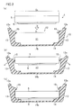
- FIG. 2(a) to FIG. 2(c) are cross-sectional views illustrating the steps of holding (i.e., containing) the battery 1 in a battery holding case (hereinafter simply referred to as a "holding case") 10.
- a battery holding case hereinafter simply referred to as a "holding case" 10.
- the positive electrode surface 5 and the negative electrode surface 6 are shown as the battery 1.
- the holding case 10 is in a resin-made box-like shape having a side portion 13 and a bottom portion 14 which hold the side surface and/or the bottom surface of the battery 1, and an open end face 13a through which the battery 1 is inserted and removed from an electrode surface of the battery 1.
- the holding case 10 has an opening 12 through which the battery 1 can be inserted and removed, and an accommodation space 11 for accommodating the battery 1.
- the side portion 13 of the holding case 10 is provided with a protrusion 15 which protrudes radially inward from an edge of the side portion 13 closer to the open end face 13a.
- the protrusion 15 is positioned at a location farther from the bottom portion of the holding case 10 than the thickness of the battery 1.
- the protrusion 15 is in a ring shape, and the inner diameter D 1 of the protrusion 15 is smaller than the outer diameter D 2 of the battery 1.
- the protrusion 15 is integrally formed with the holding case 10.
- the replaced battery 1 can be stored in the holding case 10 for collection, which can prevent a short circuit fault during the collection.
- the battery 1 is stored in the accommodation space 11 of the holding case 10 at a location closer to the bottom portion 14 than the protrusion 15, since the protrusion 15 is provided at a location farther from the bottom portion 14 of the holding case 10 than the thickness of the battery 1. This means that the positive electrode surface 5 of the battery 1 is apart from the open end face 13a of the holding case 10.
- An emetic agent may be applied to the side portion 13 of the holding case 10 and/or an outer surface of the bottom portion 14.
- the emetic agent makes the infant immediately spit the battery out, and prevents the infant from swallowing the battery into his/her body.
- no emetic agent is applied to the battery 1.
- the battery 1 does not have a poor contact when inserted in electronic devices.
- the resin material used for the holding case 10 is not limited, but it is preferable that the side portion 13 of the holding case 10 is configured by a resin material that is flexible enough to be deformed while expanding outward as shown in FIG. 2(b) .
- resin material for the holding case 10 polyolefin-based elastomer resin having similar properties as rubber can be used.
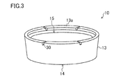
- a slit 30 in the side portion 13 near the open end face 13a of the holding case 10 as shown in the oblique view of FIG. 3 .
- the shape, the size, and the number of the slits 30 are not specifically limited, but as shown in FIG. 3 , for example, a plurality of slits 30 may be formed along the ring-shaped open end face 13a at equal intervals.
- the bottom portion 14 of the holding case 10 includes a thin portion 14b which is thinner than the other portion.
- the battery 1 can be more easily removed since the side portion 13 of the holding case 10 expands outward more easily by pushing the thin portion 14b of the bottom portion 14 of the holding case 10.
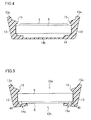
- the battery 1 is stored in the holding case 10 such that the negative electrode surface 6 of the battery 1 faces the bottom portion 14 of the holding case 10, but as shown in FIG. 4 , the battery 1 may be stored in the holding case 10 such that the positive electrode surface 5 of the battery 1 faces the bottom portion 14 of the holding case 10.
- the battery 1 is stored in the accommodation space 11 of the holding case 10 at a location closer to the bottom portion 14 than the protrusion 15, and therefore, the negative electrode surface 6 of the battery 1 is apart from the open end face 13a of the holding case 10.
- the shape of the protrusion 15 of the present embodiment is not specifically limited, and may be formed into a ring shape, or a plurality of protrusions 15 are provided along an inner circumference of the side portion of the holding case 10 at equal intervals.
- FIG. 5 shows a variation of the first embodiment of the present invention.
- the bottom portion 14 of the holding case 10 is provided with an opening 12b.
- the side portion 13 of the holding case 10 is deformed while expanding radially outward, and after the battery 1 passes by the protrusion 15, the battery 1 is held in the accommodation space 11 while being supported by the side portion 13 of the holding case 10.
- the battery 1 inserted in the accommodation space 11 does not come off through the opening 12b since an opening edge 14c of the bottom portion 14 serves as a stopper.
- the battery 1 held in the accommodation space 11 of the holding case 10 can be easily removed by pushing the battery 1 from the opening 12b of the holding case 10.
- the opening edge 14c is tilted toward the accommodation space 11 so that the opening edge 14c touches the negative electrode surface 6 (or the positive electrode surface 5) of the battery 1 and prevents saliva, etc., from entering into a gap 40 including the exposed portion of the gasket 7, as shown in FIG. 5 .
- the box-like shape of the holding case 10 is not limited to any specific shape, and may be in any shape as long as it has an open end face which allows the battery 1 to be inserted and removed from the electrode surface, and a side portion.
- the outer shape of the holding case 10 may not only be a circular shape, but may also be a polygonal shape in plan view.
- FIGS. 6(a) and 6(b) show another variation of the first embodiment of the present invention.
- the holding case 10 of the present variation is in a resin-made box-like shape having a first open end face 13a through which the battery 1 is inserted and removed from the electrode surface, and a second open end face 13b which is located opposite to the first open end face 13a and through which the battery 1 is inserted and removed from the electrode surface.
- the holding case 10 has openings 12a, 12b through which the battery 1 can be inserted and removed in two directions, and an accommodation space 11 for accommodating the battery 1.
- the side portion 13 of the holding case 10 is provided with a first protrusion 15a which protrudes radially inward from an edge of the side portion 13 closer to the first open end face 13a, and a second protrusion 15b which protrudes radially inward from an edge of the side portion 13 closer to the second open end face 13b.
- the distance between the first protrusion 15a and the second protrusion 15b is greater than the thickness of the battery 1.
- the side portion 13 of the holding case 10 is deformed while expanding radially outward, and the battery 1 is held in the accommodation space 11 while being supported by the side portion 13 of the holding case 10 as shown in FIG. 6(b) .
- the battery 1 inserted in the accommodation space 11 does not come off through the opening 12b since the protrusion 15b provided closer to the opening 12b serves as a stopper. As a result, the battery 1 is stored in the accommodation space 11 between the first protrusion 15a and the second protrusion 15b.
- the side portion 13 of the holding case 10 is provided with the protrusions 15a, 15b which protrude radially inward from the edges closer to the open end face 13a, 13b, respectively, storing the replaced battery 1 in the holding case 10 during collection can prevent a short circuit fault during the collection.
- the distance between the first protrusion 15a and the second protrusion 15b is greater than the thickness of the battery 1, the battery 1 is stored between the first protrusion 15a and the second protrusion 15b in the accommodation space 11 of the holding case 10. This means that the electrode surface of the battery 1 is apart from the open end faces 13a, 13b of the holding case 10.
- the box-like shape of the holding case 10 is not limited to any specific shape, and may be in any shape as long as it has two opposed open end faces which allow the battery 1 to be inserted and removed from the electrode surface, and a side portion.
- the outer shape of the holding case 10 may not only be a circular shape, but may also be a polygonal shape in plan view.
- the holding case 10 has an opening 12 through which the battery 1 can be inserted and removed from an electrode surface of the battery 1, and a side portion 13 and a bottom portion 14 which hold the side surface and/or the bottom surface of the battery 1.
- the holding case 10 also has a ring-shaped protrusion 15 which protrudes radially inward from an open end face 13a of the side portion 13.
- the protrusion 15 is supported on the open end face 13a in a bendable manner.
- an emetic agent is applied to the outer surfaces of the side portion 13 and/or the bottom portion 14 of the holding case 10.
- a raised portion 16 which energizes the side surface of the battery 1 is formed on the inner circumferential surface of the side portion 13 of the holding case 10.
- the shape of the raised portion 16 is not specifically limited, but as shown in FIG. 8 , four raised portions 16 may be provided on the side portion 13 of the holding case 10 with equal intervals between each other in a circumferential direction of the side portion 13, for example.
- a recessed portion 14a is formed in the bottom portion 14 of the holding case 10, for receiving the protruding electrode portion including the negative electrode surface 6.
- the periphery of the positive electrode surface 5 of the battery 1 comes in contact with the ring-shaped protrusion 15 as shown in FIG. 7(b) .
- the protrusion 15 is made of a deformable elastic member, the protrusion 15 is deformed as the battery 1 enters the accommodation space 11 of the holding case 10 as shown in FIG. 7(b) .
- the protruding electrode portion including the negative electrode surface 6 is buried in the recessed portion 14a formed in the bottom portion 14 of the holding case 10.
- the protrusion 15 After the battery 1 passes by the protrusion 15, the protrusion 15 returns to its original position due to the elasticity. In this state, the side surface of the battery 1 is held in the accommodation space 11 by being energized by the raised portion 16 formed on the side portion 13 of the holding case 10.
- an emetic agent is applied to the outer surfaces of the side portion 13 and/or the bottom portion 14 of the holding case 10 which holds the battery 1.
- the emetic agent makes the infant immediately spit the battery out, and prevents the infant from swallowing the battery into his/her body.
- no emetic agent is applied to the battery 1.
- the battery 1 does not have a poor contact when inserted in electronic devices.
- the protruding electrode portion including the negative electrode surface 6 is buried in the recessed portion 14a formed in the bottom portion 14 of the holding case 10, insulation between the negative electrode surface 6 and the positive electrode surface 5 is ensured by the bottom portion 14 of the holding case 10. Accordingly, a short circuit fault can be avoided during collection of replaced batteries 1 by accommodating the respective replaced batteries 1 in the holding case 10.
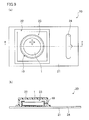
- FIG. 9 schematically shows a configuration of a battery package 20 containing the flat battery 1 according to the present embodiment.
- FIG. 9(a) is a plan view.
- FIG. 9(b) is a cross-sectional view taken along the line B-B of FIG. 9(a) .
- the battery package 20 is a blister pack including a main cover 22 which forms a containing space 23 for containing the flat battery 1, and a base 21 which closes the containing space 23 of the main cover 22.
- the flat battery 1 is contained in the containing space 23 while being held in the holding case 10.
- the base 21 is provided with a hole 24 so that the battery package 20 may be hung.
- the user who bought the battery package 20 on the market removes the holding case 10, in which the battery 1 is held, from the battery package 20, and then takes the battery 1 out of the holding case 10 before he/she inserts the battery 1 in an electronic device.
- the battery 1 can be prevented from being accidentally swallowed by an infant because the battery 1 is held in the holding case 10.
- the holding case 10 from which the battery 1 has been taken out can be used again to accommodate the replaced battery 1 during collection of the replaced battery 1. As a result, it is possible to prevent a short circuit fault during the collection of the battery.
- the battery 1 can be taken out of the holding case 10 by pushing the bottom portion 14 of the holding case 10 in a direction toward the battery 1 against the energizing force of the raised portion 16.
- the battery 1 can be taken out more easily particularly because the recessed portion 14a formed in the bottom portion 14 of the holding case 10 has a thin resin thickness.
- the protruding electrode portion including the negative electrode surface 6 is buried in the recessed portion 14a formed in the bottom portion 14 of the holding case 10. It is thus possible to prevent a short circuit fault between the positive electrode surface 5 and the negative electrode surface 6.
- FIG. 11 is an enlarged cross-sectional view of the holding case in the state shown in FIG. 10(c) .
- the battery 1 is not buried in the recessed portion 14a formed in the bottom portion 14 of the holding case 10.
- the battery 1 is held in the accommodation space 11 at a position closer to the protrusion 15 by the depth of the recessed portion 14a, compared to the position shown in FIG. 7(c) .
- the protrusion 15 overlaps the positive electrode surface 5. Accordingly, even when the replaced battery 1 is accommodated in holding case 10 for collection, it is possible to prevent a short circuit fault between the positive electrode surface 5 and the negative electrode surface 6.
- the radially inward end of the protrusion 15 is in contact with the negative electrode surface 6 of the battery 1.
- the radially inward end of the protrusion 15 is not in contact with the negative electrode surface 6, and there is some gap between the radially inward end of the protrusion 15 and the negative electrode surface 6, it is possible to prevent a short circuit fault between the positive electrode surface 5 and the negative electrode surface 6 as long as the radially inward end of the protrusion 15 overlaps with the positive electrode surface 5.
- materials for the emetic agent applied to the outer surfaces of the side portion 13 and/or the bottom portion 14 of the holding case 10 are not specifically limited as long as they are substances with a taste that makes people spit the substances out of their mouths.
- denatonium benzoate, chrysanthemum extracts, cork tree extracts, etc. can be used as bitter substances.
- Capsaicin, sinigrin, etc. can be used as pungent substances.
- the emetic agent may be mixed beforehand in the resin which forms the holding case 10.
- materials for the holding case 10 are not specifically limited.
- materials for the holding case 10 are not specifically limited.
- polypropylene (PP), polyethylene terephthalate (PET), etc. can be used as the materials for the holding case 10.
- the side portion 13, the bottom portion 14, and the protrusion 15 of the holding case 10 may be integrally formed by injection molding.
- the protrusion 15 made of a deformable elastic member may be insert molded during molding of the holding case 10.
- the flat battery 1 is held in the holding case 10, and in this state the flat battery 1 is contained in the containing space 23 of the battery package 20, such as a blister pack. Further, a function for preventing accidental swallowing and a function for preventing a short circuit are added to the holding case 10 to avoid accidental swallowing and a short circuit fault.
- the holding case 10 can be achieved in a very simple configuration. Moreover, the dimensions of the holding case 10 are determined according to battery specifications. Thus, the holding case 10 is highly versatile, and therefore, the resin case 10 can not only be used in the battery package 20, but also be used as a holding case 10 for holding a battery.
- FIG. 12 is an oblique view of a variation of the holding case 10 according to the present embodiment.
- the holding case 10 shown in FIG. 7(a) and FIG. 8 has a function for preventing accidental swallowing by applying an emetic agent to the outer surfaces of the side portion 13 and/or the bottom portion 14 of the holding case 10.
- the holding case 10 itself has a rectangular outer shape to give the holding case 10 the function for preventing accidental swallowing.
- the open end face of the holding case 10 shown in FIG. 12 through which the battery 1 is inserted and removed is in a circular shape whose diameter is almost the same as the diameter of the positive electrode surface 5 of the battery 1, and includes a ring-shaped protrusion 15 which protrudes radially inward from an edge of the open end face.
- the side portion 13 of the holding case 10 is in a quadrangle shape in plan view.
- the infant who accidentally puts the holding case 10 holding the battery 1 in his/her mouth may feel uncomfortable in the mouth since the holding case 10 is in a square shape. It is therefore possible to prevent the infant from swallowing the battery into his/her body.
- the outer shape of the holding case 10 is not limited to a quadrangle shape in plan view, but may be a polygonal shape.
- FIG. 13 is a cross-sectional view of another variation of the holding case 10 according to the present embodiment.
- the holding case 10 has an opening 12 through which the battery 1 is inserted and removed from the electrode surface of the battery 1, a side portion 13 and a bottom portion 14 which hold the side surface and/or the bottom surface of the battery 1, and three ring-shaped protrusions 15a, 15b, 15c which protrude radially inward from the side portion 13.
- Each of the protrusions 15a, 15b, 15c is supported on the side portion 13 in a bendable manner, and the inner diameter of each of the protrusions 15a, 15b, 15c is smaller than the inner diameter of the exposed portion of the gasket (not shown).
- a thin portion 14b with a reduced thickness is formed at a central portion of the bottom portion 14.
- a tapered surface 17 is formed at a corner formed by the side portion 13 and the bottom portion 14.
- FIGS. 14(a) and 14(b) show cross-sectional views illustrating the steps for holding (i.e., containing) three types of batteries A, B, C having different thicknesses in the holding case 10.
- the protrusion 15a overlaps the positive electrode surface 5 of the battery A.
- the other protrusions 15b, 15c are deformed and hold the battery A by energizing the side surface of the battery A. That is, in the present variation, the protrusion 15a corresponds to the protrusion 15 shown in FIGS. 7(a) and FIG. 8 , and the protrusions 15b, 15c correspond to the raised portion 16 shown in FIGS. 7(a) and FIG. 8 .
- the protrusion 15b overlaps the positive electrode surface 5 of the battery B, and the protrusion 15c overlaps the positive electrode surface 5 of the battery C.
- a plurality of protrusions 15 are provided at different heights of the side portion 13 of the holding case 10.
- one of the protrusions 15 may overlap the positive electrode surface 5 of the battery 1.
- the protrusion 15 can overlap the positive electrode surface 5 of the battery 1 when the battery 1 is inserted in the holding case 10 from the positive electrode surface 5 as shown in FIGS. 10(a) to 10(c) .
- the battery 1 accommodated in the holding case 10 can be easily taken out of the holding case 10 by pushing the thin portion 14b formed in the bottom portion 14 of holding case 10.
- a blister pack is used as an example of the battery package.
- the battery package is not limited to the blister pack, but may be a pillow package, etc., made of tubular package film, for example.
- the present invention is useful as a battery holding case for accommodating a flat battery used as a power source of an electronic device.
Landscapes
- Chemical & Material Sciences (AREA)
- Chemical Kinetics & Catalysis (AREA)
- Electrochemistry (AREA)
- General Chemical & Material Sciences (AREA)
- Engineering & Computer Science (AREA)
- Manufacturing & Machinery (AREA)
- Battery Mounting, Suspending (AREA)
- Sealing Battery Cases Or Jackets (AREA)
Abstract
Description
- The present invention relates to battery holding cases for holding a disk-like flat batteries, and battery packages having a containing space for containing the battery holding case.
- Disc-like flat batteries, such as coin batteries, etc., are thin and small, and therefore, infants may accidentally swallow them.
- Thus, to avoid the accidental swallowing, electronic devices using a coin battery as a power source include a lock mechanism that locks the containing space for containing the coin battery so that the coin battery cannot be easily removed by infants.
- However, if a coin battery is removed from the battery package in which the coin battery has been stored, but left unattended without replacement of batteries, or an infant brakes the blister pack by himself/herself, there is a possibility that infants may accidentally swallow the coin battery. Further, when a coin battery is accidentally swallowed, saliva may cause the electrolysis of water, which generates an alkaline liquid from the coin battery, and this may cause damage to the body.
- Further, although the replaced coin batteries are suggested to be insulated before disposal, such as adhering resin tape to avoid a short circuit, if a lot of naked coin batteries are left uninsulated and piled in a collecting box, batteries overlapping each other may be bridged and form a circuit, and may cause a short circuit. Especially in the case where the coin batteries have a remaining capacity, the short circuit may lead to heat generation, explosion, or liquid leakage.
- To avoid this,
Patent Document 1, for example, discloses applying substances such as bitter agents, which infants dislike, to a surface of the coin battery so that infants who accidentally put a coin battery in their mouths may immediately spit the battery out to avoid swallowing of the battery into their bodies. -
Patent Document 2 discloses covering the coin battery, except an electrode terminal, with an insulator having a rectangular outer shape so that infants who accidentally put a coin battery in their mouths may feel uncomfortable in their mouths to avoid swallowing of the battery into their bodies. -
- Patent Document 1: Japanese Patent Publication No.
S59-44762 - Patent Document 2: Japanese Utility Model Publication No.
S59-192262 - If the substances such as bitter agents are applied to the surface of the coin battery, the coin battery may have a poor contact when inserted in the electronic devices.
- Further, if the coin battery is covered with a rectangular insulator, it changes the outer dimensions of the coin battery. Accordingly, the coin battery is less versatile, and can only be used in a limited range of electronic devices.
- Moreover, effective solutions for a short circuit fault during collection of naked coin batteries have not yet been developed. In particular, if a plurality of coin batteries overlap one another, with the positive electrodes and the negative electrodes of the respective coin batteries touching each other, a short circuit chain occurs in the plurality of coin batteries, and therefore, heat may be generated due to a short circuit current, which may lead to ignition.
- The present invention was made in view of the above problems, and it is a main objective of the invention to provide a battery holding case which can avoid accidental swallowing of a disk-like flat battery and significantly reduce damage to a body even in the event of accidental swallowing, and moreover a battery holding case which can avoid a short circuit fault during collection of the disk-like flat batteries.
- A battery holding case of the present invention for holding a disk-like flat battery, wherein the flat battery is configured such that a sealing plate which also serves as a first electrode surface hermetically seals a battery case which also serves as a second electrode surface, with a ring-shaped gasket interposed between the battery case and the sealing plate, the holding case is in a resin-made box-like shape having an open end face through which the flat battery can be inserted and removed from an electrode surface of the flat battery, a side portion of the holding case is provided with a protrusion which protrudes radially inward from an edge of the side portion closer to the open end face, and the protrusion is positioned at a location farther from a bottom portion of the holding case than a thickness of the flat battery.
- In the above configuration, the side portion of the holding case is provided with a protrusion which protrudes radially inward from an edge of the side portion closer to the open end face. Thus, storing the replaced battery in the holding case during collection can prevent a short circuit fault, particularly a short circuit chain, during the collection.
- In the battery package according to the present invention, the flat battery is held in the battery holding case, and in this state the flat battery is contained in the containing space of the battery package. The user who bought this battery package on the market removes the battery holding case, which holds the flat battery, from the battery package, and then takes the battery out of the battery holding case before he/she inserts the battery in an electronic device. Thus, even if the flat battery removed from the battery package is left unattended until it is inserted in the electronic device, the battery can be prevented from being accidentally swallowed by an infant because the battery is held in the battery holding case. In addition, even in the event of accidental swallowing, the battery is protected from contact with a liquid, such as saliva, which therefore reduces the possibility of generation of an alkaline liquid and significantly reduces damage to the body. Moreover, the waste battery replaced by a new battery can be immediately stored in the empty battery holding case in which the new battery was stored, thereby making it possible to prevent a short circuit fault in collecting the batteries.
- According to the present invention, it is possible to provide a battery holding case of a simple structure which can serve as a measure for preventing accidental swallowing of a battery and a measure for reducing damage to a body, and can prevent a short circuit fault in collecting disk-like flat batteries.
-
-
FIG. 1 is a cross-sectional view of a configuration of a disk-like flat battery according to the first embodiment of the present invention. -
FIG. 2(a) to FIG. 2(c) show cross-sectional views illustrating the steps of holding the battery of the first embodiment of the present invention in a holding case. -
FIG. 3 is an oblique view of another configuration of the holding case of the first embodiment of the present invention. -
FIG. 4 is a cross-sectional view of the holding case holding a battery. -
FIG. 5 is a cross-sectional view of a variation of the first embodiment of the present invention. -
FIG. 6(a) to FIG. 6(c) show cross-sectional views of a variation of the first embodiment of the present invention. -
FIG. 7(a) to FIG. 7(c) show cross-sectional views illustrating the steps of holding a battery of the second embodiment of the present invention in a holding case. -
FIG. 8 is a plan view of a configuration of the holding case of the second embodiment of the present invention. -
FIG. 9 illustrates a configuration of a battery package of the second embodiment of the present invention.FIG. 9(a) is a plan view.FIG. 9(b) is a cross-sectional view taken along the line B-B ofFIG. 9(a) . -
FIG. 10(a) to FIG. 10(c) show cross-sectional views illustrating other steps of holding the battery of the second embodiment of the present invention in the holding case. -
FIG. 11 is a cross-sectional view of the enlarged holding case in the state shown inFIG. 10(c) . -
FIG. 12 is an oblique view showing a variation of the holding case of the second embodiment of the present invention. -
FIG. 13 is a cross-sectional view of another variation of the holding case of the second embodiment of the present invention. -
FIG. 14(a) and FIG. 14(b) show cross-sectional views illustrating the steps of holding batteries with different thicknesses in the holding case. - Embodiments of the present invention will be described in detail below based on the drawings. The present invention is not limited to the embodiments below. Further, the embodiments can be properly modified without deviating from the effective scope of the present invention.
- (First Embodiment)
-
FIG. 1 is a cross-sectional view which schematically illustrates a configuration of a disk-likeflat battery 1 according to the first embodiment of the present invention. The disc-likeflat battery 1 is a thin, disc-like battery, such as a coin battery. The battery may be any type. For example, the battery may be a primary battery or a secondary battery. Hereinafter, the disc-likeflat battery 1 is simply referred to as a "battery." The battery shown inFIG. 1 as an example is a lithium battery. - As shown in
FIG. 1 , anegative electrode 2 having lithium or a lithium alloy as a negative electrode active material, and apositive electrode 3 having graphite fluoride as a positive electrode active material, with a separator 4 interposed therebetween, are housed in abattery case 5 together with an electrolyte. The opening of thebattery case 5 is sealed with asealing plate 6 via aring gasket 7. Thepositive electrode 3 is in contact with a bottom of thebattery case 5, and the bottom of thebattery case 5 also serves as a positive electrode surface. Thenegative electrode 2 is in contact with the sealingplate 6, and an upper surface of the sealingplate 6 also serves as a negative electrode surface. The outer diameter of thenegative electrode surface 6 is smaller than the outer diameter of thepositive electrode surface 5, and a negative electrode terminal forms a protruding electrode portion. -
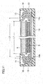
FIG. 2(a) to FIG. 2(c) are cross-sectional views illustrating the steps of holding (i.e., containing) thebattery 1 in a battery holding case (hereinafter simply referred to as a "holding case") 10. Here, only thepositive electrode surface 5 and thenegative electrode surface 6 are shown as thebattery 1. - As shown in
FIG. 2(a) , the holdingcase 10 is in a resin-made box-like shape having aside portion 13 and abottom portion 14 which hold the side surface and/or the bottom surface of thebattery 1, and anopen end face 13a through which thebattery 1 is inserted and removed from an electrode surface of thebattery 1. This means that the holdingcase 10 has anopening 12 through which thebattery 1 can be inserted and removed, and anaccommodation space 11 for accommodating thebattery 1. Theside portion 13 of the holdingcase 10 is provided with aprotrusion 15 which protrudes radially inward from an edge of theside portion 13 closer to theopen end face 13a. Theprotrusion 15 is positioned at a location farther from the bottom portion of the holdingcase 10 than the thickness of thebattery 1. Further, theprotrusion 15 is in a ring shape, and the inner diameter D1 of theprotrusion 15 is smaller than the outer diameter D2 of thebattery 1. Moreover, theprotrusion 15 is integrally formed with the holdingcase 10. - When the
battery 1 is inserted in theaccommodation space 11 of the holdingcase 10 in the arrow direction as shown inFIG. 2(a) , the periphery of thepositive electrode surface 5 of thebattery 1 comes in contact with theprotrusion 15 as shown inFIG. 2(b) . As shown inFIG. 2(b) , if the holdingcase 10 is made of a deformable elastic member, theside portion 13 of the holdingcase 10 is deformed while expanding radially outward as thebattery 1 enters theaccommodation space 11 of the holdingcase 10. As shown inFIG. 2(c) , after thebattery 1 passes by theprotrusion 15, theside portion 13 returns to its original position due to the elasticity. Thebattery 1 is held in theaccommodation space 11 while being supported by theside portion 13 of the holdingcase 10. - In the present invention, since the side portion of the holding
case 10 is provided with theprotrusion 15 protruding radially inward from the edge of the side portion closer to theopen end face 13a, the replacedbattery 1 can be stored in the holdingcase 10 for collection, which can prevent a short circuit fault during the collection. In particular, thebattery 1 is stored in theaccommodation space 11 of the holdingcase 10 at a location closer to thebottom portion 14 than theprotrusion 15, since theprotrusion 15 is provided at a location farther from thebottom portion 14 of the holdingcase 10 than the thickness of thebattery 1. This means that thepositive electrode surface 5 of thebattery 1 is apart from theopen end face 13a of the holdingcase 10. Thus, even if the holdingcases 10 overlap one another during the collection, it is possible to prevent a short circuit fault due to contact between thebatteries 1. - An emetic agent may be applied to the
side portion 13 of the holdingcase 10 and/or an outer surface of thebottom portion 14. Thus, even if an infant accidentally puts thebattery 1 in his/her mouth, the emetic agent makes the infant immediately spit the battery out, and prevents the infant from swallowing the battery into his/her body. Here, no emetic agent is applied to thebattery 1. Thus, thebattery 1 does not have a poor contact when inserted in electronic devices. - In the present embodiment, the resin material used for the holding
case 10 is not limited, but it is preferable that theside portion 13 of the holdingcase 10 is configured by a resin material that is flexible enough to be deformed while expanding outward as shown inFIG. 2(b) . As an example resin material for the holdingcase 10, polyolefin-based elastomer resin having similar properties as rubber can be used. - Further, in order to make the
side portion 13 of the holdingcase 10 more deformable, it is preferable to form aslit 30 in theside portion 13 near theopen end face 13a of the holdingcase 10 as shown in the oblique view ofFIG. 3 . The shape, the size, and the number of theslits 30 are not specifically limited, but as shown inFIG. 3 , for example, a plurality ofslits 30 may be formed along the ring-shapedopen end face 13a at equal intervals. - Further, as shown in
FIG. 2(c) , it is preferable that thebottom portion 14 of the holdingcase 10 includes athin portion 14b which is thinner than the other portion. Thus, in taking thebattery 1 out of the holdingcase 10, thebattery 1 can be more easily removed since theside portion 13 of the holdingcase 10 expands outward more easily by pushing thethin portion 14b of thebottom portion 14 of the holdingcase 10. - In
FIG. 2(c) , thebattery 1 is stored in the holdingcase 10 such that thenegative electrode surface 6 of thebattery 1 faces thebottom portion 14 of the holdingcase 10, but as shown inFIG. 4 , thebattery 1 may be stored in the holdingcase 10 such that thepositive electrode surface 5 of thebattery 1 faces thebottom portion 14 of the holdingcase 10. In this case, as well, thebattery 1 is stored in theaccommodation space 11 of the holdingcase 10 at a location closer to thebottom portion 14 than theprotrusion 15, and therefore, thenegative electrode surface 6 of thebattery 1 is apart from theopen end face 13a of the holdingcase 10. Thus, even if the holdingcases 10 overlap one another during the collection, it is possible to prevent a short circuit fault due to contact between thebatteries 1. - The shape of the
protrusion 15 of the present embodiment is not specifically limited, and may be formed into a ring shape, or a plurality ofprotrusions 15 are provided along an inner circumference of the side portion of the holdingcase 10 at equal intervals. -
FIG. 5 shows a variation of the first embodiment of the present invention. - As shown in
FIG. 5 , in the present variation, thebottom portion 14 of the holdingcase 10 is provided with anopening 12b. When thebattery 1 is inserted into theaccommodation space 11 of the holdingcase 10 from theopening 12a in a similar manner as illustrated inFIGS. 2(a) to 2(c) , theside portion 13 of the holdingcase 10 is deformed while expanding radially outward, and after thebattery 1 passes by theprotrusion 15, thebattery 1 is held in theaccommodation space 11 while being supported by theside portion 13 of the holdingcase 10. Thebattery 1 inserted in theaccommodation space 11 does not come off through theopening 12b since anopening edge 14c of thebottom portion 14 serves as a stopper. - In the present variation, the
battery 1 held in theaccommodation space 11 of the holdingcase 10 can be easily removed by pushing thebattery 1 from theopening 12b of the holdingcase 10. - In the event of accidental swallowing of the holding
case 10 holding thebattery 1, the electrolysis of water due to saliva, etc., occurs near the sealed portion where thegasket 7 is exposed, in thebattery 1 shown inFIG. 1 . Thus, to avoid damage from the electrolysis to a body in the event of the above accidental swallowing, it is preferable that the openingedge 14c is tilted toward theaccommodation space 11 so that the openingedge 14c touches the negative electrode surface 6 (or the positive electrode surface 5) of thebattery 1 and prevents saliva, etc., from entering into agap 40 including the exposed portion of thegasket 7, as shown inFIG. 5 . - In the present embodiment, the box-like shape of the holding
case 10 is not limited to any specific shape, and may be in any shape as long as it has an open end face which allows thebattery 1 to be inserted and removed from the electrode surface, and a side portion. For example, the outer shape of the holdingcase 10 may not only be a circular shape, but may also be a polygonal shape in plan view. -
FIGS. 6(a) and 6(b) show another variation of the first embodiment of the present invention. - As shown in
FIG. 6(a) , the holdingcase 10 of the present variation is in a resin-made box-like shape having a firstopen end face 13a through which thebattery 1 is inserted and removed from the electrode surface, and a secondopen end face 13b which is located opposite to the firstopen end face 13a and through which thebattery 1 is inserted and removed from the electrode surface. This means that the holdingcase 10 hasopenings battery 1 can be inserted and removed in two directions, and anaccommodation space 11 for accommodating thebattery 1. Theside portion 13 of the holdingcase 10 is provided with afirst protrusion 15a which protrudes radially inward from an edge of theside portion 13 closer to the firstopen end face 13a, and asecond protrusion 15b which protrudes radially inward from an edge of theside portion 13 closer to the secondopen end face 13b. The distance between thefirst protrusion 15a and thesecond protrusion 15b is greater than the thickness of thebattery 1. - As shown in
FIG. 6(a) , when thebattery 1 is inserted in theaccommodation space 11 of the holdingcase 10 in the arrow direction from theopening 12a, for example, theside portion 13 of the holdingcase 10 is deformed while expanding radially outward, and thebattery 1 is held in theaccommodation space 11 while being supported by theside portion 13 of the holdingcase 10 as shown inFIG. 6(b) . Thebattery 1 inserted in theaccommodation space 11 does not come off through theopening 12b since theprotrusion 15b provided closer to theopening 12b serves as a stopper. As a result, thebattery 1 is stored in theaccommodation space 11 between thefirst protrusion 15a and thesecond protrusion 15b. - In the present variation, since the
side portion 13 of the holdingcase 10 is provided with theprotrusions open end face battery 1 in the holdingcase 10 during collection can prevent a short circuit fault during the collection. In particular, since the distance between thefirst protrusion 15a and thesecond protrusion 15b is greater than the thickness of thebattery 1, thebattery 1 is stored between thefirst protrusion 15a and thesecond protrusion 15b in theaccommodation space 11 of the holdingcase 10. This means that the electrode surface of thebattery 1 is apart from the open end faces 13a, 13b of the holdingcase 10. Thus, even if the holdingcases 10 overlap one another during the collection, it is possible to prevent a short circuit fault due to contact between thebatteries 1. - In the present variation, the box-like shape of the holding
case 10 is not limited to any specific shape, and may be in any shape as long as it has two opposed open end faces which allow thebattery 1 to be inserted and removed from the electrode surface, and a side portion. For example, the outer shape of the holdingcase 10 may not only be a circular shape, but may also be a polygonal shape in plan view. - As shown in
FIG. 7(a) andFIG. 8 , the holdingcase 10 has anopening 12 through which thebattery 1 can be inserted and removed from an electrode surface of thebattery 1, and aside portion 13 and abottom portion 14 which hold the side surface and/or the bottom surface of thebattery 1. This means that anaccommodation space 11 for accommodating thebattery 1 is formed in the holdingcase 10. The holdingcase 10 also has a ring-shapedprotrusion 15 which protrudes radially inward from anopen end face 13a of theside portion 13. Theprotrusion 15 is supported on theopen end face 13a in a bendable manner. Further, an emetic agent is applied to the outer surfaces of theside portion 13 and/or thebottom portion 14 of the holdingcase 10. - A raised
portion 16 which energizes the side surface of thebattery 1 is formed on the inner circumferential surface of theside portion 13 of the holdingcase 10. The shape of the raisedportion 16 is not specifically limited, but as shown inFIG. 8 , four raisedportions 16 may be provided on theside portion 13 of the holdingcase 10 with equal intervals between each other in a circumferential direction of theside portion 13, for example. Further, a recessedportion 14a is formed in thebottom portion 14 of the holdingcase 10, for receiving the protruding electrode portion including thenegative electrode surface 6. - When the
battery 1 is inserted in theaccommodation space 11 of the holdingcase 10 in the arrow direction as shown inFIG. 7(a) , the periphery of thepositive electrode surface 5 of thebattery 1 comes in contact with the ring-shapedprotrusion 15 as shown inFIG. 7(b) . If theprotrusion 15 is made of a deformable elastic member, theprotrusion 15 is deformed as thebattery 1 enters theaccommodation space 11 of the holdingcase 10 as shown inFIG. 7(b) . Then, as shown inFIG. 7(c) , the protruding electrode portion including thenegative electrode surface 6 is buried in the recessedportion 14a formed in thebottom portion 14 of the holdingcase 10. After thebattery 1 passes by theprotrusion 15, theprotrusion 15 returns to its original position due to the elasticity. In this state, the side surface of thebattery 1 is held in theaccommodation space 11 by being energized by the raisedportion 16 formed on theside portion 13 of the holdingcase 10. - In the present embodiment, an emetic agent is applied to the outer surfaces of the
side portion 13 and/or thebottom portion 14 of the holdingcase 10 which holds thebattery 1. Thus, even if an infant accidentally puts thebattery 1 in his/her mouth, the emetic agent makes the infant immediately spit the battery out, and prevents the infant from swallowing the battery into his/her body. Here, no emetic agent is applied to thebattery 1. Thus, thebattery 1 does not have a poor contact when inserted in electronic devices. - Further, since the protruding electrode portion including the
negative electrode surface 6 is buried in the recessedportion 14a formed in thebottom portion 14 of the holdingcase 10, insulation between thenegative electrode surface 6 and thepositive electrode surface 5 is ensured by thebottom portion 14 of the holdingcase 10. Accordingly, a short circuit fault can be avoided during collection of replacedbatteries 1 by accommodating the respective replacedbatteries 1 in the holdingcase 10. -
FIG. 9 schematically shows a configuration of abattery package 20 containing theflat battery 1 according to the present embodiment.FIG. 9(a) is a plan view.FIG. 9(b) is a cross-sectional view taken along the line B-B ofFIG. 9(a) . - As shown in
FIGS. 9(a) and 9(b) , thebattery package 20 is a blister pack including amain cover 22 which forms a containingspace 23 for containing theflat battery 1, and a base 21 which closes the containingspace 23 of themain cover 22. Theflat battery 1 is contained in the containingspace 23 while being held in the holdingcase 10. Thebase 21 is provided with ahole 24 so that thebattery package 20 may be hung. - The user who bought the
battery package 20 on the market removes the holdingcase 10, in which thebattery 1 is held, from thebattery package 20, and then takes thebattery 1 out of the holdingcase 10 before he/she inserts thebattery 1 in an electronic device. Thus, even if thebattery 1 removed from thebattery package 20 is left unattended until it is inserted in the electronic device, thebattery 1 can be prevented from being accidentally swallowed by an infant because thebattery 1 is held in the holdingcase 10. Further, the holdingcase 10 from which thebattery 1 has been taken out can be used again to accommodate the replacedbattery 1 during collection of the replacedbattery 1. As a result, it is possible to prevent a short circuit fault during the collection of the battery. - The
battery 1 can be taken out of the holdingcase 10 by pushing thebottom portion 14 of the holdingcase 10 in a direction toward thebattery 1 against the energizing force of the raisedportion 16. Thebattery 1 can be taken out more easily particularly because the recessedportion 14a formed in thebottom portion 14 of the holdingcase 10 has a thin resin thickness. - When the
battery 1 is inserted from thenegative electrode surface 6 as shown inFIGS. 7(a) to 7(c) , the protruding electrode portion including thenegative electrode surface 6 is buried in the recessedportion 14a formed in thebottom portion 14 of the holdingcase 10. It is thus possible to prevent a short circuit fault between thepositive electrode surface 5 and thenegative electrode surface 6. - However, it may happen that the user inserts the
battery 1 from thepositive electrode surface 5 as shown inFIGS. 10(a) to 10(c) . - In the present invention, it is possible to prevent a short circuit fault between the
positive electrode surface 5 and thenegative electrode surface 6 in such a situation as well. Explanation will be made below with reference toFIGS. 10(a) to 10(c) . - First, when the
battery 1 is inserted in theaccommodation space 11 of the holdingcase 10 in the arrow direction as shown inFIG. 10(a) , the periphery of thepositive electrode surface 5 of thebattery 1 comes in contact with the ring-shapedprotrusion 15, and theprotrusion 15 is deformed as shown inFIG. 10(b) . Then, as shown inFIG. 10(c) , thepositive electrode surface 5 comes in contact with thebottom portion 14 of the holdingcase 10 and stops there, because the outer diameter of thepositive electrode surface 5 is greater than the outer diameter of thenegative electrode surface 6. After thebattery 1 passes by theprotrusion 15, theprotrusion 15 returns to its original position due to the elasticity. In this state, the side surface of thebattery 1 is held in theaccommodation space 11 by being energized by the raisedportion 16 formed on theside portion 13 of the holdingcase 10. -
FIG. 11 is an enlarged cross-sectional view of the holding case in the state shown inFIG. 10(c) . - As shown in
FIG. 11 , thebattery 1 is not buried in the recessedportion 14a formed in thebottom portion 14 of the holdingcase 10. Thus, thebattery 1 is held in theaccommodation space 11 at a position closer to theprotrusion 15 by the depth of the recessedportion 14a, compared to the position shown inFIG. 7(c) . - As shown in
FIG. 11 , if the inner diameter L1 of theprotrusion 15 is smaller than the inner diameter L2 of an exposed portion of thegasket 7, theprotrusion 15 overlaps thepositive electrode surface 5. Accordingly, even when the replacedbattery 1 is accommodated in holdingcase 10 for collection, it is possible to prevent a short circuit fault between thepositive electrode surface 5 and thenegative electrode surface 6. - In
FIG. 11 , the radially inward end of theprotrusion 15 is in contact with thenegative electrode surface 6 of thebattery 1. However, even if the radially inward end of theprotrusion 15 is not in contact with thenegative electrode surface 6, and there is some gap between the radially inward end of theprotrusion 15 and thenegative electrode surface 6, it is possible to prevent a short circuit fault between thepositive electrode surface 5 and thenegative electrode surface 6 as long as the radially inward end of theprotrusion 15 overlaps with thepositive electrode surface 5. - In the present embodiment, materials for the emetic agent applied to the outer surfaces of the
side portion 13 and/or thebottom portion 14 of the holdingcase 10 are not specifically limited as long as they are substances with a taste that makes people spit the substances out of their mouths. For example, denatonium benzoate, chrysanthemum extracts, cork tree extracts, etc., can be used as bitter substances. Capsaicin, sinigrin, etc., can be used as pungent substances. Instead of applying the emetic agent to the outer surfaces of the holdingcase 10, the emetic agent may be mixed beforehand in the resin which forms the holdingcase 10. - In the present embodiment, materials for the holding
case 10 are not specifically limited. For example, polypropylene (PP), polyethylene terephthalate (PET), etc., can be used as the materials for the holdingcase 10. Theside portion 13, thebottom portion 14, and theprotrusion 15 of the holdingcase 10 may be integrally formed by injection molding. Alternatively, theprotrusion 15 made of a deformable elastic member may be insert molded during molding of the holdingcase 10. - Further, directions, etc., for use of the
flat battery 1 may be shown on thebottom portion 14 of the holdingcase 10. For example, safety cautions (regarding accidental swallowing, short circuits, etc.) may be shown on thebottom portion 14 of the holdingcase 10. - In the present invention, the
flat battery 1 is held in the holdingcase 10, and in this state theflat battery 1 is contained in the containingspace 23 of thebattery package 20, such as a blister pack. Further, a function for preventing accidental swallowing and a function for preventing a short circuit are added to the holdingcase 10 to avoid accidental swallowing and a short circuit fault. The holdingcase 10 can be achieved in a very simple configuration. Moreover, the dimensions of the holdingcase 10 are determined according to battery specifications. Thus, the holdingcase 10 is highly versatile, and therefore, theresin case 10 can not only be used in thebattery package 20, but also be used as a holdingcase 10 for holding a battery. -
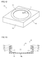
FIG. 12 is an oblique view of a variation of the holdingcase 10 according to the present embodiment. - The holding
case 10 shown inFIG. 7(a) andFIG. 8 has a function for preventing accidental swallowing by applying an emetic agent to the outer surfaces of theside portion 13 and/or thebottom portion 14 of the holdingcase 10. However, in the present variation, the holdingcase 10 itself has a rectangular outer shape to give the holdingcase 10 the function for preventing accidental swallowing. - The open end face of the holding
case 10 shown inFIG. 12 through which thebattery 1 is inserted and removed is in a circular shape whose diameter is almost the same as the diameter of thepositive electrode surface 5 of thebattery 1, and includes a ring-shapedprotrusion 15 which protrudes radially inward from an edge of the open end face. On the other hand, theside portion 13 of the holdingcase 10 is in a quadrangle shape in plan view. - According to the present variation, the infant who accidentally puts the holding
case 10 holding thebattery 1 in his/her mouth may feel uncomfortable in the mouth since the holdingcase 10 is in a square shape. It is therefore possible to prevent the infant from swallowing the battery into his/her body. The outer shape of the holdingcase 10 is not limited to a quadrangle shape in plan view, but may be a polygonal shape. -
FIG. 13 is a cross-sectional view of another variation of the holdingcase 10 according to the present embodiment. - As shown in
FIG. 13 , the holdingcase 10 has anopening 12 through which thebattery 1 is inserted and removed from the electrode surface of thebattery 1, aside portion 13 and abottom portion 14 which hold the side surface and/or the bottom surface of thebattery 1, and three ring-shapedprotrusions side portion 13. Each of theprotrusions side portion 13 in a bendable manner, and the inner diameter of each of theprotrusions thin portion 14b with a reduced thickness is formed at a central portion of thebottom portion 14. A taperedsurface 17 is formed at a corner formed by theside portion 13 and thebottom portion 14. -
FIGS. 14(a) and 14(b) show cross-sectional views illustrating the steps for holding (i.e., containing) three types of batteries A, B, C having different thicknesses in the holdingcase 10. - As shown in
FIG. 14(b) , when the thickest battery A is contained in the holdingcase 10, theprotrusion 15a overlaps thepositive electrode surface 5 of the battery A. Theother protrusions protrusion 15a corresponds to theprotrusion 15 shown inFIGS. 7(a) andFIG. 8 , and theprotrusions portion 16 shown inFIGS. 7(a) andFIG. 8 . - As shown in
FIG. 14(b) , when each of the batteries B, C with smaller thicknesses than the thickness of the battery A is contained in the holdingcase 10, theprotrusion 15b overlaps thepositive electrode surface 5 of the battery B, and theprotrusion 15c overlaps thepositive electrode surface 5 of the battery C. - As described above, a plurality of
protrusions 15 are provided at different heights of theside portion 13 of the holdingcase 10. Thus, even ifbatteries 1 with different thicknesses are used, one of theprotrusions 15 may overlap thepositive electrode surface 5 of thebattery 1. This is particularly advantageous in preventing a short circuit fault during collection of a replacedbattery 1 because theprotrusion 15 can overlap thepositive electrode surface 5 of thebattery 1 when thebattery 1 is inserted in the holdingcase 10 from thepositive electrode surface 5 as shown inFIGS. 10(a) to 10(c) . Further, thebattery 1 accommodated in the holdingcase 10 can be easily taken out of the holdingcase 10 by pushing thethin portion 14b formed in thebottom portion 14 of holdingcase 10. - The above embodiments have been described for the understanding of the present invention. However, the present invention is not limited to these descriptions, and of course, capable of various modifications. For example, in the above embodiments, a blister pack is used as an example of the battery package. However, the battery package is not limited to the blister pack, but may be a pillow package, etc., made of tubular package film, for example.
- The present invention is useful as a battery holding case for accommodating a flat battery used as a power source of an electronic device.
-
- 1
- flat battery
- 2
- negative electrode
- 3
- positive electrode
- 4
- separator
- 5
- battery case (positive electrode surface)
- 6
- sealing plate (negative electrode surface)
- 7
- gasket
- 10
- holding case
- 11
- accommodation space
- 12, 12a, 12b
- opening
- 13
- side portion
- 13a, 13b
- open end face
- 14
- bottom portion
- 14a
- recessed portion
- 14b
- thin portion
- 15, 15a, 15b, 15c
- protrusion
- 16
- raised portion
- 17
- tapered surface
- 20
- battery package
- 21
- base
- 22
- main cover
- 23
- containing space
- 24
- hole
- 30
- slit
Claims (11)
- A battery holding case for holding a disk-like flat battery, wherein
the flat battery is configured such that a sealing plate which also serves as a first electrode surface hermetically seals a battery case which also serves as a second electrode surface, with a ring-shaped gasket interposed between the battery case and the sealing plate,
the holding case is in a resin-made box-like shape having an open end face through which the flat battery can be inserted and removed from an electrode surface of the flat battery,
a side portion of the holding case is provided with a protrusion which protrudes radially inward from an edge of the side portion closer to the open end face, and
the protrusion is positioned at a location farther from a bottom portion of the holding case than a thickness of the flat battery. - The battery holding case of claim 1, wherein
the protrusion is a ring shape, and
an inner diameter of the protrusion is smaller than an outer diameter of the flat battery. - The battery holding case of claim 1, wherein
a slit is formed in the side portion of the holding case near the open end face. - The battery holding case of claim 1, wherein
the protrusion is integrally formed with the holding case. - The battery holding case of claim 1, wherein
the bottom portion of the holding case includes a thin portion which is thinner than the other portion. - The battery holding case of claim 1, wherein
the holding case is in a resin-made box-like shape having a first open end face through which the flat battery can be inserted and removed from the electrode surface of the flat battery, and a second open end face which is located opposite to the first open end face and through which the flat battery can be inserted and removed from the electrode surface of the flat battery,
the side portion of the holding case is provided with a first protrusion which protrudes radially inward from an edge of the side portion closer to the first open end face, and a second protrusion which protrudes radially inward from an edge of the side portion closer to the second open end face, and
a distance between the first protrusion and the second protrusion is greater than the thickness of the flat battery. - The battery holding case of claim 1, wherein
an emetic agent is applied to an outer surface of the side portion and/or the bottom portion of the holding case. - The battery holding case of claim 1, wherein
a direction for use of the flat battery is shown on an outer surface of the bottom portion of the holding case. - The battery holding case of claim 2, wherein
the protrusion is supported on an edge of the holding case closer to the open end face in a bendable manner. - The battery holding case of claim 1, wherein
an inner diameter of the protrusion is smaller than an inner diameter of an exposed portion of the gasket. - A battery package, comprising:a containing space for containing a flat battery held in the battery holding case of any one of claims 1-10, whereinthe battery package is a blister pack including
a main cover which forms the containing space for containing the flat battery, and
a base which closes a recessed portion of the main cover.
Applications Claiming Priority (2)
| Application Number | Priority Date | Filing Date | Title |
|---|---|---|---|
| JP2012166748A JP2014026848A (en) | 2012-07-27 | 2012-07-27 | Cell container and resin case for containing cell used therefor |
| PCT/JP2013/004552 WO2014017103A1 (en) | 2012-07-27 | 2013-07-26 | Cell holding case and cell packaging body provided with housing chamber for housing same |
Publications (1)
| Publication Number | Publication Date |
|---|---|
| EP2879200A1 true EP2879200A1 (en) | 2015-06-03 |
Family
ID=49995190
Family Applications (1)
| Application Number | Title | Priority Date | Filing Date |
|---|---|---|---|
| EP13822950.5A Withdrawn EP2879200A1 (en) | 2012-07-27 | 2013-07-26 | Cell holding case and cell packaging body provided with housing chamber for housing same |
Country Status (7)
| Country | Link |
|---|---|
| US (2) | US20140030570A1 (en) |
| EP (1) | EP2879200A1 (en) |
| JP (1) | JP2014026848A (en) |
| CN (1) | CN104471741A (en) |
| BR (1) | BR112015000661A2 (en) |
| IN (1) | IN2015DN00136A (en) |
| WO (1) | WO2014017103A1 (en) |
Families Citing this family (16)
| Publication number | Priority date | Publication date | Assignee | Title |
|---|---|---|---|---|
| KR101621094B1 (en) * | 2009-08-20 | 2016-05-16 | 삼성에스디아이 주식회사 | Secondary Battery |
| KR20140094898A (en) * | 2013-01-23 | 2014-07-31 | 삼성에스디아이 주식회사 | Case for packing battery |
| US9263716B2 (en) * | 2013-02-21 | 2016-02-16 | Lutron Electronics Co., Inc. | Monolithic battery holder having resilient retention strap for use in battery-powered sensor |
| ES2691322T3 (en) | 2013-03-13 | 2018-11-26 | Brigham And Women's Hospital, Inc. | Ingestible batteries safely |
| JP6246483B2 (en) * | 2013-04-04 | 2017-12-13 | 株式会社マキタ | Battery pack for electric tools |
| DE102015110243A1 (en) * | 2015-06-25 | 2016-12-29 | Schuler Pressen Gmbh | Battery cell housing, carrier and method for grouping a plurality of battery cell housings |
| US11171375B2 (en) * | 2016-03-25 | 2021-11-09 | Enevate Corporation | Stepped electrochemical cells with folded sealed portion |
| US10700362B2 (en) | 2016-09-15 | 2020-06-30 | Energizer Brands, Llc | Coatings for mitigation of coin cell ingestion |
| JP7257568B2 (en) * | 2016-10-03 | 2023-04-13 | 株式会社レゾナック・パッケージング | Exterior materials for power storage devices |
| IT201700075174A1 (en) * | 2017-07-05 | 2019-01-05 | Davide Brescianini | Cover element for alternator pole. |
| US10763486B2 (en) * | 2017-11-09 | 2020-09-01 | Duracell U.S. Operations, Inc. | Battery with safety mechanism |
| US11355822B2 (en) * | 2020-01-23 | 2022-06-07 | Duracell U.S. Operations, Inc. | Battery peel off assembly for exposing a safety feature comprising an aversive agent |
| KR102930967B1 (en) * | 2020-07-20 | 2026-02-25 | 주식회사 엘지에너지솔루션 | Tray for secondary battery and tray assembly comprising the same |
| EP4205225A4 (en) | 2020-08-26 | 2025-07-30 | Fenwood Labs Inc | Safely ingestible batteries for rapid deactivation in biological environments and methods for producing the same |
| JP7825194B2 (en) * | 2021-09-27 | 2026-03-06 | パナソニックIpマネジメント株式会社 | Coin cell battery |
| US12595103B2 (en) | 2024-08-19 | 2026-04-07 | Energizer Brands, Llc | Blister package preventing colorant transfer |
Family Cites Families (19)
| Publication number | Priority date | Publication date | Assignee | Title |
|---|---|---|---|---|
| GB1396399A (en) * | 1971-07-22 | 1975-06-04 | Suwa Seikosha Kk | Battery apparatus |
| JPS5922464A (en) * | 1982-07-29 | 1984-02-04 | Fuji Xerox Co Ltd | Timing synchronization circuit |
| JPS5944762A (en) | 1982-09-06 | 1984-03-13 | Matsushita Electric Ind Co Ltd | small battery |
| JPS59226464A (en) * | 1983-06-07 | 1984-12-19 | Matsushita Electric Ind Co Ltd | Pack-type battery |
| JPS59192262U (en) | 1983-06-08 | 1984-12-20 | 松下電器産業株式会社 | square battery |
| JPS6225462A (en) * | 1985-07-25 | 1987-02-03 | Matsushita Electric Works Ltd | Junction type field effect transistor |
| JPH055638Y2 (en) * | 1985-07-29 | 1993-02-15 | ||
| JPH042044A (en) * | 1990-04-18 | 1992-01-07 | Sony Corp | Holder for button type cell |
| JPH04312762A (en) * | 1991-04-11 | 1992-11-04 | Nitto Denko Corp | Button cell |
| JP2973245B2 (en) * | 1991-05-13 | 1999-11-08 | 松下電器産業株式会社 | Battery storage device for electronic equipment |
| JP2999719B2 (en) * | 1996-06-25 | 2000-01-17 | 株式会社エーユーイー研究所 | Battery holder |
| US6632538B1 (en) * | 1998-02-05 | 2003-10-14 | Dai Nippon Printing Co., Ltd. | Sheet for cell and cell device |
| JP4316870B2 (en) * | 2002-12-26 | 2009-08-19 | 東芝電池株式会社 | Battery package |
| JP2004348977A (en) * | 2003-05-16 | 2004-12-09 | Matsushita Electric Ind Co Ltd | Battery package |
| WO2007022563A1 (en) * | 2005-08-24 | 2007-03-01 | Graham Scott | Package with bitter taste aversive agent for infant deterrant |
| JP2008103261A (en) * | 2006-10-20 | 2008-05-01 | Shin Etsu Polymer Co Ltd | Battery adapter |
| JP2011198599A (en) * | 2010-03-19 | 2011-10-06 | Panasonic Corp | Battery holder |
| JP6000252B2 (en) * | 2010-09-21 | 2016-09-28 | ヴィクトリア リンク リミテッド | Safe materials and systems |
| EP2607263B1 (en) * | 2011-12-22 | 2014-11-12 | Renata AG | Reusable blister packaging for button batteries |
-
2012
- 2012-07-27 JP JP2012166748A patent/JP2014026848A/en active Pending
- 2012-09-13 US US13/615,298 patent/US20140030570A1/en not_active Abandoned
-
2013
- 2013-07-26 BR BR112015000661A patent/BR112015000661A2/en not_active IP Right Cessation
- 2013-07-26 IN IN136DEN2015 patent/IN2015DN00136A/en unknown
- 2013-07-26 WO PCT/JP2013/004552 patent/WO2014017103A1/en not_active Ceased
- 2013-07-26 US US14/416,540 patent/US20150214514A1/en not_active Abandoned
- 2013-07-26 EP EP13822950.5A patent/EP2879200A1/en not_active Withdrawn
- 2013-07-26 CN CN201380038175.5A patent/CN104471741A/en active Pending
Non-Patent Citations (1)
| Title |
|---|
| See references of WO2014017103A1 * |
Also Published As
| Publication number | Publication date |
|---|---|
| US20150214514A1 (en) | 2015-07-30 |
| WO2014017103A1 (en) | 2014-01-30 |
| BR112015000661A2 (en) | 2017-06-27 |
| JP2014026848A (en) | 2014-02-06 |
| CN104471741A (en) | 2015-03-25 |
| IN2015DN00136A (en) | 2015-06-12 |
| US20140030570A1 (en) | 2014-01-30 |
Similar Documents
| Publication | Publication Date | Title |
|---|---|---|
| EP2879200A1 (en) | Cell holding case and cell packaging body provided with housing chamber for housing same | |
| CN114902482B (en) | Battery module, battery pack including the battery module, and vehicle | |
| JP5838339B2 (en) | BATTERY HOLDING CASE HAVING BATTERY HOLDING CASE AND STORAGE ROOM FOR CONTAINING THE SAME | |
| CA2770532C (en) | A liquid-activatable battery | |
| JP4250532B2 (en) | Blister pack equipment | |
| US20190267685A1 (en) | Secondary Battery | |
| TWI253198B (en) | Battery device and electronic apparatus | |
| CN101170166B (en) | Battery | |
| JP6830106B2 (en) | How to replenish the secondary battery and the electrolyte of the secondary battery | |
| US20190052108A1 (en) | ResQBattery Backup | |
| KR102173066B1 (en) | Secondary battery capable of detecting electrolyte leakage and device having the same | |
| CN207038577U (en) | Multipart transport and storage package box for pre-assembled electrochemical cell | |
| WO2004004028A1 (en) | Battery package and method for measuring characteristics of battery contained in battery package | |
| TWI654789B (en) | Battery number conversion container | |
| JP6455214B2 (en) | Power storage device protection method and power storage device | |
| KR20180136751A (en) | Rechargeable battery | |
| JP2000168832A (en) | Ptp package sheet case | |
| JP3187012U (en) | Explosion-proof mobile phone | |
| TW201739675A (en) | Battery package | |
| CN205145125U (en) | Can make up portable medicine box of formula closure | |
| US9010535B1 (en) | Pillbox for a cellular phone having a port | |
| JP2007001650A (en) | container | |
| HUE030466T2 (en) | Device for holding a medicine blister | |
| JP2004230048A (en) | Eyewash container | |
| KR102948695B1 (en) | Bottle type container of eco-friendly soap |
Legal Events
| Date | Code | Title | Description |
|---|---|---|---|
| PUAI | Public reference made under article 153(3) epc to a published international application that has entered the european phase |
Free format text: ORIGINAL CODE: 0009012 |
|
| 17P | Request for examination filed |
Effective date: 20150119 |
|
| AK | Designated contracting states |
Kind code of ref document: A1 Designated state(s): AL AT BE BG CH CY CZ DE DK EE ES FI FR GB GR HR HU IE IS IT LI LT LU LV MC MK MT NL NO PL PT RO RS SE SI SK SM TR |
|
| AX | Request for extension of the european patent |
Extension state: BA ME |
|
| RIC1 | Information provided on ipc code assigned before grant |
Ipc: H01M 10/052 20100101ALN20150609BHEP Ipc: H01M 10/0585 20100101ALI20150609BHEP Ipc: H01M 2/10 20060101AFI20150609BHEP |
|
| STAA | Information on the status of an ep patent application or granted ep patent |
Free format text: STATUS: THE APPLICATION HAS BEEN WITHDRAWN |
|
| 18W | Application withdrawn |
Effective date: 20150731 |