EP2878807A1 - Spar caps-shear web assembly configuration for wind turbine blades, and methods thereof - Google Patents
Spar caps-shear web assembly configuration for wind turbine blades, and methods thereof Download PDFInfo
- Publication number
- EP2878807A1 EP2878807A1 EP14193435.6A EP14193435A EP2878807A1 EP 2878807 A1 EP2878807 A1 EP 2878807A1 EP 14193435 A EP14193435 A EP 14193435A EP 2878807 A1 EP2878807 A1 EP 2878807A1
- Authority
- EP
- European Patent Office
- Prior art keywords
- shear web
- cavity
- wind turbine
- turbine blade
- bond
- Prior art date
- Legal status (The legal status is an assumption and is not a legal conclusion. Google has not performed a legal analysis and makes no representation as to the accuracy of the status listed.)
- Granted
Links
Images



Classifications
-
- F—MECHANICAL ENGINEERING; LIGHTING; HEATING; WEAPONS; BLASTING
- F03—MACHINES OR ENGINES FOR LIQUIDS; WIND, SPRING, OR WEIGHT MOTORS; PRODUCING MECHANICAL POWER OR A REACTIVE PROPULSIVE THRUST, NOT OTHERWISE PROVIDED FOR
- F03D—WIND MOTORS
- F03D1/00—Wind motors with rotation axis substantially parallel to the air flow entering the rotor
- F03D1/06—Rotors
- F03D1/065—Rotors characterised by their construction elements
- F03D1/0675—Rotors characterised by their construction elements of the blades
-
- B—PERFORMING OPERATIONS; TRANSPORTING
- B29—WORKING OF PLASTICS; WORKING OF SUBSTANCES IN A PLASTIC STATE IN GENERAL
- B29C—SHAPING OR JOINING OF PLASTICS; SHAPING OF MATERIAL IN A PLASTIC STATE, NOT OTHERWISE PROVIDED FOR; AFTER-TREATMENT OF THE SHAPED PRODUCTS, e.g. REPAIRING
- B29C65/00—Joining or sealing of preformed parts, e.g. welding of plastics materials; Apparatus therefor
- B29C65/48—Joining or sealing of preformed parts, e.g. welding of plastics materials; Apparatus therefor using adhesives, i.e. using supplementary joining material; solvent bonding
-
- B—PERFORMING OPERATIONS; TRANSPORTING
- B29—WORKING OF PLASTICS; WORKING OF SUBSTANCES IN A PLASTIC STATE IN GENERAL
- B29C—SHAPING OR JOINING OF PLASTICS; SHAPING OF MATERIAL IN A PLASTIC STATE, NOT OTHERWISE PROVIDED FOR; AFTER-TREATMENT OF THE SHAPED PRODUCTS, e.g. REPAIRING
- B29C65/00—Joining or sealing of preformed parts, e.g. welding of plastics materials; Apparatus therefor
- B29C65/78—Means for handling the parts to be joined, e.g. for making containers or hollow articles, e.g. means for handling sheets, plates, web-like materials, tubular articles, hollow articles or elements to be joined therewith; Means for discharging the joined articles from the joining apparatus
- B29C65/7802—Positioning the parts to be joined, e.g. aligning, indexing or centring
- B29C65/7805—Positioning the parts to be joined, e.g. aligning, indexing or centring the parts to be joined comprising positioning features
-
- B—PERFORMING OPERATIONS; TRANSPORTING
- B29—WORKING OF PLASTICS; WORKING OF SUBSTANCES IN A PLASTIC STATE IN GENERAL
- B29C—SHAPING OR JOINING OF PLASTICS; SHAPING OF MATERIAL IN A PLASTIC STATE, NOT OTHERWISE PROVIDED FOR; AFTER-TREATMENT OF THE SHAPED PRODUCTS, e.g. REPAIRING
- B29C66/00—General aspects of processes or apparatus for joining preformed parts
- B29C66/01—General aspects dealing with the joint area or with the area to be joined
- B29C66/05—Particular design of joint configurations
- B29C66/10—Particular design of joint configurations particular design of the joint cross-sections
- B29C66/11—Joint cross-sections comprising a single joint-segment, i.e. one of the parts to be joined comprising a single joint-segment in the joint cross-section
- B29C66/112—Single lapped joints
-
- B—PERFORMING OPERATIONS; TRANSPORTING
- B29—WORKING OF PLASTICS; WORKING OF SUBSTANCES IN A PLASTIC STATE IN GENERAL
- B29C—SHAPING OR JOINING OF PLASTICS; SHAPING OF MATERIAL IN A PLASTIC STATE, NOT OTHERWISE PROVIDED FOR; AFTER-TREATMENT OF THE SHAPED PRODUCTS, e.g. REPAIRING
- B29C66/00—General aspects of processes or apparatus for joining preformed parts
- B29C66/01—General aspects dealing with the joint area or with the area to be joined
- B29C66/05—Particular design of joint configurations
- B29C66/10—Particular design of joint configurations particular design of the joint cross-sections
- B29C66/11—Joint cross-sections comprising a single joint-segment, i.e. one of the parts to be joined comprising a single joint-segment in the joint cross-section
- B29C66/114—Single butt joints
-
- B—PERFORMING OPERATIONS; TRANSPORTING
- B29—WORKING OF PLASTICS; WORKING OF SUBSTANCES IN A PLASTIC STATE IN GENERAL
- B29C—SHAPING OR JOINING OF PLASTICS; SHAPING OF MATERIAL IN A PLASTIC STATE, NOT OTHERWISE PROVIDED FOR; AFTER-TREATMENT OF THE SHAPED PRODUCTS, e.g. REPAIRING
- B29C66/00—General aspects of processes or apparatus for joining preformed parts
- B29C66/01—General aspects dealing with the joint area or with the area to be joined
- B29C66/32—Measures for keeping the burr form under control; Avoiding burr formation; Shaping the burr
- B29C66/324—Avoiding burr formation
-
- B—PERFORMING OPERATIONS; TRANSPORTING
- B29—WORKING OF PLASTICS; WORKING OF SUBSTANCES IN A PLASTIC STATE IN GENERAL
- B29C—SHAPING OR JOINING OF PLASTICS; SHAPING OF MATERIAL IN A PLASTIC STATE, NOT OTHERWISE PROVIDED FOR; AFTER-TREATMENT OF THE SHAPED PRODUCTS, e.g. REPAIRING
- B29C66/00—General aspects of processes or apparatus for joining preformed parts
- B29C66/40—General aspects of joining substantially flat articles, e.g. plates, sheets or web-like materials; Making flat seams in tubular or hollow articles; Joining single elements to substantially flat surfaces
- B29C66/41—Joining substantially flat articles ; Making flat seams in tubular or hollow articles
- B29C66/43—Joining a relatively small portion of the surface of said articles
- B29C66/434—Joining substantially flat articles for forming corner connections, fork connections or cross connections
- B29C66/4344—Joining substantially flat articles for forming fork connections, e.g. for making Y-shaped pieces
- B29C66/43441—Joining substantially flat articles for forming fork connections, e.g. for making Y-shaped pieces with two right angles, e.g. for making T-shaped pieces, H-shaped pieces
-
- B—PERFORMING OPERATIONS; TRANSPORTING
- B29—WORKING OF PLASTICS; WORKING OF SUBSTANCES IN A PLASTIC STATE IN GENERAL
- B29C—SHAPING OR JOINING OF PLASTICS; SHAPING OF MATERIAL IN A PLASTIC STATE, NOT OTHERWISE PROVIDED FOR; AFTER-TREATMENT OF THE SHAPED PRODUCTS, e.g. REPAIRING
- B29C66/00—General aspects of processes or apparatus for joining preformed parts
- B29C66/50—General aspects of joining tubular articles; General aspects of joining long products, i.e. bars or profiled elements; General aspects of joining single elements to tubular articles, hollow articles or bars; General aspects of joining several hollow-preforms to form hollow or tubular articles
- B29C66/51—Joining tubular articles, profiled elements or bars; Joining single elements to tubular articles, hollow articles or bars; Joining several hollow-preforms to form hollow or tubular articles
- B29C66/53—Joining single elements to tubular articles, hollow articles or bars
- B29C66/532—Joining single elements to the wall of tubular articles, hollow articles or bars
- B29C66/5326—Joining single elements to the wall of tubular articles, hollow articles or bars said single elements being substantially flat
-
- B—PERFORMING OPERATIONS; TRANSPORTING
- B29—WORKING OF PLASTICS; WORKING OF SUBSTANCES IN A PLASTIC STATE IN GENERAL
- B29C—SHAPING OR JOINING OF PLASTICS; SHAPING OF MATERIAL IN A PLASTIC STATE, NOT OTHERWISE PROVIDED FOR; AFTER-TREATMENT OF THE SHAPED PRODUCTS, e.g. REPAIRING
- B29C66/00—General aspects of processes or apparatus for joining preformed parts
- B29C66/50—General aspects of joining tubular articles; General aspects of joining long products, i.e. bars or profiled elements; General aspects of joining single elements to tubular articles, hollow articles or bars; General aspects of joining several hollow-preforms to form hollow or tubular articles
- B29C66/51—Joining tubular articles, profiled elements or bars; Joining single elements to tubular articles, hollow articles or bars; Joining several hollow-preforms to form hollow or tubular articles
- B29C66/54—Joining several hollow-preforms, e.g. half-shells, to form hollow articles, e.g. for making balls, containers; Joining several hollow-preforms, e.g. half-cylinders, to form tubular articles
-
- B—PERFORMING OPERATIONS; TRANSPORTING
- B29—WORKING OF PLASTICS; WORKING OF SUBSTANCES IN A PLASTIC STATE IN GENERAL
- B29C—SHAPING OR JOINING OF PLASTICS; SHAPING OF MATERIAL IN A PLASTIC STATE, NOT OTHERWISE PROVIDED FOR; AFTER-TREATMENT OF THE SHAPED PRODUCTS, e.g. REPAIRING
- B29C66/00—General aspects of processes or apparatus for joining preformed parts
- B29C66/50—General aspects of joining tubular articles; General aspects of joining long products, i.e. bars or profiled elements; General aspects of joining single elements to tubular articles, hollow articles or bars; General aspects of joining several hollow-preforms to form hollow or tubular articles
- B29C66/63—Internally supporting the article during joining
- B29C66/636—Internally supporting the article during joining using a support which remains in the joined object
-
- B—PERFORMING OPERATIONS; TRANSPORTING
- B29—WORKING OF PLASTICS; WORKING OF SUBSTANCES IN A PLASTIC STATE IN GENERAL
- B29C—SHAPING OR JOINING OF PLASTICS; SHAPING OF MATERIAL IN A PLASTIC STATE, NOT OTHERWISE PROVIDED FOR; AFTER-TREATMENT OF THE SHAPED PRODUCTS, e.g. REPAIRING
- B29C66/00—General aspects of processes or apparatus for joining preformed parts
- B29C66/70—General aspects of processes or apparatus for joining preformed parts characterised by the composition, physical properties or the structure of the material of the parts to be joined; Joining with non-plastics material
- B29C66/72—General aspects of processes or apparatus for joining preformed parts characterised by the composition, physical properties or the structure of the material of the parts to be joined; Joining with non-plastics material characterised by the structure of the material of the parts to be joined
- B29C66/721—Fibre-reinforced materials
- B29C66/7212—Fibre-reinforced materials characterised by the composition of the fibres
-
- B—PERFORMING OPERATIONS; TRANSPORTING
- B29—WORKING OF PLASTICS; WORKING OF SUBSTANCES IN A PLASTIC STATE IN GENERAL
- B29C—SHAPING OR JOINING OF PLASTICS; SHAPING OF MATERIAL IN A PLASTIC STATE, NOT OTHERWISE PROVIDED FOR; AFTER-TREATMENT OF THE SHAPED PRODUCTS, e.g. REPAIRING
- B29C66/00—General aspects of processes or apparatus for joining preformed parts
- B29C66/70—General aspects of processes or apparatus for joining preformed parts characterised by the composition, physical properties or the structure of the material of the parts to be joined; Joining with non-plastics material
- B29C66/72—General aspects of processes or apparatus for joining preformed parts characterised by the composition, physical properties or the structure of the material of the parts to be joined; Joining with non-plastics material characterised by the structure of the material of the parts to be joined
- B29C66/721—Fibre-reinforced materials
- B29C66/7214—Fibre-reinforced materials characterised by the length of the fibres
- B29C66/72141—Fibres of continuous length
-
- B—PERFORMING OPERATIONS; TRANSPORTING
- B29—WORKING OF PLASTICS; WORKING OF SUBSTANCES IN A PLASTIC STATE IN GENERAL
- B29L—INDEXING SCHEME ASSOCIATED WITH SUBCLASS B29C, RELATING TO PARTICULAR ARTICLES
- B29L2031/00—Other particular articles
- B29L2031/08—Blades for rotors, stators, fans, turbines or the like, e.g. screw propellers
- B29L2031/082—Blades, e.g. for helicopters
- B29L2031/085—Wind turbine blades
-
- Y—GENERAL TAGGING OF NEW TECHNOLOGICAL DEVELOPMENTS; GENERAL TAGGING OF CROSS-SECTIONAL TECHNOLOGIES SPANNING OVER SEVERAL SECTIONS OF THE IPC; TECHNICAL SUBJECTS COVERED BY FORMER USPC CROSS-REFERENCE ART COLLECTIONS [XRACs] AND DIGESTS
- Y02—TECHNOLOGIES OR APPLICATIONS FOR MITIGATION OR ADAPTATION AGAINST CLIMATE CHANGE
- Y02E—REDUCTION OF GREENHOUSE GAS [GHG] EMISSIONS, RELATED TO ENERGY GENERATION, TRANSMISSION OR DISTRIBUTION
- Y02E10/00—Energy generation through renewable energy sources
- Y02E10/70—Wind energy
- Y02E10/72—Wind turbines with rotation axis in wind direction
-
- Y—GENERAL TAGGING OF NEW TECHNOLOGICAL DEVELOPMENTS; GENERAL TAGGING OF CROSS-SECTIONAL TECHNOLOGIES SPANNING OVER SEVERAL SECTIONS OF THE IPC; TECHNICAL SUBJECTS COVERED BY FORMER USPC CROSS-REFERENCE ART COLLECTIONS [XRACs] AND DIGESTS
- Y02—TECHNOLOGIES OR APPLICATIONS FOR MITIGATION OR ADAPTATION AGAINST CLIMATE CHANGE
- Y02P—CLIMATE CHANGE MITIGATION TECHNOLOGIES IN THE PRODUCTION OR PROCESSING OF GOODS
- Y02P70/00—Climate change mitigation technologies in the production process for final industrial or consumer products
- Y02P70/50—Manufacturing or production processes characterised by the final manufactured product
-
- Y—GENERAL TAGGING OF NEW TECHNOLOGICAL DEVELOPMENTS; GENERAL TAGGING OF CROSS-SECTIONAL TECHNOLOGIES SPANNING OVER SEVERAL SECTIONS OF THE IPC; TECHNICAL SUBJECTS COVERED BY FORMER USPC CROSS-REFERENCE ART COLLECTIONS [XRACs] AND DIGESTS
- Y10—TECHNICAL SUBJECTS COVERED BY FORMER USPC
- Y10T—TECHNICAL SUBJECTS COVERED BY FORMER US CLASSIFICATION
- Y10T29/00—Metal working
- Y10T29/49—Method of mechanical manufacture
- Y10T29/49316—Impeller making
- Y10T29/49336—Blade making
- Y10T29/49337—Composite blade
Definitions
- the invention relates generally to wind turbine blades. More particularly, the invention relates to spar caps, and their assembly configuration with shear webs within the wind turbine blades, and methods for assembling shear webs in the wind turbine blades.
- Turbine blades are the primary elements of wind turbines for converting kinetic energy in wind into electrical energy.
- the blades have the cross-sectional profile of an airfoil such that, during operation, air flows over the blade producing a pressure difference between the sides. Consequently, a lift force, which is directed from a pressure side towards a suction side, acts on the blade.
- the lift force generates torque on the main rotor shaft, which is geared to a generator for producing electricity.
- the turbine blades typically consist of a suction side shell and a pressure side shell that are bonded together at bond lines along the trailing and leading edges of the blade.
- An internal shear web extends between the pressure and suction side shell members, and is bonded to spar caps affixed to the inner faces of the shell members.
- the shear web should have sufficient dimensions (for example, width) to provide enough surface area to securely bond, by a bond paste for example.
- relatively exact length dimensions are required for the shear web to span between the spar caps and achieve a bond between the spar caps and the transverse ends of the shear web. Achieving these dimensions, as well as an adequate bond, can be difficult, and forming the juncture between the spar caps and shear web is a time-consuming and tedious process that often requires significant re-work.
- One embodiment of the invention is directed to a wind turbine blade.
- the blade includes an upper shell member having a spar cap disposed on an internal surface of the upper shell, and a lower shell member having a spar cap disposed on an internal surface of the lower shell.
- the spar cap of the upper shell member, the spar cap of the lower shell member or both the spar caps include at least one cavity structure along a longitudinal length of the blade.
- a shear web extends between the spar caps along the longitudinal length of the blade, with a transverse end of the shear web positioned in a cavity of the at least one cavity structure, wherein a ratio of a width of the shear web to a bond thickness of the shear web with a side wall of the cavity structure is between about 1:1 and about 15:1.
- Another embodiment of the invention is directed to a method of assembling a shear web in a wind turbine blade.
- the method includes manufacturing a spar cap including at least one cavity structure disposed on an internal surface of an upper shell member, an internal surface of a lower shell member, or both the shell members, along a longitudinal length of a blade, disposing a bonding material within a cavity of the at least one cavity structure, and positioning a transverse end of a shear web in the bonding material within the cavity such as a ratio of a width of the shear web to a bond thickness of the shear web with a side wall of the cavity structure is between about 1:1 and about 15:1.
- Approximating language may be applied to modify any quantitative representation that could permissibly vary, without resulting in a change in the basic function to which it is related. Accordingly, a value modified by a term or terms, such as "about,” is not limited to the precise value specified. In some instances, the approximating language may correspond to the precision of an instrument for measuring the value.
- the singular forms “a”, “an” and “the” include plural referents unless the context clearly dictates otherwise.
- the terms “may” and “may be” indicate a possibility of an occurrence within a set of circumstances; a possession of a specified property, characteristic or function; and/or qualify another verb by expressing one or more of an ability, capability, or possibility associated with the qualified verb. Accordingly, usage of “may” and “may be” indicates that a modified term is apparently appropriate, capable, or suitable for an indicated capacity, function, or usage, while taking into account that in some circumstances, the modified term may sometimes not be appropriate, capable, or suitable.
- FIGS. 1-3 are provided for illustrative purposes only to place the present invention in an exemplary field of use. It should be appreciated that the invention is not limited to any particular type of wind turbine configuration.
- FIG. 1 illustrates a wind turbine 100 of conventional construction.
- the wind turbine 100 includes a tower 102 with a nacelle 104 mounted thereon.
- a plurality of turbine blades 106 are mounted to a rotor hub 108, which is in turn connected to a main flange that turns a main rotor shaft.
- the wind turbine power generation and control components are housed within the nacelle 104.
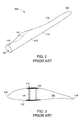
- FIG. 2 is a detailed view of a wind turbine blade 106.
- the blade 106 includes an upper shell member 110 and a lower shell member 112.
- the upper shell member 110 may be configured as the suction side surface of the blade 106
- the lower shell member 112 may be configured as the pressure side surface of the blade 106.
- These shell members 110 and 112 are typically fabricated from layers of woven fabric and resin.
- the blade 106 includes a leading edge 114 and a trailing edge 116, as well as a root portion 118, and a tip portion 120.
- the upper shell member 110, and the lower shell member 112 are joined together at the leading edge 114 and the trailing edge 116.
- the blade 106 includes an internal cavity 122 ( FIGS. 2 and 3 ) in which various structural members, such as spar caps and one or more shear webs, are configured.
- FIG. 3 is a cross-sectional view of a wind turbine blade 106 ( FIG. 2 ).
- the blade 106 includes one or more internal structural shear webs 124 that span between the upper shell member 110 and lower shell member 112 to form a structural support.
- the shear web 124 spans between spar caps 125 that are configured on internal surfaces of the shell members 110 and 112.
- the shear webs 124 and the spar caps 125 extend at least along a longitudinal length of the blade 106, and are typically, but not necessarily, configured as I-shaped members.
- a longitudinal length of the blade 106 is the distance between the root portion 118 and the tip portion 120 ( FIG.2 ), at the opposite ends of the blade 106.
- the spar caps 125 are usually fixed to an internal surface of the shell member or placed in the shell member.
- the spar caps typically comprises of an assemblage of layers of unidirectional (UD) composite fiber.
- the cross-sections at any section along the length of the spar cap 125 are often rectangular.
- the fabrication of each of these constituent parts involves a labor-intensive process that includes for instance, laying out fabric, glass fibers, and/or foam, followed by or with intervening resin application steps.
- a contact length of a shear web with a bonding material provided between the shear web and a spar cap is referred to as a bond width (BW).
- the bond width of the shear web may be a measure of the surface area of the shear web bonded to or in contact with the bonding material.
- a "bond thickness" of a shear web with a spar cap refers to a gap between a portion of the shear web (that is in contact with a bonding material) and a portion of the spar cap, which is usually occupied by the bonding material to join/bond the two portions.
- the shear web 124 is joined to the spar caps 125 using a bonding material, such as an adhesive or a bond paste.
- a bonding material such as an adhesive or a bond paste.
- the length dimension of the shear web should be sufficient to span between the spar caps, and the thickness dimension (i.e., width) should be enough to provide enough surface area (which can be assessed by measuring a bond width BW) to securely bond with the bond paste.
- these production processes involve various testing steps, for example to measure the required bond thickness to determine the required amount of the bond paste, and to ensure minimum required bond width, especially in inaccessible sections of the blade (for example, from about 20 meters from the root portion to the tip portion of a blade). These measurements usually require closing and opening the blade (i.e., joining the upper shell 110 and the lower shell 112) at least once.
- At least one shell member, the lower shell member 110 or the upper shell member 112, or both members include an improved spar cap 130 ( FIG. 4 ) according to some embodiments of the present invention as described in greater detail below.
- the present invention also encompasses various method embodiments for assembling the shear web 124 to the improved spar caps 130 within the wind turbine blade.
- FIG. 4 depicts an enlarged cross-sectional illustration of a portion of a shell member 110 having an improved spar cap 130 bonded to a shear web 124.
- the spar caps 130 may be integrated with the shell members 110.
- the spar caps 130 may be positioned inside of the internal and outer surfaces of the shell member 110, or may form part of the shell member 110.
- the spar cap 130 includes a cavity structure 140 configured on a surface 132 of the spar cap 130.
- the cavity structure 140 includes two parallel side walls 142 and 144 extending away from the surface 132.
- the side walls 142 and 144 may be about 0.5 millimeters to about 3 millimeters thick.
- the cavity structure 140 includes a cavity 150 defined by the inner surfaces 146 and 148 of the side walls 142 and 144, and a bottom surface 147 between the extended side walls 142 and 144.
- the bottom surface 147 may be a portion of the surface 132 of the spar cap 130.
- the cavity structure 140 can extend fully or partially along the longitudinal length of the spar cap 130.
- the cavity structure 140 can also be understood to include a longitudinal cavity 150 e.g., a grove.
- the cross section of the cavity 150 may be cup-shaped with sharp or round corners.
- the cavity structure 140 can be manufactured during the infusion of the spar cap 130 or the shell member 110. Other techniques may be used as well.
- Various composite fibers may be used for the cavity structure 140 similar to the material used for spar caps.
- the cavity structure 140 is formed of a fiber reinforced plastic.
- the cavity structure 140 can be positioned substantially at the middle of the spar cap 130 to accept a shear web 124.
- the cavity 150 may be wide enough to accommodate the shear web 124, and may have a length to define a depth 'd' of the cavity 150.
- the cavity 150 may have a depth between about 50 millimeters and 150 millimeters, and a width between about 10 millimeters to about 100 millimeters.
- the shear web 124 may have a length or height '1' in the span wise direction and a width or thickness 'w.' In some instances, the width 'w' of the shear web 124 may vary along the longitudinal length of the blade 106 ( FIG. 2 ). In some of these instances, the width of the cavity 150 may also vary accordingly.
- the shear web 124 can be positioned in the cavity 150 to be joined with the cavity structure 140 of the spar cap 130. In some instances, the transverse end 128 of the shear web 124 is positioned within the cavity 150 so the side walls 142 and 144 of the cavity structure 140 extend along the longitudinal sides (shear web sides) 126 and 127 of the shear web 124.
- the cavity 150 contains a bonding material (for example, a bond paste) 152 to adhere the shear web 124.
- a bonding material for example, a bond paste
- the shear web 124 is positioned in the middle of the cavity 152, and substantially perpendicular to the bottom surface 147.
- the transverse end 128 and a portion (of height or length 'x') of each of the longitudinal sides 126 and 127 of the shear web 124 along the length '1' is immersed (or encased) into the bonding material 152.
- These portions of the longitudinal sides 126 and 127 of the shear web 124 immersed into the bonding material 152 may be referred to as "immersion thickness" of the shear web 124.
- the shear web 124 may not be perpendicular to the bottom surface 147, and have varying immersion thicknesses along the longitudinal side walls 126 and 127.
- a bond thickness between a portion of thickness 'x' of the longitudinal side walls 127 or 126 of the shear web 124 and the corresponding (or closest) side wall 144 or 142 of the cavity 150 is referred to as BT 1
- the bond thickness of the transverse end 128 of the shear web 124 and the bottom surface 147 of the cavity 150 is referred to as BT 2 , throughout the specification.
- the cavity 150 can be sized to have a width greater than the width (w) of the shear web 124, and provides a substantial bond thickness BT 1 .
- a substantial bond thickness BT 1 refers to at least about 5 percent of the width (w) of the shear web 124.
- a ratio of the width of the shear web (w) to the bond thickness BT 1 of the shear web 124 with the cavity side wall (142 or 144) may be between about 1:1 and about 15:1. In certain instances, the ratio may range between about 4:1 and about 14:1.
- the bond thickness BT 1 may provide a space to the bonding material to squeeze up/down while positioning the shear web 124 into the bonding material 152, and adjust (increase/decrease) the immersion thickness 'x' of the shear web 124, to achieve the required bond width (BW) of the shear web.
- the bond thickness BT 1 ranges between about 1 millimeter and about 10 millimeters.
- a cavity structure 140 is configured on a surface of the spar cap 130, having two parallel side walls 142 and 144 defining a cavity 150 (as explained previously), along the longitudinal length of the blade 106.
- a bonding material 152 is disposed within the cavity 150.
- the shear web 124 is then pushed into the bonding material 152 such that the transverse end 128 and a portion of the shear web 124 are immersed into the bonding material 152.
- the bonding material gets squeezed at BT 1 , and rises up along the longitudinal side walls of the shear web 124.
- the immersion thickness 'x' of the shear web 124 increases as the transverse end 128 of the shear web 124 moves inside the bonding material 152.
- the shear web 124 can be pushed in the bonding material 152 until predetermined values of the bond thickness BT 2 , and /or the bond width (BW) is attained to achieve high bond strength.
- the method further includes steps of positioning the shear web 124 in the cavity 150 such that a ratio of the width of the shear web (w) to the bond thickness BT 1 may be between about 1:1 and about 15:1. In certain instances, the ratio may range between about 4:1 and about 14:1.
- the method may further include providing the bonding material 152 in the cavity 150 in a measured amount and compressing the shear web 124 into the bonding material 152 until a required BW is achieved.
- a predetermined amount of the bonding material may help in preventing or reducing squeeze-out of the boding material from the cavity 150 during the assembly of the shear web 124 with the cavity structure 140 of the spar cap, while maintaining the required BW and bond thickness BT 2 .
- the cavity 150 contains at least about 50 percent of the bonding material by volume of the cavity.
- the volume of the cavity 150 refers to a volume occupied between the parallel side walls 142 and 144 of depth 'd' and the bottom surface 147.
- the amount of the bonding material may range between about 70 percent and about 90 percent, by volume of the cavity.
- the bond width (BW) of the shear web 124 with the bonding material 152 ranges from about 20 millimeters to about 200 millimeters.
- the bond thickness BT 2 may be up to about 30 millimeters. In some embodiments, the bond thickness BT 2 ranges from about 1 millimeter to about 30 millimeters.
- the above described design of the spar caps, and their bond configuration with the shear web accommodate large variance in the bond thickness BT 2 and the bond width (BW), which improves strength and tolerance of the bond between the shear web and spar caps.
- the present designs may result in shear stress instead of peel stress and, moreover, uniformly distributed bond stress, which improves the reliability of the bond.
- the aspects of the present invention allow adjusting the bond thickness BT 2 and the bond width BW by changing the immersion thickness of the shear web.
- the bond width BW is not dependent on the thickness of the shear web, and can be adjusted to achieve sufficient surface area required to have a secure bond of high bond strength.
- the bond thickness BT 2 can accommodate any length deviations of the shear web, and can be adjusted to provide largest possible tolerance.
- the aspects of the present invention further enable to use cost effective shear webs.
- FIGS. 5-8 show several exemplary embodiments including some additional design features.
- the cavity side walls 142 and 144 may be extended further from the top end of the U shape cavity 150.
- FIGS. 5-7 show the extended portions 160, 162. These portions may be helpful in preventing any squeeze out of the bonding material 152. These designs also help to align the shear web 124 in the center of the cavity 150 if misaligned.
- the side walls may be extended in a 'V' shape as depicted in FIG.5 . In some other instances, these portions may be shaped rounded as shown in FIG. 6 .
- a support can be provided to shear web.
- FIG. a support can be provided to shear web.
- FIG. 7 depicts extension of the side walls of the cavity in such a way to support the shear web 124.
- the extended portions may also act as distance holder that can hold the shear web in the center of the cavity.
- FIG. 5 shows some embodiments that include integrated distance holders 170 introduced at specific locations around the shear web 125 within the gap (bond thickness BT1) between the shear web and the sidewalls of the cavity.
- the present invention also encompasses any configuration of a wind turbine 100 ( FIG. 1 ) wherein at least one of the blades 106 includes the spar caps and the shear web assembly configuration as discussed above.
- Embodiments of the present invention provide advantages to leverage a relatively inexpensive, simple, and rapid process to assemble and join a shear web with the spar caps while manufacturing a wind turbine blade, as compared to currently available methods.
- the resulting joint/bond may have high strength and reliability due, in part, to improved bond thickness and bond width.
- an additional advantage is the ability to assemble the shear web without several testing steps, and thus to manufacture the blade in simpler steps, as compared to known multi-step, cumbersome manufacturing processes.
- the aspects of the present invention simplify the assembly process of shear webs, and improve the reliability and tolerance of the shear web-spar caps bond.
Landscapes
- Engineering & Computer Science (AREA)
- Life Sciences & Earth Sciences (AREA)
- Sustainable Development (AREA)
- Sustainable Energy (AREA)
- Chemical & Material Sciences (AREA)
- Combustion & Propulsion (AREA)
- Mechanical Engineering (AREA)
- General Engineering & Computer Science (AREA)
- Wind Motors (AREA)
Abstract
Description
- The invention relates generally to wind turbine blades. More particularly, the invention relates to spar caps, and their assembly configuration with shear webs within the wind turbine blades, and methods for assembling shear webs in the wind turbine blades.
- Turbine blades are the primary elements of wind turbines for converting kinetic energy in wind into electrical energy. The blades have the cross-sectional profile of an airfoil such that, during operation, air flows over the blade producing a pressure difference between the sides. Consequently, a lift force, which is directed from a pressure side towards a suction side, acts on the blade. The lift force generates torque on the main rotor shaft, which is geared to a generator for producing electricity.
- The turbine blades typically consist of a suction side shell and a pressure side shell that are bonded together at bond lines along the trailing and leading edges of the blade. An internal shear web extends between the pressure and suction side shell members, and is bonded to spar caps affixed to the inner faces of the shell members. The shear web should have sufficient dimensions (for example, width) to provide enough surface area to securely bond, by a bond paste for example. Furthermore, relatively exact length dimensions are required for the shear web to span between the spar caps and achieve a bond between the spar caps and the transverse ends of the shear web. Achieving these dimensions, as well as an adequate bond, can be difficult, and forming the juncture between the spar caps and shear web is a time-consuming and tedious process that often requires significant re-work.
- Accordingly, it would be desirable to have an improved bond configuration between a shear web and spar caps that addresses one or more of the deficiencies of certain conventional configurations.
- One embodiment of the invention is directed to a wind turbine blade. The blade includes an upper shell member having a spar cap disposed on an internal surface of the upper shell, and a lower shell member having a spar cap disposed on an internal surface of the lower shell. The spar cap of the upper shell member, the spar cap of the lower shell member or both the spar caps include at least one cavity structure along a longitudinal length of the blade. A shear web extends between the spar caps along the longitudinal length of the blade, with a transverse end of the shear web positioned in a cavity of the at least one cavity structure, wherein a ratio of a width of the shear web to a bond thickness of the shear web with a side wall of the cavity structure is between about 1:1 and about 15:1.
- Another embodiment of the invention is directed to a method of assembling a shear web in a wind turbine blade. The method includes manufacturing a spar cap including at least one cavity structure disposed on an internal surface of an upper shell member, an internal surface of a lower shell member, or both the shell members, along a longitudinal length of a blade, disposing a bonding material within a cavity of the at least one cavity structure, and positioning a transverse end of a shear web in the bonding material within the cavity such as a ratio of a width of the shear web to a bond thickness of the shear web with a side wall of the cavity structure is between about 1:1 and about 15:1.
- Various features and aspects of the present invention will become better understood when the following detailed description is read with reference to the accompanying drawings in which like characters represent like parts throughout the drawings.
-
FIG. 1 is a prospective view of a conventional wind turbine; -
FIG. 2 is a perspective view of a conventional wind turbine blade; -
FIG. 3 is a cross-sectional view of a conventional wind turbine blade; -
FIG. 4 is an enlarged cross-sectional view of an assembly of a spar cap and a shear web, in accordance with an embodiment of the invention; -
FIG. 5 is an enlarged cross-sectional view of an assembly of a spar cap and a shear web, in accordance with another embodiment of the invention; -
FIG. 6 is an enlarged cross-sectional view of an assembly of a spar cap and a shear web, in accordance with yet another embodiment of the invention; and -
FIG. 7 is an enlarged cross-sectional view of an assembly of a spar cap and a shear web, in accordance with yet another embodiment of the invention. - Approximating language, as used herein throughout the specification and claims, may be applied to modify any quantitative representation that could permissibly vary, without resulting in a change in the basic function to which it is related. Accordingly, a value modified by a term or terms, such as "about," is not limited to the precise value specified. In some instances, the approximating language may correspond to the precision of an instrument for measuring the value.
- In the following specification and claims, the singular forms "a", "an" and "the" include plural referents unless the context clearly dictates otherwise. As used herein, the terms "may" and "may be" indicate a possibility of an occurrence within a set of circumstances; a possession of a specified property, characteristic or function; and/or qualify another verb by expressing one or more of an ability, capability, or possibility associated with the qualified verb. Accordingly, usage of "may" and "may be" indicates that a modified term is apparently appropriate, capable, or suitable for an indicated capacity, function, or usage, while taking into account that in some circumstances, the modified term may sometimes not be appropriate, capable, or suitable.
- The terms "comprising," "including," and "having" are intended to be inclusive, and mean that there may be additional elements other than the listed elements. As used herein, the term "and/or" includes any and all combinations of one or more of the associated listed items.
-
FIGS. 1-3 are provided for illustrative purposes only to place the present invention in an exemplary field of use. It should be appreciated that the invention is not limited to any particular type of wind turbine configuration. -
FIG. 1 illustrates awind turbine 100 of conventional construction. Thewind turbine 100 includes atower 102 with anacelle 104 mounted thereon. A plurality ofturbine blades 106 are mounted to arotor hub 108, which is in turn connected to a main flange that turns a main rotor shaft. The wind turbine power generation and control components are housed within thenacelle 104. -
FIG. 2 is a detailed view of awind turbine blade 106. Theblade 106 includes anupper shell member 110 and alower shell member 112. Theupper shell member 110 may be configured as the suction side surface of theblade 106, while thelower shell member 112 may be configured as the pressure side surface of theblade 106. Theseshell members blade 106 includes a leadingedge 114 and atrailing edge 116, as well as aroot portion 118, and atip portion 120. As is well known in the art, theupper shell member 110, and thelower shell member 112 are joined together at the leadingedge 114 and thetrailing edge 116. Theblade 106 includes an internal cavity 122 (FIGS. 2 and 3 ) in which various structural members, such as spar caps and one or more shear webs, are configured. -
FIG. 3 is a cross-sectional view of a wind turbine blade 106 (FIG. 2 ). Theblade 106 includes one or more internalstructural shear webs 124 that span between theupper shell member 110 andlower shell member 112 to form a structural support. In particular, theshear web 124 spans betweenspar caps 125 that are configured on internal surfaces of theshell members shear webs 124 and thespar caps 125 extend at least along a longitudinal length of theblade 106, and are typically, but not necessarily, configured as I-shaped members. A longitudinal length of theblade 106 is the distance between theroot portion 118 and the tip portion 120 (FIG.2 ), at the opposite ends of theblade 106. - The
spar caps 125 are usually fixed to an internal surface of the shell member or placed in the shell member. The spar caps typically comprises of an assemblage of layers of unidirectional (UD) composite fiber. The cross-sections at any section along the length of thespar cap 125 are often rectangular. The fabrication of each of these constituent parts (for example, shell members, spar caps) involves a labor-intensive process that includes for instance, laying out fabric, glass fibers, and/or foam, followed by or with intervening resin application steps. - As used herein, a contact length of a shear web with a bonding material provided between the shear web and a spar cap is referred to as a bond width (BW). The bond width of the shear web may be a measure of the surface area of the shear web bonded to or in contact with the bonding material. A "bond thickness" of a shear web with a spar cap refers to a gap between a portion of the shear web (that is in contact with a bonding material) and a portion of the spar cap, which is usually occupied by the bonding material to join/bond the two portions.
- With typical blade construction, the
shear web 124 is joined to thespar caps 125 using a bonding material, such as an adhesive or a bond paste. As discussed previously, the length dimension of the shear web should be sufficient to span between the spar caps, and the thickness dimension (i.e., width) should be enough to provide enough surface area (which can be assessed by measuring a bond width BW) to securely bond with the bond paste. - Various designs have been proposed to achieve a desired bond width between the spar caps and the shear web, for example using a shear web with a laminate or c-flange, use of a rigid flange etc. These configurations, however, do not accommodate relatively large length variances (e.g., shortages) in the shear web, and often result in break off and blade "rattling" during operation of the wind turbine. In addition, air voids, unpredictable misalignment, peel-off, and squeeze-out of the bond paste, and insufficient bond width in the typical production processes, can result in areas of decreased bond strength, which is particularly problematic in inaccessible sections of the blade where repair is not possible. Moreover, these production processes involve various testing steps, for example to measure the required bond thickness to determine the required amount of the bond paste, and to ensure minimum required bond width, especially in inaccessible sections of the blade (for example, from about 20 meters from the root portion to the tip portion of a blade). These measurements usually require closing and opening the blade (i.e., joining the
upper shell 110 and the lower shell 112) at least once. - Various aspects of the invention described herein address the noted shortcomings of the state of the art. Referring to
FIG. 3 again, at least one shell member, thelower shell member 110 or theupper shell member 112, or both members include an improved spar cap 130 (FIG. 4 ) according to some embodiments of the present invention as described in greater detail below. The present invention also encompasses various method embodiments for assembling theshear web 124 to the improved spar caps 130 within the wind turbine blade. -
FIG. 4 depicts an enlarged cross-sectional illustration of a portion of ashell member 110 having animproved spar cap 130 bonded to ashear web 124. In some embodiments, the spar caps 130 may be integrated with theshell members 110. For example, the spar caps 130 may be positioned inside of the internal and outer surfaces of theshell member 110, or may form part of theshell member 110. Thespar cap 130 includes acavity structure 140 configured on asurface 132 of thespar cap 130. Thecavity structure 140 includes twoparallel side walls surface 132. Theside walls cavity structure 140 includes acavity 150 defined by theinner surfaces side walls bottom surface 147 between theextended side walls bottom surface 147 may be a portion of thesurface 132 of thespar cap 130. - The
cavity structure 140 can extend fully or partially along the longitudinal length of thespar cap 130. Thecavity structure 140 can also be understood to include alongitudinal cavity 150 e.g., a grove. The cross section of thecavity 150 may be cup-shaped with sharp or round corners. During construction of the blade, thecavity structure 140 can be manufactured during the infusion of thespar cap 130 or theshell member 110. Other techniques may be used as well. Various composite fibers may be used for thecavity structure 140 similar to the material used for spar caps. In one embodiment, thecavity structure 140 is formed of a fiber reinforced plastic. - The
cavity structure 140 can be positioned substantially at the middle of thespar cap 130 to accept ashear web 124. Thecavity 150 may be wide enough to accommodate theshear web 124, and may have a length to define a depth 'd' of thecavity 150. In some embodiments, thecavity 150 may have a depth between about 50 millimeters and 150 millimeters, and a width between about 10 millimeters to about 100 millimeters. - The
shear web 124 may have a length or height '1' in the span wise direction and a width or thickness 'w.' In some instances, the width 'w' of theshear web 124 may vary along the longitudinal length of the blade 106 (FIG. 2 ). In some of these instances, the width of thecavity 150 may also vary accordingly. Theshear web 124 can be positioned in thecavity 150 to be joined with thecavity structure 140 of thespar cap 130. In some instances, thetransverse end 128 of theshear web 124 is positioned within thecavity 150 so theside walls cavity structure 140 extend along the longitudinal sides (shear web sides) 126 and 127 of theshear web 124. Thecavity 150 contains a bonding material (for example, a bond paste) 152 to adhere theshear web 124. In the illustrated embodiments ofFIGS. 4-7 , theshear web 124 is positioned in the middle of thecavity 152, and substantially perpendicular to thebottom surface 147. In these instances, thetransverse end 128 and a portion (of height or length 'x') of each of thelongitudinal sides shear web 124 along the length '1' is immersed (or encased) into thebonding material 152. These portions of thelongitudinal sides shear web 124 immersed into thebonding material 152 may be referred to as "immersion thickness" of theshear web 124. In some other embodiments, theshear web 124 may not be perpendicular to thebottom surface 147, and have varying immersion thicknesses along thelongitudinal side walls - Referring to
FIG. 4 , the bond width (BW) of the shear web is equal to the addition of the width (w) of theshear web 124 and the immersion thicknesses of the shearweb side walls 
- A bond thickness between a portion of thickness 'x' of the
longitudinal side walls shear web 124 and the corresponding (or closest)side wall cavity 150 is referred to as BT1, and the bond thickness of thetransverse end 128 of theshear web 124 and thebottom surface 147 of thecavity 150 is referred to as BT2, throughout the specification. - As described previously, the
cavity 150 can be sized to have a width greater than the width (w) of theshear web 124, and provides a substantial bond thickness BT1. As used herein, a substantial bond thickness BT1 refers to at least about 5 percent of the width (w) of theshear web 124. According to some embodiments of the invention, a ratio of the width of the shear web (w) to the bond thickness BT1 of theshear web 124 with the cavity side wall (142 or 144) may be between about 1:1 and about 15:1. In certain instances, the ratio may range between about 4:1 and about 14:1. The bond thickness BT1 may provide a space to the bonding material to squeeze up/down while positioning theshear web 124 into thebonding material 152, and adjust (increase/decrease) the immersion thickness 'x' of theshear web 124, to achieve the required bond width (BW) of the shear web. In one embodiment, the bond thickness BT1 ranges between about 1 millimeter and about 10 millimeters. - In a particular method embodiment, a
cavity structure 140 is configured on a surface of thespar cap 130, having twoparallel side walls blade 106. Abonding material 152 is disposed within thecavity 150. Theshear web 124 is then pushed into thebonding material 152 such that thetransverse end 128 and a portion of theshear web 124 are immersed into thebonding material 152. As theshear web 124 pushes into thebonding material 152, the bonding material gets squeezed at BT1, and rises up along the longitudinal side walls of theshear web 124. That means that the immersion thickness 'x' of theshear web 124 increases as thetransverse end 128 of theshear web 124 moves inside thebonding material 152. In some embodiments, theshear web 124 can be pushed in thebonding material 152 until predetermined values of the bond thickness BT2, and /or the bond width (BW) is attained to achieve high bond strength. The method further includes steps of positioning theshear web 124 in thecavity 150 such that a ratio of the width of the shear web (w) to the bond thickness BT1 may be between about 1:1 and about 15:1. In certain instances, the ratio may range between about 4:1 and about 14:1. - The method may further include providing the
bonding material 152 in thecavity 150 in a measured amount and compressing theshear web 124 into thebonding material 152 until a required BW is achieved. A predetermined amount of the bonding material may help in preventing or reducing squeeze-out of the boding material from thecavity 150 during the assembly of theshear web 124 with thecavity structure 140 of the spar cap, while maintaining the required BW and bond thickness BT2. In one embodiment, thecavity 150 contains at least about 50 percent of the bonding material by volume of the cavity. The volume of thecavity 150 refers to a volume occupied between theparallel side walls bottom surface 147. In some embodiments, the amount of the bonding material may range between about 70 percent and about 90 percent, by volume of the cavity. - In some embodiments, the bond width (BW) of the
shear web 124 with thebonding material 152 ranges from about 20 millimeters to about 200 millimeters. The bond thickness BT2 may be up to about 30 millimeters. In some embodiments, the bond thickness BT2 ranges from about 1 millimeter to about 30 millimeters. - The above described design of the spar caps, and their bond configuration with the shear web, accommodate large variance in the bond thickness BT2 and the bond width (BW), which improves strength and tolerance of the bond between the shear web and spar caps. Moreover, the present designs may result in shear stress instead of peel stress and, moreover, uniformly distributed bond stress, which improves the reliability of the bond.
- Unlike conventional designs and processes, the aspects of the present invention allow adjusting the bond thickness BT2 and the bond width BW by changing the immersion thickness of the shear web. The bond width BW is not dependent on the thickness of the shear web, and can be adjusted to achieve sufficient surface area required to have a secure bond of high bond strength. The bond thickness BT2 can accommodate any length deviations of the shear web, and can be adjusted to provide largest possible tolerance. In addition to several technological advantages, the aspects of the present invention further enable to use cost effective shear webs.
-
FIGS. 5-8 show several exemplary embodiments including some additional design features. In some embodiments, thecavity side walls U shape cavity 150.FIGS. 5-7 show theextended portions bonding material 152. These designs also help to align theshear web 124 in the center of thecavity 150 if misaligned. In some instances, the side walls may be extended in a 'V' shape as depicted inFIG.5 . In some other instances, these portions may be shaped rounded as shown inFIG. 6 . In some embodiments, a support can be provided to shear web.FIG. 7 depicts extension of the side walls of the cavity in such a way to support theshear web 124. The extended portions may also act as distance holder that can hold the shear web in the center of the cavity.FIG. 5 shows some embodiments that includeintegrated distance holders 170 introduced at specific locations around theshear web 125 within the gap (bond thickness BT1) between the shear web and the sidewalls of the cavity. - The shape and size of the several components discussed above with reference to
FIGS. 1-8 are only illustrative for the understanding of the blade structure, and design and geometry of various components, and are not meant to limit the scope of the invention. - The present invention also encompasses any configuration of a wind turbine 100 (
FIG. 1 ) wherein at least one of theblades 106 includes the spar caps and the shear web assembly configuration as discussed above. As it has been described in detail with respect to specific exemplary embodiments and methods thereof, it will be appreciated that those skilled in the art, upon attaining an understanding of the foregoing, may readily produce alterations to, variations of, and equivalents to such embodiments. Accordingly, the scope of the present disclosure is by way of example rather than by way of limitation, and the subject disclosure does not preclude inclusion of such modifications, variations and/or additions to the present subject matter as would be readily apparent to one of ordinary skill in the art. - Embodiments of the present invention provide advantages to leverage a relatively inexpensive, simple, and rapid process to assemble and join a shear web with the spar caps while manufacturing a wind turbine blade, as compared to currently available methods. The resulting joint/bond may have high strength and reliability due, in part, to improved bond thickness and bond width. Moreover, an additional advantage is the ability to assemble the shear web without several testing steps, and thus to manufacture the blade in simpler steps, as compared to known multi-step, cumbersome manufacturing processes. In brief, the aspects of the present invention simplify the assembly process of shear webs, and improve the reliability and tolerance of the shear web-spar caps bond.
- While only certain features of the invention have been illustrated and described herein, many modifications and changes will occur to those skilled in the art. It is, therefore, to be understood that the appended claims are intended to cover all such modifications and changes as fall within the true spirit of the invention. Furthermore, all of the patents, patent applications, articles, and texts which are mentioned above are incorporated herein by reference.
Claims (15)
- A wind turbine blade (106), comprising:an upper shell member (110) having a spar cap (130) disposed on an internal surface of the upper shell,a lower shell member having a spar cap disposed on an internal surface of the lower shell,wherein the spar cap (130) of the upper shell member (110), the spar cap of the lower shell member or both the spar caps comprise at least one cavity structure (140) along a longitudinal length of the blade, andat least one shear web (124) extending between the spar caps (130) along the longitudinal length of the blade, with a transverse end of the shear web (124) positioned in the at least one cavity structure (140), wherein a ratio of a width of the shear web (124) to a bond thickness of a longitudinal side of the shear web (124) with a side wall of the cavity structure (140) is between about 1:1 and about 15:1.
- The wind turbine blade (106) of claim 1, wherein the at least one cavity structure (140) comprises a cup-shaped cavity having a bottom wall between the side walls extending away from the spar cap (130) so as to extend along the longitudinal sides of the shear web (124).
- The wind turbine blade (106) of any preceding claim, wherein the cavity (140) has a depth from about 50 millimeters to about 150 millimeters.
- The wind turbine blade (106) of any preceding claim, wherein the cavity (140) has a width in a range from about 10 millimeters to about 100 millimeters.
- The wind turbine blade (106) of any preceding claim, wherein the spar cap (130) of the upper shell (110), the spar cap of the lower shell, or both the spar caps comprise an unidirectional composite material.
- The wind turbine blade (106) of any preceding claim, wherein the at least one cavity structure (140) comprises fiber-reinforced plastic.
- The wind turbine blade (106) of any preceding claim, wherein the cavity structure (140) comprises a bonding material disposed in the cavity.
- The wind turbine blade (106) of claim 7, wherein the cavity (140) comprises at least about 50 percent bonding material, by total volume of the cavity.
- The wind turbine blade (106) of any preceding claim, wherein the transverse end and a portion of the longitudinal side of the shear web (124) are encased in a bonding material.
- The wind turbine blade (106) of any preceding claim, wherein the transverse end of the shear web (124) forms a bond with a bottom wall of a cavity (150), and the portion of the longitudinal side of the shear web (124) forms a bond with a side wall of a cavity structure (140) through the bonding material.
- The wind turbine blade (106) of any preceding claim, wherein a bond thickness of the transverse end of the shear web (124) to the bottom wall of the cavity is up to about 30 millimeters.
- The wind turbine blade (106) of any preceding claim, wherein a bond thickness of the portion of the longitudinal side of the shear web (124) to the side wall of the cavity structure is in a range from about 1 millimeter to about 10 millimeters.
- The wind turbine blade (106) of any preceding claim, wherein a bond width of the shear web (124) with the bonding material is in a range from about 20 millimeters to about 200 millimeters.
- The wind turbine blade (106) of any preceding claim, wherein the ratio of the width of the shear web (124) to the bond thickness of the longitudinal side of the shear web with the side wall of the cavity structure is between about 4:1 and about 14:1.
- A method for assembling a shear web (124) in a wind turbine blade (106), comprising:manufacturing a spar cap (130) comprising at least one cavity structure (140) disposed on an internal surface of an upper shell member (110), an internal surface of a lower shell member, or both the shell members, along a longitudinal length of a blade,disposing a bonding material within a cavity (150) of the at least one cavity structure (140),positioning a transverse end of a shear web (124) in the cavity (150), wherein a ratio of a width of the shear web (124) to a bond thickness of a longitudinal side of the shear web (124) with a sidewall of the cavity structure (140) is between about 1:1 and about 15:1.
Applications Claiming Priority (1)
| Application Number | Priority Date | Filing Date | Title |
|---|---|---|---|
| US14/094,079 US20150152838A1 (en) | 2013-12-02 | 2013-12-02 | Spar caps-shear web assembly configuration for wind turbine blades, and methods thereof |
Publications (2)
| Publication Number | Publication Date |
|---|---|
| EP2878807A1 true EP2878807A1 (en) | 2015-06-03 |
| EP2878807B1 EP2878807B1 (en) | 2023-04-12 |
Family
ID=51900303
Family Applications (1)
| Application Number | Title | Priority Date | Filing Date |
|---|---|---|---|
| EP14193435.6A Active EP2878807B1 (en) | 2013-12-02 | 2014-11-17 | Spar caps-shear web assembly configuration for wind turbine blades, and methods thereof |
Country Status (2)
| Country | Link |
|---|---|
| US (1) | US20150152838A1 (en) |
| EP (1) | EP2878807B1 (en) |
Cited By (4)
| Publication number | Priority date | Publication date | Assignee | Title |
|---|---|---|---|---|
| WO2017088890A1 (en) * | 2015-11-26 | 2017-06-01 | Vestas Wind Systems A/S | Improvements relating to the manufacture of wind turbine blades |
| EP3501665A1 (en) * | 2017-12-19 | 2019-06-26 | Nordex Energy GmbH | System and method for producing a rotor blade |
| CN113007042A (en) * | 2019-12-20 | 2021-06-22 | 江苏金风科技有限公司 | Blade repairing method of wind generating set, blade cementing structure and blade |
| US11448182B2 (en) | 2017-04-05 | 2022-09-20 | Vestas Wind Systems A/S | Relating to wind turbine blade manufacture |
Families Citing this family (11)
| Publication number | Priority date | Publication date | Assignee | Title |
|---|---|---|---|---|
| WO2013086667A1 (en) * | 2011-12-12 | 2013-06-20 | General Electric Company | Wind turbine blade shear web connection assembly |
| EP2927481B1 (en) * | 2014-03-31 | 2021-09-22 | Siemens Gamesa Renewable Energy A/S | Rotor blade for a wind turbine |
| DK3329118T3 (en) | 2015-07-28 | 2019-10-07 | Vestas Wind Sys As | IMPROVEMENTS IN THE WINDOW EXPERIENCE |
| DK201570491A1 (en) * | 2015-07-28 | 2016-08-01 | Vestas Wind Sys As | Improvements relating to wind turbine blades |
| US10422315B2 (en) * | 2015-09-01 | 2019-09-24 | General Electric Company | Pultruded components for a shear web of a wind turbine rotor blade |
| WO2017220596A1 (en) * | 2016-06-22 | 2017-12-28 | Lm Wind Power International Technology Ii Aps | Wind turbine blade with improved glue joints and related method |
| US10828843B2 (en) | 2017-03-16 | 2020-11-10 | General Electric Company | Shear webs for wind turbine rotor blades and methods for manufacturing same |
| JP6993542B2 (en) | 2018-09-11 | 2022-02-04 | ティーピーアイ コンポジッツ,インコーポレーティッド | Alignment profile for pultrusion of wind blade spur caps |
| US11840038B2 (en) * | 2018-12-03 | 2023-12-12 | Vestas Wind Systems A/S | Wind turbine blade manufacture |
| CN115596601B (en) * | 2021-06-28 | 2025-03-25 | 江苏金风科技有限公司 | Blade, method for manufacturing blade and wind turbine generator set |
| CN119195970A (en) * | 2024-08-13 | 2024-12-27 | 远景能源有限公司 | A modular thermoplastic web structure for wind power, a manufacturing method thereof, and a wind power blade |
Citations (4)
| Publication number | Priority date | Publication date | Assignee | Title |
|---|---|---|---|---|
| US5476704A (en) * | 1992-07-01 | 1995-12-19 | Hoac-Austria Flugzeugwerk Wr.Neustadt Gesellschaft M.B.H. | Plastic-composite profiled girder, in particular a wing spar for aircraft and for wind-turbine rotors |
| US20110008175A1 (en) * | 2009-07-07 | 2011-01-13 | Nordex Energy Gmbh | Rotor blade for a wind turbine and method for its production |
| WO2013086667A1 (en) * | 2011-12-12 | 2013-06-20 | General Electric Company | Wind turbine blade shear web connection assembly |
| EP2843227A1 (en) * | 2013-08-28 | 2015-03-04 | General Electric Company | Method for installing a shear web insert within a segmented rotor blade assembly |
Family Cites Families (7)
| Publication number | Priority date | Publication date | Assignee | Title |
|---|---|---|---|---|
| US8272618B2 (en) * | 2004-11-30 | 2012-09-25 | The Boeing Company | Minimum bond thickness assembly feature assurance |
| US7393488B2 (en) * | 2005-05-25 | 2008-07-01 | The Boeing Company | Methods of joining structures and joints formed thereby |
| US9016551B2 (en) * | 2006-11-02 | 2015-04-28 | The Boeing Company | Method and apparatus to construct metal securement member for an aircraft |
| US7810757B2 (en) * | 2006-11-02 | 2010-10-12 | The Boeing Company | Mounting device for an aircraft |
| US7712993B2 (en) * | 2007-11-30 | 2010-05-11 | The Boeing Company | Double shear joint for bonding in structural applications |
| US8262362B2 (en) * | 2011-06-08 | 2012-09-11 | General Electric Company | Wind turbine blade shear web with spring flanges |
| US8393871B2 (en) * | 2011-07-19 | 2013-03-12 | General Electric Company | Wind turbine blade shear web connection assembly |
-
2013
- 2013-12-02 US US14/094,079 patent/US20150152838A1/en not_active Abandoned
-
2014
- 2014-11-17 EP EP14193435.6A patent/EP2878807B1/en active Active
Patent Citations (4)
| Publication number | Priority date | Publication date | Assignee | Title |
|---|---|---|---|---|
| US5476704A (en) * | 1992-07-01 | 1995-12-19 | Hoac-Austria Flugzeugwerk Wr.Neustadt Gesellschaft M.B.H. | Plastic-composite profiled girder, in particular a wing spar for aircraft and for wind-turbine rotors |
| US20110008175A1 (en) * | 2009-07-07 | 2011-01-13 | Nordex Energy Gmbh | Rotor blade for a wind turbine and method for its production |
| WO2013086667A1 (en) * | 2011-12-12 | 2013-06-20 | General Electric Company | Wind turbine blade shear web connection assembly |
| EP2843227A1 (en) * | 2013-08-28 | 2015-03-04 | General Electric Company | Method for installing a shear web insert within a segmented rotor blade assembly |
Non-Patent Citations (2)
| Title |
|---|
| GINGER GARDINER: "Wind blades: Pi preforms increase shear web failure load : CompositesWorld", 1 October 2013 (2013-10-01), XP055180385, Retrieved from the Internet <URL:http://www.compositesworld.com/articles/wind-blades-pi-preforms-increase-shear-web-failure-load-> [retrieved on 20150331] * |
| GINGER GARDINER: "Wind blades: Pi preforms increase shear web failure load : CompositesWorld", 1 October 2013 (2013-10-01), XP055180394, Retrieved from the Internet <URL:http://www.compositesworld.com/articles/wind-blades-pi-preforms-increase-shear-web-failure-load-> [retrieved on 20150331] * |
Cited By (6)
| Publication number | Priority date | Publication date | Assignee | Title |
|---|---|---|---|---|
| WO2017088890A1 (en) * | 2015-11-26 | 2017-06-01 | Vestas Wind Systems A/S | Improvements relating to the manufacture of wind turbine blades |
| US10920744B2 (en) | 2015-11-26 | 2021-02-16 | Vestas Wind Systems A/S | Manufacture of wind turbine blades |
| US11448182B2 (en) | 2017-04-05 | 2022-09-20 | Vestas Wind Systems A/S | Relating to wind turbine blade manufacture |
| EP3501665A1 (en) * | 2017-12-19 | 2019-06-26 | Nordex Energy GmbH | System and method for producing a rotor blade |
| CN113007042A (en) * | 2019-12-20 | 2021-06-22 | 江苏金风科技有限公司 | Blade repairing method of wind generating set, blade cementing structure and blade |
| CN113007042B (en) * | 2019-12-20 | 2022-07-15 | 江苏金风科技有限公司 | Blade repairing method of wind generating set, blade cementing structure and blade |
Also Published As
| Publication number | Publication date |
|---|---|
| US20150152838A1 (en) | 2015-06-04 |
| EP2878807B1 (en) | 2023-04-12 |
Similar Documents
| Publication | Publication Date | Title |
|---|---|---|
| EP2878807B1 (en) | Spar caps-shear web assembly configuration for wind turbine blades, and methods thereof | |
| CN102817771B (en) | Wind turbine blade and the method that shear web is assembled to spar flange | |
| CN102889170B (en) | Wind turbine blade shear web connection part | |
| US8393871B2 (en) | Wind turbine blade shear web connection assembly | |
| US8257048B2 (en) | Wind turbine blade multi-component shear web with intermediate connection assembly | |
| US10422315B2 (en) | Pultruded components for a shear web of a wind turbine rotor blade | |
| EP3418556A1 (en) | A wind turbine blade with hybrid spar cap and associated method for making | |
| EP2402594A1 (en) | Wind turbine blade for a rotor of a wind turbine | |
| EP3015703B1 (en) | System and method for controlling bonding material in a wind turbine blade | |
| EP3011170B1 (en) | A tribrid wind turbine blade | |
| US10648451B2 (en) | Method for manufacturing a rotor blade of a wind power plant, rotor blade and wind power plant | |
| US9702339B2 (en) | Wind turbine blades with cap-assisted bond configuration and associated bonding method | |
| US20180238301A1 (en) | Shear Web for a Wind Turbine Rotor Blade | |
| WO2009153344A1 (en) | An assembly tool for a spar for a wind turbine | |
| EP3568587B1 (en) | Wind turbine blade, wind turbine and method for producing a wind turbine blade | |
| EP3788253B1 (en) | Shear web for a wind turbine rotor blade | |
| CN112840120A (en) | Wind turbine blade with multiple spar caps | |
| US20220178347A1 (en) | Wind turbine blade and method for producing a wind turbine blade | |
| US20240352917A1 (en) | Segmented wind turbine blade | |
| BR112017025470B1 (en) | WIND TURBINE BLADE WITH A TRAILING EDGE SPACE SECTION |
Legal Events
| Date | Code | Title | Description |
|---|---|---|---|
| PUAI | Public reference made under article 153(3) epc to a published international application that has entered the european phase |
Free format text: ORIGINAL CODE: 0009012 |
|
| 17P | Request for examination filed |
Effective date: 20141117 |
|
| AK | Designated contracting states |
Kind code of ref document: A1 Designated state(s): AL AT BE BG CH CY CZ DE DK EE ES FI FR GB GR HR HU IE IS IT LI LT LU LV MC MK MT NL NO PL PT RO RS SE SI SK SM TR |
|
| AX | Request for extension of the european patent |
Extension state: BA ME |
|
| R17P | Request for examination filed (corrected) |
Effective date: 20151203 |
|
| RBV | Designated contracting states (corrected) |
Designated state(s): AL AT BE BG CH CY CZ DE DK EE ES FI FR GB GR HR HU IE IS IT LI LT LU LV MC MK MT NL NO PL PT RO RS SE SI SK SM TR |
|
| STAA | Information on the status of an ep patent application or granted ep patent |
Free format text: STATUS: EXAMINATION IS IN PROGRESS |
|
| 17Q | First examination report despatched |
Effective date: 20161216 |
|
| RIC1 | Information provided on ipc code assigned before grant |
Ipc: B29C 65/48 20060101ALI20220823BHEP Ipc: B29C 65/00 20060101ALI20220823BHEP Ipc: F03D 1/06 20060101AFI20220823BHEP |
|
| GRAP | Despatch of communication of intention to grant a patent |
Free format text: ORIGINAL CODE: EPIDOSNIGR1 |
|
| STAA | Information on the status of an ep patent application or granted ep patent |
Free format text: STATUS: GRANT OF PATENT IS INTENDED |
|
| INTG | Intention to grant announced |
Effective date: 20221117 |
|
| GRAS | Grant fee paid |
Free format text: ORIGINAL CODE: EPIDOSNIGR3 |
|
| GRAA | (expected) grant |
Free format text: ORIGINAL CODE: 0009210 |
|
| STAA | Information on the status of an ep patent application or granted ep patent |
Free format text: STATUS: THE PATENT HAS BEEN GRANTED |
|
| AK | Designated contracting states |
Kind code of ref document: B1 Designated state(s): AL AT BE BG CH CY CZ DE DK EE ES FI FR GB GR HR HU IE IS IT LI LT LU LV MC MK MT NL NO PL PT RO RS SE SI SK SM TR |
|
| REG | Reference to a national code |
Ref country code: GB Ref legal event code: FG4D |
|
| REG | Reference to a national code |
Ref country code: CH Ref legal event code: EP |
|
| REG | Reference to a national code |
Ref country code: DE Ref legal event code: R096 Ref document number: 602014086667 Country of ref document: DE |
|
| REG | Reference to a national code |
Ref country code: IE Ref legal event code: FG4D |
|
| REG | Reference to a national code |
Ref country code: AT Ref legal event code: REF Ref document number: 1559917 Country of ref document: AT Kind code of ref document: T Effective date: 20230515 |
|
| P01 | Opt-out of the competence of the unified patent court (upc) registered |
Effective date: 20230522 |
|
| REG | Reference to a national code |
Ref country code: LT Ref legal event code: MG9D |
|
| REG | Reference to a national code |
Ref country code: NL Ref legal event code: MP Effective date: 20230412 |
|
| REG | Reference to a national code |
Ref country code: AT Ref legal event code: MK05 Ref document number: 1559917 Country of ref document: AT Kind code of ref document: T Effective date: 20230412 |
|
| PG25 | Lapsed in a contracting state [announced via postgrant information from national office to epo] |
Ref country code: NL Free format text: LAPSE BECAUSE OF FAILURE TO SUBMIT A TRANSLATION OF THE DESCRIPTION OR TO PAY THE FEE WITHIN THE PRESCRIBED TIME-LIMIT Effective date: 20230412 |
|
| PG25 | Lapsed in a contracting state [announced via postgrant information from national office to epo] |
Ref country code: SE Free format text: LAPSE BECAUSE OF FAILURE TO SUBMIT A TRANSLATION OF THE DESCRIPTION OR TO PAY THE FEE WITHIN THE PRESCRIBED TIME-LIMIT Effective date: 20230412 Ref country code: PT Free format text: LAPSE BECAUSE OF FAILURE TO SUBMIT A TRANSLATION OF THE DESCRIPTION OR TO PAY THE FEE WITHIN THE PRESCRIBED TIME-LIMIT Effective date: 20230814 Ref country code: NO Free format text: LAPSE BECAUSE OF FAILURE TO SUBMIT A TRANSLATION OF THE DESCRIPTION OR TO PAY THE FEE WITHIN THE PRESCRIBED TIME-LIMIT Effective date: 20230712 Ref country code: ES Free format text: LAPSE BECAUSE OF FAILURE TO SUBMIT A TRANSLATION OF THE DESCRIPTION OR TO PAY THE FEE WITHIN THE PRESCRIBED TIME-LIMIT Effective date: 20230412 Ref country code: AT Free format text: LAPSE BECAUSE OF FAILURE TO SUBMIT A TRANSLATION OF THE DESCRIPTION OR TO PAY THE FEE WITHIN THE PRESCRIBED TIME-LIMIT Effective date: 20230412 |
|
| PG25 | Lapsed in a contracting state [announced via postgrant information from national office to epo] |
Ref country code: RS Free format text: LAPSE BECAUSE OF FAILURE TO SUBMIT A TRANSLATION OF THE DESCRIPTION OR TO PAY THE FEE WITHIN THE PRESCRIBED TIME-LIMIT Effective date: 20230412 Ref country code: PL Free format text: LAPSE BECAUSE OF FAILURE TO SUBMIT A TRANSLATION OF THE DESCRIPTION OR TO PAY THE FEE WITHIN THE PRESCRIBED TIME-LIMIT Effective date: 20230412 Ref country code: LV Free format text: LAPSE BECAUSE OF FAILURE TO SUBMIT A TRANSLATION OF THE DESCRIPTION OR TO PAY THE FEE WITHIN THE PRESCRIBED TIME-LIMIT Effective date: 20230412 Ref country code: LT Free format text: LAPSE BECAUSE OF FAILURE TO SUBMIT A TRANSLATION OF THE DESCRIPTION OR TO PAY THE FEE WITHIN THE PRESCRIBED TIME-LIMIT Effective date: 20230412 Ref country code: IS Free format text: LAPSE BECAUSE OF FAILURE TO SUBMIT A TRANSLATION OF THE DESCRIPTION OR TO PAY THE FEE WITHIN THE PRESCRIBED TIME-LIMIT Effective date: 20230812 Ref country code: HR Free format text: LAPSE BECAUSE OF FAILURE TO SUBMIT A TRANSLATION OF THE DESCRIPTION OR TO PAY THE FEE WITHIN THE PRESCRIBED TIME-LIMIT Effective date: 20230412 Ref country code: GR Free format text: LAPSE BECAUSE OF FAILURE TO SUBMIT A TRANSLATION OF THE DESCRIPTION OR TO PAY THE FEE WITHIN THE PRESCRIBED TIME-LIMIT Effective date: 20230713 Ref country code: AL Free format text: LAPSE BECAUSE OF FAILURE TO SUBMIT A TRANSLATION OF THE DESCRIPTION OR TO PAY THE FEE WITHIN THE PRESCRIBED TIME-LIMIT Effective date: 20230412 |
|
| RAP2 | Party data changed (patent owner data changed or rights of a patent transferred) |
Owner name: LM WIND POWER A/S |
|
| REG | Reference to a national code |
Ref country code: GB Ref legal event code: 732E Free format text: REGISTERED BETWEEN 20231123 AND 20231129 |
|
| PG25 | Lapsed in a contracting state [announced via postgrant information from national office to epo] |
Ref country code: FI Free format text: LAPSE BECAUSE OF FAILURE TO SUBMIT A TRANSLATION OF THE DESCRIPTION OR TO PAY THE FEE WITHIN THE PRESCRIBED TIME-LIMIT Effective date: 20230412 |
|
| REG | Reference to a national code |
Ref country code: DE Ref legal event code: R081 Ref document number: 602014086667 Country of ref document: DE Owner name: GENERAL ELECTRIC RENOVABLES ESPANA S.L., ES Free format text: FORMER OWNER: GENERAL ELECTRIC CO., SCHENECTADY, NY, US Ref country code: DE Ref legal event code: R097 Ref document number: 602014086667 Country of ref document: DE Ref country code: DE Ref legal event code: R081 Ref document number: 602014086667 Country of ref document: DE Owner name: LM WIND POWER A/S, DK Free format text: FORMER OWNER: GENERAL ELECTRIC CO., SCHENECTADY, NY, US |
|
| PG25 | Lapsed in a contracting state [announced via postgrant information from national office to epo] |
Ref country code: SK Free format text: LAPSE BECAUSE OF FAILURE TO SUBMIT A TRANSLATION OF THE DESCRIPTION OR TO PAY THE FEE WITHIN THE PRESCRIBED TIME-LIMIT Effective date: 20230412 |
|
| PG25 | Lapsed in a contracting state [announced via postgrant information from national office to epo] |
Ref country code: SM Free format text: LAPSE BECAUSE OF FAILURE TO SUBMIT A TRANSLATION OF THE DESCRIPTION OR TO PAY THE FEE WITHIN THE PRESCRIBED TIME-LIMIT Effective date: 20230412 Ref country code: SK Free format text: LAPSE BECAUSE OF FAILURE TO SUBMIT A TRANSLATION OF THE DESCRIPTION OR TO PAY THE FEE WITHIN THE PRESCRIBED TIME-LIMIT Effective date: 20230412 Ref country code: RO Free format text: LAPSE BECAUSE OF FAILURE TO SUBMIT A TRANSLATION OF THE DESCRIPTION OR TO PAY THE FEE WITHIN THE PRESCRIBED TIME-LIMIT Effective date: 20230412 Ref country code: EE Free format text: LAPSE BECAUSE OF FAILURE TO SUBMIT A TRANSLATION OF THE DESCRIPTION OR TO PAY THE FEE WITHIN THE PRESCRIBED TIME-LIMIT Effective date: 20230412 Ref country code: DK Free format text: LAPSE BECAUSE OF FAILURE TO SUBMIT A TRANSLATION OF THE DESCRIPTION OR TO PAY THE FEE WITHIN THE PRESCRIBED TIME-LIMIT Effective date: 20230412 Ref country code: CZ Free format text: LAPSE BECAUSE OF FAILURE TO SUBMIT A TRANSLATION OF THE DESCRIPTION OR TO PAY THE FEE WITHIN THE PRESCRIBED TIME-LIMIT Effective date: 20230412 |
|
| PLBE | No opposition filed within time limit |
Free format text: ORIGINAL CODE: 0009261 |
|
| STAA | Information on the status of an ep patent application or granted ep patent |
Free format text: STATUS: NO OPPOSITION FILED WITHIN TIME LIMIT |
|
| 26N | No opposition filed |
Effective date: 20240115 |
|
| PG25 | Lapsed in a contracting state [announced via postgrant information from national office to epo] |
Ref country code: SI Free format text: LAPSE BECAUSE OF FAILURE TO SUBMIT A TRANSLATION OF THE DESCRIPTION OR TO PAY THE FEE WITHIN THE PRESCRIBED TIME-LIMIT Effective date: 20230412 |
|
| PG25 | Lapsed in a contracting state [announced via postgrant information from national office to epo] |
Ref country code: SI Free format text: LAPSE BECAUSE OF FAILURE TO SUBMIT A TRANSLATION OF THE DESCRIPTION OR TO PAY THE FEE WITHIN THE PRESCRIBED TIME-LIMIT Effective date: 20230412 Ref country code: IT Free format text: LAPSE BECAUSE OF FAILURE TO SUBMIT A TRANSLATION OF THE DESCRIPTION OR TO PAY THE FEE WITHIN THE PRESCRIBED TIME-LIMIT Effective date: 20230412 |
|
| REG | Reference to a national code |
Ref country code: CH Ref legal event code: PL |
|
| PG25 | Lapsed in a contracting state [announced via postgrant information from national office to epo] |
Ref country code: MC Free format text: LAPSE BECAUSE OF FAILURE TO SUBMIT A TRANSLATION OF THE DESCRIPTION OR TO PAY THE FEE WITHIN THE PRESCRIBED TIME-LIMIT Effective date: 20230412 |
|
| PG25 | Lapsed in a contracting state [announced via postgrant information from national office to epo] |
Ref country code: LU Free format text: LAPSE BECAUSE OF NON-PAYMENT OF DUE FEES Effective date: 20231117 |
|
| PG25 | Lapsed in a contracting state [announced via postgrant information from national office to epo] |
Ref country code: CH Free format text: LAPSE BECAUSE OF NON-PAYMENT OF DUE FEES Effective date: 20231130 |
|
| PG25 | Lapsed in a contracting state [announced via postgrant information from national office to epo] |
Ref country code: MC Free format text: LAPSE BECAUSE OF FAILURE TO SUBMIT A TRANSLATION OF THE DESCRIPTION OR TO PAY THE FEE WITHIN THE PRESCRIBED TIME-LIMIT Effective date: 20230412 Ref country code: LU Free format text: LAPSE BECAUSE OF NON-PAYMENT OF DUE FEES Effective date: 20231117 Ref country code: CH Free format text: LAPSE BECAUSE OF NON-PAYMENT OF DUE FEES Effective date: 20231130 |
|
| REG | Reference to a national code |
Ref country code: BE Ref legal event code: MM Effective date: 20231130 |
|
| REG | Reference to a national code |
Ref country code: IE Ref legal event code: MM4A |
|
| PG25 | Lapsed in a contracting state [announced via postgrant information from national office to epo] |
Ref country code: IE Free format text: LAPSE BECAUSE OF NON-PAYMENT OF DUE FEES Effective date: 20231117 |
|
| PG25 | Lapsed in a contracting state [announced via postgrant information from national office to epo] |
Ref country code: BE Free format text: LAPSE BECAUSE OF NON-PAYMENT OF DUE FEES Effective date: 20231130 |
|
| REG | Reference to a national code |
Ref country code: DE Ref legal event code: R081 Ref document number: 602014086667 Country of ref document: DE Owner name: GENERAL ELECTRIC RENOVABLES ESPANA S.L., ES Free format text: FORMER OWNER: LM WIND POWER A/S, KOLDING, DK |
|
| REG | Reference to a national code |
Ref country code: GB Ref legal event code: 732E Free format text: REGISTERED BETWEEN 20241003 AND 20241009 |
|
| PG25 | Lapsed in a contracting state [announced via postgrant information from national office to epo] |
Ref country code: IE Free format text: LAPSE BECAUSE OF NON-PAYMENT OF DUE FEES Effective date: 20231117 Ref country code: BE Free format text: LAPSE BECAUSE OF NON-PAYMENT OF DUE FEES Effective date: 20231130 |
|
| PG25 | Lapsed in a contracting state [announced via postgrant information from national office to epo] |
Ref country code: BG Free format text: LAPSE BECAUSE OF FAILURE TO SUBMIT A TRANSLATION OF THE DESCRIPTION OR TO PAY THE FEE WITHIN THE PRESCRIBED TIME-LIMIT Effective date: 20230412 |
|
| PG25 | Lapsed in a contracting state [announced via postgrant information from national office to epo] |
Ref country code: BG Free format text: LAPSE BECAUSE OF FAILURE TO SUBMIT A TRANSLATION OF THE DESCRIPTION OR TO PAY THE FEE WITHIN THE PRESCRIBED TIME-LIMIT Effective date: 20230412 |
|
| PG25 | Lapsed in a contracting state [announced via postgrant information from national office to epo] |
Ref country code: CY Free format text: LAPSE BECAUSE OF FAILURE TO SUBMIT A TRANSLATION OF THE DESCRIPTION OR TO PAY THE FEE WITHIN THE PRESCRIBED TIME-LIMIT; INVALID AB INITIO Effective date: 20141117 |
|
| PG25 | Lapsed in a contracting state [announced via postgrant information from national office to epo] |
Ref country code: HU Free format text: LAPSE BECAUSE OF FAILURE TO SUBMIT A TRANSLATION OF THE DESCRIPTION OR TO PAY THE FEE WITHIN THE PRESCRIBED TIME-LIMIT; INVALID AB INITIO Effective date: 20141117 |
|
| PG25 | Lapsed in a contracting state [announced via postgrant information from national office to epo] |
Ref country code: TR Free format text: LAPSE BECAUSE OF FAILURE TO SUBMIT A TRANSLATION OF THE DESCRIPTION OR TO PAY THE FEE WITHIN THE PRESCRIBED TIME-LIMIT Effective date: 20230412 |
|
| PGFP | Annual fee paid to national office [announced via postgrant information from national office to epo] |
Ref country code: DE Payment date: 20251022 Year of fee payment: 12 |
|
| PGFP | Annual fee paid to national office [announced via postgrant information from national office to epo] |
Ref country code: GB Payment date: 20251023 Year of fee payment: 12 |
|
| PGFP | Annual fee paid to national office [announced via postgrant information from national office to epo] |
Ref country code: FR Payment date: 20251023 Year of fee payment: 12 |