EP2878572A1 - Electric forklift, steering control system used for the same and method for controlling electric forklift - Google Patents
Electric forklift, steering control system used for the same and method for controlling electric forklift Download PDFInfo
- Publication number
- EP2878572A1 EP2878572A1 EP14194748.1A EP14194748A EP2878572A1 EP 2878572 A1 EP2878572 A1 EP 2878572A1 EP 14194748 A EP14194748 A EP 14194748A EP 2878572 A1 EP2878572 A1 EP 2878572A1
- Authority
- EP
- European Patent Office
- Prior art keywords
- brushless
- motor
- steering wheel
- acceleration
- signal
- Prior art date
- Legal status (The legal status is an assumption and is not a legal conclusion. Google has not performed a legal analysis and makes no representation as to the accuracy of the status listed.)
- Granted
Links
Images


Classifications
-
- B—PERFORMING OPERATIONS; TRANSPORTING
- B66—HOISTING; LIFTING; HAULING
- B66F—HOISTING, LIFTING, HAULING OR PUSHING, NOT OTHERWISE PROVIDED FOR, e.g. DEVICES WHICH APPLY A LIFTING OR PUSHING FORCE DIRECTLY TO THE SURFACE OF A LOAD
- B66F9/00—Devices for lifting or lowering bulky or heavy goods for loading or unloading purposes
- B66F9/06—Devices for lifting or lowering bulky or heavy goods for loading or unloading purposes movable, with their loads, on wheels or the like, e.g. fork-lift trucks
- B66F9/075—Constructional features or details
- B66F9/07568—Steering arrangements
-
- B—PERFORMING OPERATIONS; TRANSPORTING
- B62—LAND VEHICLES FOR TRAVELLING OTHERWISE THAN ON RAILS
- B62D—MOTOR VEHICLES; TRAILERS
- B62D5/00—Power-assisted or power-driven steering
- B62D5/04—Power-assisted or power-driven steering electrical, e.g. using an electric servo-motor connected to, or forming part of, the steering gear
- B62D5/0457—Power-assisted or power-driven steering electrical, e.g. using an electric servo-motor connected to, or forming part of, the steering gear characterised by control features of the drive means as such
- B62D5/046—Controlling the motor
-
- B—PERFORMING OPERATIONS; TRANSPORTING
- B62—LAND VEHICLES FOR TRAVELLING OTHERWISE THAN ON RAILS
- B62D—MOTOR VEHICLES; TRAILERS
- B62D6/00—Arrangements for automatically controlling steering depending on driving conditions sensed and responded to, e.g. control circuits
Definitions
- Embodiments of the present disclosure generally relate to a vehicle technology field, and more particularly, to a steering control system used for an electric forklift, an electric forklift and a method for controlling an electric forklift.
- an electric power steering system of an electric forklift mainly adopts a brush DC motor, which dramatically increases a maintenance cost and results in a low efficiency.
- a brushless DC motor also may be used in the electric forklift.
- it is generally required to perform an idle speed control if the electric power steering system adopts the brushless DC motor, and thus a real-time response cannot be implemented during a steering of the electric forklift and it is hard to satisfy a high power requirement of the electric forklift. Therefore, it is necessary to improve the electric power steering system of the electric forklift.
- Embodiments of the present disclosure seek to solve at least one of the problems existing in the related art to at least some extent.
- an objective of the present disclosure is to provide a steering control system used for an electric forklift, which can make a real-time response to a steering request of the electric forklift, decrease power consumption of the electric forklift, improve a steering efficiency and save a maintenance cost.
- Another objective of the present disclosure is to provide an electric forklift.
- Yet another objective of the present disclosure is to provide a method for controlling an electric forklift.
- a steering control system used for an electric forklift includes a brushless DC motor; a steering wheel encoder, configured to detect a rotating speed signal and a direction signal of a steering wheel of the electric forklift; a power driver, connected with the brushless DC motor and configured to drive the brushless DC motor; a sampler, connected with the brushless DC motor and configured to sample an operation of the brushless DC motor to generate a sampling signal; and a controller, connected with the steering wheel encoder, the power driver and the sampler respectively and configured to generate a PWM control signal according to the rotating speed signal and the direction signal of the steering wheel, the sampling signal and a predetermined control strategy, and to send the PWM control signal to the power driver to control the brushless DC motor via the power driver.
- the controller can generate the PWM control signal according to the rotating speed signal and the direction signal of the steering wheel, the sampling signal and the predetermined control strategy, and then send the PWM control signal to the power driver to control the brushless DC motor via the power driver, therefore, the real-time response to the steering request of the electric forklift can be made and a hand feeling of rotating the steering wheel can be ensured, moreover, the power consumption of the electric forklift can be decreased, the steering efficiency can be improved and the maintenance cost can be saved.
- the predetermined control strategy includes: controlling the brushless DC motor to start if the controller determines that the steering wheel is rotated, wherein the controller determines whether the steering wheel is rotated according to the rotating speed signal and the direction signal of the steering wheel and the sampling signal; controlling the brushless DC motor to operate at a first acceleration if a starting time of the brushless DC motor is less than a first predetermined threshold; controlling the brushless DC motor to operate at a second acceleration if the starting time of the brushless DC motor is larger than the first predetermined threshold and less than a second predetermined threshold, in which the second acceleration is less than the first acceleration; controlling the brushless DC motor to operate at a third acceleration if the controller determines that the steering wheel is still in operation and the starting time of the brushless DC motor is larger than the second predetermined threshold and less than a third predetermined threshold, in which the third acceleration is less than the first acceleration and larger than the second acceleration. Therefore, a hardware drive pressure is relieved by using a segmented speed rise strategy so as to implement a zero
- the steering control system further includes a CAN communication interface, configured to be used by the controller to communicate with a vehicle control unit of the electric forklift.
- the steering control system further includes a UART interface, configured to be used by the controller to communicate with an upper computer.
- the steering control system further includes a memory module, configured to record an operation of the controller.
- the steering control system further includes a protection module, configured to perform an overvoltage and/or overcurrent protection on the steering control system.
- the power driver includes a first phase driving unit, a second phase driving unit and a third phase driving unit, each of the first to third phase driving units having N-level drivers, in which N is a positive integer. Therefore, the power driver can withstand a driving current instantly increased due to a real-time response mode adopted herein, and thus the corresponding real-time response can be made.
- an electric forklift includes a steering control system used for an electric forklift according to the first aspect of the present disclosure.
- a real-time response can be made to a steering request of the electric forklift and a hand feeling of rotating the steering wheel can be ensured; moreover, a power consumption of the electric forklift can be decreased, a steering efficiency can be improved and a maintenance cost can be saved.
- a method for controlling an electric forklift in which the electric forklift comprises a brushless DC motor and a steering wheel and the method includes steps of: detecting a rotating speed signal and a direction signal of the steering wheel; obtaining a sampling signal of an operation of the brushless DC motor; generating a PWM control signal according to the rotating speed signal and the direction signal of the steering wheel, the sampling signal and a predetermined control strategy; and controlling the brushless DC motor according to the PWM control signal to control the electric forklift.
- the sampling signal and the predetermined control strategy to control the brushless DC motor, therefore, real-time response to the steering request of the electric forklift can be made and a hand feeling of rotating the steering wheel can be ensured, moreover, the power consumption of the electric forklift can be decreased, the steering efficiency can be improved and the maintenance cost can be saved.
- the predetermined control strategy includes: controlling the brushless DC motor to start if the steering wheel is rotated, wherein whether the steering wheel is rotated is determined according to the rotating speed signal and the direction signal of the steering wheel and the sampling signal; controlling the brushless DC motor to operate at a first acceleration if a starting time of the brushless DC motor is less than a first predetermined threshold; and controlling the brushless DC motor to operate at a second acceleration if the starting time of the brushless DC motor is larger than the first predetermined threshold and less than a second predetermined threshold, in which the second acceleration is less than the first acceleration.
- the predetermined control strategy further includes: controlling the brushless DC motor to operate at a third acceleration if the steering wheel is still in operation and the starting time of the brushless DC motor is larger than the second predetermined threshold and less than a third predetermined threshold, in which the third acceleration is less than the first acceleration and larger than the second acceleration.
- Fig. 1 is a block diagram of a steering control system used for an electric forklift according to an embodiment of the present disclosure.
- the steering control system used for an electric forklift includes a brushless DC motor 1, a steering wheel encoder 2, a power driver 3, a sampler 4 and a controller 5.
- the steering wheel encoder 2 is configured to detect a rotating speed signal and a direction signal of a steering wheel of the electric forklift.
- the power driver 3 is connected with the brushless DC motor 1 and is configured to drive the brushless DC motor 1.
- the sampler 4 is connected with the brushless DC motor 1 and is configured to sample an operation of the brushless DC motor 1 to generate a sampling signal.
- the controller 5 is connected with the steering wheel encoder 2, the power driver 3 and the sampler 4 respectively and is configured to generate a PWM (pulse width modulation) control signal according to the rotating speed signal and the direction signal of the steering wheel, the sampling signal and a predetermined control strategy, and to send the PWM control signal to the power driver 3 to control the brushless DC motor 1 via the power driver 3.
- PWM pulse width modulation
- the steering wheel encoder 2 sends the detected rotating speed signal and the detected direction signal of the steering wheel of the electric forklift to the controller 5 such as a MCU (Micro Control Unit) to be processed.
- the MCU controls the brushless DC motor 1 to start according the signal from the steering wheel encoder 2 and generates the PWM control signal to drive the brushless DC motor 1 to operate via the power driver 3.
- the sampler 4 feeds the sampling signal back to the MCU, and the MCU generates the corresponding PWM control signal according to the predetermined control strategy so as to adjust a rising speed of the brushless DC motor 1.
- Fig. 2 is a schematic diagram showing an operation of a predetermined control strategy in a steering control system used for an electric forklift according to an embodiment of the present disclosure.
- the predetermined control strategy includes: controlling the brushless DC motor 1 to start if the controller 5 determines that the steering wheel is rotated, in which the controller 5 determines whether the steering wheel is rotated according to the rotating speed signal and the direction signal of the steering wheel and the sampling signal, then if a starting time of the brushless DC motor 1 is less than a first predetermined threshold t 1 (such as 1), controlling the brushless DC motor 1 to operate at a first acceleration a 1 ; if the starting time of the brushless DC motor 1 is larger the first predetermined threshold t 1 (such as 1) and less than a second predetermined threshold t 2 (such as 6), controlling the brushless DC motor 1 to operate at a second acceleration a 2 , in which the second acceleration a 2 is less than the first acceleration a 1 ; if the controller 5 determines that the steering wheel is still in operation and the starting time of the brushless DC motor 1 is larger than the second predetermined threshold a 2 (such as 6) and less than a third predetermined threshold
- the predetermined control strategy according to embodiments of the present disclosure has various adaptations, and the above embodiment of the present disclosure is just a preferable embodiment and shall not be used to limit the present disclosure. Moreover, any modification based on an idea of the predetermined control strategy according to embodiments of the present disclosure shall be fallen into a protection scope of the present disclosure.
- a hardware drive pressure is relieved by using a segmented speed rise strategy, i.e., presetting a plurality of speed levels, and the controller 5 controls a rise of a speed of the brushless DC motor 1 according to the feedback speed of the brushless DC motor 1 from the sampler 4 so as to implement a zero-speed start and ensure the hand feeling of rotating the steering wheel.
- a segmented speed rise strategy i.e., presetting a plurality of speed levels
- Fig. 3 is a schematic diagram of a steering control system used for an electric forklift according to another embodiment of the present disclosure.
- the steering control system used for an electric forklift further includes a CAN (Controller Area Network) communication interface 6.
- the controller 5 communicates with a vehicle control unit of the electric forklift via the CAN communication interface 6.
- the CAN communication interface 6 is connected with a CANH terminal and a CANL terminal of the controller 5.
- the steering control system used for an electric forklift further includes a UART (universal asynchronous receiver/transmitter) interface 7.
- the controller 5 communicates with an upper computer via the UART interface 7.
- the UART interface 5 is connected with a RX terminal and a TX terminal of the controller 5.
- the steering control system used for an electric forklift further includes a memory module 8.
- the memory module 8 is configured to record an operation of the controller 5.
- the steering control system used for an electric forklift further includes a protection module 9.
- the protection module 9 is configured to perform an overvoltage and/or overcurrent protection on the steering control system.
- the steering control system used for an electric forklift further includes a power source module (not shown in Fig. X).
- the power source module is configured to perform a voltage reduction process so as to supply power to the controller 5.
- the power driver 3 includes a first phase driving unit 31, a second phase driving unit 32 and a third phase driving unit 33.
- Each of the first phase driving unit 31, the second driving unit 32 and the third phase driving unit 33 may include N-level drivers, in which N is a positive integer.
- an input terminal of the first phase driving unit 31 is connected with a PWM3 terminal and a PWM4 terminal of the controller 5, and an output terminal of the first phase driving unit 31 is connected with a W phase of the brushless DC motor 1;
- an input terminal of the second phase driving unit 32 is connected with a PWM2 terminal and a PWM5 terminal of the controller 5, and an output terminal of the second phase driving unit 32 is connected with a V phase of the brushless DC motor 1;
- an input terminal of the third phase driving unit 33 is connected with a PWM1 terminal and a PWM6 terminal of the controller 5, and an output terminal of the third phase driving unit 33 is connected with a U phase of the brushless DC motor 1.
- Fig. 4 is a schematic circuit diagram of a first phase driving unit of a power driver in a steering control system used for an electric forklift according to an embodiment of the present disclosure.
- the first phase driving unit 31 includes a first level driver 311, a second level driver 312, a third level driver 313, a fourth level driver 314, a fifth level driver 315 and a sixth level driver 316.
- the first level driver 311, the second level driver 312 and the third level driver 313 are connected with each other in parallel and are connected between a first predetermined voltage +BATT and the W phase of the brushless DC motor 1;
- the fourth level driver 314, the fifth level driver 315 and the sixth level driver 316 are connected with each other in parallel and are connected between a second predetermined voltage -BATT and the W phase of the brushless DC motor 1.
- the first level driver 311 includes a first MOS transistor Q1, a first resistor R1 and a second resistor R2.
- a drain of the first MOS transistor Q1 is connected with the first predetermined voltage +BATT, and a source of the first MOS transistor Q1 is connected with the fourth level driver 314, and a gate of the first MOS transistor Q1 is connected with a first terminal of the first resistor R1, and a second terminal of the first resistor R1 is connected with a first terminal of the second resistor R2, and a second terminal of the second resistor R2 is connected with the W phase of the brushless DC motor 1.
- the second level driver 312 includes a second MOS transistor Q2, a third resistor R3 and a first capacitor C1.
- a drain of the second MOS transistor Q2 is connected with the first predetermined voltage +BATT, and a source of the second MOS transistor Q2 is connected with the fifth level driver 315, and a gate of the second transistor Q2 is connected with a first terminal of the third resistor R3, and a second terminal of the third resistor R3 is connected with a first terminal of the first capacitor C1 and a second terminal of the first capacitor C1 is connected with the W phase of the brushless DC motor 1.
- the third level driver 313 includes a third transistor Q3, a fourth resistor R4 and a second capacitor C2.
- a drain of the third transistor Q3 is connected with the first predetermined voltage +BATT, and a source of the third transistor Q3 is connected with the sixth level driver 316, and a gate of the third transistor Q3 is connected with a first terminal of the fourth resistor R4, and a second terminal of the fourth resistor R4 is connected with the PWM3 terminal of the controller 5, a first terminal of the second capacitor C2 is connected with the second terminal of the fourth resistor R4 and a second terminal of the second capacitor C2 is connected with the W phase of the brushless DC motor 1.
- the fourth level driver 314 includes a fourth transistor Q4, a fifth resistor R5 and a sixth resistor R6.
- a drain of the fourth transistor Q4 is connected with the source of the first transistor Q1, and a source of the fourth transistor Q4 is connected with the second predetermined voltage -BATT, and a gate of the fourth transistor Q4 is connected with a first terminal of the fifth resistor R5, and a second terminal of the fifth resistor R5 is connected with a first terminal of the sixth resistor R6 and a second terminal of the sixth resistor R6 is connected with the second predetermined voltage -BATT.
- the fifth level driver 315 includes a fifth transistor Q5, a seventh resistor R7 and a third capacitor C3.
- a drain of the fifth transistor Q5 is connected with the source of the second transistor Q2, and a source of the fifth transistor Q5 is connected with the second predetermined voltage -BATT, and a gate of the fifth transistor Q5 is connected with a first terminal of the seventh resistor R7, and a second terminal of the seventh resistor R7 is connected with a first terminal of the third capacitor C3 and a second terminal of the third capacitor C3 is connected with the second predetermined voltage -BATT.
- the sixth level driver 316 includes a sixth transistor Q6, an eighth resistor R8 and a fourth capacitor C4.
- a drain of the sixth transistor Q6 is connected with the source of the third transistor Q3, and a source of the sixth transistor Q6 is connected with the second predetermined voltage -BATT, and a gate of the sixth transistor Q6 is connected with a first terminal of the eighth resistor R8, and a second terminal of the eighth resistor R8 is connected with the PWM4 terminal of the controller 5, and a first terminal of the fourth capacitor C4 is connected with the second terminal of the eighth resistor R8 and a second terminal of the fourth capacitor C4 is connected with the second predetermined voltage -BATT.
- the second phase driving unit 32 and the third phase driving unit 33 can be implemented referring to the first phase driving unit 31. In this case, it is not described herein.
- the above embodiment is just a preferable example of the present disclosure and shall not be used to limit the present disclosure, and any modification based on an idea thereof shall be fallen into the protection scope of the present disclosure.
- any modification based on an idea thereof shall be fallen into the protection scope of the present disclosure.
- both a selection of the number of the MOS transistors and a modification of a connection mode of the MOS transistors shall be fallen into the protection scope of the present disclosure.
- the controller can generate the PWM control signal according to the rotating speed signal and the direction signal of the steering wheel, the sampling signal and the predetermined control strategy, and then send the PWM control signal to the power driver to control the brushless DC motor via the power driver, therefore, the real-time response to a steering request of the electric forklift can be made and a hand feeling of rotating the steering wheel can be ensured, moreover, a power consumption of the electric forklift can be decreased, a steering efficiency can be improved and a maintenance cost can be saved.
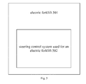
- Fig. 5 is block diagram of an electric forklift according to an embodiment of the present disclosure.
- the electric forklift 501 includes a steering control system 502 used for an electric forklift described in above embodiments of the present disclosure.
- a real-time response can be made to a steering request of the electric forklift and a hand feeling of rotating the steering wheel can be ensured; moreover, a power consumption of the electric forklift can be decreased, a steering efficiency can be improved and a maintenance cost can be saved.
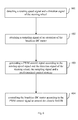
- Fig. 6 is a flow chart of a method for controlling an electric forklift according to an embodiment of the present disclosure.
- the method for controlling an electric forklift includes the following steps, in which the electric forklift includes a brushless DC motor and a steering wheel.
- step 601 a rotating speed signal and a direction signal of the steering wheel are detected.
- the rotating speed signal and the direction signal of a steering wheel can be detected by a steering wheel encoder, for example, the steering wheel encoder 2 shown in Fig. 1 .
- step 602 a sampling signal of an operation of the brushless DC motor is obtained.
- the sampling signal of an operation of the brushless DC motor is obtained by a sampler, for example, the sampler 4 shown in Fig. 1 .
- a PWM control signal according to the rotating speed signal and the direction signal of the steering wheel, the sampling signal and a predetermined control strategy is generated.
- the PWM control signal is generated by a controller, for example, the controller 5 shown in Fig. 1 .
- the predetermined control strategy includes: controlling the brushless DC motor to start if the steering wheel is rotated, wherein whether the steering wheel is rotated is determined according to the rotating speed signal and the direction signal of the steering wheel and the sampling signal; controlling the brushless DC motor to operate at a first acceleration if a starting time of the brushless DC motor is less than a first predetermined threshold; and controlling the brushless DC motor to operate at a second acceleration if the starting time of the brushless DC motor is larger than the first predetermined threshold and less than a second predetermined threshold, in which the second acceleration is less than the first acceleration.
- the predetermined control strategy further includes: controlling the brushless DC motor to operate at a third acceleration if the steering wheel is still in operation and the starting time of the brushless DC motor is larger than the second predetermined threshold and less than a third predetermined threshold, in which the third acceleration is less than the first acceleration and larger than the second acceleration.
- the predetermined control strategy according to embodiments of the present disclosure has various adaptations, and the above embodiment of the present disclosure is just a preferable embodiment and shall not be used to limit the present disclosure. Moreover, any modification based on an idea of the predetermined control strategy according to embodiments of the present disclosure shall be fallen into a protection scope of the present disclosure.
- a hardware drive pressure is relieved by using a segmented speed rise strategy, i.e., presetting a plurality of speed levels, and a rise of a speed of the brushless DC motor according to the feedback speed of the brushless DC motor so as to implement a zero-speed start and ensure the hand feeling of rotating the steering wheel.
- a segmented speed rise strategy i.e., presetting a plurality of speed levels, and a rise of a speed of the brushless DC motor according to the feedback speed of the brushless DC motor so as to implement a zero-speed start and ensure the hand feeling of rotating the steering wheel.
- the brushless DC motor is controlled according to the PWM control signal to control the electric forklift.
- the PWM control signal can be generated by the controller, and then the PWM control signal can be send to a power driver, for example, the power driver 3 shown in Fig. 1 , and then the power driver can drive the brushless DC motor according to the PWM control signal.
- the method for controlling an electric forklift further including: recording an operation state of the controller.
- the sampling signal and the predetermined control strategy to control the brushless DC motor, therefore, real-time response to the steering request of the electric forklift can be made and a hand feeling of rotating the steering wheel can be ensured, moreover, the power consumption of the electric forklift can be decreased, the steering efficiency can be improved and the maintenance cost can be saved.
- each part of the present disclosure may be realized by the hardware, software, firmware or their combination.
- a plurality of steps or methods may be realized by the software or firmware stored in the memory and executed by the appropriate instruction execution system.
- the steps or methods may be realized by one or a combination of the following techniques known in the art: a discrete logic circuit having a logic gate circuit for realizing a logic function of a data signal, an application-specific integrated circuit having an appropriate combination logic gate circuit, a programmable gate array (PGA), a field programmable gate array (FPGA), etc.
Landscapes
- Engineering & Computer Science (AREA)
- Transportation (AREA)
- Mechanical Engineering (AREA)
- Structural Engineering (AREA)
- Combustion & Propulsion (AREA)
- Chemical & Material Sciences (AREA)
- Civil Engineering (AREA)
- Life Sciences & Earth Sciences (AREA)
- Geology (AREA)
- Control Of Motors That Do Not Use Commutators (AREA)
- Steering Control In Accordance With Driving Conditions (AREA)
- Power Steering Mechanism (AREA)
- Forklifts And Lifting Vehicles (AREA)
Abstract
Description
- This application claims priority and benefits of Chinese Patent Application No.
201310629217.4 - Embodiments of the present disclosure generally relate to a vehicle technology field, and more particularly, to a steering control system used for an electric forklift, an electric forklift and a method for controlling an electric forklift.
- Currently, an electric power steering system of an electric forklift mainly adopts a brush DC motor, which dramatically increases a maintenance cost and results in a low efficiency.
- In related art, a brushless DC motor also may be used in the electric forklift. However, it is generally required to perform an idle speed control if the electric power steering system adopts the brushless DC motor, and thus a real-time response cannot be implemented during a steering of the electric forklift and it is hard to satisfy a high power requirement of the electric forklift. Therefore, it is necessary to improve the electric power steering system of the electric forklift.
- Embodiments of the present disclosure seek to solve at least one of the problems existing in the related art to at least some extent.
- Accordingly, an objective of the present disclosure is to provide a steering control system used for an electric forklift, which can make a real-time response to a steering request of the electric forklift, decrease power consumption of the electric forklift, improve a steering efficiency and save a maintenance cost.
- Another objective of the present disclosure is to provide an electric forklift.
- Yet another objective of the present disclosure is to provide a method for controlling an electric forklift.
- According to a first aspect of the present disclosure, a steering control system used for an electric forklift is provided. The steering control system includes a brushless DC motor; a steering wheel encoder, configured to detect a rotating speed signal and a direction signal of a steering wheel of the electric forklift; a power driver, connected with the brushless DC motor and configured to drive the brushless DC motor; a sampler, connected with the brushless DC motor and configured to sample an operation of the brushless DC motor to generate a sampling signal; and a controller, connected with the steering wheel encoder, the power driver and the sampler respectively and configured to generate a PWM control signal according to the rotating speed signal and the direction signal of the steering wheel, the sampling signal and a predetermined control strategy, and to send the PWM control signal to the power driver to control the brushless DC motor via the power driver.
- With the steering control system used for an electric forklift according to embodiments of the present disclosure, by detecting the rotating speed signal and the direction signal of the steering wheel of the electric forklift via the steering wheel encoder and sampling the operation of the brushless DC motor to generate the sampling signal via the sampler, the controller can generate the PWM control signal according to the rotating speed signal and the direction signal of the steering wheel, the sampling signal and the predetermined control strategy, and then send the PWM control signal to the power driver to control the brushless DC motor via the power driver, therefore, the real-time response to the steering request of the electric forklift can be made and a hand feeling of rotating the steering wheel can be ensured, moreover, the power consumption of the electric forklift can be decreased, the steering efficiency can be improved and the maintenance cost can be saved.
- In some embodiments, the predetermined control strategy includes: controlling the brushless DC motor to start if the controller determines that the steering wheel is rotated, wherein the controller determines whether the steering wheel is rotated according to the rotating speed signal and the direction signal of the steering wheel and the sampling signal; controlling the brushless DC motor to operate at a first acceleration if a starting time of the brushless DC motor is less than a first predetermined threshold; controlling the brushless DC motor to operate at a second acceleration if the starting time of the brushless DC motor is larger than the first predetermined threshold and less than a second predetermined threshold, in which the second acceleration is less than the first acceleration; controlling the brushless DC motor to operate at a third acceleration if the controller determines that the steering wheel is still in operation and the starting time of the brushless DC motor is larger than the second predetermined threshold and less than a third predetermined threshold, in which the third acceleration is less than the first acceleration and larger than the second acceleration. Therefore, a hardware drive pressure is relieved by using a segmented speed rise strategy so as to implement a zero-speed start, and the threshold is of a millisecond level, thus ensuring the hand feeling of rotating the steering wheel.
- In some embodiments, the steering control system further includes a CAN communication interface, configured to be used by the controller to communicate with a vehicle control unit of the electric forklift.
- In some embodiments, the steering control system further includes a UART interface, configured to be used by the controller to communicate with an upper computer.
- Therefore, a man-machine interaction can be achieved in the steering control system used for an electric forklift according to embodiments of the present disclosure.
- In some embodiments, the steering control system further includes a memory module, configured to record an operation of the controller.
- In some embodiments, the steering control system further includes a protection module, configured to perform an overvoltage and/or overcurrent protection on the steering control system.
- In some embodiments, the power driver includes a first phase driving unit, a second phase driving unit and a third phase driving unit, each of the first to third phase driving units having N-level drivers, in which N is a positive integer. Therefore, the power driver can withstand a driving current instantly increased due to a real-time response mode adopted herein, and thus the corresponding real-time response can be made.
- According to a second aspect of the present disclosure, an electric forklift is provided. The electric forklift includes a steering control system used for an electric forklift according to the first aspect of the present disclosure.
- With the electric forklift according to embodiments of the present disclosure, a real-time response can be made to a steering request of the electric forklift and a hand feeling of rotating the steering wheel can be ensured; moreover, a power consumption of the electric forklift can be decreased, a steering efficiency can be improved and a maintenance cost can be saved.
- According to a third aspect of the present disclosure, a method for controlling an electric forklift is provided, in which the electric forklift comprises a brushless DC motor and a steering wheel and the method includes steps of: detecting a rotating speed signal and a direction signal of the steering wheel; obtaining a sampling signal of an operation of the brushless DC motor; generating a PWM control signal according to the rotating speed signal and the direction signal of the steering wheel, the sampling signal and a predetermined control strategy; and controlling the brushless DC motor according to the PWM control signal to control the electric forklift.
- With the method for controlling an electric forklift according to embodiments of the present disclosure, by detecting the rotating speed signal and the direction signal of the steering wheel and sampling the operation of the brushless DC motor to generate the sampling signal, and generating the PWM control signal according to the rotating speed signal and the direction signal of the steering wheel, the sampling signal and the predetermined control strategy to control the brushless DC motor, therefore, real-time response to the steering request of the electric forklift can be made and a hand feeling of rotating the steering wheel can be ensured, moreover, the power consumption of the electric forklift can be decreased, the steering efficiency can be improved and the maintenance cost can be saved.
- In some embodiments, the predetermined control strategy includes: controlling the brushless DC motor to start if the steering wheel is rotated, wherein whether the steering wheel is rotated is determined according to the rotating speed signal and the direction signal of the steering wheel and the sampling signal; controlling the brushless DC motor to operate at a first acceleration if a starting time of the brushless DC motor is less than a first predetermined threshold; and controlling the brushless DC motor to operate at a second acceleration if the starting time of the brushless DC motor is larger than the first predetermined threshold and less than a second predetermined threshold, in which the second acceleration is less than the first acceleration.
- In some embodiments, the predetermined control strategy further includes: controlling the brushless DC motor to operate at a third acceleration if the steering wheel is still in operation and the starting time of the brushless DC motor is larger than the second predetermined threshold and less than a third predetermined threshold, in which the third acceleration is less than the first acceleration and larger than the second acceleration.
- Additional aspects and advantages of embodiments of present disclosure will be given in part in the following descriptions, become apparent in part from the following descriptions, or be learned from the practice of the embodiments of the present disclosure.
- These and other aspects and advantages of embodiments of the present disclosure will become apparent and more readily appreciated from the following descriptions made with reference to the accompanying drawings, in which:
-
Fig. 1 is a block diagram of a steering control system used for an electric forklift according to an embodiment of the present disclosure; -
Fig. 2 is a schematic diagram showing an operation of a predetermined control strategy in a steering control system used for an electric forklift according to an embodiment of the present disclosure; -
Fig. 3 is a schematic diagram of a steering control system used for an electric forklift according to another embodiment of the present disclosure; -
Fig. 4 is a schematic circuit diagram of a first phase driving unit of a power driver in a steering control system used for an electric forklift according to an embodiment of the present disclosure; -
Fig. 5 is a block diagram of an electric forklift according to an embodiment of the present disclosure; and -
Fig. 6 is a flow chart of a method for controlling an electric forklift according to an embodiment of the present disclosure. - Reference will be made in detail to embodiments of the present disclosure. Embodiments of the present disclosure will be shown in drawings, in which the same or similar elements and the elements having same or similar functions are denoted by like reference numerals throughout the descriptions. The embodiments described herein with reference to drawings are explanatory, illustrative, and used to generally understand the present disclosure. The embodiments shall not be construed to limit the present disclosure. Instead, the embodiments of the present disclosure include all the variants, modifications and their equivalents within the spirit and scope of the present disclosure as defined by the claims.
- It is to be understood that, in the description of the present disclosure, terms of "first" and "second" are only used for description and cannot be seen as indicating or implying relative importance. Unless otherwise stipulated and restricted, it is to be explained that terms of "linkage" and "connection" shall be understood broadly, for example, it could be mechanical connection or electrical connection; it could be direct linkage, indirect linkage via intermediate medium. Those skilled in the art shall understand the concrete notations of the terms mentioned above according to specific circumstances. Furthermore, unless otherwise explained, it is to be understood that a term of "a plurality of" refers to two or more.
- Any process or method described in a flow chart or described herein in other ways may be understood to include one or more modules, segments or portions of codes of executable instructions for achieving specific logical functions or steps in the process, and the scope of a preferred embodiment of the present disclosure includes other implementations, which should be understood by those skilled in the art.
- A steering control system used for an electric forklift, an electric forklift and a method for controlling an electric forklift will be described in the following with reference to drawings.
-
Fig. 1 is a block diagram of a steering control system used for an electric forklift according to an embodiment of the present disclosure. - As shown in
Fig. 1 , the steering control system used for an electric forklift includes abrushless DC motor 1, asteering wheel encoder 2, apower driver 3, asampler 4 and acontroller 5. Thesteering wheel encoder 2 is configured to detect a rotating speed signal and a direction signal of a steering wheel of the electric forklift. Thepower driver 3 is connected with thebrushless DC motor 1 and is configured to drive thebrushless DC motor 1. Thesampler 4 is connected with thebrushless DC motor 1 and is configured to sample an operation of thebrushless DC motor 1 to generate a sampling signal. - As shown in
Fig. 1 , thecontroller 5 is connected with thesteering wheel encoder 2, thepower driver 3 and thesampler 4 respectively and is configured to generate a PWM (pulse width modulation) control signal according to the rotating speed signal and the direction signal of the steering wheel, the sampling signal and a predetermined control strategy, and to send the PWM control signal to thepower driver 3 to control thebrushless DC motor 1 via thepower driver 3. - Specifically, the
steering wheel encoder 2 sends the detected rotating speed signal and the detected direction signal of the steering wheel of the electric forklift to thecontroller 5 such as a MCU (Micro Control Unit) to be processed. The MCU controls thebrushless DC motor 1 to start according the signal from thesteering wheel encoder 2 and generates the PWM control signal to drive thebrushless DC motor 1 to operate via thepower driver 3. In addition, thesampler 4 feeds the sampling signal back to the MCU, and the MCU generates the corresponding PWM control signal according to the predetermined control strategy so as to adjust a rising speed of thebrushless DC motor 1. -
Fig. 2 is a schematic diagram showing an operation of a predetermined control strategy in a steering control system used for an electric forklift according to an embodiment of the present disclosure. - As shown in
Fig. 2 , the predetermined control strategy includes: controlling thebrushless DC motor 1 to start if thecontroller 5 determines that the steering wheel is rotated, in which thecontroller 5 determines whether the steering wheel is rotated according to the rotating speed signal and the direction signal of the steering wheel and the sampling signal, then if a starting time of thebrushless DC motor 1 is less than a first predetermined threshold t1 (such as 1), controlling thebrushless DC motor 1 to operate at a first acceleration a1; if the starting time of thebrushless DC motor 1 is larger the first predetermined threshold t1 (such as 1) and less than a second predetermined threshold t2 (such as 6), controlling thebrushless DC motor 1 to operate at a second acceleration a2, in which the second acceleration a2 is less than the first acceleration a1; if thecontroller 5 determines that the steering wheel is still in operation and the starting time of thebrushless DC motor 1 is larger than the second predetermined threshold a2 (such as 6) and less than a third predetermined threshold a3 (such as 7), controlling thebrushless DC motor 1 to operate at a third acceleration a3, in which the third acceleration a3 is less than the first acceleration a1 and larger than the second acceleration a2. - Certainly, there may be more than three preset speed levels, and not limited to three.
- Accordingly, the predetermined control strategy according to embodiments of the present disclosure has various adaptations, and the above embodiment of the present disclosure is just a preferable embodiment and shall not be used to limit the present disclosure. Moreover, any modification based on an idea of the predetermined control strategy according to embodiments of the present disclosure shall be fallen into a protection scope of the present disclosure.
- Therefore, a hardware drive pressure is relieved by using a segmented speed rise strategy, i.e., presetting a plurality of speed levels, and the
controller 5 controls a rise of a speed of thebrushless DC motor 1 according to the feedback speed of thebrushless DC motor 1 from thesampler 4 so as to implement a zero-speed start and ensure the hand feeling of rotating the steering wheel. -
Fig. 3 is a schematic diagram of a steering control system used for an electric forklift according to another embodiment of the present disclosure. - In another embodiment of the present disclosure as shown in
Fig. 3 , the steering control system used for an electric forklift further includes a CAN (Controller Area Network)communication interface 6. Thecontroller 5 communicates with a vehicle control unit of the electric forklift via theCAN communication interface 6. Preferably, theCAN communication interface 6 is connected with a CANH terminal and a CANL terminal of thecontroller 5. - In one embodiment, as shown in
Fig. 3 , the steering control system used for an electric forklift further includes a UART (universal asynchronous receiver/transmitter)interface 7. Thecontroller 5 communicates with an upper computer via theUART interface 7. Preferably, theUART interface 5 is connected with a RX terminal and a TX terminal of thecontroller 5. - Therefore, a man-machine interaction can be achieved in the steering control system used for an electric forklift according to embodiments of the present disclosure.
- In one embodiment, as shown in
Fig. 3 , the steering control system used for an electric forklift further includes amemory module 8. Thememory module 8 is configured to record an operation of thecontroller 5. - In one embodiment, as shown in
Fig. 3 the steering control system used for an electric forklift further includes aprotection module 9. Theprotection module 9 is configured to perform an overvoltage and/or overcurrent protection on the steering control system. - Additionally, the steering control system used for an electric forklift further includes a power source module (not shown in Fig. X). The power source module is configured to perform a voltage reduction process so as to supply power to the
controller 5. - Specifically, as shown in
Fig. 3 , thepower driver 3 includes a firstphase driving unit 31, a second phase driving unit 32 and a thirdphase driving unit 33. Each of the firstphase driving unit 31, the second driving unit 32 and the thirdphase driving unit 33 may include N-level drivers, in which N is a positive integer. Preferably, an input terminal of the firstphase driving unit 31 is connected with a PWM3 terminal and a PWM4 terminal of thecontroller 5, and an output terminal of the firstphase driving unit 31 is connected with a W phase of thebrushless DC motor 1; an input terminal of the second phase driving unit 32 is connected with a PWM2 terminal and a PWM5 terminal of thecontroller 5, and an output terminal of the second phase driving unit 32 is connected with a V phase of thebrushless DC motor 1; an input terminal of the thirdphase driving unit 33 is connected with a PWM1 terminal and a PWM6 terminal of thecontroller 5, and an output terminal of the thirdphase driving unit 33 is connected with a U phase of thebrushless DC motor 1. - A circuit theory of the first
phase driving unit 31 in thepower driver 3 will be described in the following taking an example of N=6. -
Fig. 4 is a schematic circuit diagram of a first phase driving unit of a power driver in a steering control system used for an electric forklift according to an embodiment of the present disclosure. - As shown in
Fig. 4 , the firstphase driving unit 31 includes afirst level driver 311, asecond level driver 312, athird level driver 313, afourth level driver 314, afifth level driver 315 and asixth level driver 316. Thefirst level driver 311, thesecond level driver 312 and thethird level driver 313 are connected with each other in parallel and are connected between a first predetermined voltage +BATT and the W phase of thebrushless DC motor 1; thefourth level driver 314, thefifth level driver 315 and thesixth level driver 316 are connected with each other in parallel and are connected between a second predetermined voltage -BATT and the W phase of thebrushless DC motor 1. - In this way, three MOS (Metal Oxide Semiconductor) transistors connected with each other in parallel are adopted in the hardware, and supposing that an Ids of each MOS transistor is 100A, a maximum current withstood by the
power driver 3 can reach 300A, such that thepower driver 3 can withstand a driving current instantly increased due to a real-time response manner adopted herein, and thus the real-time response can be made. - Specifically, as shown in
Fig. 4 , thefirst level driver 311 includes a first MOS transistor Q1, a first resistor R1 and a second resistor R2. A drain of the first MOS transistor Q1 is connected with the first predetermined voltage +BATT, and a source of the first MOS transistor Q1 is connected with thefourth level driver 314, and a gate of the first MOS transistor Q1 is connected with a first terminal of the first resistor R1, and a second terminal of the first resistor R1 is connected with a first terminal of the second resistor R2, and a second terminal of the second resistor R2 is connected with the W phase of thebrushless DC motor 1. - As shown in
Fig. 4 , thesecond level driver 312 includes a second MOS transistor Q2, a third resistor R3 and a first capacitor C1. A drain of the second MOS transistor Q2 is connected with the first predetermined voltage +BATT, and a source of the second MOS transistor Q2 is connected with thefifth level driver 315, and a gate of the second transistor Q2 is connected with a first terminal of the third resistor R3, and a second terminal of the third resistor R3 is connected with a first terminal of the first capacitor C1 and a second terminal of the first capacitor C1 is connected with the W phase of thebrushless DC motor 1. - As shown in
Fig. 4 , thethird level driver 313 includes a third transistor Q3, a fourth resistor R4 and a second capacitor C2. A drain of the third transistor Q3 is connected with the first predetermined voltage +BATT, and a source of the third transistor Q3 is connected with thesixth level driver 316, and a gate of the third transistor Q3 is connected with a first terminal of the fourth resistor R4, and a second terminal of the fourth resistor R4 is connected with the PWM3 terminal of thecontroller 5, a first terminal of the second capacitor C2 is connected with the second terminal of the fourth resistor R4 and a second terminal of the second capacitor C2 is connected with the W phase of thebrushless DC motor 1. - As shown in
Fig. 4 , thefourth level driver 314 includes a fourth transistor Q4, a fifth resistor R5 and a sixth resistor R6. A drain of the fourth transistor Q4 is connected with the source of the first transistor Q1, and a source of the fourth transistor Q4 is connected with the second predetermined voltage -BATT, and a gate of the fourth transistor Q4 is connected with a first terminal of the fifth resistor R5, and a second terminal of the fifth resistor R5 is connected with a first terminal of the sixth resistor R6 and a second terminal of the sixth resistor R6 is connected with the second predetermined voltage -BATT. - As shown in
Fig. 4 , thefifth level driver 315 includes a fifth transistor Q5, a seventh resistor R7 and a third capacitor C3. A drain of the fifth transistor Q5 is connected with the source of the second transistor Q2, and a source of the fifth transistor Q5 is connected with the second predetermined voltage -BATT, and a gate of the fifth transistor Q5 is connected with a first terminal of the seventh resistor R7, and a second terminal of the seventh resistor R7 is connected with a first terminal of the third capacitor C3 and a second terminal of the third capacitor C3 is connected with the second predetermined voltage -BATT. - As shown in
Fig. 4 , thesixth level driver 316 includes a sixth transistor Q6, an eighth resistor R8 and a fourth capacitor C4. A drain of the sixth transistor Q6 is connected with the source of the third transistor Q3, and a source of the sixth transistor Q6 is connected with the second predetermined voltage -BATT, and a gate of the sixth transistor Q6 is connected with a first terminal of the eighth resistor R8, and a second terminal of the eighth resistor R8 is connected with the PWM4 terminal of thecontroller 5, and a first terminal of the fourth capacitor C4 is connected with the second terminal of the eighth resistor R8 and a second terminal of the fourth capacitor C4 is connected with the second predetermined voltage -BATT. - It should be understood that the second phase driving unit 32 and the third
phase driving unit 33 can be implemented referring to the firstphase driving unit 31. In this case, it is not described herein. - It should be noted that, the above embodiment is just a preferable example of the present disclosure and shall not be used to limit the present disclosure, and any modification based on an idea thereof shall be fallen into the protection scope of the present disclosure. For example, both a selection of the number of the MOS transistors and a modification of a connection mode of the MOS transistors shall be fallen into the protection scope of the present disclosure.
- With the steering control system used for an electric forklift according to embodiments of the present disclosure, by detecting the rotating speed signal and the direction signal of the steering wheel of the electric forklift via the steering wheel encoder and sampling the operation of the brushless DC motor to generate the sampling signal via the sampler, the controller can generate the PWM control signal according to the rotating speed signal and the direction signal of the steering wheel, the sampling signal and the predetermined control strategy, and then send the PWM control signal to the power driver to control the brushless DC motor via the power driver, therefore, the real-time response to a steering request of the electric forklift can be made and a hand feeling of rotating the steering wheel can be ensured, moreover, a power consumption of the electric forklift can be decreased, a steering efficiency can be improved and a maintenance cost can be saved.
- In the following, an electric forklift according to embodiments of the present disclosure will be described in detail with reference to drawings.
-
Fig. 5 is block diagram of an electric forklift according to an embodiment of the present disclosure. - As shown in
Fig. 5 , theelectric forklift 501 includes a steering control system 502 used for an electric forklift described in above embodiments of the present disclosure. - With the electric forklift according to embodiments of the present disclosure, a real-time response can be made to a steering request of the electric forklift and a hand feeling of rotating the steering wheel can be ensured; moreover, a power consumption of the electric forklift can be decreased, a steering efficiency can be improved and a maintenance cost can be saved.
- In the following, a method for controlling an electric forklift according to embodiments of the present disclosure will be described in detail with reference to drawings.
-
Fig. 6 is a flow chart of a method for controlling an electric forklift according to an embodiment of the present disclosure. - As shown in
Fig. 6 , the method for controlling an electric forklift includes the following steps, in which the electric forklift includes a brushless DC motor and a steering wheel. - At
step 601, a rotating speed signal and a direction signal of the steering wheel are detected. - Specifically, the rotating speed signal and the direction signal of a steering wheel can be detected by a steering wheel encoder, for example, the
steering wheel encoder 2 shown inFig. 1 . - At
step 602, a sampling signal of an operation of the brushless DC motor is obtained. - Specifically, the sampling signal of an operation of the brushless DC motor is obtained by a sampler, for example, the
sampler 4 shown inFig. 1 . - At
step 603, a PWM control signal according to the rotating speed signal and the direction signal of the steering wheel, the sampling signal and a predetermined control strategy is generated. - Specifically, the PWM control signal is generated by a controller, for example, the
controller 5 shown inFig. 1 . - In some embodiments, the predetermined control strategy includes: controlling the brushless DC motor to start if the steering wheel is rotated, wherein whether the steering wheel is rotated is determined according to the rotating speed signal and the direction signal of the steering wheel and the sampling signal; controlling the brushless DC motor to operate at a first acceleration if a starting time of the brushless DC motor is less than a first predetermined threshold; and controlling the brushless DC motor to operate at a second acceleration if the starting time of the brushless DC motor is larger than the first predetermined threshold and less than a second predetermined threshold, in which the second acceleration is less than the first acceleration.
- In some embodiments, the predetermined control strategy further includes: controlling the brushless DC motor to operate at a third acceleration if the steering wheel is still in operation and the starting time of the brushless DC motor is larger than the second predetermined threshold and less than a third predetermined threshold, in which the third acceleration is less than the first acceleration and larger than the second acceleration.
- Certainly, there may be more than three preset speed levels, and not limited to three.
- Accordingly, the predetermined control strategy according to embodiments of the present disclosure has various adaptations, and the above embodiment of the present disclosure is just a preferable embodiment and shall not be used to limit the present disclosure. Moreover, any modification based on an idea of the predetermined control strategy according to embodiments of the present disclosure shall be fallen into a protection scope of the present disclosure.
- Therefore, a hardware drive pressure is relieved by using a segmented speed rise strategy, i.e., presetting a plurality of speed levels, and a rise of a speed of the brushless DC motor according to the feedback speed of the brushless DC motor so as to implement a zero-speed start and ensure the hand feeling of rotating the steering wheel.
- At
step 604, the brushless DC motor is controlled according to the PWM control signal to control the electric forklift. - Specifically, firstly, the PWM control signal can be generated by the controller, and then the PWM control signal can be send to a power driver, for example, the
power driver 3 shown inFig. 1 , and then the power driver can drive the brushless DC motor according to the PWM control signal. - In some embodiments, the method for controlling an electric forklift further including: recording an operation state of the controller.
- With the method for controlling an electric forklift according to embodiments of the present disclosure, by detecting the rotating speed signal and the direction signal of the steering wheel and sampling the operation of the brushless DC motor to generate the sampling signal, and generating the PWM control signal according to the rotating speed signal and the direction signal of the steering wheel, the sampling signal and the predetermined control strategy to control the brushless DC motor, therefore, real-time response to the steering request of the electric forklift can be made and a hand feeling of rotating the steering wheel can be ensured, moreover, the power consumption of the electric forklift can be decreased, the steering efficiency can be improved and the maintenance cost can be saved.
- It should be understood that each part of the present disclosure may be realized by the hardware, software, firmware or their combination. In the above embodiments, a plurality of steps or methods may be realized by the software or firmware stored in the memory and executed by the appropriate instruction execution system. For example, if it is realized by the hardware, likewise in another embodiment, the steps or methods may be realized by one or a combination of the following techniques known in the art: a discrete logic circuit having a logic gate circuit for realizing a logic function of a data signal, an application-specific integrated circuit having an appropriate combination logic gate circuit, a programmable gate array (PGA), a field programmable gate array (FPGA), etc.
- Reference throughout this specification to "an embodiment," "some embodiments," "one embodiment", "another example," "an example," "a specific example," or "some examples," means that a particular feature, structure, material, or characteristic described in connection with the embodiment or example is included in at least one embodiment or example of the present disclosure. Thus, the appearances of the phrases such as "in some embodiments," "in one embodiment", "in an embodiment", "in another example," "in an example," "in a specific example," or "in some examples," in various places throughout this specification are not necessarily referring to the same embodiment or example of the present disclosure. Furthermore, the particular features, structures, materials, or characteristics may be combined in any suitable manner in one or more embodiments or examples.
- Although explanatory embodiments have been shown and described, it would be appreciated by those skilled in the art that the above embodiments cannot be construed to limit the present disclosure, and changes, alternatives, and modifications can be made in the embodiments without departing from spirit, principles and scope of the present disclosure.
Claims (12)
- A steering control system used for an electric forklift, comprising:a brushless DC motor (1);a steering wheel encoder (2), configured to detect a rotating speed signal and a direction signal of a steering wheel of the electric forklift;a power driver (3), connected with the brushless DC motor (1) and configured to drive the brushless DC motor (1);a sampler (4), connected with the brushless DC motor (1) and configured to sample an operation of the brushless DC motor (1) to generate a sampling signal; anda controller (5), connected with the steering wheel encoder (2), the power driver (3) and the sampler (4) respectively and configured to generate a PWM control signal according to the rotating speed signal and the direction signal of the steering wheel, the sampling signal and a predetermined control strategy, and to send the PWM control signal to the power driver (3) to control the brushless DC motor (1) via the power driver (3).
- The steering control system according to claim 1, wherein the predetermined control strategy comprises:controlling the brushless DC motor (1) to start if the controller (5) determines that the steering wheel is rotated, wherein the controller (5) determines whether the steering wheel is rotated according to the rotating speed signal and the direction signal of the steering wheel and the sampling signal;controlling the brushless DC motor (1) to operate at a first acceleration if a starting time of the brushless DC motor (1) is less than a first predetermined threshold; andcontrolling the brushless DC motor (1) to operate at a second acceleration if the starting time of the brushless DC motor (1) is larger than the first predetermined threshold and less than a second predetermined threshold, in which the second acceleration is less than the first acceleration.
- The steering control system according to claim 2, wherein the predetermined control strategy further comprises:controlling the brushless DC motor (1) to operate at a third acceleration if the controller (5) determines that the steering wheel is still in operation and the starting time of the brushless DC motor (1) is larger than the second predetermined threshold and less than a third predetermined threshold, in which the third acceleration is less than the first acceleration and larger than the second acceleration.
- The steering control system according to any one of claims 1-3, further comprising:a CAN communication interface (6), configured to be used by the controller (5) to communicate with a vehicle control unit of the electric forklift.
- The steering control system according to any one of claims 1-4, further comprising:a UART interface (7), configured to be used by the controller (5) to communicate with an upper computer.
- The steering control system according to any one of claims 1-5, further comprising:a memory module (8), configured to record an operation of the controller (5).
- The steering control system according to any one of claims 1-6, further comprising:a protection module (9), configured to perform an overvoltage and/or overcurrent protection on the steering control system.
- The steering control system according to any one of claims 1-7, wherein the power driver (3) comprises a first phase driving unit (31), a second phase driving unit (32) and a third phase driving unit (33), each of the first to third phase driving units (31, 32 and 33) having N-level drivers, in which N is a positive integer.
- An electric forklift, comprising a steering control system used for an electric forklift according to any one of claims 1-8.
- A method for controlling an electric forklift, wherein the electric forklift comprises a brushless DC motor and a steering wheel and the method comprises:detecting a rotating speed signal and a direction signal of the steering wheel;obtaining a sampling signal of an operation of the brushless DC motor;generating a PWM control signal according to the rotating speed signal and the direction signal of the steering wheel, the sampling signal and a predetermined control strategy; andcontrolling the brushless DC motor according to the PWM control signal to control the electric forklift.
- The method according to claim 10, wherein the predetermined control strategy comprises:controlling the brushless DC motor to start if the steering wheel is rotated, wherein whether the steering wheel is rotated is determined according to the rotating speed signal and the direction signal of the steering wheel and the sampling signal;controlling the brushless DC motor to operate at a first acceleration if a starting time of the brushless DC motor is less than a first predetermined threshold; andcontrolling the brushless DC motor to operate at a second acceleration if the starting time of the brushless DC motor is larger than the first predetermined threshold and less than a second predetermined threshold, in which the second acceleration is less than the first acceleration.
- The method according to claim 11, wherein the predetermined control strategy further comprises:controlling the brushless DC motor to operate at a third acceleration if the steering wheel is still in operation and the starting time of the brushless DC motor is larger than the second predetermined threshold and less than a third predetermined threshold, in which the third acceleration is less than the first acceleration and larger than the second acceleration.
Applications Claiming Priority (1)
| Application Number | Priority Date | Filing Date | Title |
|---|---|---|---|
| CN201310629217.4A CN104670321B (en) | 2013-11-29 | 2013-11-29 | Electric forklift and steering control system for electric forklift |
Publications (2)
| Publication Number | Publication Date |
|---|---|
| EP2878572A1 true EP2878572A1 (en) | 2015-06-03 |
| EP2878572B1 EP2878572B1 (en) | 2017-10-18 |
Family
ID=51951719
Family Applications (1)
| Application Number | Title | Priority Date | Filing Date |
|---|---|---|---|
| EP14194748.1A Active EP2878572B1 (en) | 2013-11-29 | 2014-11-25 | Electric forklift, steering control system used for the same and method for controlling electric forklift |
Country Status (3)
| Country | Link |
|---|---|
| EP (1) | EP2878572B1 (en) |
| CN (1) | CN104670321B (en) |
| WO (1) | WO2015078332A1 (en) |
Families Citing this family (6)
| Publication number | Priority date | Publication date | Assignee | Title |
|---|---|---|---|---|
| CN106985899B (en) * | 2016-10-09 | 2019-07-16 | 江西江铃集团新能源汽车有限公司 | A kind of method and system of electric car power-assisted steering |
| CN110768363B (en) * | 2018-07-27 | 2021-11-12 | 比亚迪股份有限公司 | Vehicle power distribution control device and method |
| CN108903239A (en) * | 2018-08-10 | 2018-11-30 | 常州天安尼康达电器有限公司 | Same table |
| CN109799751A (en) * | 2019-01-15 | 2019-05-24 | 宁波如意股份有限公司 | A kind of mobile fork truck intelligence control system and method based on TCP/IP |
| CN110888382A (en) * | 2019-12-26 | 2020-03-17 | 芜湖哈特机器人产业技术研究院有限公司 | Steering control system and method of laser navigation forklift |
| CN114633800B (en) * | 2020-12-16 | 2023-08-29 | 西安合众思壮导航技术有限公司 | Method, device and equipment for detecting steering wheel angle |
Citations (2)
| Publication number | Priority date | Publication date | Assignee | Title |
|---|---|---|---|---|
| EP1972482A2 (en) * | 2007-03-20 | 2008-09-24 | Gebr. Frei GmbH & Co. KG | Steering drive system |
| EP2447104A1 (en) * | 2010-10-21 | 2012-05-02 | STILL GmbH | Method for controlling an electric revolving field machine of a mobile work machine |
Family Cites Families (13)
| Publication number | Priority date | Publication date | Assignee | Title |
|---|---|---|---|---|
| JPH08207794A (en) * | 1995-01-31 | 1996-08-13 | Honda Motor Co Ltd | Electric power steering device |
| JP2003081110A (en) * | 2001-09-12 | 2003-03-19 | Hitachi Unisia Automotive Ltd | Control device for electric power steering device |
| JP2005192338A (en) * | 2003-12-25 | 2005-07-14 | Mitsubishi Electric Corp | Brushless motor drive method and brushless motor drive control apparatus |
| JP2006314184A (en) * | 2005-05-09 | 2006-11-16 | Sofutoronikusu Kk | Motor device |
| JP5092538B2 (en) * | 2007-05-22 | 2012-12-05 | 日本精工株式会社 | Motor control device and electric power steering control device using the same |
| CN102009688B (en) * | 2010-12-17 | 2013-03-20 | 江苏大学 | Control method of brushless direct current motor-assisted electric power steering controller |
| CN202071875U (en) * | 2011-04-19 | 2011-12-14 | 廖志华 | Electric power-assisted steering control system of new energy vehicle |
| CN202297042U (en) * | 2011-09-29 | 2012-07-04 | 郑州四维机电设备制造有限公司 | Power control system of electric forklift |
| EP2813414B1 (en) * | 2012-02-06 | 2018-04-04 | NSK Ltd. | Electric power steering device |
| CN203111302U (en) * | 2013-03-22 | 2013-08-07 | 杭州电子科技大学 | Control device used for electric power assisted steering system of electric forklift |
| CN103273852B (en) * | 2013-04-25 | 2016-04-27 | 华南农业大学 | A kind of electric field carrier distribution type drive system and control method thereof |
| CN103273959A (en) * | 2013-06-19 | 2013-09-04 | 广西大学 | Electric power steering controller of forklift and electric power steering control method |
| CN103407486B (en) * | 2013-08-12 | 2016-01-27 | 东方久乐汽车电子(上海)有限公司 | A kind of Electric Power Steering Control System of Automobile |
-
2013
- 2013-11-29 CN CN201310629217.4A patent/CN104670321B/en active Active
-
2014
- 2014-11-21 WO PCT/CN2014/091872 patent/WO2015078332A1/en not_active Ceased
- 2014-11-25 EP EP14194748.1A patent/EP2878572B1/en active Active
Patent Citations (2)
| Publication number | Priority date | Publication date | Assignee | Title |
|---|---|---|---|---|
| EP1972482A2 (en) * | 2007-03-20 | 2008-09-24 | Gebr. Frei GmbH & Co. KG | Steering drive system |
| EP2447104A1 (en) * | 2010-10-21 | 2012-05-02 | STILL GmbH | Method for controlling an electric revolving field machine of a mobile work machine |
Also Published As
| Publication number | Publication date |
|---|---|
| CN104670321B (en) | 2017-10-31 |
| EP2878572B1 (en) | 2017-10-18 |
| WO2015078332A1 (en) | 2015-06-04 |
| CN104670321A (en) | 2015-06-03 |
Similar Documents
| Publication | Publication Date | Title |
|---|---|---|
| EP2878572A1 (en) | Electric forklift, steering control system used for the same and method for controlling electric forklift | |
| JP4343897B2 (en) | Power converter | |
| RU2012105432A (en) | SYSTEM AND METHOD (OPTIONS) OF ENGINE CONTROL | |
| WO2010041130A8 (en) | Motor driver and method of controlling the same | |
| US9912270B2 (en) | Motor drive device | |
| US20160156302A1 (en) | Electric power converter | |
| JP2009065485A (en) | Switching control device and motor drive device | |
| JP2008236932A (en) | Motor drive device and electrical apparatus using this | |
| JP6298069B2 (en) | Power converter | |
| CN111464007A (en) | Method and system for restraining peak voltage at turn-off instant of full-control power switch device | |
| US20170110986A1 (en) | Power conversion system | |
| EP2372898A1 (en) | Power supply device | |
| JP2007097363A (en) | Control method and control apparatus for hydraulic brushless motor | |
| KR101745078B1 (en) | Apparatus for controlling pwm signal of inverter and method thereof | |
| JP4265548B2 (en) | Power generation control device | |
| CN105337596A (en) | Motor system and its IGBT switch circuit | |
| JP2013135524A (en) | Gate drive circuit and drive controller | |
| WO2018016090A1 (en) | Vehicle driving apparatus, vehicle driving system, and method for controlling vehicle driving apparatus | |
| CN113141000A (en) | Motor control method, motor control device, electric tool and storage medium | |
| JP6343247B2 (en) | Motor drive control device and motor drive control method | |
| CN104410335B (en) | The control circuit and control method of intelligent small power electric machine controller | |
| US20230339732A1 (en) | Systems and methods for a dual mode winch | |
| US20150283917A1 (en) | Electric vehicle and method | |
| CN101399512A (en) | fan drive system | |
| CN201590800U (en) | Adjustable delay time control system for motor |
Legal Events
| Date | Code | Title | Description |
|---|---|---|---|
| PUAI | Public reference made under article 153(3) epc to a published international application that has entered the european phase |
Free format text: ORIGINAL CODE: 0009012 |
|
| 17P | Request for examination filed |
Effective date: 20141125 |
|
| AK | Designated contracting states |
Kind code of ref document: A1 Designated state(s): AL AT BE BG CH CY CZ DE DK EE ES FI FR GB GR HR HU IE IS IT LI LT LU LV MC MK MT NL NO PL PT RO RS SE SI SK SM TR |
|
| AX | Request for extension of the european patent |
Extension state: BA ME |
|
| RBV | Designated contracting states (corrected) |
Designated state(s): AL AT BE BG CH CY CZ DE DK EE ES FI FR GB GR HR HU IE IS IT LI LT LU LV MC MK MT NL NO PL PT RO RS SE SI SK SM TR |
|
| 17Q | First examination report despatched |
Effective date: 20160822 |
|
| GRAP | Despatch of communication of intention to grant a patent |
Free format text: ORIGINAL CODE: EPIDOSNIGR1 |
|
| INTG | Intention to grant announced |
Effective date: 20170508 |
|
| GRAS | Grant fee paid |
Free format text: ORIGINAL CODE: EPIDOSNIGR3 |
|
| GRAA | (expected) grant |
Free format text: ORIGINAL CODE: 0009210 |
|
| AK | Designated contracting states |
Kind code of ref document: B1 Designated state(s): AL AT BE BG CH CY CZ DE DK EE ES FI FR GB GR HR HU IE IS IT LI LT LU LV MC MK MT NL NO PL PT RO RS SE SI SK SM TR |
|
| REG | Reference to a national code |
Ref country code: GB Ref legal event code: FG4D |
|
| REG | Reference to a national code |
Ref country code: CH Ref legal event code: EP |
|
| REG | Reference to a national code |
Ref country code: AT Ref legal event code: REF Ref document number: 937751 Country of ref document: AT Kind code of ref document: T Effective date: 20171115 Ref country code: IE Ref legal event code: FG4D |
|
| REG | Reference to a national code |
Ref country code: FR Ref legal event code: PLFP Year of fee payment: 4 |
|
| REG | Reference to a national code |
Ref country code: DE Ref legal event code: R096 Ref document number: 602014015902 Country of ref document: DE |
|
| REG | Reference to a national code |
Ref country code: NL Ref legal event code: FP |
|
| REG | Reference to a national code |
Ref country code: LT Ref legal event code: MG4D |
|
| REG | Reference to a national code |
Ref country code: AT Ref legal event code: MK05 Ref document number: 937751 Country of ref document: AT Kind code of ref document: T Effective date: 20171018 |
|
| PG25 | Lapsed in a contracting state [announced via postgrant information from national office to epo] |
Ref country code: ES Free format text: LAPSE BECAUSE OF FAILURE TO SUBMIT A TRANSLATION OF THE DESCRIPTION OR TO PAY THE FEE WITHIN THE PRESCRIBED TIME-LIMIT Effective date: 20171018 Ref country code: FI Free format text: LAPSE BECAUSE OF FAILURE TO SUBMIT A TRANSLATION OF THE DESCRIPTION OR TO PAY THE FEE WITHIN THE PRESCRIBED TIME-LIMIT Effective date: 20171018 Ref country code: SE Free format text: LAPSE BECAUSE OF FAILURE TO SUBMIT A TRANSLATION OF THE DESCRIPTION OR TO PAY THE FEE WITHIN THE PRESCRIBED TIME-LIMIT Effective date: 20171018 Ref country code: NO Free format text: LAPSE BECAUSE OF FAILURE TO SUBMIT A TRANSLATION OF THE DESCRIPTION OR TO PAY THE FEE WITHIN THE PRESCRIBED TIME-LIMIT Effective date: 20180118 Ref country code: LT Free format text: LAPSE BECAUSE OF FAILURE TO SUBMIT A TRANSLATION OF THE DESCRIPTION OR TO PAY THE FEE WITHIN THE PRESCRIBED TIME-LIMIT Effective date: 20171018 |
|
| PG25 | Lapsed in a contracting state [announced via postgrant information from national office to epo] |
Ref country code: LV Free format text: LAPSE BECAUSE OF FAILURE TO SUBMIT A TRANSLATION OF THE DESCRIPTION OR TO PAY THE FEE WITHIN THE PRESCRIBED TIME-LIMIT Effective date: 20171018 Ref country code: GR Free format text: LAPSE BECAUSE OF FAILURE TO SUBMIT A TRANSLATION OF THE DESCRIPTION OR TO PAY THE FEE WITHIN THE PRESCRIBED TIME-LIMIT Effective date: 20180119 Ref country code: HR Free format text: LAPSE BECAUSE OF FAILURE TO SUBMIT A TRANSLATION OF THE DESCRIPTION OR TO PAY THE FEE WITHIN THE PRESCRIBED TIME-LIMIT Effective date: 20171018 Ref country code: BG Free format text: LAPSE BECAUSE OF FAILURE TO SUBMIT A TRANSLATION OF THE DESCRIPTION OR TO PAY THE FEE WITHIN THE PRESCRIBED TIME-LIMIT Effective date: 20180118 Ref country code: AT Free format text: LAPSE BECAUSE OF FAILURE TO SUBMIT A TRANSLATION OF THE DESCRIPTION OR TO PAY THE FEE WITHIN THE PRESCRIBED TIME-LIMIT Effective date: 20171018 Ref country code: RS Free format text: LAPSE BECAUSE OF FAILURE TO SUBMIT A TRANSLATION OF THE DESCRIPTION OR TO PAY THE FEE WITHIN THE PRESCRIBED TIME-LIMIT Effective date: 20171018 Ref country code: IS Free format text: LAPSE BECAUSE OF FAILURE TO SUBMIT A TRANSLATION OF THE DESCRIPTION OR TO PAY THE FEE WITHIN THE PRESCRIBED TIME-LIMIT Effective date: 20180218 |
|
| REG | Reference to a national code |
Ref country code: DE Ref legal event code: R097 Ref document number: 602014015902 Country of ref document: DE |
|
| PG25 | Lapsed in a contracting state [announced via postgrant information from national office to epo] |
Ref country code: CZ Free format text: LAPSE BECAUSE OF FAILURE TO SUBMIT A TRANSLATION OF THE DESCRIPTION OR TO PAY THE FEE WITHIN THE PRESCRIBED TIME-LIMIT Effective date: 20171018 Ref country code: CH Free format text: LAPSE BECAUSE OF NON-PAYMENT OF DUE FEES Effective date: 20171130 Ref country code: SK Free format text: LAPSE BECAUSE OF FAILURE TO SUBMIT A TRANSLATION OF THE DESCRIPTION OR TO PAY THE FEE WITHIN THE PRESCRIBED TIME-LIMIT Effective date: 20171018 Ref country code: MC Free format text: LAPSE BECAUSE OF FAILURE TO SUBMIT A TRANSLATION OF THE DESCRIPTION OR TO PAY THE FEE WITHIN THE PRESCRIBED TIME-LIMIT Effective date: 20171018 Ref country code: DK Free format text: LAPSE BECAUSE OF FAILURE TO SUBMIT A TRANSLATION OF THE DESCRIPTION OR TO PAY THE FEE WITHIN THE PRESCRIBED TIME-LIMIT Effective date: 20171018 Ref country code: LI Free format text: LAPSE BECAUSE OF NON-PAYMENT OF DUE FEES Effective date: 20171130 Ref country code: EE Free format text: LAPSE BECAUSE OF FAILURE TO SUBMIT A TRANSLATION OF THE DESCRIPTION OR TO PAY THE FEE WITHIN THE PRESCRIBED TIME-LIMIT Effective date: 20171018 |
|
| PLBE | No opposition filed within time limit |
Free format text: ORIGINAL CODE: 0009261 |
|
| STAA | Information on the status of an ep patent application or granted ep patent |
Free format text: STATUS: NO OPPOSITION FILED WITHIN TIME LIMIT |
|
| PG25 | Lapsed in a contracting state [announced via postgrant information from national office to epo] |
Ref country code: IT Free format text: LAPSE BECAUSE OF FAILURE TO SUBMIT A TRANSLATION OF THE DESCRIPTION OR TO PAY THE FEE WITHIN THE PRESCRIBED TIME-LIMIT Effective date: 20171018 Ref country code: RO Free format text: LAPSE BECAUSE OF FAILURE TO SUBMIT A TRANSLATION OF THE DESCRIPTION OR TO PAY THE FEE WITHIN THE PRESCRIBED TIME-LIMIT Effective date: 20171018 Ref country code: LU Free format text: LAPSE BECAUSE OF NON-PAYMENT OF DUE FEES Effective date: 20171125 Ref country code: SM Free format text: LAPSE BECAUSE OF FAILURE TO SUBMIT A TRANSLATION OF THE DESCRIPTION OR TO PAY THE FEE WITHIN THE PRESCRIBED TIME-LIMIT Effective date: 20171018 Ref country code: PL Free format text: LAPSE BECAUSE OF FAILURE TO SUBMIT A TRANSLATION OF THE DESCRIPTION OR TO PAY THE FEE WITHIN THE PRESCRIBED TIME-LIMIT Effective date: 20171018 |
|
| REG | Reference to a national code |
Ref country code: BE Ref legal event code: MM Effective date: 20171130 |
|
| REG | Reference to a national code |
Ref country code: IE Ref legal event code: MM4A |
|
| 26N | No opposition filed |
Effective date: 20180719 |
|
| PG25 | Lapsed in a contracting state [announced via postgrant information from national office to epo] |
Ref country code: MT Free format text: LAPSE BECAUSE OF NON-PAYMENT OF DUE FEES Effective date: 20171125 |
|
| PG25 | Lapsed in a contracting state [announced via postgrant information from national office to epo] |
Ref country code: IE Free format text: LAPSE BECAUSE OF NON-PAYMENT OF DUE FEES Effective date: 20171125 |
|
| PG25 | Lapsed in a contracting state [announced via postgrant information from national office to epo] |
Ref country code: SI Free format text: LAPSE BECAUSE OF FAILURE TO SUBMIT A TRANSLATION OF THE DESCRIPTION OR TO PAY THE FEE WITHIN THE PRESCRIBED TIME-LIMIT Effective date: 20171018 Ref country code: BE Free format text: LAPSE BECAUSE OF NON-PAYMENT OF DUE FEES Effective date: 20171130 |
|
| PG25 | Lapsed in a contracting state [announced via postgrant information from national office to epo] |
Ref country code: HU Free format text: LAPSE BECAUSE OF FAILURE TO SUBMIT A TRANSLATION OF THE DESCRIPTION OR TO PAY THE FEE WITHIN THE PRESCRIBED TIME-LIMIT; INVALID AB INITIO Effective date: 20141125 |
|
| PG25 | Lapsed in a contracting state [announced via postgrant information from national office to epo] |
Ref country code: CY Free format text: LAPSE BECAUSE OF FAILURE TO SUBMIT A TRANSLATION OF THE DESCRIPTION OR TO PAY THE FEE WITHIN THE PRESCRIBED TIME-LIMIT Effective date: 20171018 |
|
| PG25 | Lapsed in a contracting state [announced via postgrant information from national office to epo] |
Ref country code: MK Free format text: LAPSE BECAUSE OF FAILURE TO SUBMIT A TRANSLATION OF THE DESCRIPTION OR TO PAY THE FEE WITHIN THE PRESCRIBED TIME-LIMIT Effective date: 20171018 |
|
| PG25 | Lapsed in a contracting state [announced via postgrant information from national office to epo] |
Ref country code: TR Free format text: LAPSE BECAUSE OF FAILURE TO SUBMIT A TRANSLATION OF THE DESCRIPTION OR TO PAY THE FEE WITHIN THE PRESCRIBED TIME-LIMIT Effective date: 20171018 |
|
| PG25 | Lapsed in a contracting state [announced via postgrant information from national office to epo] |
Ref country code: PT Free format text: LAPSE BECAUSE OF FAILURE TO SUBMIT A TRANSLATION OF THE DESCRIPTION OR TO PAY THE FEE WITHIN THE PRESCRIBED TIME-LIMIT Effective date: 20171018 |
|
| PG25 | Lapsed in a contracting state [announced via postgrant information from national office to epo] |
Ref country code: AL Free format text: LAPSE BECAUSE OF FAILURE TO SUBMIT A TRANSLATION OF THE DESCRIPTION OR TO PAY THE FEE WITHIN THE PRESCRIBED TIME-LIMIT Effective date: 20171018 |
|
| P01 | Opt-out of the competence of the unified patent court (upc) registered |
Effective date: 20230527 |
|
| PGFP | Annual fee paid to national office [announced via postgrant information from national office to epo] |
Ref country code: NL Payment date: 20251119 Year of fee payment: 12 |
|
| PGFP | Annual fee paid to national office [announced via postgrant information from national office to epo] |
Ref country code: DE Payment date: 20251118 Year of fee payment: 12 |
|
| PGFP | Annual fee paid to national office [announced via postgrant information from national office to epo] |
Ref country code: GB Payment date: 20251120 Year of fee payment: 12 |
|
| PGFP | Annual fee paid to national office [announced via postgrant information from national office to epo] |
Ref country code: FR Payment date: 20251120 Year of fee payment: 12 |