EP2878568A1 - Counterweight balancing device for filming cranes - Google Patents
Counterweight balancing device for filming cranes Download PDFInfo
- Publication number
- EP2878568A1 EP2878568A1 EP12881737.6A EP12881737A EP2878568A1 EP 2878568 A1 EP2878568 A1 EP 2878568A1 EP 12881737 A EP12881737 A EP 12881737A EP 2878568 A1 EP2878568 A1 EP 2878568A1
- Authority
- EP
- European Patent Office
- Prior art keywords
- crane
- filming
- cranes
- counterweight
- balancing device
- Prior art date
- Legal status (The legal status is an assumption and is not a legal conclusion. Google has not performed a legal analysis and makes no representation as to the accuracy of the status listed.)
- Granted
Links
Images
Classifications
-
- B—PERFORMING OPERATIONS; TRANSPORTING
- B66—HOISTING; LIFTING; HAULING
- B66F—HOISTING, LIFTING, HAULING OR PUSHING, NOT OTHERWISE PROVIDED FOR, e.g. DEVICES WHICH APPLY A LIFTING OR PUSHING FORCE DIRECTLY TO THE SURFACE OF A LOAD
- B66F11/00—Lifting devices specially adapted for particular uses not otherwise provided for
- B66F11/04—Lifting devices specially adapted for particular uses not otherwise provided for for movable platforms or cabins, e.g. on vehicles, permitting workmen to place themselves in any desired position for carrying out required operations
- B66F11/048—Mobile camera platform
-
- B—PERFORMING OPERATIONS; TRANSPORTING
- B66—HOISTING; LIFTING; HAULING
- B66F—HOISTING, LIFTING, HAULING OR PUSHING, NOT OTHERWISE PROVIDED FOR, e.g. DEVICES WHICH APPLY A LIFTING OR PUSHING FORCE DIRECTLY TO THE SURFACE OF A LOAD
- B66F13/00—Common constructional features or accessories
-
- F—MECHANICAL ENGINEERING; LIGHTING; HEATING; WEAPONS; BLASTING
- F16—ENGINEERING ELEMENTS AND UNITS; GENERAL MEASURES FOR PRODUCING AND MAINTAINING EFFECTIVE FUNCTIONING OF MACHINES OR INSTALLATIONS; THERMAL INSULATION IN GENERAL
- F16M—FRAMES, CASINGS OR BEDS OF ENGINES, MACHINES OR APPARATUS, NOT SPECIFIC TO ENGINES, MACHINES OR APPARATUS PROVIDED FOR ELSEWHERE; STANDS; SUPPORTS
- F16M13/00—Other supports for positioning apparatus or articles; Means for steadying hand-held apparatus or articles
Definitions
- the object of the present invention refers to a counterweight balancing device for filming cranes of the type that can be used for leveling the filming cranes mounted onto vehicles adapted for receiving said cranes and intended to record images while in motion; said equipment works withstanding the inertia resulting from the circulation of the vehicle and the movements of the camera head so that it has been devised a mechanism that affects the counterweight in order to improve vehicle stability and camera movement.
- Film-making industry has ordinarily been making use of a number of moving means that support filming cranes for their purposes including motorized means and, more particularly, vehicles that support said filming cranes.
- the center of gyration of the crane needs to be distant from the vehicle to keep the arms thereof from colliding with the driver's cab or with the rear part of the vehicle. The result causes the mass center of the assembly to be very elevated.
- the present invention describes a counterweight balancing device for filming cranes, for instance known counterweight systems of the art that are connected to the crane body via a pantograph system that maintains at all times the horizontality of the counterweight system.
- a pneumatic piston associated to the movement of the counterweight introduces an elastic factor so configured as to compensate for the loss of leverage of the counterweight that results from the reduction of the distance of the mass center thereof to the center of the crane, this providing balance to the assembly.
- the present invention consists of a counterweight balancing device for filming cranes of the type of cranes that are mounted onto vehicles adapted for receiving said cranes and intended to record images while in motion, wherein the crane incorporates a pantograph that enables leveling of the counterweight system (2).
- the crane (1) supports at both its opposite end arms the counterweight system (2) that balances the camera (3) or the camera head which enables rotation of said arms, as if on a balance, from its pointer or middle point, which is the center of gyration (4) of the crane.
- the center of gyration of the crane (4') is to be kept away from the vehicle, see figure 2 , in order to avoid collision of the counterweight system (2) or the camera (3) with the vehicle bodywork and to enable and ample movement of the camera.
- the invention incorporates a pantograph mechanism thanks to the articulations (6 and 7) of the counterweight system (2) and the articulations (8) of a shaft (9) associated to the center of gyration (4) of the crane and the presence in said center of gyration (4).
- Articulations (6 and 8) are joined together by means of a crossbar (10).
- the articulations (7) of the counterweight system (2) and the one corresponding to the center of gyration (4) of the crane are connected by shaft (11), which is a part of the shaft or arm of the crane.
- articulations (6 and 7) and articulations (4 and 8) are respectively connected by bars or shafts (9 and 9')
- FIG. 4 shows the elevated height of the center of gyration (4') of the state of the art represented in broken lines relative to the center of gyration (4) of the present invention, represented in solid lines.
- the difference in height "h" is inevitable because the arms of the crane must in the known art avoid, with a lesser radius of gyration, the vehicle bodywork.
- articulations (6 and 8) are pushed forward of the central shaft (5) of the crane, keeping the verticality of axles (9 and 9') relative to the ground, such that thanks to articulations (6 and 7) the counterweight system always stays in a horizontal position.
- the geometry of the movement of the counterweight system (2) in accordance with what has been described above, enables to design a crane with a lower pointer or center of gyration (4) and a mass center closer to the ground, thereby it being obtained one of the main objects of the present invention.
- a means of elastic resistance such as a gas cylinder (12) that acts against the movement of approximation of the counterweight system (2) towards the central shaft (5) of the crane.
- Said counterweight system (2) must exercise some force against said pneumatic cylinder (12) for balancing the loss of leverage resulting from said approximation.
- This gas cylinder (12) basically comprises a jacket that forms a cylinder containing gas at a certain pressure against which a piston pushed by a shaft or rod works.
- a piston pushed by a shaft or rod works.
- the rod wants to come out it needs an effort or tractive work.
- By adjusting the pressure in the interior of the jacket it is facilitated movement or is increased the effort to move the rod.
- the result is an adjustable and utterly stable assembly with a center of gravity that is lower than that of the prior art and is characterized in that it always keeps leveled the counterweight system (2) relative to the ground.
Landscapes
- Engineering & Computer Science (AREA)
- Structural Engineering (AREA)
- Mechanical Engineering (AREA)
- Life Sciences & Earth Sciences (AREA)
- Geology (AREA)
- General Engineering & Computer Science (AREA)
- Jib Cranes (AREA)
- Current-Collector Devices For Electrically Propelled Vehicles (AREA)
Abstract
Description
- The object of the present invention refers to a counterweight balancing device for filming cranes of the type that can be used for leveling the filming cranes mounted onto vehicles adapted for receiving said cranes and intended to record images while in motion; said equipment works withstanding the inertia resulting from the circulation of the vehicle and the movements of the camera head so that it has been devised a mechanism that affects the counterweight in order to improve vehicle stability and camera movement.
- Film-making industry has ordinarily been making use of a number of moving means that support filming cranes for their purposes including motorized means and, more particularly, vehicles that support said filming cranes.
- Naturally, these cranes, usually fixed by the center thereof to the vehicle, move in all directions while being controlled by a remote control from the interior of the vehicle, whether with the car being stationary or circulating at high speed. These movements can generate a great deal of inertia that makes driving difficult, this causing the machine to be very unstable and making accidents likely to happen if a high speed is required.
- These cranes are manufactured as balances are, that is, the pointer of the balance is the support of the crane and at the opposed arms thereof are positioned the camera and the counterweight system, respectively.
- In the known art, due to the need to reach areas close to the ground or elevated areas with the camera, the center of gyration of the crane needs to be distant from the vehicle to keep the arms thereof from colliding with the driver's cab or with the rear part of the vehicle. The result causes the mass center of the assembly to be very elevated.
- The above instability of the assembly becomes reduced if the center of gravity of the crane is located as close as possible to the ground. That is to say, the lower the mass center is, the faster and safer it will be possible to drive and work with the crane. It is therefore one of the main objects of the present invention to obtain a crane with a center of gravity located as low as possible and with the minimum weight.
- In order to balance the movements of both the camera and the crane it is obtained with the known cranes not only an excessive weight but also a rear part that is too long, as will be explained below in more detail.
- It is another of the main objects of the present invention to provide a counterweight device that permits a larger working area for the crane camera with a shorter length of the crane.
- These and other advantages of the present invention will become more apparent throughout the description below.
- The present invention describes a counterweight balancing device for filming cranes, for instance known counterweight systems of the art that are connected to the crane body via a pantograph system that maintains at all times the horizontality of the counterweight system.
- A pneumatic piston associated to the movement of the counterweight introduces an elastic factor so configured as to compensate for the loss of leverage of the counterweight that results from the reduction of the distance of the mass center thereof to the center of the crane, this providing balance to the assembly.
- It is in this manner how all the objects sought by the present invention have been obtained since it is achieved a significant reduction in the height of the mass center of the crane relative to the vehicle, this providing a higher stability to the assembly that affects all the moving operations of the filming crane and the vehicle.
- Consequently, filming operations in motion become safer and the camera can operate in conditions of higher stability since it is used on a crane that incorporates the counterweight balancing device of the present invention.
- For a better understanding of the invention it is accompanied by sheets of drawings intended to be merely illustrative and non-limiting.
-
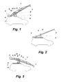
Figure 1 shows a view of a vehicle that incorporates a filming crane with the counterweight system leveled relative to the plane of the ground in accordance with the present invention. -
Figure 2 shows a simplified view of a vehicle with a filming crane similar to that of the preceding figure wherein it is contrasted the present invention with the result of the earlier art by means of broken lines. -
Figure 3 shows another representation of the vehicle with the filming crane offigure 1 but with the counterweight system elevated and the filming crane at a low point. The counterweight system is kept leveled relative to the ground in accordance with the present invention. -
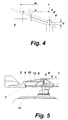
Figure 4 represents a schematic detail of the variation of position relative to the center of gyration of the crane from the center of gravity of the counterweight system showing the known art in broken lines and the present invention in solid lines. -
Figure 5 provides an enlarged detail of the leveling mechanism of the present invention. - The present invention consists of a counterweight balancing device for filming cranes of the type of cranes that are mounted onto vehicles adapted for receiving said cranes and intended to record images while in motion, wherein the crane incorporates a pantograph that enables leveling of the counterweight system (2).
- The crane (1) supports at both its opposite end arms the counterweight system (2) that balances the camera (3) or the camera head which enables rotation of said arms, as if on a balance, from its pointer or middle point, which is the center of gyration (4) of the crane. In the earlier art, which the present invention improves, the center of gyration of the crane (4') is to be kept away from the vehicle, see
figure 2 , in order to avoid collision of the counterweight system (2) or the camera (3) with the vehicle bodywork and to enable and ample movement of the camera. - Obviously, if it were possible to lower the center of gyration of the crane at the central shaft thereof (5), it would be possible to obtain a more stable and safer assembly as the mass center of the crane would also be lowered as a result, so that the crane would undergo less inertia while in motion and it would be facilitated both driving of the vehicle and the filming tasks.
- To achieve the above object the invention incorporates a pantograph mechanism thanks to the articulations (6 and 7) of the counterweight system (2) and the articulations (8) of a shaft (9) associated to the center of gyration (4) of the crane and the presence in said center of gyration (4). Articulations (6 and 8) are joined together by means of a crossbar (10).
- The articulations (7) of the counterweight system (2) and the one corresponding to the center of gyration (4) of the crane are connected by shaft (11), which is a part of the shaft or arm of the crane.
- Furthermore, articulations (6 and 7) and articulations (4 and 8) are respectively connected by bars or shafts (9 and 9')
- The enlarged detail of
figure 5 permits to appreciate the details of this pantograph that is incorporated to the balance of the counterweight system (2) of the crane (1). - Operation is simple. When, for instance, the camera (3). is lifted by the crane (1), it takes place an opposite oscillation in the counterweight system (2).
Figure 4 shows the elevated height of the center of gyration (4') of the state of the art represented in broken lines relative to the center of gyration (4) of the present invention, represented in solid lines. The difference in height "h" is inevitable because the arms of the crane must in the known art avoid, with a lesser radius of gyration, the vehicle bodywork. - In the present invention articulations (6 and 8) are pushed forward of the central shaft (5) of the crane, keeping the verticality of axles (9 and 9') relative to the ground, such that thanks to articulations (6 and 7) the counterweight system always stays in a horizontal position.
- The same occurs when the crane lowers the camera (3) close to the ground. The counterweight system (2) is lifted and articulations (6 and 8) move backwards relative to the central shaft (5) of the crane (1) while keeping at all times shafts (9 and 9') vertical to the ground and the counterweight system (2) leveled and parallel to the ground.
- The geometry of the movement of the counterweight system (2), in accordance with what has been described above, enables to design a crane with a lower pointer or center of gyration (4) and a mass center closer to the ground, thereby it being obtained one of the main objects of the present invention.
- However, proceeding as described above brings about a further problem that has to be solved. As shown in
figure 4 , keeping the counterweight system (2) leveled relative to the plane of the ground causes the mass center of said counterweight system (2) to be closer to the central shaft (5) of the crane, (n<m), which would result in a smaller momentum that would in turn disturb the balance of the crane arms (1). - In order to solve this problem it is included a means of elastic resistance, such as a gas cylinder (12) that acts against the movement of approximation of the counterweight system (2) towards the central shaft (5) of the crane. Said counterweight system (2) must exercise some force against said pneumatic cylinder (12) for balancing the loss of leverage resulting from said approximation.
- This gas cylinder (12) basically comprises a jacket that forms a cylinder containing gas at a certain pressure against which a piston pushed by a shaft or rod works. When the rod wants to come out it needs an effort or tractive work. By adjusting the pressure in the interior of the jacket it is facilitated movement or is increased the effort to move the rod.
- The result is an adjustable and utterly stable assembly with a center of gravity that is lower than that of the prior art and is characterized in that it always keeps leveled the counterweight system (2) relative to the ground.
- It is understood that in the present case details with regard to finishing and form may be variable insofar as they do not modify the basic idea of the invention.
Claims (5)
- COUNTERWEIGHT BALANCING DEVICE FOR FILMING CRANES of the type of cranes mounted onto vehicles adapted for receiving said cranes and intended to record images while in motion, said crane (1) having a center of gyration (4) from both sides of which oscillate as if on a balance a counterweight system (2) and on the opposite side oscillates a camera and/or filming head (3), CHARACTERIZED in that it is provided with a pantograph mechanism that enables to keep said counterweight system (2) leveled relative to the ground against any ascending or descending movement of the arm that supports the filming camera (3).
- COUNTERWEIGHT BALANCING DEVICE FOR FILMING CRANES, according to claim 1, CHARACTERIZED in that it is provided with articulations (6, 7, 8 and 9), fixed shafts (10 and 11) and movable shafts (9 and 9') relative to the central shaft (5) of the crane, thereby forming said pantograph mechanism.
- COUNTERWEIGHT BALANCING DEVICE FOR FILMING CRANES, according to any of the previous claims, CHARACTERIZED in that it is provided with an elastic resistance means against the relative forward and backward movements of said counterweight system (2) relative to the central shaft (5) of the crane for offsetting the variation of momentum caused by said movement.
- COUNTERWEIGHT BALANCING DEVICE FOR FILMING CRANES, according to the previous claim, CHARACTERIZED in that said elastic means is a gas spring (12).
- COUNTERWEIGHT BALANCING DEVICE FOR FILMING CRANES, according to the previous claim, CHARACTERIZED in that the gas pressure of said gas spring (12) is adjustable.
Priority Applications (1)
| Application Number | Priority Date | Filing Date | Title |
|---|---|---|---|
| PL12881737T PL2878568T3 (en) | 2012-07-24 | 2012-12-20 | Counterweight balancing device for filming cranes |
Applications Claiming Priority (2)
| Application Number | Priority Date | Filing Date | Title |
|---|---|---|---|
| ES201200756A ES2444315B1 (en) | 2012-07-24 | 2012-07-24 | Shooting crane balance weights device |
| PCT/ES2012/000320 WO2014016441A1 (en) | 2012-07-24 | 2012-12-20 | Counterweight balancing device for filming cranes |
Publications (3)
| Publication Number | Publication Date |
|---|---|
| EP2878568A1 true EP2878568A1 (en) | 2015-06-03 |
| EP2878568A4 EP2878568A4 (en) | 2016-09-28 |
| EP2878568B1 EP2878568B1 (en) | 2020-09-30 |
Family
ID=49996637
Family Applications (1)
| Application Number | Title | Priority Date | Filing Date |
|---|---|---|---|
| EP12881737.6A Active EP2878568B1 (en) | 2012-07-24 | 2012-12-20 | Counterweight balancing device for filming cranes |
Country Status (5)
| Country | Link |
|---|---|
| US (1) | US9440832B2 (en) |
| EP (1) | EP2878568B1 (en) |
| ES (2) | ES2444315B1 (en) |
| PL (1) | PL2878568T3 (en) |
| WO (1) | WO2014016441A1 (en) |
Cited By (1)
| Publication number | Priority date | Publication date | Assignee | Title |
|---|---|---|---|---|
| WO2018100168A1 (en) * | 2016-12-02 | 2018-06-07 | Plogstedt Timo | Camera arm |
Families Citing this family (7)
| Publication number | Priority date | Publication date | Assignee | Title |
|---|---|---|---|---|
| GB2523401B (en) * | 2014-02-25 | 2017-02-15 | Caterpillar Inc | Receiver assembly |
| US20220002128A1 (en) * | 2020-04-09 | 2022-01-06 | Chapman/Leonard Studio Equipment, Inc. | Telescoping electric camera crane |
| US11422437B2 (en) * | 2020-04-09 | 2022-08-23 | Chapman/Leonard Studio Equipment, Inc. | Telescoping electric camera crane |
| CN214700041U (en) * | 2021-05-10 | 2021-11-12 | 河南猎影智能科技有限公司 | Vehicle-mounted rocker arm shooting system with ultralow height and no balance weight |
| US12523924B2 (en) * | 2022-09-12 | 2026-01-13 | Tilta Inc. | Vehicle-mounted camera crane |
| CN115520066A (en) * | 2022-10-25 | 2022-12-27 | 厚泰(湖北)起重设备有限公司 | Pantograph-catenary power receiving system and application thereof in bridge crane |
| CN117819412B (en) * | 2024-01-08 | 2025-12-09 | 徐州重型机械有限公司 | Sliding counterweight mechanism based on luffing linkage and crane |
Family Cites Families (12)
| Publication number | Priority date | Publication date | Assignee | Title |
|---|---|---|---|---|
| FR2380492A1 (en) * | 1977-02-10 | 1978-09-08 | Coutant Andre | Portable support for mounting camera on shoulder - has camera mounted on parallelogram linkage with adjustable tension spring to balance weight |
| GB8622879D0 (en) * | 1986-09-23 | 1986-10-29 | Dsam Ltd | Camera support systems |
| FR2626957A1 (en) * | 1988-02-04 | 1989-08-11 | Gordon Patrick | Lightweight boom for taking photographs |
| NL9000830A (en) * | 1990-04-09 | 1991-11-01 | Egripment B V | BALANCED SUPPORT ARM. |
| DE4326477C2 (en) * | 1993-08-06 | 1995-12-07 | Movietech Filmgeraete Gmbh | Device for releasably connecting a guide rod |
| NL194514C (en) * | 1994-09-06 | 2002-06-04 | Egripment B V | Camera crane as well as gravity correcting means for this. |
| US6752541B1 (en) * | 2003-02-28 | 2004-06-22 | John Dykyj | Camera jib |
| US7522213B2 (en) | 2004-04-16 | 2009-04-21 | Chapman/Leonard Studio Equipment | Shock and vibration isolator for a camera |
| US7137747B2 (en) * | 2004-04-16 | 2006-11-21 | Chapman/Leonard Studio Equipment | Shock and vibration isolator for a camera |
| FR2880337B1 (en) * | 2005-01-05 | 2007-04-06 | Realisation D App De Manutenti | ARROW CRANE WITH AUXILIARY ARM MAY BE VERTICAL MAINTAINED |
| US8403486B2 (en) * | 2009-08-06 | 2013-03-26 | Leonard T. Chapman | Hydraulic shutoff control valve system for a camera crane |
| US8033742B1 (en) * | 2010-04-15 | 2011-10-11 | Chapman/Leonard Studio Equipment, Inc. | Telescoping camera crane |
-
2012
- 2012-07-24 ES ES201200756A patent/ES2444315B1/en not_active Expired - Fee Related
- 2012-12-20 ES ES12881737T patent/ES2841001T3/en active Active
- 2012-12-20 WO PCT/ES2012/000320 patent/WO2014016441A1/en not_active Ceased
- 2012-12-20 PL PL12881737T patent/PL2878568T3/en unknown
- 2012-12-20 US US14/417,128 patent/US9440832B2/en active Active
- 2012-12-20 EP EP12881737.6A patent/EP2878568B1/en active Active
Cited By (1)
| Publication number | Priority date | Publication date | Assignee | Title |
|---|---|---|---|---|
| WO2018100168A1 (en) * | 2016-12-02 | 2018-06-07 | Plogstedt Timo | Camera arm |
Also Published As
| Publication number | Publication date |
|---|---|
| ES2444315A1 (en) | 2014-02-24 |
| EP2878568B1 (en) | 2020-09-30 |
| US20150210521A1 (en) | 2015-07-30 |
| WO2014016441A1 (en) | 2014-01-30 |
| US9440832B2 (en) | 2016-09-13 |
| EP2878568A4 (en) | 2016-09-28 |
| PL2878568T3 (en) | 2021-04-06 |
| ES2444315B1 (en) | 2014-12-03 |
| ES2841001T3 (en) | 2021-07-07 |
Similar Documents
| Publication | Publication Date | Title |
|---|---|---|
| EP2878568B1 (en) | Counterweight balancing device for filming cranes | |
| US9193243B2 (en) | Vehicle suspension system | |
| US10012286B2 (en) | Vehicle vibration device | |
| KR20200116997A (en) | Vehicle-mounted stabilization platform system based on active suspension and its control method | |
| US11235666B2 (en) | Vehicle for travelling along a linear route guideway | |
| EP3003840B1 (en) | Arrangement and method for enabling rotation movement between tandem or caterpillar axle and body of vehicle | |
| EP3169540B1 (en) | Vehicle with three or more wheels provided with an anti-roll stabiliser device and anti-roll control method of a vehicle having at least three wheels | |
| CN102358600A (en) | Gravity center self-balance device for high-order picking truck | |
| US11001121B2 (en) | Vehicular suspension device | |
| EP2848490A1 (en) | Suspension control system | |
| CN106644529B (en) | Vehicle side-tipping test bed | |
| CN115056619B (en) | An adjustable electromagnetic suspension trolley | |
| CN107054182A (en) | Suspension arrangement and method | |
| CN104843599A (en) | Counterweight device of crane and crane with counterweight device | |
| JP5297443B2 (en) | Vehicle and traveling device thereof | |
| CN106965722A (en) | Vehicular vibration device | |
| CN113602960A (en) | Ground transport tool | |
| CN104444823A (en) | Novel bridge-frame crane | |
| CN105620472A (en) | Pressure center position compensation method and device for mobile scanning car | |
| CN202379611U (en) | Crane and mobile cab | |
| CN103863045B (en) | For compensating the device of body movement | |
| CN212685726U (en) | Low-cost large-load AGV moving chassis | |
| CN111114678B (en) | Tricycle electric vehicle capable of increasing stability through gyroscopes and vehicle body balancing method thereof | |
| CN104108421A (en) | Suspension steering device for hub direct-driving electric vehicle | |
| CN211056508U (en) | Movable X-shaped hanger upper frame |
Legal Events
| Date | Code | Title | Description |
|---|---|---|---|
| PUAI | Public reference made under article 153(3) epc to a published international application that has entered the european phase |
Free format text: ORIGINAL CODE: 0009012 |
|
| 17P | Request for examination filed |
Effective date: 20150219 |
|
| AK | Designated contracting states |
Kind code of ref document: A1 Designated state(s): AL AT BE BG CH CY CZ DE DK EE ES FI FR GB GR HR HU IE IS IT LI LT LU LV MC MK MT NL NO PL PT RO RS SE SI SK SM TR |
|
| AX | Request for extension of the european patent |
Extension state: BA ME |
|
| DAX | Request for extension of the european patent (deleted) | ||
| RA4 | Supplementary search report drawn up and despatched (corrected) |
Effective date: 20160825 |
|
| RIC1 | Information provided on ipc code assigned before grant |
Ipc: B66F 13/00 20060101ALI20160819BHEP Ipc: B66F 11/00 20060101ALI20160819BHEP Ipc: B66F 11/04 20060101ALI20160819BHEP Ipc: F16M 13/00 20060101ALI20160819BHEP Ipc: B66C 23/72 20060101AFI20160819BHEP |
|
| STAA | Information on the status of an ep patent application or granted ep patent |
Free format text: STATUS: EXAMINATION IS IN PROGRESS |
|
| 17Q | First examination report despatched |
Effective date: 20180712 |
|
| GRAP | Despatch of communication of intention to grant a patent |
Free format text: ORIGINAL CODE: EPIDOSNIGR1 |
|
| STAA | Information on the status of an ep patent application or granted ep patent |
Free format text: STATUS: GRANT OF PATENT IS INTENDED |
|
| INTG | Intention to grant announced |
Effective date: 20200206 |
|
| GRAS | Grant fee paid |
Free format text: ORIGINAL CODE: EPIDOSNIGR3 |
|
| GRAA | (expected) grant |
Free format text: ORIGINAL CODE: 0009210 |
|
| STAA | Information on the status of an ep patent application or granted ep patent |
Free format text: STATUS: THE PATENT HAS BEEN GRANTED |
|
| AK | Designated contracting states |
Kind code of ref document: B1 Designated state(s): AL AT BE BG CH CY CZ DE DK EE ES FI FR GB GR HR HU IE IS IT LI LT LU LV MC MK MT NL NO PL PT RO RS SE SI SK SM TR |
|
| REG | Reference to a national code |
Ref country code: GB Ref legal event code: FG4D Ref country code: CH Ref legal event code: EP |
|
| REG | Reference to a national code |
Ref country code: AT Ref legal event code: REF Ref document number: 1318601 Country of ref document: AT Kind code of ref document: T Effective date: 20201015 |
|
| REG | Reference to a national code |
Ref country code: DE Ref legal event code: R096 Ref document number: 602012072614 Country of ref document: DE |
|
| REG | Reference to a national code |
Ref country code: IE Ref legal event code: FG4D |
|
| PG25 | Lapsed in a contracting state [announced via postgrant information from national office to epo] |
Ref country code: GR Free format text: LAPSE BECAUSE OF FAILURE TO SUBMIT A TRANSLATION OF THE DESCRIPTION OR TO PAY THE FEE WITHIN THE PRESCRIBED TIME-LIMIT Effective date: 20201231 Ref country code: NO Free format text: LAPSE BECAUSE OF FAILURE TO SUBMIT A TRANSLATION OF THE DESCRIPTION OR TO PAY THE FEE WITHIN THE PRESCRIBED TIME-LIMIT Effective date: 20201230 Ref country code: FI Free format text: LAPSE BECAUSE OF FAILURE TO SUBMIT A TRANSLATION OF THE DESCRIPTION OR TO PAY THE FEE WITHIN THE PRESCRIBED TIME-LIMIT Effective date: 20200930 Ref country code: SE Free format text: LAPSE BECAUSE OF FAILURE TO SUBMIT A TRANSLATION OF THE DESCRIPTION OR TO PAY THE FEE WITHIN THE PRESCRIBED TIME-LIMIT Effective date: 20200930 Ref country code: HR Free format text: LAPSE BECAUSE OF FAILURE TO SUBMIT A TRANSLATION OF THE DESCRIPTION OR TO PAY THE FEE WITHIN THE PRESCRIBED TIME-LIMIT Effective date: 20200930 Ref country code: BG Free format text: LAPSE BECAUSE OF FAILURE TO SUBMIT A TRANSLATION OF THE DESCRIPTION OR TO PAY THE FEE WITHIN THE PRESCRIBED TIME-LIMIT Effective date: 20201230 |
|
| REG | Reference to a national code |
Ref country code: AT Ref legal event code: MK05 Ref document number: 1318601 Country of ref document: AT Kind code of ref document: T Effective date: 20200930 |
|
| PG25 | Lapsed in a contracting state [announced via postgrant information from national office to epo] |
Ref country code: RS Free format text: LAPSE BECAUSE OF FAILURE TO SUBMIT A TRANSLATION OF THE DESCRIPTION OR TO PAY THE FEE WITHIN THE PRESCRIBED TIME-LIMIT Effective date: 20200930 Ref country code: LV Free format text: LAPSE BECAUSE OF FAILURE TO SUBMIT A TRANSLATION OF THE DESCRIPTION OR TO PAY THE FEE WITHIN THE PRESCRIBED TIME-LIMIT Effective date: 20200930 |
|
| REG | Reference to a national code |
Ref country code: NL Ref legal event code: MP Effective date: 20200930 |
|
| REG | Reference to a national code |
Ref country code: LT Ref legal event code: MG4D |
|
| PG25 | Lapsed in a contracting state [announced via postgrant information from national office to epo] |
Ref country code: SM Free format text: LAPSE BECAUSE OF FAILURE TO SUBMIT A TRANSLATION OF THE DESCRIPTION OR TO PAY THE FEE WITHIN THE PRESCRIBED TIME-LIMIT Effective date: 20200930 Ref country code: RO Free format text: LAPSE BECAUSE OF FAILURE TO SUBMIT A TRANSLATION OF THE DESCRIPTION OR TO PAY THE FEE WITHIN THE PRESCRIBED TIME-LIMIT Effective date: 20200930 Ref country code: NL Free format text: LAPSE BECAUSE OF FAILURE TO SUBMIT A TRANSLATION OF THE DESCRIPTION OR TO PAY THE FEE WITHIN THE PRESCRIBED TIME-LIMIT Effective date: 20200930 Ref country code: PT Free format text: LAPSE BECAUSE OF FAILURE TO SUBMIT A TRANSLATION OF THE DESCRIPTION OR TO PAY THE FEE WITHIN THE PRESCRIBED TIME-LIMIT Effective date: 20210201 Ref country code: LT Free format text: LAPSE BECAUSE OF FAILURE TO SUBMIT A TRANSLATION OF THE DESCRIPTION OR TO PAY THE FEE WITHIN THE PRESCRIBED TIME-LIMIT Effective date: 20200930 Ref country code: EE Free format text: LAPSE BECAUSE OF FAILURE TO SUBMIT A TRANSLATION OF THE DESCRIPTION OR TO PAY THE FEE WITHIN THE PRESCRIBED TIME-LIMIT Effective date: 20200930 |
|
| PG25 | Lapsed in a contracting state [announced via postgrant information from national office to epo] |
Ref country code: IS Free format text: LAPSE BECAUSE OF FAILURE TO SUBMIT A TRANSLATION OF THE DESCRIPTION OR TO PAY THE FEE WITHIN THE PRESCRIBED TIME-LIMIT Effective date: 20210130 Ref country code: AL Free format text: LAPSE BECAUSE OF FAILURE TO SUBMIT A TRANSLATION OF THE DESCRIPTION OR TO PAY THE FEE WITHIN THE PRESCRIBED TIME-LIMIT Effective date: 20200930 Ref country code: AT Free format text: LAPSE BECAUSE OF FAILURE TO SUBMIT A TRANSLATION OF THE DESCRIPTION OR TO PAY THE FEE WITHIN THE PRESCRIBED TIME-LIMIT Effective date: 20200930 |
|
| PG25 | Lapsed in a contracting state [announced via postgrant information from national office to epo] |
Ref country code: SK Free format text: LAPSE BECAUSE OF FAILURE TO SUBMIT A TRANSLATION OF THE DESCRIPTION OR TO PAY THE FEE WITHIN THE PRESCRIBED TIME-LIMIT Effective date: 20200930 |
|
| REG | Reference to a national code |
Ref country code: DE Ref legal event code: R119 Ref document number: 602012072614 Country of ref document: DE |
|
| REG | Reference to a national code |
Ref country code: ES Ref legal event code: FG2A Ref document number: 2841001 Country of ref document: ES Kind code of ref document: T3 Effective date: 20210707 |
|
| REG | Reference to a national code |
Ref country code: CH Ref legal event code: PL |
|
| PLBE | No opposition filed within time limit |
Free format text: ORIGINAL CODE: 0009261 |
|
| STAA | Information on the status of an ep patent application or granted ep patent |
Free format text: STATUS: NO OPPOSITION FILED WITHIN TIME LIMIT |
|
| GBPC | Gb: european patent ceased through non-payment of renewal fee |
Effective date: 20201230 |
|
| PG25 | Lapsed in a contracting state [announced via postgrant information from national office to epo] |
Ref country code: DK Free format text: LAPSE BECAUSE OF FAILURE TO SUBMIT A TRANSLATION OF THE DESCRIPTION OR TO PAY THE FEE WITHIN THE PRESCRIBED TIME-LIMIT Effective date: 20200930 Ref country code: MC Free format text: LAPSE BECAUSE OF FAILURE TO SUBMIT A TRANSLATION OF THE DESCRIPTION OR TO PAY THE FEE WITHIN THE PRESCRIBED TIME-LIMIT Effective date: 20200930 |
|
| REG | Reference to a national code |
Ref country code: BE Ref legal event code: MM Effective date: 20201231 |
|
| 26N | No opposition filed |
Effective date: 20210701 |
|
| PG25 | Lapsed in a contracting state [announced via postgrant information from national office to epo] |
Ref country code: IT Free format text: LAPSE BECAUSE OF FAILURE TO SUBMIT A TRANSLATION OF THE DESCRIPTION OR TO PAY THE FEE WITHIN THE PRESCRIBED TIME-LIMIT Effective date: 20200930 Ref country code: IE Free format text: LAPSE BECAUSE OF NON-PAYMENT OF DUE FEES Effective date: 20201220 Ref country code: LU Free format text: LAPSE BECAUSE OF NON-PAYMENT OF DUE FEES Effective date: 20201220 Ref country code: FR Free format text: LAPSE BECAUSE OF NON-PAYMENT OF DUE FEES Effective date: 20201231 |
|
| PG25 | Lapsed in a contracting state [announced via postgrant information from national office to epo] |
Ref country code: LI Free format text: LAPSE BECAUSE OF NON-PAYMENT OF DUE FEES Effective date: 20201231 Ref country code: SI Free format text: LAPSE BECAUSE OF FAILURE TO SUBMIT A TRANSLATION OF THE DESCRIPTION OR TO PAY THE FEE WITHIN THE PRESCRIBED TIME-LIMIT Effective date: 20200930 Ref country code: GB Free format text: LAPSE BECAUSE OF NON-PAYMENT OF DUE FEES Effective date: 20201230 Ref country code: CH Free format text: LAPSE BECAUSE OF NON-PAYMENT OF DUE FEES Effective date: 20201231 Ref country code: DE Free format text: LAPSE BECAUSE OF NON-PAYMENT OF DUE FEES Effective date: 20210701 |
|
| PG25 | Lapsed in a contracting state [announced via postgrant information from national office to epo] |
Ref country code: IS Free format text: LAPSE BECAUSE OF FAILURE TO SUBMIT A TRANSLATION OF THE DESCRIPTION OR TO PAY THE FEE WITHIN THE PRESCRIBED TIME-LIMIT Effective date: 20210130 Ref country code: TR Free format text: LAPSE BECAUSE OF FAILURE TO SUBMIT A TRANSLATION OF THE DESCRIPTION OR TO PAY THE FEE WITHIN THE PRESCRIBED TIME-LIMIT Effective date: 20200930 Ref country code: MT Free format text: LAPSE BECAUSE OF FAILURE TO SUBMIT A TRANSLATION OF THE DESCRIPTION OR TO PAY THE FEE WITHIN THE PRESCRIBED TIME-LIMIT Effective date: 20200930 Ref country code: CY Free format text: LAPSE BECAUSE OF FAILURE TO SUBMIT A TRANSLATION OF THE DESCRIPTION OR TO PAY THE FEE WITHIN THE PRESCRIBED TIME-LIMIT Effective date: 20200930 |
|
| PG25 | Lapsed in a contracting state [announced via postgrant information from national office to epo] |
Ref country code: MK Free format text: LAPSE BECAUSE OF FAILURE TO SUBMIT A TRANSLATION OF THE DESCRIPTION OR TO PAY THE FEE WITHIN THE PRESCRIBED TIME-LIMIT Effective date: 20200930 |
|
| PG25 | Lapsed in a contracting state [announced via postgrant information from national office to epo] |
Ref country code: BE Free format text: LAPSE BECAUSE OF NON-PAYMENT OF DUE FEES Effective date: 20201231 |
|
| PGFP | Annual fee paid to national office [announced via postgrant information from national office to epo] |
Ref country code: CZ Payment date: 20251105 Year of fee payment: 14 |
|
| PGFP | Annual fee paid to national office [announced via postgrant information from national office to epo] |
Ref country code: PL Payment date: 20251023 Year of fee payment: 14 |
|
| PGFP | Annual fee paid to national office [announced via postgrant information from national office to epo] |
Ref country code: ES Payment date: 20260126 Year of fee payment: 14 |