EP2878516A1 - Apparatus and method for controlling head-in perpendicular parking of vehicle, and system for head-in perpendicular parking of vehicle with the apparatus - Google Patents
Apparatus and method for controlling head-in perpendicular parking of vehicle, and system for head-in perpendicular parking of vehicle with the apparatus Download PDFInfo
- Publication number
- EP2878516A1 EP2878516A1 EP14152676.4A EP14152676A EP2878516A1 EP 2878516 A1 EP2878516 A1 EP 2878516A1 EP 14152676 A EP14152676 A EP 14152676A EP 2878516 A1 EP2878516 A1 EP 2878516A1
- Authority
- EP
- European Patent Office
- Prior art keywords
- parking
- vehicle
- head
- parking area
- control unit
- Prior art date
- Legal status (The legal status is an assumption and is not a legal conclusion. Google has not performed a legal analysis and makes no representation as to the accuracy of the status listed.)
- Granted
Links
Images









Classifications
-
- B—PERFORMING OPERATIONS; TRANSPORTING
- B62—LAND VEHICLES FOR TRAVELLING OTHERWISE THAN ON RAILS
- B62D—MOTOR VEHICLES; TRAILERS
- B62D15/00—Steering not otherwise provided for
- B62D15/02—Steering position indicators ; Steering position determination; Steering aids
- B62D15/027—Parking aids, e.g. instruction means
- B62D15/0285—Parking performed automatically
-
- B—PERFORMING OPERATIONS; TRANSPORTING
- B60—VEHICLES IN GENERAL
- B60W—CONJOINT CONTROL OF VEHICLE SUB-UNITS OF DIFFERENT TYPE OR DIFFERENT FUNCTION; CONTROL SYSTEMS SPECIALLY ADAPTED FOR HYBRID VEHICLES; ROAD VEHICLE DRIVE CONTROL SYSTEMS FOR PURPOSES NOT RELATED TO THE CONTROL OF A PARTICULAR SUB-UNIT
- B60W30/00—Purposes of road vehicle drive control systems not related to the control of a particular sub-unit, e.g. of systems using conjoint control of vehicle sub-units
- B60W30/06—Automatic manoeuvring for parking
-
- B—PERFORMING OPERATIONS; TRANSPORTING
- B60—VEHICLES IN GENERAL
- B60W—CONJOINT CONTROL OF VEHICLE SUB-UNITS OF DIFFERENT TYPE OR DIFFERENT FUNCTION; CONTROL SYSTEMS SPECIALLY ADAPTED FOR HYBRID VEHICLES; ROAD VEHICLE DRIVE CONTROL SYSTEMS FOR PURPOSES NOT RELATED TO THE CONTROL OF A PARTICULAR SUB-UNIT
- B60W10/00—Conjoint control of vehicle sub-units of different type or different function
- B60W10/20—Conjoint control of vehicle sub-units of different type or different function including control of steering systems
-
- B—PERFORMING OPERATIONS; TRANSPORTING
- B60—VEHICLES IN GENERAL
- B60W—CONJOINT CONTROL OF VEHICLE SUB-UNITS OF DIFFERENT TYPE OR DIFFERENT FUNCTION; CONTROL SYSTEMS SPECIALLY ADAPTED FOR HYBRID VEHICLES; ROAD VEHICLE DRIVE CONTROL SYSTEMS FOR PURPOSES NOT RELATED TO THE CONTROL OF A PARTICULAR SUB-UNIT
- B60W30/00—Purposes of road vehicle drive control systems not related to the control of a particular sub-unit, e.g. of systems using conjoint control of vehicle sub-units
- B60W30/08—Active safety systems predicting or avoiding probable or impending collision or attempting to minimise its consequences
-
- B—PERFORMING OPERATIONS; TRANSPORTING
- B60—VEHICLES IN GENERAL
- B60W—CONJOINT CONTROL OF VEHICLE SUB-UNITS OF DIFFERENT TYPE OR DIFFERENT FUNCTION; CONTROL SYSTEMS SPECIALLY ADAPTED FOR HYBRID VEHICLES; ROAD VEHICLE DRIVE CONTROL SYSTEMS FOR PURPOSES NOT RELATED TO THE CONTROL OF A PARTICULAR SUB-UNIT
- B60W30/00—Purposes of road vehicle drive control systems not related to the control of a particular sub-unit, e.g. of systems using conjoint control of vehicle sub-units
- B60W30/18—Propelling the vehicle
-
- B—PERFORMING OPERATIONS; TRANSPORTING
- B62—LAND VEHICLES FOR TRAVELLING OTHERWISE THAN ON RAILS
- B62D—MOTOR VEHICLES; TRAILERS
- B62D5/00—Power-assisted or power-driven steering
- B62D5/04—Power-assisted or power-driven steering electrical, e.g. using an electric servo-motor connected to, or forming part of, the steering gear
- B62D5/0457—Power-assisted or power-driven steering electrical, e.g. using an electric servo-motor connected to, or forming part of, the steering gear characterised by control features of the drive means as such
- B62D5/046—Controlling the motor
-
- G—PHYSICS
- G08—SIGNALLING
- G08G—TRAFFIC CONTROL SYSTEMS
- G08G1/00—Traffic control systems for road vehicles
- G08G1/16—Anti-collision systems
- G08G1/165—Anti-collision systems for passive traffic, e.g. including static obstacles, trees
Definitions
- the present invention relates to an apparatus and a method for controlling head-in perpendicular parking of a vehicle, which front the vehicle to be subjected to head-in perpendicular parking in a parking area positioned perpendicular to a fronting direction of the vehicle to be parked, and a system for perpendicular head-in parking of the vehicle with the apparatus.
- the parking problem has become a serious issue, and as a result, as the number of vehicles increase in limited areas, cities, and nations, parking areas where the vehicles can be parked cannot but be reduced and a parking section sectioned to park one vehicle has been gradually narrowed in order to solve an insufficient parking area.
- an automatic parking system in a vehicle and automatically parks the vehicle by checking images obtained by photographing surroundings of the vehicle in the automatic parking system.
- the automatic parking system assists parking by automatically steering the vehicle or assists parallel parking by sensing surrounding obstacles with a distance sensor by installing the distance sensor, and the like on the side of the vehicle when the driver performs perpendicular or parallel parking in the parking area by using a camera installed at the rear of the vehicle.
- the general automatic parking system just gives an alarm by sensing the obstacles or notifies the driver that there is a risk that the vehicle will collide with the obstacles while automatically parking the vehicle and does not generate an accurate path for evading the obstacles in the parking area, and as a result, the driver needs to determine a path to avoid the obstacles visually or using another equipment or avoid the obstacles by personally driving the vehicle. Therefore, a driver's convenience cannot be considered.
- Korean Patent Application Laid-Open No. 2009-0036794 discloses a parking assisting device.
- this device supports a perpendicular back-in parking method and is impossible to support a perpendicular head-in parking method.
- the present invention has been made in an effort to provide an apparatus and a method for head-in perpendicular parking of a vehicle, which support a head-in perpendicular parking method and a system for head-in perpendicular parking of a vehicle with the apparatus.
- An exemplary embodiment of the present invention provides an apparatus for controlling head-in orthogonal parking of a vehicle, the apparatus including: a parking area detecting unit configured to detect a parking area; a backward control unit configured to generate a backward path based on positional information of obstacles positioned within a predetermined distance from the parking area and back the vehicle based on the backward path; a head-in parking determination unit configured to judge whether head-in parking in the parking area is available; a forward control unit configured to generate a forward path based on the positional information of the obstacles or positional information of a sectioning line to determine the parking area when it is judged that head-in parking in the parking area is unavailable and front the vehicle based on the forward path; a main control unit configured to repeat a backward control and a forward control of the vehicle until it is judged that head-in parking in the parking area is available; and a parking control unit configured to generate a parking path based on the positional information of the obstacles or the positional information of the sectioning line when it is judged that
- the parking control unit may finally park the vehicle by aligning a temporarily parked vehicle according to the parking path based on positional information of an obstacle or a sectioning line positioned at at least one side of the parking area.
- the parking control unit may compare distances from the temporarily parked vehicle to each obstacle or each sectioning line positioned at both sides of the parking area to align the temporarily parked vehicle, and when the obstacle or the sectioning line is positioned only at one side of the parking area, the parking control unit may align the temporarily parked vehicle so as to maintain a designated distance from the obstacle or the sectioning line positioned at one side of the parking area.
- the backward control unit may calculate a reachable location and a rotational angle up to the location and generate the backward path based on the reachable location and the rotational angle.
- the backward control unit may calculate a turning center point of the vehicle, calculate a turning radius from a present location to a front outermost point, and calculate the rotational angle so that a nearest point from the obstacles to the front outermost point is larger than a collision avoidance margin.
- the backward control unit may calculate the turning radius based on an overall length of the vehicle, an overall width of the vehicle, and a rear overhang and calculate a nearest point from the obstacles to the front outermost point by using a difference value between the turning center point and the turning radius.
- the backward control unit may calculate the reachable location based on a turning radius in the first backing, an overall width of the vehicle, a rear overhang, an initial location of the vehicle, an initial heading angle of the vehicle, a width of a road where the vehicle is driven, and a front/rear collision avoidance margin of the vehicle, in initial fronting.
- the backward control unit may calculate the reachable location based on a minimum turning radius of the vehicle, an overall width of the vehicle, a rear overhang, a previous location of the vehicle, a previous heading angle of the vehicle, a width of a road where the vehicle is driven, and a front/rear collision avoidance margin of the vehicle, from subsequent backing in the initial backing.
- the head-in parking determination unit may calculate the front collision avoidance margin of the vehicle and compare the front collision avoidance margin and a reference value to determine whether head-in parking in the parking area is available.
- the head-in parking determination unit may calculate the front collision avoidance margin based on the target location of the vehicle, the overall length of the vehicle, the rear overhang, the target heading angle of the vehicle, and the overall width of the vehicle.
- the forward control unit may calculate a reachable location and a rotational angle up to the location, and generate the forward path based on the reachable location and the rotational angle.
- the forward control unit may calculate the reachable location based on the target location of the vehicle, the overall length of the vehicle, the rear overhang, the target heading angle of the vehicle, and the overall width of the vehicle.
- Another exemplary embodiment of the present invention provides a method for controlling head-in orthogonal parking of a vehicle, the method including: detecting a parking area; generating a backward path based on positional information of obstacles positioned within a predetermined distance from the parking area and backing the vehicle based on the backward path; judging whether head-in parking in the parking area is available; generating a forward path based on the positional information of the obstacles or positional information of a sectioning line to determine the parking area when it is judged that head-in parking in the parking area is unavailable and fronting the vehicle based on the forward path repeating a backward control and a forward control of the vehicle until it is judged that head-in parking in the parking area is available; and generating a parking path based on the positional information of the obstacles or the positional information of the sectioning line when it is judged that head-in parking in the parking area is available and parking the vehicle based on the parking path.
- the vehicle may be finally parked by aligning a temporarily parked vehicle according to the parking path based on positional information of an obstacle or a sectioning line positioned at at least one side of the parking area.
- a reachable location and a rotational angle up to the location may be calculated and the backward path may be generated based on the reachable location and the rotational angle.
- the front collision avoidance margin of the vehicle may be calculated and the front collision avoidance margin and a reference value may be compared to determine whether head-in parking in the parking area is available.
- Yet another exemplary embodiment of the present invention provides a system for head-in perpendicular parking of a vehicle, the system including: a head-in perpendicular parking controlling apparatus including a parking area detecting unit configured to detect a parking area; a backward control unit configured to generate a backward path based on positional information of obstacles positioned within a predetermined distance from the parking area and back the vehicle based on the backward path; a head-in parking determination unit configured to judge whether head-in parking in the parking area is available; a forward control unit configured to generate a forward path based on the positional information of the obstacles or positional information of a sectioning line to determine the parking area when it is judged that head-in parking in the parking area is unavailable and front the vehicle based on the forward path; a main control unit configured to repeat a backward control and a forward control of the vehicle until it is judged that head-in parking in the parking area is available; and a parking control unit configured to generate a parking path based on the positional information of the obstacles or
- automatic parking can be enabled even in head-in parking in addition to the existing back-in parking by supporting a head-in perpendicular parking method. Necessity of head-in perpendicular parking has attracted public attentions due to an environmental problem in recent years.
- the present invention can also solve the problem due to the environmental problem.
- the present invention proposes a system that implements head-in perpendicular parking without adding the existing parking assisting system or a user's input.
- FIG. 1 is a conceptual diagram of a parking assisting system according to an exemplary embodiment of the present invention.
- a parking assisting system 100 relates to a system that supports head-in perpendicular parking and may be implemented by adding only head-in parking path control logic without adding a separate additional device to the existing parking assisting system or a driver's judgment.
- An obstacle sensing unit 110 serves to sense side obstacles.
- a parking area generating unit 130 serves to recognize a parking area based on obstacle information.
- a vehicle sensor unit 120 serves to measure state information of a vehicle.
- the vehicle sensor unit 120 measures a wheel pulse, a steering angle, a speed, a yaw rate, and the like as the state information of the vehicle.
- a vehicle position calculating unit 140 serves to estimate a present location of the vehicle based on the state information of the vehicle.
- a target path generating unit 150 serves to generate a target path from the recognized parking area and the present vehicle location.
- the target path generating unit 150 generates a target path for head-in perpendicular parking.
- a steering command generating unit 160 serves to calculate a steering angle according to the target path.
- a steering control unit 180 serves to perform a steering control based on the steering angle.
- a path following unit 170 serves to modify the target path and control path following when the present location is out of a target location during the steering control.
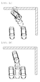
- FIGS. 2A to 2H are conceptual diagrams illustrating a parking assisting process.
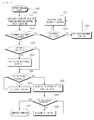
- FIG. 3 is a flowchart sequentially illustrating a parking assisting method of the parking assisting system illustrated in FIG. 1 . The following description will be made with reference to FIGS. 2A to 3 .
- the method for controlling head-in perpendicular parking in the parking assisting system 100 follows a sequence described below.
- FIG. 2A illustrates the parking area searching, that is, step S305.
- a position and an angle which are reachable in an N-th fronting/backing are calculated (S310).
- a whole parking path is calculated based on the reachable position and angle and a control start location is determined to reach the target location.
- FIG. 2B illustrates the evading control, that is, steps S340 and S325
- FIG. 2C illustrates the space securing control, that is, step S330.
- FIG. 2D exemplifies the backward collision.
- FIG. 2E illustrates the attitude control, that is, step S350
- FIG. 2F illustrates the entering control, that is, step S355.
- FIG. 2G illustrates the alignment correction control, that is, step S365 and FIG. 2H is an exemplary diagram when the alignment is satisfied.
- the target path which conforms therewith needs to be generated.
- the target path generating unit 150 generates the target path for the head-in perpendicular parking will be described.
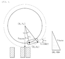
- FIGS. 4A to 6 are reference diagrams for describing a method for calculating a turning radius for evading a collision in first back turning.
- the target path generating unit 150 checks whether a front edge of the vehicle collides in the first back turning and thereafter, calculates the turning radius for evading the collision. A sequence thereof will be described below.
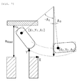
- FIG. 7 is a reference diagram for describing a method for calculating a position which is reachable in first backing.
- FIG. 8 is a reference diagram for describing a method for calculating a position which is reachable in N-th backing.
- FIGS. 9A and 9B are reference diagrams for describing a method for calculating a position which is reachable in N-th fronting.
- FIG. 9A illustrates a case in which space entering is impossible and
- FIG. 9B illustrates a case in which space entering is possible.
- Equation 3 a result of Equation 3 may be acquired.
- a N ⁇ arccos AC ⁇ B ⁇ A 2 + B 2 - C 2 A 2 + B 2
- the vehicle is aligned at N times at which AN reaches -90 degrees and in this case, the control start location is determined to make X N be the same as a parking target location and a whole head-in perpendicular parking path is calculated.
- FIGS. 10 and 11 are reference diagrams illustrating a simulation result of the parking assisting process according to the exemplary embodiment of the present invention.
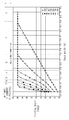
- FIG. 10 illustrates a 90-degree alignment time in the N-th fronting/backing depending on the parking area length and the road width.
- FIG. 11 is a simulation result when the parking area length is approximately 2.66 m (a value acquired by adding the overall width of the vehicle and 0.8 m) and the road width is 6 m. Specially, FIG. 11 illustrates simulation result data by a graph.
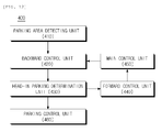
- FIG. 12 is a block diagram schematically illustrating an apparatus for controlling head-in perpendicular parking of a vehicle according to an exemplary embodiment of the present invention.
- a head-in perpendicular parking controlling apparatus 400 includes a parking area detecting unit 410, a backward control unit 420, a head-in parking determination unit 430, a forward control unit 440, a main control unit 450, and a parking control unit 460.
- the head-in perpendicular parking controlling apparatus 400 may further include a power supply unit supplying power to each internal component. However, when it is considered that the head-in perpendicular parking controlling apparatus 400 may be controlled by an in-vehicle main ECU, the head-in perpendicular parking controlling apparatus 400 may not include the power supply unit.
- the parking area detecting unit 410 serves to detect a parking area.
- the backward control unit 420 serves to generate a backward path based on positional information of obstacles positioned within a predetermined distance from the parking area and back the vehicle based on the backward path.
- the backward control unit 420 may calculate the reachable location and a rotational angle up to the location, and generate the backward path based on the reachable location and the rotational angle.
- the backward control unit 420 may calculate the turning center point of the vehicle, calculate a turning radius from the present location to the front outermost point, and calculate the rotational angle so that the nearest point from the obstacles to the front outermost point is larger than the collision avoidance margin.
- the backward control unit 420 may calculate the turning radius based on the overall length of the vehicle, the overall width of the vehicle, and the rear overhang, and calculate the nearest point from the obstacles to the front outermost point by using a difference value between the turning center point and the turning radius.
- the backward control unit 420 may calculate the reachable location based on a turning radius in the first backing, an overall width of the vehicle, a rear overhang, an initial location of the vehicle, an initial heading angle of the vehicle, a width of a road where the vehicle is driven, and a front/rear collision avoidance margin of the vehicle in initial backing.
- the backward control unit 420 may calculate the reachable location based on a minimum turning radius of the vehicle, an overall width of the vehicle, a rear overhang, a previous location of the vehicle, a previous heading angle of the vehicle, a width of a road where the vehicle is driven, and a front/rear collision avoidance margin of the vehicle, from subsequent backing in the initial backing.
- the head-in parking determination unit 430 serves to determine whether head-in parking in the parking area is available.
- the head-in parking determination unit 430 calculates the front collision avoidance margin of the vehicle and compares the front collision avoidance margin and a reference value to determine head-in parking in the parking area is available. In this case, 0 may be used as the reference value.
- the head-in parking determination unit 430 may calculate the front collision avoidance margin based on the target location of the vehicle, the overall length of the vehicle, the rear overhang, the target heading angle of the vehicle, and the overall width of the vehicle.
- the forward control unit 440 serves to generate the forward path based on the positional information of the obstacles or positional information of a sectioning line to determine the parking area when it is judged that head-in parking in the parking area is unavailable and front the vehicle based on the forward path.
- the forward control unit 440 may calculate a reachable location and a rotational angle up to the location, and generate the forward path based on the reachable location and the rotational angle.
- the forward control unit 440 may calculate the reachable location based on the target location of the vehicle, the overall length of the vehicle, the rear overhang, the target heading angle of the vehicle, and the overall width of the vehicle.
- the main control unit 450 serves to repeat a backward control and a forward control of the vehicle until it is judged that head-in parking in the parking area is available.
- the main control unit 450 also serves to control all operations of the respective components constituting the head-in perpendicular parking controlling apparatus 400.
- the parking control unit 460 serves to generate a parking path based on the positional information of the obstacles or the positional information of the sectioning line when it is judged that head-in parking in the parking area is available and park the vehicle based on the parking path.
- the parking control unit 460 may finally park the vehicle by aligning a temporarily parked vehicle according to the parking path based on the positional information of an obstacle or a sectioning line positioned at at least one side of the parking area.
- the parking control unit 460 may compare distances from the temporarily parked vehicle to each obstacle or each sectioning line positioned at both sides of the parking area to align the temporarily parked vehicle.
- the parking control unit 460 may align the temporarily parked vehicle so as to maintain a designated distance from the obstacle or the sectioning line positioned at one side of the parking area.
- the parking area detecting unit 410 detects the parking area.
- the backward control unit 420 generates a backward path based on positional information of obstacles positioned within a predetermined distance from the parking area and backs the vehicle based on the backward path.
- the head-in parking determination unit 430 judges whether head-in parking in the parking area is available.
- the forward control unit 440 generates a forward path based on the positional information of the obstacles or positional information of a sectioning line to determine the parking area when it is judged that head-in parking in the parking area is unavailable and fronts the vehicle based on the forward path.
- the main control unit 450 repeats the backward control and the forward control of the vehicle until it is judged that head-in parking in the parking area is available.
- the parking control unit 460 generates a parking path based on the positional information of the obstacles or the positional information of the sectioning line when it is judged that head-in parking in the parking area is available and parks the vehicle based on the parking path.
- FIG. 13 is a block diagram schematically illustrating a system for head-in perpendicular parking according to an exemplary embodiment of the present invention.
- a head-in perpendicular parking system 500 includes the head-in perpendicular parking controlling apparatus 400, a steering angle calculating unit 510, and a motor driven power steering (MDPS) control unit 520.
- MDPS motor driven power steering
- the steering angle calculating unit 510 serves to calculate a steering angle for following the parking path.
- the MDPS control unit 520 serves to park the vehicle by controlling motor driven power steering (MDPS) based on the steering angle.
- MDPS motor driven power steering
- the embodiments according to the present invention may be implemented in the form of program instructions that can be executed by computers, and may be recorded in computer readable media.
- the computer readable media may include program instructions, a data file, a data structure, or a combination thereof.
- computer readable media may comprise computer storage media and communication media.
- Computer storage media includes both volatile and nonvolatile, removable and non-removable media implemented in any method or technology for storage of information such as computer readable instructions, data structures, program modules or other data.
- Computer storage media includes, but is not limited to, RAM, ROM, EEPROM, flash memory or other memory technology, CD-ROM, digital versatile disks (DVD) or other optical disk storage, magnetic cassettes, magnetic tape, magnetic disk storage or other magnetic storage devices, or any other medium which can be used to store the desired information and which can accessed by computer.
- Communication media typically embodies computer readable instructions, data structures, program modules or other data in a modulated data signal such as a carrier wave or other transport mechanism and includes any information delivery media.
- modulated data signal means a signal that has one or more of its characteristics set or changed in such a manner as to encode information in the signal.
- communication media includes wired media such as a wired network or direct-wired connection, and wireless media such as acoustic, RF, infrared and other wireless media. Combinations of any of the above should also be included within the scope of computer readable media.
Landscapes
- Engineering & Computer Science (AREA)
- Transportation (AREA)
- Mechanical Engineering (AREA)
- Chemical & Material Sciences (AREA)
- Combustion & Propulsion (AREA)
- Automation & Control Theory (AREA)
- Physics & Mathematics (AREA)
- General Physics & Mathematics (AREA)
- Traffic Control Systems (AREA)
- Control Of Driving Devices And Active Controlling Of Vehicle (AREA)
- Steering Control In Accordance With Driving Conditions (AREA)
Abstract
Description
- This application claims priority to and the benefit of Korean Patent Application No.
10-2013-0146977 - The present invention relates to an apparatus and a method for controlling head-in perpendicular parking of a vehicle, which front the vehicle to be subjected to head-in perpendicular parking in a parking area positioned perpendicular to a fronting direction of the vehicle to be parked, and a system for perpendicular head-in parking of the vehicle with the apparatus.
- In recent years, vehicles such as an automobile, and the like have been a necessity for modern people and thus, new vehicles have been rapidly released and operated, and as a result, various social problems such as traffic congestion and a parking problem have occurred.
- In particular, the parking problem has become a serious issue, and as a result, as the number of vehicles increase in limited areas, cities, and nations, parking areas where the vehicles can be parked cannot but be reduced and a parking section sectioned to park one vehicle has been gradually narrowed in order to solve an insufficient parking area.
- When multiple vehicles are together parked even in a parking area without a parking section, a gap between the vehicles cannot be narrow and in this case, it is difficult that a driver visually checks surrounding obstacles and personally drives a vehicle to park the vehicle in a narrow parking area or evacuate the vehicle from the narrow parking area.
- In recent years, a technology has also been developed and released, which installs an automatic parking system in a vehicle and automatically parks the vehicle by checking images obtained by photographing surroundings of the vehicle in the automatic parking system. The automatic parking system assists parking by automatically steering the vehicle or assists parallel parking by sensing surrounding obstacles with a distance sensor by installing the distance sensor, and the like on the side of the vehicle when the driver performs perpendicular or parallel parking in the parking area by using a camera installed at the rear of the vehicle.
- However, the general automatic parking system just gives an alarm by sensing the obstacles or notifies the driver that there is a risk that the vehicle will collide with the obstacles while automatically parking the vehicle and does not generate an accurate path for evading the obstacles in the parking area, and as a result, the driver needs to determine a path to avoid the obstacles visually or using another equipment or avoid the obstacles by personally driving the vehicle. Therefore, a driver's convenience cannot be considered.
- Korean Patent Application Laid-Open No.
2009-0036794 - The present invention has been made in an effort to provide an apparatus and a method for head-in perpendicular parking of a vehicle, which support a head-in perpendicular parking method and a system for head-in perpendicular parking of a vehicle with the apparatus.
- An exemplary embodiment of the present invention provides an apparatus for controlling head-in orthogonal parking of a vehicle, the apparatus including: a parking area detecting unit configured to detect a parking area; a backward control unit configured to generate a backward path based on positional information of obstacles positioned within a predetermined distance from the parking area and back the vehicle based on the backward path; a head-in parking determination unit configured to judge whether head-in parking in the parking area is available; a forward control unit configured to generate a forward path based on the positional information of the obstacles or positional information of a sectioning line to determine the parking area when it is judged that head-in parking in the parking area is unavailable and front the vehicle based on the forward path; a main control unit configured to repeat a backward control and a forward control of the vehicle until it is judged that head-in parking in the parking area is available; and a parking control unit configured to generate a parking path based on the positional information of the obstacles or the positional information of the sectioning line when it is judged that head-in parking in the parking area is available and park the vehicle based on the parking path.
- The parking control unit may finally park the vehicle by aligning a temporarily parked vehicle according to the parking path based on positional information of an obstacle or a sectioning line positioned at at least one side of the parking area.
- When the obstacle or the sectioning line is positioned at both sides of the parking area, the parking control unit may compare distances from the temporarily parked vehicle to each obstacle or each sectioning line positioned at both sides of the parking area to align the temporarily parked vehicle, and when the obstacle or the sectioning line is positioned only at one side of the parking area, the parking control unit may align the temporarily parked vehicle so as to maintain a designated distance from the obstacle or the sectioning line positioned at one side of the parking area.
- The backward control unit may calculate a reachable location and a rotational angle up to the location and generate the backward path based on the reachable location and the rotational angle.
- The backward control unit may calculate a turning center point of the vehicle, calculate a turning radius from a present location to a front outermost point, and calculate the rotational angle so that a nearest point from the obstacles to the front outermost point is larger than a collision avoidance margin.
- The backward control unit may calculate the turning radius based on an overall length of the vehicle, an overall width of the vehicle, and a rear overhang and calculate a nearest point from the obstacles to the front outermost point by using a difference value between the turning center point and the turning radius.
- The backward control unit may calculate the reachable location based on a turning radius in the first backing, an overall width of the vehicle, a rear overhang, an initial location of the vehicle, an initial heading angle of the vehicle, a width of a road where the vehicle is driven, and a front/rear collision avoidance margin of the vehicle, in initial fronting.
- The backward control unit may calculate the reachable location based on a minimum turning radius of the vehicle, an overall width of the vehicle, a rear overhang, a previous location of the vehicle, a previous heading angle of the vehicle, a width of a road where the vehicle is driven, and a front/rear collision avoidance margin of the vehicle, from subsequent backing in the initial backing.
- The head-in parking determination unit may calculate the front collision avoidance margin of the vehicle and compare the front collision avoidance margin and a reference value to determine whether head-in parking in the parking area is available.
- The head-in parking determination unit may calculate the front collision avoidance margin based on the target location of the vehicle, the overall length of the vehicle, the rear overhang, the target heading angle of the vehicle, and the overall width of the vehicle.
- The forward control unit may calculate a reachable location and a rotational angle up to the location, and generate the forward path based on the reachable location and the rotational angle.
- The forward control unit may calculate the reachable location based on the target location of the vehicle, the overall length of the vehicle, the rear overhang, the target heading angle of the vehicle, and the overall width of the vehicle.
- Another exemplary embodiment of the present invention provides a method for controlling head-in orthogonal parking of a vehicle, the method including: detecting a parking area; generating a backward path based on positional information of obstacles positioned within a predetermined distance from the parking area and backing the vehicle based on the backward path; judging whether head-in parking in the parking area is available; generating a forward path based on the positional information of the obstacles or positional information of a sectioning line to determine the parking area when it is judged that head-in parking in the parking area is unavailable and fronting the vehicle based on the forward path repeating a backward control and a forward control of the vehicle until it is judged that head-in parking in the parking area is available; and generating a parking path based on the positional information of the obstacles or the positional information of the sectioning line when it is judged that head-in parking in the parking area is available and parking the vehicle based on the parking path.
- In the parking of the vehicle, the vehicle may be finally parked by aligning a temporarily parked vehicle according to the parking path based on positional information of an obstacle or a sectioning line positioned at at least one side of the parking area.
- In the backing of the vehicle and the fronting of the vehicle, a reachable location and a rotational angle up to the location may be calculated and the backward path may be generated based on the reachable location and the rotational angle.
- In the judging, the front collision avoidance margin of the vehicle may be calculated and the front collision avoidance margin and a reference value may be compared to determine whether head-in parking in the parking area is available.
- Yet another exemplary embodiment of the present invention provides a system for head-in perpendicular parking of a vehicle, the system including: a head-in perpendicular parking controlling apparatus including a parking area detecting unit configured to detect a parking area; a backward control unit configured to generate a backward path based on positional information of obstacles positioned within a predetermined distance from the parking area and back the vehicle based on the backward path; a head-in parking determination unit configured to judge whether head-in parking in the parking area is available; a forward control unit configured to generate a forward path based on the positional information of the obstacles or positional information of a sectioning line to determine the parking area when it is judged that head-in parking in the parking area is unavailable and front the vehicle based on the forward path; a main control unit configured to repeat a backward control and a forward control of the vehicle until it is judged that head-in parking in the parking area is available; and a parking control unit configured to generate a parking path based on the positional information of the obstacles or the positional information of the sectioning line when it is judged that head-in parking in the parking area is available; a steering angle calculating unit configured to calculate a steering angle for following the parking path; and a motor driven power steering (MDPS) control unit configured to park the vehicle by controlling the MDPS based on the steering angle.
- According to exemplary embodiments of the present invention, automatic parking can be enabled even in head-in parking in addition to the existing back-in parking by supporting a head-in perpendicular parking method. Necessity of head-in perpendicular parking has attracted public attentions due to an environmental problem in recent years. The present invention can also solve the problem due to the environmental problem.
- The foregoing summary is illustrative only and is not intended to be in any way limiting. In addition to the illustrative aspects, embodiments, and features described above, further aspects, embodiments, and features will become apparent by reference to the drawings and the following detailed description.
-
-
FIG. 1 is a conceptual diagram of a parking assisting system according to an exemplary embodiment of the present invention. -
FIGS. 2A to 2H are conceptual diagrams illustrating a parking assisting process. -
FIG. 3 is a flowchart sequentially illustrating a parking assisting method of the parking assisting system illustrated inFIG. 1 . -
FIGS. 4A to 6 are reference diagrams for describing a method for calculating a turning radius for evading a collision in first back turning. -
FIG. 7 is a reference diagram for describing a method for calculating a position which is reachable in first backing. -
FIG. 8 is a reference diagram for describing a method for calculating a position which is reachable in N-th backing. -
FIGS. 9A and9B are reference diagrams for describing a method for calculating a position which is reachable in an N-th fronting. -
FIGS. 10 and11 are reference diagrams illustrating a simulation result of the parking assisting process according to the exemplary embodiment of the present invention. -
FIG. 12 is a block diagram schematically illustrating an apparatus for controlling head-in perpendicular parking of a vehicle according to an exemplary embodiment of the present invention. -
FIG. 13 is a block diagram schematically illustrating a system for head-in perpendicular parking according to an exemplary embodiment of the present invention. - It should be understood that the appended drawings are not necessarily to scale, presenting a somewhat simplified representation of various features illustrative of the basic principles of the invention. The specific design features of the present invention as disclosed herein, including, for example, specific dimensions, orientations, locations, and shapes will be determined in part by the particular intended application and use environment.
- In the figures, reference numbers refer to the same or equivalent parts of the present invention throughout the several figures of the drawing.
- Hereinafter, exemplary embodiments of the present invention according to the present invention will be described in detail with reference to the accompanying drawings. In the figures, even though the parts are illustrated in different drawings, it should be understood that like reference numbers refer to the same or equivalent parts of the present invention throughout the several figures of the drawing. When it is judged that specific description on known configurations or functions related in the description of the present disclosure may unnecessarily obscure the essentials of the present disclosure, the detailed description will be omitted. Hereinafter, exemplary embodiment of the present disclosure will be described. However, it should be understood that a technical spirit of the invention is not limited to the specific embodiments, but may be changed or modified by those skilled in the art.
- The present invention proposes a system that implements head-in perpendicular parking without adding the existing parking assisting system or a user's input.
-
FIG. 1 is a conceptual diagram of a parking assisting system according to an exemplary embodiment of the present invention. - In recent years, parking areas requiring head-in perpendicular parking, which include a basement garage of an apartment complex or a flowerbed, have been increased. However, the existing parking assisting system supports only back-in perpendicular parking. A
parking assisting system 100 according to the present invention relates to a system that supports head-in perpendicular parking and may be implemented by adding only head-in parking path control logic without adding a separate additional device to the existing parking assisting system or a driver's judgment. - An
obstacle sensing unit 110 serves to sense side obstacles. - A parking
area generating unit 130 serves to recognize a parking area based on obstacle information. - A
vehicle sensor unit 120 serves to measure state information of a vehicle. Thevehicle sensor unit 120 measures a wheel pulse, a steering angle, a speed, a yaw rate, and the like as the state information of the vehicle. - A vehicle
position calculating unit 140 serves to estimate a present location of the vehicle based on the state information of the vehicle. - A target
path generating unit 150 serves to generate a target path from the recognized parking area and the present vehicle location. The targetpath generating unit 150 generates a target path for head-in perpendicular parking. - A steering
command generating unit 160 serves to calculate a steering angle according to the target path. - A
steering control unit 180 serves to perform a steering control based on the steering angle. - A
path following unit 170 serves to modify the target path and control path following when the present location is out of a target location during the steering control. -
FIGS. 2A to 2H are conceptual diagrams illustrating a parking assisting process.FIG. 3 is a flowchart sequentially illustrating a parking assisting method of the parking assisting system illustrated inFIG. 1 . The following description will be made with reference toFIGS. 2A to 3 . - The method for controlling head-in perpendicular parking in the
parking assisting system 100 follows a sequence described below. - First, a parking area is searched (S305).
FIG. 2A illustrates the parking area searching, that is, step S305. - Thereafter, a position and an angle which are reachable in an N-th fronting/backing are calculated (S310). In this case, a whole parking path is calculated based on the reachable position and angle and a control start location is determined to reach the target location.
- Thereafter, when there is a collision risk in the fronting (S335), an evading control is performed (S340). Meanwhile, when a forward distance is limited (S315) such that the control start location may not be reached, a space securing control is executed through the fronting/backing (S330). In this case, the location reachable in the N-th fronting/backing is recalculated and the control start location is adjusted. It is to be noted that as a distance from the obstacle increases, the control start location is shortened.
- When there is no probability of a backward collision (S320), the space securing control is immediately executed, but when there is a probability of the backward collision (S320), the evading control is executed (S325) and thereafter, the space securing control is executed.
FIG. 2B illustrates the evading control, that is, steps S340 and S325 andFIG. 2C illustrates the space securing control, that is, step S330.FIG. 2D exemplifies the backward collision. - Thereafter, an attitude control is performed (S350) until entering is possible (S345) and when entering is possible (S345), an entering control is performed (S355).
FIG. 2E illustrates the attitude control, that is, step S350 andFIG. 2F illustrates the entering control, that is, step S355. - An alignment is checked by comparing left and right spaces after entering (S360) and when the alignment is not satisfied, an alignment correction control is performed (S365) and when the alignment is satisfied, parking is completed (S370).
FIG. 2G illustrates the alignment correction control, that is, step S365 andFIG. 2H is an exemplary diagram when the alignment is satisfied. - For head-in perpendicular parking of the vehicle, the target path which conforms therewith needs to be generated. Hereinafter, a process in which the target
path generating unit 150 generates the target path for the head-in perpendicular parking will be described. -
FIGS. 4A to 6 are reference diagrams for describing a method for calculating a turning radius for evading a collision in first back turning. - The target
path generating unit 150 checks whether a front edge of the vehicle collides in the first back turning and thereafter, calculates the turning radius for evading the collision. A sequence thereof will be described below. - ① A turning center point of the vehicle is calculated.

In the equation, Yc represents the turning center point. Y0 represents an initial vehicle Y location and A0 represents an initial vehicle heading angle. R1 represents a first back turning radius. - ② A turning radius of a front outermost point of the vehicle is calculated.

InEquation 1, R10uter represents the turning radius of the front outermost point of the vehicle. OAW represents an overall width of the vehicle and OAL represents an overall length of the vehicle. ROH represents a rear overhang. - ③ A nearest point from the obstacle to the front outermost point of the vehicle is set to be larger than a collision avoidance margin.

In the equation, Ynear represents the nearest point from the obstacle to the front outermost point of the vehicle. M1 represents the collision avoidance margin in the back turning. - ④ When the equation of ② and the equation of ③ are developed, a second-order equation for R1 may be induced as follows.


Then, the turning radius R1 for evading the collision in the back turning may be calculated therefrom. -
FIG. 7 is a reference diagram for describing a method for calculating a position which is reachable in first backing. - ① When an angle which is reached in the first backing is represented by A1, reaching locations X1 and Y1 may be calculated as below.


In the equations, (X1, Y1) represents a reaching location coordinate of the vehicle and (X0, Y0) represents an initial location coordinate of the vehicle. A0 represents a vehicle heading angle at (X0, Y0) and A1 represents a vehicle heading angle at (X1, Y1). - ② The vehicle needs to be stopped when a Y value of a rear outermost point of the vehicle is equal to a difference value between a road width and a collision avoidance margin in order to avoid the collision in the backing. The Y value of the rear outermost point of the vehicle may be acquired therefrom as described below.

In the equation, YRL represents the Y value of the rear outermost point of the vehicle. WRoad represents the road width and MFR represents a front/rear collision avoidance margin. - ③ A1 is summarized below from the equation of ① and the equation of ②.

-
FIG. 8 is a reference diagram for describing a method for calculating a position which is reachable in N-th backing. - ① On the assumption that the angle reached in N-th backing is represented by AN, reaching locations XN and YN are calculated. XN-1, YN-1. and AN-1 are calculated in an N-1-th fronting as a previous step.


- ② The vehicle needs to be stopped when the Y value of the rear outermost edge of the vehicle is equal to the difference value between the road width and the collision avoidance margin in order to avoid the collision in the backing. The Y value of the rear outermost edge of the vehicle may be acquired therefrom as described below.

- ③ AN is summarized below from the equation of ① and the equation of ②.

In the equation, Rmin represents a minimum rotational radius. - ④ When AN is calculated, XN and YN may be acquired.
-
FIGS. 9A and9B are reference diagrams for describing a method for calculating a position which is reachable in N-th fronting.FIG. 9A illustrates a case in which space entering is impossible andFIG. 9B illustrates a case in which space entering is possible. - ① On the assumption that the angle reached in N-th backing is represented by AN, reaching locations XN and YN are calculated. XN-1, YN-1, and AN-1 are calculated in N-th fronting as a previous step.


- ② On the assumption that the vehicle is not capable of entering the inside of the parking area, AN-1 is calculated. The vehicle needs to be stopped when the Y value at the front outermost point of the vehicle is equal to the collision avoidance margin in order to avoid the collision in the fronting. The Y value of the front outermost point of the vehicle may be acquired therefrom as described below.

In the equation, YFR represents the Y value of the front outermost point of the vehicle.
AN is summarized below from the equation of ① and the equation of ②.
- ③ Meanwhile, an X value at the front outermost point of the vehicle may be calculated as below.

In the equation, XFR represents the Y value of the front outermost point of the vehicle. - ④ If XFR ≥ 0, entering the parking area is impossible, and as a result, the calculation is completed. On the contrary, if XFR < 0, entering the parking area is possible, entering possible recalculation is performed.
- ⑤ A line that passes a front surface of the vehicle is expressed by an equation as below.

If X = 0, a shortest distance from the obstacle is formed. In this case, the vehicle stops when the Y value is the collision avoidance margin.
- ⑥ The equation is developed as below by using XFR and YFR in ② and ③.


AN is finally summarized as below.
When AN is calculated, XN and YN may be acquired from the equations. - The above contents are summarized as below.
- In N-th backing


- In N-th fronting
- i) XFR ≥ 0

- ii) XFR < 0


- i) XFR ≥ 0
- Consequently, AN described blow is expressed in the same format in the N-th front and backing. When
Equation 2 is calculated, a result ofEquation 3 may be acquired.

- Meanwhile, the vehicle is aligned at N times at which AN reaches -90 degrees and in this case, the control start location is determined to make XN be the same as a parking target location and a whole head-in perpendicular parking path is calculated.


-
FIGS. 10 and11 are reference diagrams illustrating a simulation result of the parking assisting process according to the exemplary embodiment of the present invention. -
FIG. 10 illustrates a 90-degree alignment time in the N-th fronting/backing depending on the parking area length and the road width.FIG. 11 is a simulation result when the parking area length is approximately 2.66 m (a value acquired by adding the overall width of the vehicle and 0.8 m) and the road width is 6 m. Specially,FIG. 11 illustrates simulation result data by a graph. - As described above, the method for head-in perpendicular parking according to the present invention has been described with reference to
FIGS. 1 to 11 . Next, an apparatus that implements the head-in perpendicular parking will be described.FIG. 12 is a block diagram schematically illustrating an apparatus for controlling head-in perpendicular parking of a vehicle according to an exemplary embodiment of the present invention. - Referring to
FIG. 12 , a head-in perpendicularparking controlling apparatus 400 includes a parkingarea detecting unit 410, abackward control unit 420, a head-inparking determination unit 430, aforward control unit 440, amain control unit 450, and aparking control unit 460. - Although not illustrated in
FIG. 12 , the head-in perpendicularparking controlling apparatus 400 may further include a power supply unit supplying power to each internal component. However, when it is considered that the head-in perpendicularparking controlling apparatus 400 may be controlled by an in-vehicle main ECU, the head-in perpendicularparking controlling apparatus 400 may not include the power supply unit. - The parking
area detecting unit 410 serves to detect a parking area. - The
backward control unit 420 serves to generate a backward path based on positional information of obstacles positioned within a predetermined distance from the parking area and back the vehicle based on the backward path. - The
backward control unit 420 may calculate the reachable location and a rotational angle up to the location, and generate the backward path based on the reachable location and the rotational angle. - The
backward control unit 420 may calculate the turning center point of the vehicle, calculate a turning radius from the present location to the front outermost point, and calculate the rotational angle so that the nearest point from the obstacles to the front outermost point is larger than the collision avoidance margin. - The
backward control unit 420 may calculate the turning radius based on the overall length of the vehicle, the overall width of the vehicle, and the rear overhang, and calculate the nearest point from the obstacles to the front outermost point by using a difference value between the turning center point and the turning radius. - The
backward control unit 420 may calculate the reachable location based on a turning radius in the first backing, an overall width of the vehicle, a rear overhang, an initial location of the vehicle, an initial heading angle of the vehicle, a width of a road where the vehicle is driven, and a front/rear collision avoidance margin of the vehicle in initial backing. - The
backward control unit 420 may calculate the reachable location based on a minimum turning radius of the vehicle, an overall width of the vehicle, a rear overhang, a previous location of the vehicle, a previous heading angle of the vehicle, a width of a road where the vehicle is driven, and a front/rear collision avoidance margin of the vehicle, from subsequent backing in the initial backing. - The head-in
parking determination unit 430 serves to determine whether head-in parking in the parking area is available. - The head-in
parking determination unit 430 calculates the front collision avoidance margin of the vehicle and compares the front collision avoidance margin and a reference value to determine head-in parking in the parking area is available. In this case, 0 may be used as the reference value. - The head-in
parking determination unit 430 may calculate the front collision avoidance margin based on the target location of the vehicle, the overall length of the vehicle, the rear overhang, the target heading angle of the vehicle, and the overall width of the vehicle. - The
forward control unit 440 serves to generate the forward path based on the positional information of the obstacles or positional information of a sectioning line to determine the parking area when it is judged that head-in parking in the parking area is unavailable and front the vehicle based on the forward path. - The
forward control unit 440 may calculate a reachable location and a rotational angle up to the location, and generate the forward path based on the reachable location and the rotational angle. - The
forward control unit 440 may calculate the reachable location based on the target location of the vehicle, the overall length of the vehicle, the rear overhang, the target heading angle of the vehicle, and the overall width of the vehicle. - The
main control unit 450 serves to repeat a backward control and a forward control of the vehicle until it is judged that head-in parking in the parking area is available. Themain control unit 450 also serves to control all operations of the respective components constituting the head-in perpendicularparking controlling apparatus 400. - The
parking control unit 460 serves to generate a parking path based on the positional information of the obstacles or the positional information of the sectioning line when it is judged that head-in parking in the parking area is available and park the vehicle based on the parking path. - The
parking control unit 460 may finally park the vehicle by aligning a temporarily parked vehicle according to the parking path based on the positional information of an obstacle or a sectioning line positioned at at least one side of the parking area. - When the obstacle or the sectioning line is positioned at both sides of the parking area, the
parking control unit 460 may compare distances from the temporarily parked vehicle to each obstacle or each sectioning line positioned at both sides of the parking area to align the temporarily parked vehicle. When the obstacle or the sectioning line is positioned only at one side of the parking area, theparking control unit 460 may align the temporarily parked vehicle so as to maintain a designated distance from the obstacle or the sectioning line positioned at one side of the parking area. - Next, an operating method of the head-in perpendicular
parking controlling apparatus 400 will be described. - First, the parking
area detecting unit 410 detects the parking area. - Thereafter, the
backward control unit 420 generates a backward path based on positional information of obstacles positioned within a predetermined distance from the parking area and backs the vehicle based on the backward path. - Thereafter, the head-in
parking determination unit 430 judges whether head-in parking in the parking area is available. - The
forward control unit 440 generates a forward path based on the positional information of the obstacles or positional information of a sectioning line to determine the parking area when it is judged that head-in parking in the parking area is unavailable and fronts the vehicle based on the forward path. - Thereafter, the
main control unit 450 repeats the backward control and the forward control of the vehicle until it is judged that head-in parking in the parking area is available. - Meanwhile, the
parking control unit 460 generates a parking path based on the positional information of the obstacles or the positional information of the sectioning line when it is judged that head-in parking in the parking area is available and parks the vehicle based on the parking path. - Next, a system for head-in perpendicular parking, which performs perpendicular head-in parking by using the head-in perpendicular
parking controlling apparatus 400 will be described.FIG. 13 is a block diagram schematically illustrating a system for head-in perpendicular parking according to an exemplary embodiment of the present invention. - Referring to
FIG. 13 , a head-inperpendicular parking system 500 includes the head-in perpendicularparking controlling apparatus 400, a steeringangle calculating unit 510, and a motor driven power steering (MDPS)control unit 520. - The steering
angle calculating unit 510 serves to calculate a steering angle for following the parking path. TheMDPS control unit 520 serves to park the vehicle by controlling motor driven power steering (MDPS) based on the steering angle. - Meanwhile, the embodiments according to the present invention may be implemented in the form of program instructions that can be executed by computers, and may be recorded in computer readable media. The computer readable media may include program instructions, a data file, a data structure, or a combination thereof. By way of example, and not limitation, computer readable media may comprise computer storage media and communication media. Computer storage media includes both volatile and nonvolatile, removable and non-removable media implemented in any method or technology for storage of information such as computer readable instructions, data structures, program modules or other data. Computer storage media includes, but is not limited to, RAM, ROM, EEPROM, flash memory or other memory technology, CD-ROM, digital versatile disks (DVD) or other optical disk storage, magnetic cassettes, magnetic tape, magnetic disk storage or other magnetic storage devices, or any other medium which can be used to store the desired information and which can accessed by computer. Communication media typically embodies computer readable instructions, data structures, program modules or other data in a modulated data signal such as a carrier wave or other transport mechanism and includes any information delivery media. The term "modulated data signal" means a signal that has one or more of its characteristics set or changed in such a manner as to encode information in the signal. By way of example, and not limitation, communication media includes wired media such as a wired network or direct-wired connection, and wireless media such as acoustic, RF, infrared and other wireless media. Combinations of any of the above should also be included within the scope of computer readable media.
- As described above, the exemplary embodiments have been described and illustrated in the drawings and the specification. The exemplary embodiments were chosen and described in order to explain certain principles of the invention and their practical application, to thereby enable others skilled in the art to make and utilize various exemplary embodiments of the present invention, as well as various alternatives and modifications thereof. As is evident from the foregoing description, certain aspects of the present invention are not limited by the particular details of the examples illustrated herein, and it is therefore contemplated that other modifications and applications, or equivalents thereof, will occur to those skilled in the art. Many changes, modifications, variations and other uses and applications of the present construction will, however, become apparent to those skilled in the art after considering the specification and the accompanying drawings. All such changes, modifications, variations and other uses and applications which do not depart from the spirit and scope of the invention are deemed to be covered by the invention which is limited only by the claims which follow.
Claims (15)
- An apparatus for controlling head-in perpendicular parking of a vehicle, the apparatus comprising:a parking area detecting unit configured to detect a parking area;a backward control unit configured to generate a backward path based on positional information of obstacles positioned within a predetermined distance from the parking area and back the vehicle based on the backward path;a head-in parking determination unit configured to judge whether head-in parking in the parking area is available;a forward control unit configured to generate a forward path based on the positional information of the obstacles or positional information of a sectioning line to determine the parking area when it is judged that head-in parking in the parking area is unavailable and front the vehicle based on the forward path;a main control unit configured to repeat a backward control and a forward control of the vehicle until it is judged that head-in parking in the parking area is available; anda parking control unit configured to generate a parking path based on the positional information of the obstacles or the positional information of the sectioning line when it is judged that head-in parking in the parking area is available and park the vehicle based on the parking path.
- The apparatus of claim 1, wherein the parking control unit finally parks the vehicle by aligning a temporarily parked vehicle according to the parking path based on positional information of an obstacle or a sectioning line positioned at at least one side of the parking area.
- The apparatus of claim 2, wherein when the obstacle or the sectioning line is positioned at both sides of the parking area, the parking control unit compares distances from the temporarily parked vehicle to each obstacle or each sectioning line positioned at both sides of the parking area to align the temporarily parked vehicle, and
when the obstacle or the sectioning line is positioned only at one side of the parking area, the parking control unit aligns the temporarily parked vehicle so as to maintain a designated distance from the obstacle or the sectioning line positioned at one side of the parking area. - The apparatus of claim 1, wherein the backward control unit calculates a reachable location and a rotational angle up to the location and generates the backward path based on the reachable location and the rotational angle.
- The apparatus of claim 4, wherein the backward control unit calculates a turning center point of the vehicle, calculates a turning radius from a present location to a front outermost point, and calculates the rotational angle so that a nearest point from the obstacles to the front outermost point is larger than a collision avoidance margin.
- The apparatus of claim 5, wherein the backward control unit calculates the turning radius based on an overall length of the vehicle, an overall width of the vehicle, and a rear overhang and calculates a nearest point from the obstacles to the front outermost point by using a difference value between the turning center point and the turning radius.
- The apparatus of claim 4, wherein the backward control unit calculates the reachable location based on a turning radius in the first backing, an overall width of the vehicle, a rear overhang, an initial location of the vehicle, an initial heading angle of the vehicle, a width of a road where the vehicle is driven, and a front/rear collision avoidance margin of the vehicle, in initial fronting.
- The apparatus of claim 7, wherein the backward control unit calculates the reachable location based on a minimum turning radius of the vehicle, an overall width of the vehicle, a rear overhang, a previous location of the vehicle, a previous heading angle of the vehicle, a width of a road where the vehicle is driven, and a front/rear collision avoidance margin of the vehicle, from subsequent backing in the initial backing.
- The apparatus of claim 1, wherein the head-in parking determination unit calculates the front collision avoidance margin of the vehicle and compares the front collision avoidance margin and a reference value to determine whether head-in parking in the parking area is available.
- The apparatus of claim 9, wherein the head-in parking determination unit calculates the front collision avoidance margin based on the target location of the vehicle, the overall length of the vehicle, the rear overhang, the target heading angle of the vehicle, and the overall width of the vehicle.
- The apparatus of claim 1, wherein the forward control unit calculates a reachable location and a rotational angle up to the location, and generates the forward path based on the reachable location and the rotational angle.
- The apparatus of claim 11, wherein the forward control unit calculates the reachable location based on the target location of the vehicle, the overall length of the vehicle, the rear overhang, the target heading angle of the vehicle, and the overall width of the vehicle.
- A method for controlling head-in perpendicular parking of a vehicle, the method comprising:detecting a parking area;generating a backward path based on positional information of obstacles positioned within a predetermined distance from the parking area and backing the vehicle based on the backward path;judging whether head-in parking in the parking area is available;generating a forward path based on the positional information of the obstacles or positional information of a sectioning line to determine the parking area when it is judged that head-in parking in the parking area is unavailable and fronting the vehicle based on the forward path;repeating a backward control and a forward control of the vehicle until it is judged that head-in parking in the parking area is available; andgenerating a parking path based on the positional information of the obstacles or the positional information of the sectioning line when it is judged that head-in parking in the parking area is available and parking the vehicle based on the parking path.
- The method of claim 13, wherein in the backing of the vehicle and the fronting of the vehicle, a reachable location and a rotational angle up to the location are calculated and the backward path is generated based on the reachable location and the rotational angle.
- A system for head-in perpendicular parking of a vehicle, the system comprising:a head-in perpendicular parking controlling apparatus includinga parking area detecting unit configured to detect a parking area,a backward control unit configured to generate a backward path based on positional information of obstacles positioned within a predetermined distance from the parking area and back the vehicle based on the backward path,a head-in parking determination unit configured to judge whether head-in parking in the parking area is available,a forward control unit configured to generate a forward path based on the positional information of the obstacles or positional information of a sectioning line to determine the parking area when it is judged that head-in parking in the parking area is unavailable and front the vehicle based on the forward path,a main control unit configured to repeat a backward control and a forward control of the vehicle until it is judged that head-in parking in the parking area is available, anda parking control unit configured to generate a parking path based on the positional information of the obstacles or the positional information of the sectioning line when it is judged that head-in parking in the parking area is available;a steering angle calculating unit configured to calculate a steering angle for following the parking path; anda motor driven power steering (MDPS) control unit configured to park the vehicle by controlling the MDPS based on the steering angle.
Applications Claiming Priority (1)
| Application Number | Priority Date | Filing Date | Title |
|---|---|---|---|
| KR20130146977A KR101477232B1 (en) | 2013-11-29 | 2013-11-29 | Apparatus and method for controlling head-in parking of vehicle, and system for head-in parking of vehicle with the said apparatus |
Publications (2)
| Publication Number | Publication Date |
|---|---|
| EP2878516A1 true EP2878516A1 (en) | 2015-06-03 |
| EP2878516B1 EP2878516B1 (en) | 2017-12-06 |
Family
ID=50000836
Family Applications (1)
| Application Number | Title | Priority Date | Filing Date |
|---|---|---|---|
| EP14152676.4A Active EP2878516B1 (en) | 2013-11-29 | 2014-01-27 | Apparatus and method for controlling head-in perpendicular parking of vehicle, and system for head-in perpendicular parking of vehicle with the apparatus |
Country Status (4)
| Country | Link |
|---|---|
| US (1) | US9511800B2 (en) |
| EP (1) | EP2878516B1 (en) |
| KR (1) | KR101477232B1 (en) |
| CN (1) | CN104670328B (en) |
Families Citing this family (61)
| Publication number | Priority date | Publication date | Assignee | Title |
|---|---|---|---|---|
| US9613533B2 (en) * | 2012-12-12 | 2017-04-04 | Honda Motor Co., Ltd. | Parking space detector |
| JP5983680B2 (en) * | 2014-06-06 | 2016-09-06 | トヨタ自動車株式会社 | Automatic parking system |
| BR112017027321B1 (en) * | 2015-06-19 | 2022-09-13 | Nissan Motor Co., Ltd | PARKING ASSISTANCE DEVICE AND METHOD |
| CN106296870B (en) * | 2015-06-24 | 2019-05-07 | 奥迪股份公司 | Driving assistance method for vehicle and driving assistance system implementing the same |
| EP3330135B1 (en) * | 2015-07-29 | 2022-08-03 | Kyocera Corporation | Detection device, imaging device, vehicle, and detection method |
| JP6555056B2 (en) * | 2015-09-30 | 2019-08-07 | アイシン精機株式会社 | Perimeter monitoring device |
| US10429850B2 (en) * | 2016-11-09 | 2019-10-01 | Mitsubishi Electric Corporation | Automatic parking apparatus, parking guidance apparatus, automatic parking method, and parking guidance method |
| KR102406504B1 (en) * | 2016-12-14 | 2022-06-10 | 현대자동차주식회사 | Apparatus for controlling an automatic parking, system having the same and method thereof |
| US10369988B2 (en) | 2017-01-13 | 2019-08-06 | Ford Global Technologies, Llc | Autonomous parking of vehicles inperpendicular parking spots |
| JP6793085B2 (en) * | 2017-04-07 | 2020-12-02 | クラリオン株式会社 | Parking support device |
| JP6759143B2 (en) * | 2017-04-07 | 2020-09-23 | クラリオン株式会社 | Parking support device |
| US10683034B2 (en) | 2017-06-06 | 2020-06-16 | Ford Global Technologies, Llc | Vehicle remote parking systems and methods |
| US10234868B2 (en) | 2017-06-16 | 2019-03-19 | Ford Global Technologies, Llc | Mobile device initiation of vehicle remote-parking |
| US10775781B2 (en) | 2017-06-16 | 2020-09-15 | Ford Global Technologies, Llc | Interface verification for vehicle remote park-assist |
| US10585430B2 (en) | 2017-06-16 | 2020-03-10 | Ford Global Technologies, Llc | Remote park-assist authentication for vehicles |
| DE102017113663A1 (en) * | 2017-06-21 | 2018-12-27 | Valeo Schalter Und Sensoren Gmbh | Automatic parking after a canceled manual parking procedure |
| JP6814706B2 (en) * | 2017-07-20 | 2021-01-20 | 本田技研工業株式会社 | Driving support device and driving support method |
| JP6504578B2 (en) * | 2017-09-05 | 2019-04-24 | 三菱電機株式会社 | Automatic parking equipment |
| US10580304B2 (en) | 2017-10-02 | 2020-03-03 | Ford Global Technologies, Llc | Accelerometer-based external sound monitoring for voice controlled autonomous parking |
| US10281921B2 (en) | 2017-10-02 | 2019-05-07 | Ford Global Technologies, Llc | Autonomous parking of vehicles in perpendicular parking spots |
| US10627811B2 (en) | 2017-11-07 | 2020-04-21 | Ford Global Technologies, Llc | Audio alerts for remote park-assist tethering |
| US10613540B2 (en) * | 2017-11-07 | 2020-04-07 | Wipro Limited | Method and system for autonomously steering a vehicle in a reverse path in real-time |
| US10578676B2 (en) | 2017-11-28 | 2020-03-03 | Ford Global Technologies, Llc | Vehicle monitoring of mobile device state-of-charge |
| US10737690B2 (en) | 2018-01-02 | 2020-08-11 | Ford Global Technologies, Llc | Mobile device tethering for a remote parking assist system of a vehicle |
| US10974717B2 (en) | 2018-01-02 | 2021-04-13 | Ford Global Technologies, I.LC | Mobile device tethering for a remote parking assist system of a vehicle |
| US10814864B2 (en) | 2018-01-02 | 2020-10-27 | Ford Global Technologies, Llc | Mobile device tethering for a remote parking assist system of a vehicle |
| US10688918B2 (en) | 2018-01-02 | 2020-06-23 | Ford Global Technologies, Llc | Mobile device tethering for a remote parking assist system of a vehicle |
| US11148661B2 (en) | 2018-01-02 | 2021-10-19 | Ford Global Technologies, Llc | Mobile device tethering for a remote parking assist system of a vehicle |
| US10583830B2 (en) | 2018-01-02 | 2020-03-10 | Ford Global Technologies, Llc | Mobile device tethering for a remote parking assist system of a vehicle |
| US10684773B2 (en) | 2018-01-03 | 2020-06-16 | Ford Global Technologies, Llc | Mobile device interface for trailer backup-assist |
| US10747218B2 (en) | 2018-01-12 | 2020-08-18 | Ford Global Technologies, Llc | Mobile device tethering for remote parking assist |
| US10917748B2 (en) | 2018-01-25 | 2021-02-09 | Ford Global Technologies, Llc | Mobile device tethering for vehicle systems based on variable time-of-flight and dead reckoning |
| US10684627B2 (en) | 2018-02-06 | 2020-06-16 | Ford Global Technologies, Llc | Accelerometer-based external sound monitoring for position aware autonomous parking |
| US11188070B2 (en) | 2018-02-19 | 2021-11-30 | Ford Global Technologies, Llc | Mitigating key fob unavailability for remote parking assist systems |
| US10507868B2 (en) | 2018-02-22 | 2019-12-17 | Ford Global Technologies, Llc | Tire pressure monitoring for vehicle park-assist |
| US10732622B2 (en) | 2018-04-05 | 2020-08-04 | Ford Global Technologies, Llc | Advanced user interaction features for remote park assist |
| US10759417B2 (en) | 2018-04-09 | 2020-09-01 | Ford Global Technologies, Llc | Input signal management for vehicle park-assist |
| US10493981B2 (en) | 2018-04-09 | 2019-12-03 | Ford Global Technologies, Llc | Input signal management for vehicle park-assist |
| US10683004B2 (en) | 2018-04-09 | 2020-06-16 | Ford Global Technologies, Llc | Input signal management for vehicle park-assist |
| US10793144B2 (en) | 2018-04-09 | 2020-10-06 | Ford Global Technologies, Llc | Vehicle remote park-assist communication counters |
| US10384605B1 (en) | 2018-09-04 | 2019-08-20 | Ford Global Technologies, Llc | Methods and apparatus to facilitate pedestrian detection during remote-controlled maneuvers |
| US10717432B2 (en) | 2018-09-13 | 2020-07-21 | Ford Global Technologies, Llc | Park-assist based on vehicle door open positions |
| US10967851B2 (en) | 2018-09-24 | 2021-04-06 | Ford Global Technologies, Llc | Vehicle system and method for setting variable virtual boundary |
| US10529233B1 (en) | 2018-09-24 | 2020-01-07 | Ford Global Technologies Llc | Vehicle and method for detecting a parking space via a drone |
| US10908603B2 (en) | 2018-10-08 | 2021-02-02 | Ford Global Technologies, Llc | Methods and apparatus to facilitate remote-controlled maneuvers |
| US10628687B1 (en) | 2018-10-12 | 2020-04-21 | Ford Global Technologies, Llc | Parking spot identification for vehicle park-assist |
| US11097723B2 (en) | 2018-10-17 | 2021-08-24 | Ford Global Technologies, Llc | User interfaces for vehicle remote park assist |
| US11137754B2 (en) | 2018-10-24 | 2021-10-05 | Ford Global Technologies, Llc | Intermittent delay mitigation for remote vehicle operation |
| DE102018132464B4 (en) * | 2018-12-17 | 2020-07-30 | Bayerische Motoren Werke Aktiengesellschaft | Parking assistance system for carrying out automated maneuvers of various maneuver types supported by the system with a user interface |
| US11789442B2 (en) | 2019-02-07 | 2023-10-17 | Ford Global Technologies, Llc | Anomalous input detection |
| US11195344B2 (en) | 2019-03-15 | 2021-12-07 | Ford Global Technologies, Llc | High phone BLE or CPU burden detection and notification |
| US11275368B2 (en) | 2019-04-01 | 2022-03-15 | Ford Global Technologies, Llc | Key fobs for vehicle remote park-assist |
| US11169517B2 (en) | 2019-04-01 | 2021-11-09 | Ford Global Technologies, Llc | Initiation of vehicle remote park-assist with key fob |
| US11383699B2 (en) | 2019-10-08 | 2022-07-12 | Ford Global Technologie, Llc | Vehicle parking |
| JP7028905B2 (en) | 2020-03-25 | 2022-03-02 | 本田技研工業株式会社 | Vehicle and its control device |
| CN113715808B (en) * | 2020-05-26 | 2023-05-02 | 威马智慧出行科技(上海)有限公司 | Automatic parking method, electronic equipment and automobile |
| CN111731270B (en) * | 2020-06-04 | 2022-05-17 | 重庆长安汽车股份有限公司 | Parking method and system for 1D forward running of automatic parking system and vehicle |
| CN112099497A (en) * | 2020-09-08 | 2020-12-18 | 中国第一汽车股份有限公司 | Obstacle avoidance control method and device, vehicle and medium |
| KR20220073535A (en) * | 2020-11-26 | 2022-06-03 | 현대자동차주식회사 | Parking assistance apparatus and method for vehicle |
| CN114932897B (en) * | 2022-05-30 | 2025-02-18 | 中国第一汽车股份有限公司 | Parking method, device, equipment and storage medium |
| CN116476818B (en) * | 2023-06-20 | 2023-09-08 | 广汽埃安新能源汽车股份有限公司 | Method and device for adjusting pose of vehicle in vertical parking space |
Citations (7)
| Publication number | Priority date | Publication date | Assignee | Title |
|---|---|---|---|---|
| DE10331948A1 (en) * | 2003-07-15 | 2005-02-24 | Valeo Schalter Und Sensoren Gmbh | Maneuvering assistance method for vehicle, storing recorded maneuver and supporting repeated performance of stored maneuver |
| DE102007027438A1 (en) * | 2007-06-14 | 2008-12-18 | Valeo Schalter Und Sensoren Gmbh | Method for controlling parking aid system, involves detecting parking area operating automatically, semiautomatically or by driver and locating optimal parking position in parking area outside central parking position |
| KR20090036794A (en) | 2007-10-10 | 2009-04-15 | 주식회사 만도 | Reverse right angle parking method and parking aid using it |
| EP2364898A1 (en) * | 2010-03-09 | 2011-09-14 | Valeo Schalter Und Sensoren Gmbh | Method for supporting a driver when parking a vehicle in a diagonal parking space and driver assistance device |
| DE102011084943A1 (en) * | 2011-10-21 | 2013-04-25 | Robert Bosch Gmbh | Method and device for assisting a driver of a motor vehicle |
| DE102011122421A1 (en) * | 2011-12-24 | 2013-06-27 | Volkswagen Aktiengesellschaft | Method for parking motor car in transverse parking space, involves determining parking trajectory from starting position of car and detected parking space edges, and executing assisted parking process along determined trajectory |
| EP2620351A2 (en) * | 2012-01-26 | 2013-07-31 | Robert Bosch Gmbh | Method to assist a driver when front parking |
Family Cites Families (4)
| Publication number | Priority date | Publication date | Assignee | Title |
|---|---|---|---|---|
| DE102009027820A1 (en) * | 2009-07-20 | 2011-01-27 | Robert Bosch Gmbh | Device and method for assisted parking of a vehicle |
| DE102009029436A1 (en) * | 2009-09-14 | 2011-03-24 | Robert Bosch Gmbh | Procedure for parking a vehicle |
| US8890716B2 (en) * | 2010-06-11 | 2014-11-18 | Nissan Motor Co., Ltd. | Parking assist apparatus and method |
| KR20120025170A (en) * | 2010-09-07 | 2012-03-15 | 주식회사 만도 | Method and apparatus for controlling parking |
-
2013
- 2013-11-29 KR KR20130146977A patent/KR101477232B1/en active Active
-
2014
- 2014-01-23 US US14/162,258 patent/US9511800B2/en active Active
- 2014-01-27 EP EP14152676.4A patent/EP2878516B1/en active Active
- 2014-07-04 CN CN201410319177.8A patent/CN104670328B/en active Active
Patent Citations (7)
| Publication number | Priority date | Publication date | Assignee | Title |
|---|---|---|---|---|
| DE10331948A1 (en) * | 2003-07-15 | 2005-02-24 | Valeo Schalter Und Sensoren Gmbh | Maneuvering assistance method for vehicle, storing recorded maneuver and supporting repeated performance of stored maneuver |
| DE102007027438A1 (en) * | 2007-06-14 | 2008-12-18 | Valeo Schalter Und Sensoren Gmbh | Method for controlling parking aid system, involves detecting parking area operating automatically, semiautomatically or by driver and locating optimal parking position in parking area outside central parking position |
| KR20090036794A (en) | 2007-10-10 | 2009-04-15 | 주식회사 만도 | Reverse right angle parking method and parking aid using it |
| EP2364898A1 (en) * | 2010-03-09 | 2011-09-14 | Valeo Schalter Und Sensoren Gmbh | Method for supporting a driver when parking a vehicle in a diagonal parking space and driver assistance device |
| DE102011084943A1 (en) * | 2011-10-21 | 2013-04-25 | Robert Bosch Gmbh | Method and device for assisting a driver of a motor vehicle |
| DE102011122421A1 (en) * | 2011-12-24 | 2013-06-27 | Volkswagen Aktiengesellschaft | Method for parking motor car in transverse parking space, involves determining parking trajectory from starting position of car and detected parking space edges, and executing assisted parking process along determined trajectory |
| EP2620351A2 (en) * | 2012-01-26 | 2013-07-31 | Robert Bosch Gmbh | Method to assist a driver when front parking |
Also Published As
| Publication number | Publication date |
|---|---|
| US9511800B2 (en) | 2016-12-06 |
| US20150151789A1 (en) | 2015-06-04 |
| CN104670328A (en) | 2015-06-03 |
| KR101477232B1 (en) | 2014-12-29 |
| CN104670328B (en) | 2017-12-19 |
| EP2878516B1 (en) | 2017-12-06 |
Similar Documents
| Publication | Publication Date | Title |
|---|---|---|
| EP2878516B1 (en) | Apparatus and method for controlling head-in perpendicular parking of vehicle, and system for head-in perpendicular parking of vehicle with the apparatus | |
| CN110356413B (en) | Device and method for providing vehicle safety strategy | |
| CN103895643B (en) | Parking assistance system and method | |
| CN108340913B (en) | Collision mitigation and avoidance | |
| US20170060133A1 (en) | Apparatus and method for controlling autonomous navigation | |
| CN112224199A (en) | Remote control parking control method and device, vehicle and storage medium | |
| CN107640148A (en) | The method that remote auto parking support system guides car-parking model | |
| US11285942B2 (en) | Collision mitigation and avoidance | |
| KR20200130883A (en) | Apparatus and method for supporting parking | |
| JP5794451B2 (en) | Automatic driving device | |
| KR102673307B1 (en) | Apparatus for controlling parking of a vehicle, system having the same and method thereof | |
| US20150160034A1 (en) | Route guidance apparatus and method using drive lane recognition | |
| US10967853B2 (en) | Enhanced collision mitigation | |
| EP4046883A1 (en) | Automated valet parking system, control method of automated valet parking system, and autonomous driving vehicle | |
| CN109969200B (en) | A driving assistance method, system and vehicle | |
| CN102436758B (en) | Method and apparatus for supporting parking process of vehicle | |
| US20210114565A1 (en) | Enhanced collision mitigation | |
| KR102274806B1 (en) | Method for automated parking and track generation method for automated parking | |
| CN109859463A (en) | The traffic jam of enhancing is assisted | |
| KR20200125367A (en) | Method and system for autonomous driving in parking lot | |
| JP5109950B2 (en) | Parking assistance device | |
| JP7381608B2 (en) | How to operate an autonomous vehicle | |
| CN112339760A (en) | Vehicle travel control method, control device, vehicle, and readable storage medium | |
| CN115123216A (en) | Vehicle obstacle avoidance method, device, vehicle, equipment and storage medium | |
| JP4976998B2 (en) | Vehicle travel safety device |
Legal Events
| Date | Code | Title | Description |
|---|---|---|---|
| PUAI | Public reference made under article 153(3) epc to a published international application that has entered the european phase |
Free format text: ORIGINAL CODE: 0009012 |
|
| 17P | Request for examination filed |
Effective date: 20140127 |
|
| AK | Designated contracting states |
Kind code of ref document: A1 Designated state(s): AL AT BE BG CH CY CZ DE DK EE ES FI FR GB GR HR HU IE IS IT LI LT LU LV MC MK MT NL NO PL PT RO RS SE SI SK SM TR |
|
| AX | Request for extension of the european patent |
Extension state: BA ME |
|
| RBV | Designated contracting states (corrected) |
Designated state(s): AL AT BE BG CH CY CZ DE DK EE ES FI FR GB GR HR HU IE IS IT LI LT LU LV MC MK MT NL NO PL PT RO RS SE SI SK SM TR |
|
| 17Q | First examination report despatched |
Effective date: 20160329 |
|
| RIC1 | Information provided on ipc code assigned before grant |
Ipc: B62D 15/02 20060101AFI20170323BHEP Ipc: G08G 1/16 20060101ALI20170323BHEP Ipc: B62D 5/04 20060101ALI20170323BHEP |
|
| GRAP | Despatch of communication of intention to grant a patent |
Free format text: ORIGINAL CODE: EPIDOSNIGR1 |
|
| STAA | Information on the status of an ep patent application or granted ep patent |
Free format text: STATUS: GRANT OF PATENT IS INTENDED |
|
| RIN1 | Information on inventor provided before grant (corrected) |
Inventor name: LEE, DONG WON Inventor name: BAE, HAN WOOK |
|
| INTG | Intention to grant announced |
Effective date: 20170516 |
|
| GRAS | Grant fee paid |
Free format text: ORIGINAL CODE: EPIDOSNIGR3 |
|
| GRAJ | Information related to disapproval of communication of intention to grant by the applicant or resumption of examination proceedings by the epo deleted |
Free format text: ORIGINAL CODE: EPIDOSDIGR1 |
|
| GRAL | Information related to payment of fee for publishing/printing deleted |
Free format text: ORIGINAL CODE: EPIDOSDIGR3 |
|
| STAA | Information on the status of an ep patent application or granted ep patent |
Free format text: STATUS: EXAMINATION IS IN PROGRESS |
|
| GRAP | Despatch of communication of intention to grant a patent |
Free format text: ORIGINAL CODE: EPIDOSNIGR1 |
|
| STAA | Information on the status of an ep patent application or granted ep patent |
Free format text: STATUS: GRANT OF PATENT IS INTENDED |
|
| INTC | Intention to grant announced (deleted) | ||
| GRAA | (expected) grant |
Free format text: ORIGINAL CODE: 0009210 |
|
| STAA | Information on the status of an ep patent application or granted ep patent |
Free format text: STATUS: THE PATENT HAS BEEN GRANTED |
|
| INTG | Intention to grant announced |
Effective date: 20171017 |
|
| AK | Designated contracting states |
Kind code of ref document: B1 Designated state(s): AL AT BE BG CH CY CZ DE DK EE ES FI FR GB GR HR HU IE IS IT LI LT LU LV MC MK MT NL NO PL PT RO RS SE SI SK SM TR |
|
| REG | Reference to a national code |
Ref country code: GB Ref legal event code: FG4D |
|
| REG | Reference to a national code |
Ref country code: AT Ref legal event code: REF Ref document number: 952113 Country of ref document: AT Kind code of ref document: T Effective date: 20171215 Ref country code: CH Ref legal event code: EP |
|
| REG | Reference to a national code |
Ref country code: IE Ref legal event code: FG4D |
|
| REG | Reference to a national code |
Ref country code: DE Ref legal event code: R096 Ref document number: 602014018074 Country of ref document: DE |
|
| REG | Reference to a national code |
Ref country code: FR Ref legal event code: PLFP Year of fee payment: 5 |
|
| REG | Reference to a national code |
Ref country code: NL Ref legal event code: MP Effective date: 20171206 |
|
| REG | Reference to a national code |
Ref country code: LT Ref legal event code: MG4D |
|
| PG25 | Lapsed in a contracting state [announced via postgrant information from national office to epo] |
Ref country code: LT Free format text: LAPSE BECAUSE OF FAILURE TO SUBMIT A TRANSLATION OF THE DESCRIPTION OR TO PAY THE FEE WITHIN THE PRESCRIBED TIME-LIMIT Effective date: 20171206 Ref country code: SE Free format text: LAPSE BECAUSE OF FAILURE TO SUBMIT A TRANSLATION OF THE DESCRIPTION OR TO PAY THE FEE WITHIN THE PRESCRIBED TIME-LIMIT Effective date: 20171206 Ref country code: ES Free format text: LAPSE BECAUSE OF FAILURE TO SUBMIT A TRANSLATION OF THE DESCRIPTION OR TO PAY THE FEE WITHIN THE PRESCRIBED TIME-LIMIT Effective date: 20171206 Ref country code: NO Free format text: LAPSE BECAUSE OF FAILURE TO SUBMIT A TRANSLATION OF THE DESCRIPTION OR TO PAY THE FEE WITHIN THE PRESCRIBED TIME-LIMIT Effective date: 20180306 Ref country code: FI Free format text: LAPSE BECAUSE OF FAILURE TO SUBMIT A TRANSLATION OF THE DESCRIPTION OR TO PAY THE FEE WITHIN THE PRESCRIBED TIME-LIMIT Effective date: 20171206 |
|
| REG | Reference to a national code |
Ref country code: AT Ref legal event code: MK05 Ref document number: 952113 Country of ref document: AT Kind code of ref document: T Effective date: 20171206 |
|
| PG25 | Lapsed in a contracting state [announced via postgrant information from national office to epo] |
Ref country code: LV Free format text: LAPSE BECAUSE OF FAILURE TO SUBMIT A TRANSLATION OF THE DESCRIPTION OR TO PAY THE FEE WITHIN THE PRESCRIBED TIME-LIMIT Effective date: 20171206 Ref country code: HR Free format text: LAPSE BECAUSE OF FAILURE TO SUBMIT A TRANSLATION OF THE DESCRIPTION OR TO PAY THE FEE WITHIN THE PRESCRIBED TIME-LIMIT Effective date: 20171206 Ref country code: BG Free format text: LAPSE BECAUSE OF FAILURE TO SUBMIT A TRANSLATION OF THE DESCRIPTION OR TO PAY THE FEE WITHIN THE PRESCRIBED TIME-LIMIT Effective date: 20180306 Ref country code: RS Free format text: LAPSE BECAUSE OF FAILURE TO SUBMIT A TRANSLATION OF THE DESCRIPTION OR TO PAY THE FEE WITHIN THE PRESCRIBED TIME-LIMIT Effective date: 20171206 Ref country code: GR Free format text: LAPSE BECAUSE OF FAILURE TO SUBMIT A TRANSLATION OF THE DESCRIPTION OR TO PAY THE FEE WITHIN THE PRESCRIBED TIME-LIMIT Effective date: 20180307 |
|
| PG25 | Lapsed in a contracting state [announced via postgrant information from national office to epo] |
Ref country code: NL Free format text: LAPSE BECAUSE OF FAILURE TO SUBMIT A TRANSLATION OF THE DESCRIPTION OR TO PAY THE FEE WITHIN THE PRESCRIBED TIME-LIMIT Effective date: 20171206 |
|
| PG25 | Lapsed in a contracting state [announced via postgrant information from national office to epo] |
Ref country code: SK Free format text: LAPSE BECAUSE OF FAILURE TO SUBMIT A TRANSLATION OF THE DESCRIPTION OR TO PAY THE FEE WITHIN THE PRESCRIBED TIME-LIMIT Effective date: 20171206 Ref country code: CZ Free format text: LAPSE BECAUSE OF FAILURE TO SUBMIT A TRANSLATION OF THE DESCRIPTION OR TO PAY THE FEE WITHIN THE PRESCRIBED TIME-LIMIT Effective date: 20171206 Ref country code: EE Free format text: LAPSE BECAUSE OF FAILURE TO SUBMIT A TRANSLATION OF THE DESCRIPTION OR TO PAY THE FEE WITHIN THE PRESCRIBED TIME-LIMIT Effective date: 20171206 |
|
| PG25 | Lapsed in a contracting state [announced via postgrant information from national office to epo] |
Ref country code: AT Free format text: LAPSE BECAUSE OF FAILURE TO SUBMIT A TRANSLATION OF THE DESCRIPTION OR TO PAY THE FEE WITHIN THE PRESCRIBED TIME-LIMIT Effective date: 20171206 Ref country code: PL Free format text: LAPSE BECAUSE OF FAILURE TO SUBMIT A TRANSLATION OF THE DESCRIPTION OR TO PAY THE FEE WITHIN THE PRESCRIBED TIME-LIMIT Effective date: 20171206 Ref country code: IT Free format text: LAPSE BECAUSE OF FAILURE TO SUBMIT A TRANSLATION OF THE DESCRIPTION OR TO PAY THE FEE WITHIN THE PRESCRIBED TIME-LIMIT Effective date: 20171206 Ref country code: RO Free format text: LAPSE BECAUSE OF FAILURE TO SUBMIT A TRANSLATION OF THE DESCRIPTION OR TO PAY THE FEE WITHIN THE PRESCRIBED TIME-LIMIT Effective date: 20171206 Ref country code: SM Free format text: LAPSE BECAUSE OF FAILURE TO SUBMIT A TRANSLATION OF THE DESCRIPTION OR TO PAY THE FEE WITHIN THE PRESCRIBED TIME-LIMIT Effective date: 20171206 |
|
| REG | Reference to a national code |
Ref country code: CH Ref legal event code: PL |
|
| REG | Reference to a national code |
Ref country code: DE Ref legal event code: R097 Ref document number: 602014018074 Country of ref document: DE |
|
| PG25 | Lapsed in a contracting state [announced via postgrant information from national office to epo] |
Ref country code: MC Free format text: LAPSE BECAUSE OF FAILURE TO SUBMIT A TRANSLATION OF THE DESCRIPTION OR TO PAY THE FEE WITHIN THE PRESCRIBED TIME-LIMIT Effective date: 20171206 |
|
| PLBE | No opposition filed within time limit |
Free format text: ORIGINAL CODE: 0009261 |
|
| STAA | Information on the status of an ep patent application or granted ep patent |
Free format text: STATUS: NO OPPOSITION FILED WITHIN TIME LIMIT |
|
| PG25 | Lapsed in a contracting state [announced via postgrant information from national office to epo] |
Ref country code: LU Free format text: LAPSE BECAUSE OF NON-PAYMENT OF DUE FEES Effective date: 20180127 |
|
| REG | Reference to a national code |
Ref country code: IE Ref legal event code: MM4A |
|
| REG | Reference to a national code |
Ref country code: BE Ref legal event code: MM Effective date: 20180131 |
|
| 26N | No opposition filed |
Effective date: 20180907 |
|
| PG25 | Lapsed in a contracting state [announced via postgrant information from national office to epo] |
Ref country code: LI Free format text: LAPSE BECAUSE OF NON-PAYMENT OF DUE FEES Effective date: 20180131 Ref country code: CH Free format text: LAPSE BECAUSE OF NON-PAYMENT OF DUE FEES Effective date: 20180131 Ref country code: SI Free format text: LAPSE BECAUSE OF FAILURE TO SUBMIT A TRANSLATION OF THE DESCRIPTION OR TO PAY THE FEE WITHIN THE PRESCRIBED TIME-LIMIT Effective date: 20171206 Ref country code: BE Free format text: LAPSE BECAUSE OF NON-PAYMENT OF DUE FEES Effective date: 20180131 Ref country code: DK Free format text: LAPSE BECAUSE OF FAILURE TO SUBMIT A TRANSLATION OF THE DESCRIPTION OR TO PAY THE FEE WITHIN THE PRESCRIBED TIME-LIMIT Effective date: 20171206 |
|
| PG25 | Lapsed in a contracting state [announced via postgrant information from national office to epo] |
Ref country code: IE Free format text: LAPSE BECAUSE OF NON-PAYMENT OF DUE FEES Effective date: 20180127 |
|
| PG25 | Lapsed in a contracting state [announced via postgrant information from national office to epo] |
Ref country code: MT Free format text: LAPSE BECAUSE OF NON-PAYMENT OF DUE FEES Effective date: 20180127 |
|
| PG25 | Lapsed in a contracting state [announced via postgrant information from national office to epo] |
Ref country code: TR Free format text: LAPSE BECAUSE OF FAILURE TO SUBMIT A TRANSLATION OF THE DESCRIPTION OR TO PAY THE FEE WITHIN THE PRESCRIBED TIME-LIMIT Effective date: 20171206 |
|
| PG25 | Lapsed in a contracting state [announced via postgrant information from national office to epo] |
Ref country code: PT Free format text: LAPSE BECAUSE OF FAILURE TO SUBMIT A TRANSLATION OF THE DESCRIPTION OR TO PAY THE FEE WITHIN THE PRESCRIBED TIME-LIMIT Effective date: 20171206 |
|
| PG25 | Lapsed in a contracting state [announced via postgrant information from national office to epo] |
Ref country code: MK Free format text: LAPSE BECAUSE OF NON-PAYMENT OF DUE FEES Effective date: 20171206 Ref country code: HU Free format text: LAPSE BECAUSE OF FAILURE TO SUBMIT A TRANSLATION OF THE DESCRIPTION OR TO PAY THE FEE WITHIN THE PRESCRIBED TIME-LIMIT; INVALID AB INITIO Effective date: 20140127 Ref country code: CY Free format text: LAPSE BECAUSE OF FAILURE TO SUBMIT A TRANSLATION OF THE DESCRIPTION OR TO PAY THE FEE WITHIN THE PRESCRIBED TIME-LIMIT Effective date: 20171206 |
|
| PG25 | Lapsed in a contracting state [announced via postgrant information from national office to epo] |
Ref country code: AL Free format text: LAPSE BECAUSE OF FAILURE TO SUBMIT A TRANSLATION OF THE DESCRIPTION OR TO PAY THE FEE WITHIN THE PRESCRIBED TIME-LIMIT Effective date: 20171206 Ref country code: IS Free format text: LAPSE BECAUSE OF FAILURE TO SUBMIT A TRANSLATION OF THE DESCRIPTION OR TO PAY THE FEE WITHIN THE PRESCRIBED TIME-LIMIT Effective date: 20180406 |
|
| P01 | Opt-out of the competence of the unified patent court (upc) registered |
Effective date: 20230523 |
|
| PGFP | Annual fee paid to national office [announced via postgrant information from national office to epo] |
Ref country code: GB Payment date: 20251120 Year of fee payment: 13 |
|
| PGFP | Annual fee paid to national office [announced via postgrant information from national office to epo] |
Ref country code: FR Payment date: 20251125 Year of fee payment: 13 |
|
| PGFP | Annual fee paid to national office [announced via postgrant information from national office to epo] |
Ref country code: DE Payment date: 20251120 Year of fee payment: 13 |