EP2878435A1 - Method for manufacturing an integrated composite trailing edge and integrated composite trailing edge - Google Patents
Method for manufacturing an integrated composite trailing edge and integrated composite trailing edge Download PDFInfo
- Publication number
- EP2878435A1 EP2878435A1 EP13382482.1A EP13382482A EP2878435A1 EP 2878435 A1 EP2878435 A1 EP 2878435A1 EP 13382482 A EP13382482 A EP 13382482A EP 2878435 A1 EP2878435 A1 EP 2878435A1
- Authority
- EP
- European Patent Office
- Prior art keywords
- flanges
- double
- forming
- trailing edge
- recess
- Prior art date
- Legal status (The legal status is an assumption and is not a legal conclusion. Google has not performed a legal analysis and makes no representation as to the accuracy of the status listed.)
- Granted
Links
Images
Classifications
-
- B—PERFORMING OPERATIONS; TRANSPORTING
- B29—WORKING OF PLASTICS; WORKING OF SUBSTANCES IN A PLASTIC STATE IN GENERAL
- B29C—SHAPING OR JOINING OF PLASTICS; SHAPING OF MATERIAL IN A PLASTIC STATE, NOT OTHERWISE PROVIDED FOR; AFTER-TREATMENT OF THE SHAPED PRODUCTS, e.g. REPAIRING
- B29C70/00—Shaping composites, i.e. plastics material comprising reinforcements, fillers or preformed parts, e.g. inserts
- B29C70/04—Shaping composites, i.e. plastics material comprising reinforcements, fillers or preformed parts, e.g. inserts comprising reinforcements only, e.g. self-reinforcing plastics
- B29C70/28—Shaping operations therefor
- B29C70/30—Shaping by lay-up, i.e. applying fibres, tape or broadsheet on a mould, former or core; Shaping by spray-up, i.e. spraying of fibres on a mould, former or core
-
- B—PERFORMING OPERATIONS; TRANSPORTING
- B29—WORKING OF PLASTICS; WORKING OF SUBSTANCES IN A PLASTIC STATE IN GENERAL
- B29C—SHAPING OR JOINING OF PLASTICS; SHAPING OF MATERIAL IN A PLASTIC STATE, NOT OTHERWISE PROVIDED FOR; AFTER-TREATMENT OF THE SHAPED PRODUCTS, e.g. REPAIRING
- B29C70/00—Shaping composites, i.e. plastics material comprising reinforcements, fillers or preformed parts, e.g. inserts
- B29C70/04—Shaping composites, i.e. plastics material comprising reinforcements, fillers or preformed parts, e.g. inserts comprising reinforcements only, e.g. self-reinforcing plastics
- B29C70/06—Fibrous reinforcements only
- B29C70/08—Fibrous reinforcements only comprising combinations of different forms of fibrous reinforcements incorporated in matrix material, forming one or more layers, and with or without non-reinforced layers
- B29C70/088—Fibrous reinforcements only comprising combinations of different forms of fibrous reinforcements incorporated in matrix material, forming one or more layers, and with or without non-reinforced layers and with one or more layers of non-plastics material or non-specified material, e.g. supports
-
- B—PERFORMING OPERATIONS; TRANSPORTING
- B29—WORKING OF PLASTICS; WORKING OF SUBSTANCES IN A PLASTIC STATE IN GENERAL
- B29C—SHAPING OR JOINING OF PLASTICS; SHAPING OF MATERIAL IN A PLASTIC STATE, NOT OTHERWISE PROVIDED FOR; AFTER-TREATMENT OF THE SHAPED PRODUCTS, e.g. REPAIRING
- B29C70/00—Shaping composites, i.e. plastics material comprising reinforcements, fillers or preformed parts, e.g. inserts
- B29C70/04—Shaping composites, i.e. plastics material comprising reinforcements, fillers or preformed parts, e.g. inserts comprising reinforcements only, e.g. self-reinforcing plastics
- B29C70/28—Shaping operations therefor
- B29C70/30—Shaping by lay-up, i.e. applying fibres, tape or broadsheet on a mould, former or core; Shaping by spray-up, i.e. spraying of fibres on a mould, former or core
- B29C70/34—Shaping by lay-up, i.e. applying fibres, tape or broadsheet on a mould, former or core; Shaping by spray-up, i.e. spraying of fibres on a mould, former or core and shaping or impregnating by compression, i.e. combined with compressing after the lay-up operation
- B29C70/342—Shaping by lay-up, i.e. applying fibres, tape or broadsheet on a mould, former or core; Shaping by spray-up, i.e. spraying of fibres on a mould, former or core and shaping or impregnating by compression, i.e. combined with compressing after the lay-up operation using isostatic pressure
-
- B—PERFORMING OPERATIONS; TRANSPORTING
- B29—WORKING OF PLASTICS; WORKING OF SUBSTANCES IN A PLASTIC STATE IN GENERAL
- B29C—SHAPING OR JOINING OF PLASTICS; SHAPING OF MATERIAL IN A PLASTIC STATE, NOT OTHERWISE PROVIDED FOR; AFTER-TREATMENT OF THE SHAPED PRODUCTS, e.g. REPAIRING
- B29C70/00—Shaping composites, i.e. plastics material comprising reinforcements, fillers or preformed parts, e.g. inserts
- B29C70/04—Shaping composites, i.e. plastics material comprising reinforcements, fillers or preformed parts, e.g. inserts comprising reinforcements only, e.g. self-reinforcing plastics
- B29C70/28—Shaping operations therefor
- B29C70/30—Shaping by lay-up, i.e. applying fibres, tape or broadsheet on a mould, former or core; Shaping by spray-up, i.e. spraying of fibres on a mould, former or core
- B29C70/38—Automated lay-up, e.g. using robots, laying filaments according to predetermined patterns
-
- B—PERFORMING OPERATIONS; TRANSPORTING
- B29—WORKING OF PLASTICS; WORKING OF SUBSTANCES IN A PLASTIC STATE IN GENERAL
- B29C—SHAPING OR JOINING OF PLASTICS; SHAPING OF MATERIAL IN A PLASTIC STATE, NOT OTHERWISE PROVIDED FOR; AFTER-TREATMENT OF THE SHAPED PRODUCTS, e.g. REPAIRING
- B29C70/00—Shaping composites, i.e. plastics material comprising reinforcements, fillers or preformed parts, e.g. inserts
- B29C70/04—Shaping composites, i.e. plastics material comprising reinforcements, fillers or preformed parts, e.g. inserts comprising reinforcements only, e.g. self-reinforcing plastics
- B29C70/28—Shaping operations therefor
- B29C70/54—Component parts, details or accessories; Auxiliary operations, e.g. feeding or storage of prepregs or SMC after impregnation or during ageing
- B29C70/541—Positioning reinforcements in a mould, e.g. using clamping means for the reinforcement
-
- B—PERFORMING OPERATIONS; TRANSPORTING
- B29—WORKING OF PLASTICS; WORKING OF SUBSTANCES IN A PLASTIC STATE IN GENERAL
- B29C—SHAPING OR JOINING OF PLASTICS; SHAPING OF MATERIAL IN A PLASTIC STATE, NOT OTHERWISE PROVIDED FOR; AFTER-TREATMENT OF THE SHAPED PRODUCTS, e.g. REPAIRING
- B29C70/00—Shaping composites, i.e. plastics material comprising reinforcements, fillers or preformed parts, e.g. inserts
- B29C70/68—Shaping composites, i.e. plastics material comprising reinforcements, fillers or preformed parts, e.g. inserts by incorporating or moulding on preformed parts, e.g. inserts or layers, e.g. foam blocks
- B29C70/86—Incorporated in coherent impregnated reinforcing layers, e.g. by winding
- B29C70/865—Incorporated in coherent impregnated reinforcing layers, e.g. by winding completely encapsulated
-
- B—PERFORMING OPERATIONS; TRANSPORTING
- B29—WORKING OF PLASTICS; WORKING OF SUBSTANCES IN A PLASTIC STATE IN GENERAL
- B29D—PRODUCING PARTICULAR ARTICLES FROM PLASTICS OR FROM SUBSTANCES IN A PLASTIC STATE
- B29D99/00—Subject matter not provided for in other groups of this subclass
- B29D99/001—Producing wall or panel-like structures, e.g. for hulls, fuselages, or buildings
- B29D99/0014—Producing wall or panel-like structures, e.g. for hulls, fuselages, or buildings provided with ridges or ribs, e.g. joined ribs
-
- B—PERFORMING OPERATIONS; TRANSPORTING
- B32—LAYERED PRODUCTS
- B32B—LAYERED PRODUCTS, i.e. PRODUCTS BUILT-UP OF STRATA OF FLAT OR NON-FLAT, e.g. CELLULAR OR HONEYCOMB, FORM
- B32B37/00—Methods or apparatus for laminating, e.g. by curing or by ultrasonic bonding
- B32B37/10—Methods or apparatus for laminating, e.g. by curing or by ultrasonic bonding characterised by the pressing technique, e.g. using action of vacuum or fluid pressure
- B32B37/1018—Methods or apparatus for laminating, e.g. by curing or by ultrasonic bonding characterised by the pressing technique, e.g. using action of vacuum or fluid pressure using only vacuum
-
- B—PERFORMING OPERATIONS; TRANSPORTING
- B32—LAYERED PRODUCTS
- B32B—LAYERED PRODUCTS, i.e. PRODUCTS BUILT-UP OF STRATA OF FLAT OR NON-FLAT, e.g. CELLULAR OR HONEYCOMB, FORM
- B32B37/00—Methods or apparatus for laminating, e.g. by curing or by ultrasonic bonding
- B32B37/14—Methods or apparatus for laminating, e.g. by curing or by ultrasonic bonding characterised by the properties of the layers
- B32B37/16—Methods or apparatus for laminating, e.g. by curing or by ultrasonic bonding characterised by the properties of the layers with all layers existing as coherent layers before laminating
-
- B—PERFORMING OPERATIONS; TRANSPORTING
- B64—AIRCRAFT; AVIATION; COSMONAUTICS
- B64C—AEROPLANES; HELICOPTERS
- B64C3/00—Wings
- B64C3/28—Leading or trailing edges attached to primary structures, e.g. forming fixed slots
-
- B—PERFORMING OPERATIONS; TRANSPORTING
- B29—WORKING OF PLASTICS; WORKING OF SUBSTANCES IN A PLASTIC STATE IN GENERAL
- B29C—SHAPING OR JOINING OF PLASTICS; SHAPING OF MATERIAL IN A PLASTIC STATE, NOT OTHERWISE PROVIDED FOR; AFTER-TREATMENT OF THE SHAPED PRODUCTS, e.g. REPAIRING
- B29C70/00—Shaping composites, i.e. plastics material comprising reinforcements, fillers or preformed parts, e.g. inserts
- B29C70/04—Shaping composites, i.e. plastics material comprising reinforcements, fillers or preformed parts, e.g. inserts comprising reinforcements only, e.g. self-reinforcing plastics
- B29C70/28—Shaping operations therefor
- B29C70/30—Shaping by lay-up, i.e. applying fibres, tape or broadsheet on a mould, former or core; Shaping by spray-up, i.e. spraying of fibres on a mould, former or core
- B29C70/38—Automated lay-up, e.g. using robots, laying filaments according to predetermined patterns
- B29C70/382—Automated fiber placement [AFP]
-
- B—PERFORMING OPERATIONS; TRANSPORTING
- B29—WORKING OF PLASTICS; WORKING OF SUBSTANCES IN A PLASTIC STATE IN GENERAL
- B29C—SHAPING OR JOINING OF PLASTICS; SHAPING OF MATERIAL IN A PLASTIC STATE, NOT OTHERWISE PROVIDED FOR; AFTER-TREATMENT OF THE SHAPED PRODUCTS, e.g. REPAIRING
- B29C70/00—Shaping composites, i.e. plastics material comprising reinforcements, fillers or preformed parts, e.g. inserts
- B29C70/04—Shaping composites, i.e. plastics material comprising reinforcements, fillers or preformed parts, e.g. inserts comprising reinforcements only, e.g. self-reinforcing plastics
- B29C70/28—Shaping operations therefor
- B29C70/30—Shaping by lay-up, i.e. applying fibres, tape or broadsheet on a mould, former or core; Shaping by spray-up, i.e. spraying of fibres on a mould, former or core
- B29C70/38—Automated lay-up, e.g. using robots, laying filaments according to predetermined patterns
- B29C70/386—Automated tape laying [ATL]
-
- B—PERFORMING OPERATIONS; TRANSPORTING
- B29—WORKING OF PLASTICS; WORKING OF SUBSTANCES IN A PLASTIC STATE IN GENERAL
- B29L—INDEXING SCHEME ASSOCIATED WITH SUBCLASS B29C, RELATING TO PARTICULAR ARTICLES
- B29L2031/00—Other particular articles
- B29L2031/30—Vehicles, e.g. ships or aircraft, or body parts thereof
- B29L2031/3076—Aircrafts
- B29L2031/3085—Wings
-
- B—PERFORMING OPERATIONS; TRANSPORTING
- B32—LAYERED PRODUCTS
- B32B—LAYERED PRODUCTS, i.e. PRODUCTS BUILT-UP OF STRATA OF FLAT OR NON-FLAT, e.g. CELLULAR OR HONEYCOMB, FORM
- B32B2305/00—Condition, form or state of the layers or laminate
- B32B2305/07—Parts immersed or impregnated in a matrix
- B32B2305/076—Prepregs
-
- B—PERFORMING OPERATIONS; TRANSPORTING
- B32—LAYERED PRODUCTS
- B32B—LAYERED PRODUCTS, i.e. PRODUCTS BUILT-UP OF STRATA OF FLAT OR NON-FLAT, e.g. CELLULAR OR HONEYCOMB, FORM
- B32B2307/00—Properties of the layers or laminate
- B32B2307/70—Other properties
- B32B2307/732—Dimensional properties
-
- B—PERFORMING OPERATIONS; TRANSPORTING
- B32—LAYERED PRODUCTS
- B32B—LAYERED PRODUCTS, i.e. PRODUCTS BUILT-UP OF STRATA OF FLAT OR NON-FLAT, e.g. CELLULAR OR HONEYCOMB, FORM
- B32B2309/00—Parameters for the laminating or treatment process; Apparatus details
- B32B2309/60—In a particular environment
- B32B2309/68—Vacuum
-
- B—PERFORMING OPERATIONS; TRANSPORTING
- B32—LAYERED PRODUCTS
- B32B—LAYERED PRODUCTS, i.e. PRODUCTS BUILT-UP OF STRATA OF FLAT OR NON-FLAT, e.g. CELLULAR OR HONEYCOMB, FORM
- B32B2605/00—Vehicles
- B32B2605/18—Aircraft
-
- Y—GENERAL TAGGING OF NEW TECHNOLOGICAL DEVELOPMENTS; GENERAL TAGGING OF CROSS-SECTIONAL TECHNOLOGIES SPANNING OVER SEVERAL SECTIONS OF THE IPC; TECHNICAL SUBJECTS COVERED BY FORMER USPC CROSS-REFERENCE ART COLLECTIONS [XRACs] AND DIGESTS
- Y02—TECHNOLOGIES OR APPLICATIONS FOR MITIGATION OR ADAPTATION AGAINST CLIMATE CHANGE
- Y02T—CLIMATE CHANGE MITIGATION TECHNOLOGIES RELATED TO TRANSPORTATION
- Y02T50/00—Aeronautics or air transport
- Y02T50/40—Weight reduction
-
- Y—GENERAL TAGGING OF NEW TECHNOLOGICAL DEVELOPMENTS; GENERAL TAGGING OF CROSS-SECTIONAL TECHNOLOGIES SPANNING OVER SEVERAL SECTIONS OF THE IPC; TECHNICAL SUBJECTS COVERED BY FORMER USPC CROSS-REFERENCE ART COLLECTIONS [XRACs] AND DIGESTS
- Y10—TECHNICAL SUBJECTS COVERED BY FORMER USPC
- Y10T—TECHNICAL SUBJECTS COVERED BY FORMER US CLASSIFICATION
- Y10T156/00—Adhesive bonding and miscellaneous chemical manufacture
- Y10T156/10—Methods of surface bonding and/or assembly therefor
- Y10T156/1089—Methods of surface bonding and/or assembly therefor of discrete laminae to single face of additional lamina
Definitions
- the present invention refers to an integrated composite trailing edge and to its manufacturing method.
- CFRP composite fiber reinforced polymers
- Horizontal tail plane is a structure consisting of a center structural box section, called torsion box and two outer sections, the forward section known as leading edge and the rearward section known as trailing edge.
- Trailing edges are the transition between the torsion box and the control surfaces. Trailing edges usually comprise an upper cover and a lower cover, both formed by a set of panels.
- Standard architecture is also composed of a set of ribs extending between the upper cover and the lower cover. These ribs are of two kinds, bearing ribs and trailing edge ribs. Trailing edge ribs are optional and therefore a trailing edge without these ribs is possible. Bearing ribs hold the hinge line of the control surfaces while trailing edge ribs are used to provide stability to the trailing edge structure.
- Upper panels are joined to the ribs by means of rivets while lower panels are joined by means of screws to a lower flange of the ribs, so the panels which make up the lower cover can be opened to gain access for maintance tasks of elements such as systems, actuators or fittings.
- a known method for manufacturing said elements uses prepreg technology.
- Each of the different components is manufactured separately, including lay-up, forming and curing processes, afterwards they are assembled together and joined by means of rivets.
- Drawbacks of the known structure are the weight of the rivets used to join the different components and the amount of time needed for the assembly process due to the fact that it includes not only providing a large number of elements but also the need to link these elements together.
- the trailing edge of the claimed invention comprises an integrated main structure and a set of removable sandwich type lower panels attached to the integrated main structure.
- the integrated main structure comprises an upper cover, lower flanges, and a set of ribs extending between the upper cover and said lower flanges while the removable lower panels are attached to said lower flanges.
- the claimed method comprises the following steps:
- the prepreg laminates of composite material can be a flat laminate manufactured by means of manual or automatic lay-up followed by the forming process of the double C-shaped laminated preforms and its recesses by for instance a hot-forming or a press-forming process.
- the composite material can be directly shaped on the tool module by for example a fiber placement process obtaining the double C shape and the recess for receiving the sandwich core.
- laminated preform designates a composite item that requires an individual forming process such as hot-forming, press-forming, to form it with certain characteristics and that is intended to be integrated with other elements in the manufacturing process of the product to which it belongs.
- laminated preforms can also be made directly with the final shape by means of an automatic fiber placement machine, locating the carbon fiber over the curing tooling which will be integrated with the whole set.
- each laminated preform partially forms various components of a trailing edge known in the state of the art.
- each laminated preform forms part of the upper cover, part of a rib and part of a lower flange forming the lower cover.
- each component of a traditional trailing edge is formed from several laminated performs, for instance, a rib is formed by joining two primary flanges of two laminated performs.
- the main advantage of the claimed method over conventional methods is based on the reduction of the manufacturing and assembly operations, because thanks to the claimed method a single curing step is applied to the whole piece contrary to independently curing every part. Another advantage is that it is possible to obtain the piece without the need of rivets between ribs and covers. This will also reduce weight due to the elimination of these mechanical bonds. This leads to high and optimum integration of the trailing edge and to a reduction of costs and weight, increasing or maintaining its structural characteristics.
- said method not only reduces the assembly process but also the manufacturing process and more specifically the manufacturing and assembly steps closed to the final steps of manufacturing and assembly. Additionally the same tool module is used throughout the whole manufacturing process.
- the integrated structure object of the invention splits fixed parts, for instance, ribs, upper cover from removable parts such as lower covers.
- an aircraft composite trailing edge comprising an integrated main structure and a set of removable sandwich type lower panels attached to the integrated main structure.
- the integrated main structure comprises an upper cover, lower flanges, and a set of ribs extending between the upper cover and said lower flanges while the removable lower panels are attached to said lower flanges.
- the composite trailing edge also comprises:
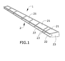
- Figure 1 shows a trailing edge of the state of the art.
- the known trailing edge comprises, as previously explained in the background of the invention:
- the trailing edge of the claimed invention comprises the integrated main structure and the set of removable sandwich type lower panels (22) attached to the integrated main structure.
- the integrated main structure comprises the upper cover (1), the lower flanges, and the set of ribs (23) extending between the upper cover (1) and the lower flanges while the removable sandwich lower panels (22) are attached to said lower flanges.
- the tool module (7) of the invention comprises an upper part having a hollow (9) for accommodating the sandwich core (5).
- a prepreg laminate is formed over the tool module (7) configuring a double C-shaped laminated preform (10) having an upper section (15) with a recess (16) corresponding with the hollow (9) of the tool module (7), two primary flanges (3) and two secondary flanges (8).
- the upper section (15) will configure part of the upper cover (1) of the trailing edge
- the two primary flanges (3) will configure part of the ribs (23)
- the two secondary flanges (8) will configure the lower flange of the trailing edge.
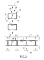
- Figure 2 shows an embodiment of the process of the manufacturing method of the invention.
- a first flat laminate (17) is provided and located over the tool module (7); said flat laminate (17) can be compacted during lay-up.
- the forming process configures the double C shape and also its recess (16) by for instance a hot-forming or a press-forming process.
- a second embodiment would be directly shaping the laminate against the tool module (7).
- two different methods are possible, by an automatic tape laying machine (ATL) or by means of fiber placement.
- ATL automatic tape laying machine
- Fiber placement allows directly shaping over the tool module (7) both, the recess (16) and the double C shape. Fiber placement allows bigger slopes in the recess (16) therefore said recess (16) can be directly taped by fiber placement.
- ATL automatic tape laying machines
- the recess (16) and the double C shape might have to be formed by a forming process, ie, hot forming or press-forming.
- ATL allows directly shaping the upper section (15) over the tool module (7) and afterwards forming the double C shape. Therefore a flat laminate (17) is layed up onto the upper section (15) of the tool module (7) by an automatic tape laying machine to obtain a flat laminate with the shape of the recess (16) and by then applying a forming process in order to achieve the double C shape.
- the upper section (15) can be made with the shape of the hollow (9) and, for instance, during the hot forming of the double C shape, finishing the formation of the recess (16) with a male tool (13) or air ports (14), as it will be explained below, to make sure that the recess (16) follows the shape of the hollow (9).
- Previously shaping the laminate with the shape of the hollow (9) and afterwards finishing the recess (16) is more effective than fully forming the recess (16).
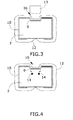
- Figure 3 shows an embodiment in which during the forming process a membrane (12) is located over the tool module (7) and said membrane (12) is pressed against the tool module (7) by means of vacuum, for instance, provided by a general air port.
- a male tool (13) presses the prepreg laminate against the hollow (9) of the tool module (7) for forming the recess (16) or finishing said recess (16) in case the upper section (15) had previously been made with the shape of the hollow (9).
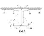
- Figure 4 shows a different embodiment for forming the recess (16) of the double C-shaped laminated preform (10).
- Said embodiment comprises at least two air ports (14) located close to the hollow (9) of the tool module (7) therefore located close to the target area.
- the male tool (13) is not needed due to said location of the two air ports (14) close to the inner corners of the hollow (9).
- the sandwich core (5) is positioned into the recess (16) of the upper section (15) of the double C-shaped preform (10).
- Figure 2 also shows that before providing the further prepreg laminate (4), rovings (6) are provided into the joints of two double C-shape laminated preforms (10) of two adjacent tool modules (7).
- the manufacturing of the rovings (6) can be manually or automatically.
- the rovings (6) are used to fill up the space in the radii that are created between adjacent primary flanges (3).
- lower prepreg laminates (11) are provided against two consecutives secondary flanges (8).
- the lower panels (22), which are removable, will be joined to the secondary flanges (8) and the lower prepreg laminates (11).
- a further prepreg laminate (4) is provided on top of the aligned set of tool modules (7) and finally a curing process is applied to cocured said laminated preforms so that the integrated trailing edge main structure is formed.
- the double C-shaped preform (10) is thicker adjacent to the corners between the primary flanges (3) and the upper section (15), the primary flanges (3) and the secondary flanges (8) and along the primary flanges (3). This is due to the fact that ribs (23) are required to have a bigger thickness for their higher structural demand.
- Figure 5 shows a thickness change (18) located in the proximity of the corner between the primary flanges (3) and the upper section (15), said thickness change (18) corresponds to the transition between the thickness of the upper section (15) and of the ribs (23).
- the same tool modules (7) are finally cured together.
- the tool modules (7) consist of modules that will compose a puzzle in order to create the right compaction parameters.
- the demoulding of the kit must be performed carefully avoiding any damage to the structure. As the trailing edge has got a conical shape, the demoulding must be performed oriented to the front direction which is the HTP RS direction.
- the tool modules (7) can be made of aluminium which helps the demoulding process thanks to the thermal contraction. A single approach could be a demoulding to the RS direction. But due to the complexity that the sandwich core (5) involves related to the thickness change in the upper cover (1) it is more practical to divide the tooling to ease the demoulding process.
- a Z shape profile can be riveted to the structure. They are placed at the rear end of the top panel to improve their buckling behavior.
Landscapes
- Engineering & Computer Science (AREA)
- Mechanical Engineering (AREA)
- Chemical & Material Sciences (AREA)
- Composite Materials (AREA)
- Aviation & Aerospace Engineering (AREA)
- Civil Engineering (AREA)
- Structural Engineering (AREA)
- Architecture (AREA)
- Physics & Mathematics (AREA)
- Fluid Mechanics (AREA)
- Robotics (AREA)
- Moulding By Coating Moulds (AREA)
- Casting Or Compression Moulding Of Plastics Or The Like (AREA)
Abstract
- an integrated main structure comprising:
○ an upper cover (1),
○ lower flanges, and
○ a set of ribs (23) extending between the upper cover (1) and the lower flanges,
- a set of sandwich type lower panels (22) attachable to the lower flanges of the integrated main structure.
Description
- The present invention refers to an integrated composite trailing edge and to its manufacturing method.
- In the past, aircraft were most or totally built up by metallic components, providing a good performance in terms of mechanical behavior but, as a drawback, they are penalized in terms of weight.
- One of the most important solutions was the use of composite fiber reinforced polymers (CFRP) for major structural parts, achieving an important weight savings and cost operations decrease.
- Composites have been demonstrated to fulfill the following requirements:
- Weight savings.
- Be cost effective.
- Meet structural requisite under aircraft conditions.
- Beneficial cost/weight relation.
- Horizontal tail plane (HTP) is a structure consisting of a center structural box section, called torsion box and two outer sections, the forward section known as leading edge and the rearward section known as trailing edge.
- Trailing edges are the transition between the torsion box and the control surfaces. Trailing edges usually comprise an upper cover and a lower cover, both formed by a set of panels.
- These panels are sandwich type panels. Standard architecture is also composed of a set of ribs extending between the upper cover and the lower cover. These ribs are of two kinds, bearing ribs and trailing edge ribs. Trailing edge ribs are optional and therefore a trailing edge without these ribs is possible. Bearing ribs hold the hinge line of the control surfaces while trailing edge ribs are used to provide stability to the trailing edge structure.
- Upper panels are joined to the ribs by means of rivets while lower panels are joined by means of screws to a lower flange of the ribs, so the panels which make up the lower cover can be opened to gain access for maintance tasks of elements such as systems, actuators or fittings.
- A known method for manufacturing said elements uses prepreg technology. Each of the different components is manufactured separately, including lay-up, forming and curing processes, afterwards they are assembled together and joined by means of rivets.
- Drawbacks of the known structure are the weight of the rivets used to join the different components and the amount of time needed for the assembly process due to the fact that it includes not only providing a large number of elements but also the need to link these elements together.
- The above mentioned drawbacks are solved by the claimed method and trailing edge which provides advantages in terms of manufacturing and assembly.
- The trailing edge of the claimed invention comprises an integrated main structure and a set of removable sandwich type lower panels attached to the integrated main structure. The integrated main structure comprises an upper cover, lower flanges, and a set of ribs extending between the upper cover and said lower flanges while the removable lower panels are attached to said lower flanges.
- The claimed method comprises the following steps:
- Providing a set of prepreg laminated preforms of composite material over a set of tool modules, said tool modules having a hollow located at their upper part for receiving a sandwich core. The tool modules are configured so that each prepreg laminated perform configures a double C-shaped laminated preform having an upper section with a recess corresponding with the hollow, two primary flanges and two secondary flanges. The upper section is configured for partly forming a segment of the upper cover of the integrated main structure, the two primary flanges are configured for partly forming the ribs and the two secondary flanges are configured for forming the lower flanges of the integrated main structure.
- Providing a set of sandwich cores into the recesses of the double C-shaped laminated preforms.
- Aligning the set of tool modules so that adjacent primary flanges are located together.
- Providing rovings to fill up the space in the radii between adjacent primary flanges.
- Providing a prepreg laminate on top of the aligned set of tool modules.
- Providing lower prepreg laminates against two consecutive secondary flanges.
- Applying a curing process to cocure said laminated preforms so that the integrated main structure of the trailing edge is formed.
- The prepreg laminates of composite material can be a flat laminate manufactured by means of manual or automatic lay-up followed by the forming process of the double C-shaped laminated preforms and its recesses by for instance a hot-forming or a press-forming process. In other embodiment the composite material can be directly shaped on the tool module by for example a fiber placement process obtaining the double C shape and the recess for receiving the sandwich core.
- The term "laminated preform" as used in this specification designates a composite item that requires an individual forming process such as hot-forming, press-forming, to form it with certain characteristics and that is intended to be integrated with other elements in the manufacturing process of the product to which it belongs. As previously stated the laminated preforms can also be made directly with the final shape by means of an automatic fiber placement machine, locating the carbon fiber over the curing tooling which will be integrated with the whole set.
- An important aspect of the present invention is that each laminated preform partially forms various components of a trailing edge known in the state of the art. As previously stated, each laminated preform forms part of the upper cover, part of a rib and part of a lower flange forming the lower cover. Moreover, each component of a traditional trailing edge is formed from several laminated performs, for instance, a rib is formed by joining two primary flanges of two laminated performs.
- The main advantage of the claimed method over conventional methods is based on the reduction of the manufacturing and assembly operations, because thanks to the claimed method a single curing step is applied to the whole piece contrary to independently curing every part. Another advantage is that it is possible to obtain the piece without the need of rivets between ribs and covers. This will also reduce weight due to the elimination of these mechanical bonds. This leads to high and optimum integration of the trailing edge and to a reduction of costs and weight, increasing or maintaining its structural characteristics.
- Therefore, said method not only reduces the assembly process but also the manufacturing process and more specifically the manufacturing and assembly steps closed to the final steps of manufacturing and assembly. Additionally the same tool module is used throughout the whole manufacturing process.
- It has to be taken into account that the lower cover and its panels must be removable for inspection and it is manufactured as known in the state of the art. In fact, the integrated structure object of the invention splits fixed parts, for instance, ribs, upper cover from removable parts such as lower covers.
- It is also an object of the present invention an aircraft composite trailing edge comprising an integrated main structure and a set of removable sandwich type lower panels attached to the integrated main structure. The integrated main structure comprises an upper cover, lower flanges, and a set of ribs extending between the upper cover and said lower flanges while the removable lower panels are attached to said lower flanges.
- The composite trailing edge also comprises:
- a set of double C-shaped laminated preforms made of prepreg laminate preforms of composite material having an upper section with a recess, two primary flanges and two secondary flanges, the upper section configured for partly forming a segment of the upper cover of the integrated main structure, the two primary flanges configured for partly forming the ribs and the two secondary flanges configured for forming the lower flanges of the integrated main structure,
- the set of double C-shaped laminated preforms located aligned such that adjacent primary flanges are located together,
- a set of rovings located to fill up the space in the radii between adjacent primary flanges,
- a prepreg laminate located on top of the set of double C-shaped preforms,
- a set of sandwich cores located into the recesses of the double C-shaped laminated preforms,
- lower prepreg laminates located against two consecutive secondary flanges,
- the set of double C-shaped laminated preforms, the prepeg laminate and the sandwich cores forming an integrated structure manufactured by the previously described method.
- To complete the description and in order to provide for a better understanding of the invention, a set of drawings is provided. Said drawings form an integral part of the description and illustrate preferred embodiments of the invention. The drawings comprises the following figures:
-
Figure 1 is a schematic perspective view of a trailing edge of the state of the art. -
Figure 2 is a schematic manufacturing process of an embodiment of the invention. -
Figure 3 is a schematic manufacturing process of an embodiment for forming the laminated preforms, including the primary and secondary flanges and the recess. -
Figure 4 is another embodiment of the manufacturing process for forming the laminated preforms, including the primary and secondary flanges and the recess. -
Figure 5 is a schematic view of two adjacent primary flanges, secondary flanges and upper sections. -
Figure 1 shows a trailing edge of the state of the art. The known trailing edge comprises, as previously explained in the background of the invention: - an upper cover (1) formed by a set of sandwich type upper panels (21),
- a lower cover (2) formed by a set of sandwich type lower panels (22),
- a set of transversal ribs (23) extending between the upper and the lower covers (1, 2).
- In contrast, the trailing edge of the claimed invention comprises the integrated main structure and the set of removable sandwich type lower panels (22) attached to the integrated main structure. The integrated main structure comprises the upper cover (1), the lower flanges, and the set of ribs (23) extending between the upper cover (1) and the lower flanges while the removable sandwich lower panels (22) are attached to said lower flanges.
- The tool module (7) of the invention comprises an upper part having a hollow (9) for accommodating the sandwich core (5). A prepreg laminate is formed over the tool module (7) configuring a double C-shaped laminated preform (10) having an upper section (15) with a recess (16) corresponding with the hollow (9) of the tool module (7), two primary flanges (3) and two secondary flanges (8). The upper section (15) will configure part of the upper cover (1) of the trailing edge, the two primary flanges (3) will configure part of the ribs (23) and the two secondary flanges (8) will configure the lower flange of the trailing edge.
- For forming the double C-shaped preforms (10) and the recesses (16) for accommodating the sandwich core (5) two different embodiments are possible.
Figure 2 shows an embodiment of the process of the manufacturing method of the invention. A first flat laminate (17) is provided and located over the tool module (7); said flat laminate (17) can be compacted during lay-up. The forming process configures the double C shape and also its recess (16) by for instance a hot-forming or a press-forming process. - A second embodiment would be directly shaping the laminate against the tool module (7). In this second embodiment, two different methods are possible, by an automatic tape laying machine (ATL) or by means of fiber placement.
- Fiber placement allows directly shaping over the tool module (7) both, the recess (16) and the double C shape. Fiber placement allows bigger slopes in the recess (16) therefore said recess (16) can be directly taped by fiber placement.
- To the contrary, automatic tape laying machines (ATL) have limits on slopes that can be taped therefore the recess (16) and the double C shape might have to be formed by a forming process, ie, hot forming or press-forming. ATL allows directly shaping the upper section (15) over the tool module (7) and afterwards forming the double C shape. Therefore a flat laminate (17) is layed up onto the upper section (15) of the tool module (7) by an automatic tape laying machine to obtain a flat laminate with the shape of the recess (16) and by then applying a forming process in order to achieve the double C shape.
- To ensure good compactation in the area of the hollow (9), the upper section (15) can be made with the shape of the hollow (9) and, for instance, during the hot forming of the double C shape, finishing the formation of the recess (16) with a male tool (13) or air ports (14), as it will be explained below, to make sure that the recess (16) follows the shape of the hollow (9). Previously shaping the laminate with the shape of the hollow (9) and afterwards finishing the recess (16) is more effective than fully forming the recess (16).
- Forming this type of double-C shaped preform (10) is not known because in addition to said double-C shaped preform (10) a recess (16) has to be formed which is a more complex task due to the sharp inner corners of the hollow (9), because the laminate has to accurately follow the shape of the tool module (7).
-
Figure 3 shows an embodiment in which during the forming process a membrane (12) is located over the tool module (7) and said membrane (12) is pressed against the tool module (7) by means of vacuum, for instance, provided by a general air port. A male tool (13) presses the prepreg laminate against the hollow (9) of the tool module (7) for forming the recess (16) or finishing said recess (16) in case the upper section (15) had previously been made with the shape of the hollow (9). -
Figure 4 shows a different embodiment for forming the recess (16) of the double C-shaped laminated preform (10). Said embodiment comprises at least two air ports (14) located close to the hollow (9) of the tool module (7) therefore located close to the target area. In that second embodiment the male tool (13) is not needed due to said location of the two air ports (14) close to the inner corners of the hollow (9). - After providing the double C-shaped preform (10) over the tool modules (7), the sandwich core (5) is positioned into the recess (16) of the upper section (15) of the double C-shaped preform (10).
- Following the deposition of the sandwich core (5), all the double C-shaped laminated preforms (10) and their corresponding tool modules (7) are aligned together so that primary flanges (3) of adjacent preforms are located against each other. Two adjacent primary flanges (3) will configure a rib (23) of the trailing edge.
- Additionally,
Figure 2 also shows that before providing the further prepreg laminate (4), rovings (6) are provided into the joints of two double C-shape laminated preforms (10) of two adjacent tool modules (7). The manufacturing of the rovings (6) can be manually or automatically. The rovings (6) are used to fill up the space in the radii that are created between adjacent primary flanges (3). Before the curing process, lower prepreg laminates (11) are provided against two consecutives secondary flanges (8). The lower panels (22), which are removable, will be joined to the secondary flanges (8) and the lower prepreg laminates (11). - A further prepreg laminate (4) is provided on top of the aligned set of tool modules (7) and finally a curing process is applied to cocured said laminated preforms so that the integrated trailing edge main structure is formed.
- The double C-shaped preform (10) is thicker adjacent to the corners between the primary flanges (3) and the upper section (15), the primary flanges (3) and the secondary flanges (8) and along the primary flanges (3). This is due to the fact that ribs (23) are required to have a bigger thickness for their higher structural demand.
Figure 5 shows a thickness change (18) located in the proximity of the corner between the primary flanges (3) and the upper section (15), said thickness change (18) corresponds to the transition between the thickness of the upper section (15) and of the ribs (23). - The same tool modules (7) are finally cured together. The tool modules (7) consist of modules that will compose a puzzle in order to create the right compaction parameters.
- The demoulding of the kit must be performed carefully avoiding any damage to the structure. As the trailing edge has got a conical shape, the demoulding must be performed oriented to the front direction which is the HTP RS direction. In addition, the tool modules (7) can be made of aluminium which helps the demoulding process thanks to the thermal contraction. A single approach could be a demoulding to the RS direction. But due to the complexity that the sandwich core (5) involves related to the thickness change in the upper cover (1) it is more practical to divide the tooling to ease the demoulding process.
- To improve the buckling behavior of the panels, a Z shape profile can be riveted to the structure. They are placed at the rear end of the top panel to improve their buckling behavior.
Claims (13)
- Method for manufacturing an integrated composite trailing edge of an aircraft, the trailing edge comprising:- an integrated main structure comprising:○ an upper cover (1),○ lower flanges, and○ a set of ribs (23) extending between the upper cover (1) and the lower flanges,- a set of sandwich type lower panels (22) attachable to the lower flanges of the integrated main structure,the method characterized in that it comprises the following steps:a) providing a set of prepreg laminated preforms of composite material over a set of tool modules (7), said tool modules (7) having a hollow (9) located at their upper part for receiving a sandwich core (5), the tool modules (7) being configured so that each prepreg laminated perform configures a double C-shaped laminated preform (10) having an upper section (15) with a recess (16) corresponding with the hollow (9), two primary flanges (3) and two secondary flanges (8), the upper section (15) configured for partly forming a segment of the upper cover (1) of the integrated main structure, the two primary flanges (3) configured for partly forming the ribs (23) and the two secondary flanges (8) configured for forming the lower flanges of the integrated main structure,b) providing a set of sandwich cores (5) into the recesses (16) of the double C-shaped laminated preforms (10),c) aligning the set of tool modules (7) so that adjacent primary flanges (3) are located together,d) providing rovings (6) to fill up the space in the radii between adjacent primary flanges (3),e) providing a prepreg laminate (4) on top of the aligned set of tool modules (7),f) providing lower prepreg laminates (11) against two consecutive secondary flanges (8), andg) applying a curing process to cocure said laminated preforms so that the integrated main structure of the trailing edge is formed.
- Method according to claim 1, wherein the double C-shaped laminated preform is formed by providing a flat prepreg laminate (17) over the tool module (7) followed by a forming process of said flat laminate (17) over the tool module (7) for forming the double C shape and the recess (16).
- Method according to claim 2, wherein during the forming process a membrane (12) is located over the tool module (7) being pressed against the tool module (7) by means of the vacuum provided by a general air port while a male tool (13) presses the flat prepreg laminate (17) against the hollow (9) of the tool module (7) for forming the recess (16) of the C-shaped laminated preform (10).
- Method according to claim 2, wherein during the forming process a membrane (12) is located over the tool module (7), the membrane (12) being pressed against the tool module (7) for forming the recess (16) of the C-shaped laminated preform (10) by means of the vacuum provided by at least two air ports (14) located in the proximity of the hollow (9).
- Method according to claim 4, wherein the two air ports (14) are located in the proximity of each of the inner corners of the hollow (9).
- Method according to claim 1, wherein the double C-shaped laminated preform is formed by lying up a flat prepreg laminate (17) onto the upper section (15) of the tool module (7) by an automatic tape laying machine to obtain a flat laminate with the shape of the recess (16) and by then applying a forming process in order to achieve the double C shape.
- Method according to claim 6, wherein during the forming process the recess (16) is finished by positioning a membrane (12) over the tool module (7) the membrane (12) being pressed against the tool module (7) by means of the vacuum provided by at least two air ports (14) located in the proximity of the hollow (9).
- Method according to claim 7, wherein the two air ports (14) are located in the proximity of each of the inner corners of the hollow (9).
- Method according to claim 6, wherein during the forming process the recess (16) is finished by positioning a membrane (12) over the tool module (7) the membrane (12) being pressed against the tool module (7) by means of the vacuum provided by an air port and by pressing a male tool (13) against the hollow (9) of the tool module (7).
- Method according to claim 1, wherein the double C-shaped prepreg laminated preform (10) and its recess (16) are formed by directly laying up a laminate over the tool module (7) by means of a fiber placement machine.
- Aircraft integrated composite trailing edge characterized in that it comprises:- an integrated main structure comprising:○ an upper cover (1),○ lower flanges, and○ a set of ribs (23) extending between the upper cover (1) and the lower flanges,- a set of sandwich type lower panels (22) attachable to the lower flanges of the integrated main structure,- a set of double C-shaped laminated preforms (10) made of prepreg laminate preforms of composite material having an upper section (15) with a recess (16), two primary flanges (3) and two secondary flanges (8), the upper section (15) configured for partly forming a segment of the upper cover (1) of the integrated main structure, the two primary flanges (3) configured for partly forming the ribs (23) and the two secondary flanges (8) configured for forming the lower flanges of the integrated main structure,- the set of double C-shaped laminated preforms (10) located aligned such that adjacent primary flanges (3) are located together,- a prepreg laminate (4) located on top of the set of double C-shaped preforms (10),- a set of sandwich cores (5) located into the recesses (16) of the double C-shaped laminated preforms (10),- a set of rovings (6) located to fill up the space in the radii between adjacent primary flanges (3),- lower prepreg laminates (11) located against two consecutive secondary flanges (8),- the set of double C-shaped laminated preforms (10), the prepeg laminate (4) and the sandwich cores (5) forming an integrated structure manufactured by the method according to claims 1-6.
- Aircraft integrated composite trailing edge, according to claim 11, wherein double C-shaped laminated preforms (10) are thicker adjacent to the corner between the primary flanges (3) and the secondary flanges (8), between the primary flanges (3) and the upper section (15) and along the primary flanges (3).
- Aircraft, comprising a trailing edge according to any preceding claim 11 or 12.
Priority Applications (4)
| Application Number | Priority Date | Filing Date | Title |
|---|---|---|---|
| ES13382482.1T ES2691962T3 (en) | 2013-11-28 | 2013-11-28 | Method for manufacturing an integrated trailing edge of composite material |
| EP13382482.1A EP2878435B1 (en) | 2013-11-28 | 2013-11-28 | Method for manufacturing an integrated composite trailing edge |
| US14/551,589 US9522504B2 (en) | 2013-11-28 | 2014-11-24 | Method for manufacturing an integrated composite trailing edge and integrated composite trailing edge |
| CN201410858318.3A CN104670475B (en) | 2013-11-28 | 2014-11-28 | Integrated composite wing rear and its manufacturing method |
Applications Claiming Priority (1)
| Application Number | Priority Date | Filing Date | Title |
|---|---|---|---|
| EP13382482.1A EP2878435B1 (en) | 2013-11-28 | 2013-11-28 | Method for manufacturing an integrated composite trailing edge |
Publications (2)
| Publication Number | Publication Date |
|---|---|
| EP2878435A1 true EP2878435A1 (en) | 2015-06-03 |
| EP2878435B1 EP2878435B1 (en) | 2018-07-18 |
Family
ID=49753111
Family Applications (1)
| Application Number | Title | Priority Date | Filing Date |
|---|---|---|---|
| EP13382482.1A Active EP2878435B1 (en) | 2013-11-28 | 2013-11-28 | Method for manufacturing an integrated composite trailing edge |
Country Status (4)
| Country | Link |
|---|---|
| US (1) | US9522504B2 (en) |
| EP (1) | EP2878435B1 (en) |
| CN (1) | CN104670475B (en) |
| ES (1) | ES2691962T3 (en) |
Cited By (4)
| Publication number | Priority date | Publication date | Assignee | Title |
|---|---|---|---|---|
| EP3590824A1 (en) | 2018-07-06 | 2020-01-08 | Airbus Operations, S.L. | Method for manufacturing the trailing edge ribs and the bearing ribs of trailing edges of aircraft lifting surfaces |
| EP3597525A1 (en) * | 2018-07-19 | 2020-01-22 | Airbus Operations, S.L.U. | Curved composite part and manufacturing method thereof |
| EP3885106A1 (en) * | 2020-03-25 | 2021-09-29 | Airbus Operations, S.L.U. | Method for manufacturing a part |
| EP4186783A1 (en) * | 2021-11-24 | 2023-05-31 | Airbus Operations, S.L.U. | Manufacturing method of a control surface of an aircraft and aircraft control surface |
Families Citing this family (10)
| Publication number | Priority date | Publication date | Assignee | Title |
|---|---|---|---|---|
| US10329030B2 (en) * | 2016-03-04 | 2019-06-25 | The Boeing Company | Conductive radius filler system and method |
| CN108177360B (en) * | 2017-12-25 | 2024-07-05 | 航天神舟飞行器有限公司 | Forming tool and forming method for integral wall plate of unmanned aerial vehicle composite wing |
| US11407165B2 (en) | 2019-01-15 | 2022-08-09 | Hamilton Sundstrand Corporation | Methods of making components |
| CN110450937B (en) * | 2019-08-23 | 2020-12-04 | 中国商用飞机有限责任公司北京民用飞机技术研究中心 | Composite material "I" type long truss wall plate structure, forming mold and forming method |
| US11572152B2 (en) | 2020-05-21 | 2023-02-07 | The Boeing Company | Structural composite airfoils with a single spar, and related methods |
| US11401026B2 (en) | 2020-05-21 | 2022-08-02 | The Boeing Company | Structural composite airfoils with a single spar, and related methods |
| US11453476B2 (en) | 2020-05-21 | 2022-09-27 | The Boeing Company | Structural composite airfoils with an improved leading edge, and related methods |
| US11554848B2 (en) | 2020-05-21 | 2023-01-17 | The Boeing Company | Structural composite airfoils with a single spar, and related methods |
| CN114771802A (en) | 2021-01-22 | 2022-07-22 | 波音公司 | Aerodynamic structure and method of forming an aerodynamic structure |
| CN115519806A (en) * | 2022-08-17 | 2022-12-27 | 长春长光宇航复合材料有限公司 | Forming mold and forming method for composite material compartment with reinforced longitudinal ring belt |
Citations (2)
| Publication number | Priority date | Publication date | Assignee | Title |
|---|---|---|---|---|
| FR2946009A1 (en) * | 2009-05-28 | 2010-12-03 | Lorraine De Construction Aeron | Composite structuring panel for trailing edge of an aircraft element, comprises an upper surface, a lower surface, and an edge connecting the upper and lower surfaces, where upper and lower surfaces are connected by transverse stiffeners |
| WO2012007780A1 (en) * | 2010-07-13 | 2012-01-19 | Learjet Inc. | Composite structure and method of forming same |
Family Cites Families (15)
| Publication number | Priority date | Publication date | Assignee | Title |
|---|---|---|---|---|
| US3028292A (en) * | 1957-05-27 | 1962-04-03 | Parsons Corp | Method of manufacturing plastic rotor blades |
| US4053667A (en) * | 1974-09-09 | 1977-10-11 | Lockheed Aircraft Corporation | Stiffened structural laminate and method of molding laminate with stiffener beads |
| DE3341564A1 (en) * | 1983-11-17 | 1985-05-30 | Messerschmitt-Bölkow-Blohm GmbH, 8012 Ottobrunn | CURVED AREA COMPONENT, ESPECIALLY FOR AIRCRAFT AND DEVICE FOR THEIR PRODUCTION |
| US4475976A (en) * | 1983-12-23 | 1984-10-09 | The Boeing Company | Method and apparatus for forming composite material articles |
| US5108532A (en) * | 1988-02-02 | 1992-04-28 | Northrop Corporation | Method and apparatus for shaping, forming, consolidating and co-consolidating thermoplastic or thermosetting composite products |
| CA2056330C (en) * | 1990-12-19 | 2003-06-10 | Alexander C. Dublinski | Method of fabricating a complex part made of composite material |
| US5490472A (en) * | 1993-10-14 | 1996-02-13 | Isomat, Inc. | Carbon fiber spar and method of making |
| US5547629A (en) * | 1994-09-27 | 1996-08-20 | Competition Composites, Inc. | Method for manufacturing a one-piece molded composite airfoil |
| US5817269A (en) * | 1996-10-25 | 1998-10-06 | The Boeing Company | Composite fabrication method and tooling to improve part consolidation |
| US6231941B1 (en) * | 1998-07-14 | 2001-05-15 | The Boeing Company | Radius fillers for a resin transfer molding process |
| JP4316059B2 (en) * | 1999-08-06 | 2009-08-19 | 富士重工業株式会社 | Manufacturing method of composite wing |
| AU2001262912A1 (en) * | 2000-02-25 | 2001-09-03 | The Boeing Company | Laminated composite radius filler |
| CN102427999B (en) * | 2009-05-28 | 2015-11-25 | 洛林航空工程公司 | Composite structural panel for trailing edge of aircraft element and method of manufacturing same |
| CN101749194B (en) * | 2009-12-11 | 2011-09-14 | 重庆通用工业(集团)有限责任公司 | Wind turbine blade for large-scale wind generating set, and molding method thereof |
| US20130154154A1 (en) * | 2011-06-27 | 2013-06-20 | William L. Rodman | Composite structures having cored members |
-
2013
- 2013-11-28 EP EP13382482.1A patent/EP2878435B1/en active Active
- 2013-11-28 ES ES13382482.1T patent/ES2691962T3/en active Active
-
2014
- 2014-11-24 US US14/551,589 patent/US9522504B2/en active Active
- 2014-11-28 CN CN201410858318.3A patent/CN104670475B/en active Active
Patent Citations (2)
| Publication number | Priority date | Publication date | Assignee | Title |
|---|---|---|---|---|
| FR2946009A1 (en) * | 2009-05-28 | 2010-12-03 | Lorraine De Construction Aeron | Composite structuring panel for trailing edge of an aircraft element, comprises an upper surface, a lower surface, and an edge connecting the upper and lower surfaces, where upper and lower surfaces are connected by transverse stiffeners |
| WO2012007780A1 (en) * | 2010-07-13 | 2012-01-19 | Learjet Inc. | Composite structure and method of forming same |
Cited By (6)
| Publication number | Priority date | Publication date | Assignee | Title |
|---|---|---|---|---|
| EP3590824A1 (en) | 2018-07-06 | 2020-01-08 | Airbus Operations, S.L. | Method for manufacturing the trailing edge ribs and the bearing ribs of trailing edges of aircraft lifting surfaces |
| US11643222B2 (en) | 2018-07-06 | 2023-05-09 | Airbus Operations S.L. | Method for manufacturing the trailing edge ribs and the bearing ribs of trailing edges of aircraft lifting surfaces |
| EP3597525A1 (en) * | 2018-07-19 | 2020-01-22 | Airbus Operations, S.L.U. | Curved composite part and manufacturing method thereof |
| EP3885106A1 (en) * | 2020-03-25 | 2021-09-29 | Airbus Operations, S.L.U. | Method for manufacturing a part |
| EP4186783A1 (en) * | 2021-11-24 | 2023-05-31 | Airbus Operations, S.L.U. | Manufacturing method of a control surface of an aircraft and aircraft control surface |
| US12006064B2 (en) | 2021-11-24 | 2024-06-11 | Airbus Operations S.L.U. | Manufacturing method of a control surface of an aircraft and aircraft control surface |
Also Published As
| Publication number | Publication date |
|---|---|
| US9522504B2 (en) | 2016-12-20 |
| ES2691962T3 (en) | 2018-11-29 |
| US20150144737A1 (en) | 2015-05-28 |
| CN104670475A (en) | 2015-06-03 |
| CN104670475B (en) | 2018-10-19 |
| EP2878435B1 (en) | 2018-07-18 |
Similar Documents
| Publication | Publication Date | Title |
|---|---|---|
| US9522504B2 (en) | Method for manufacturing an integrated composite trailing edge and integrated composite trailing edge | |
| US7806367B2 (en) | Integrated multispar torsion box of composite material | |
| US9669581B2 (en) | Method for manufacturing an aeronautical torsion box, torsion box and tool for manufacturing an aeronautical torsion box | |
| CN103832574B (en) | Torsion box for the optimization of ROV | |
| EP2301840A2 (en) | Integrated aircraft structure in composite material | |
| CN103832576B (en) | Include the high integrity structure of leading edge rib and trailing edge rib for ROV lifting surface | |
| CN105035359B (en) | A structure and processing method of integrally formed rudder surface of composite material with decreasing stiffness | |
| US11220354B2 (en) | Composite fuselage assembly and methods to form the assembly | |
| EP2318466B1 (en) | Method for manufacturing a composite structure and intermediate composite structure | |
| US9051062B1 (en) | Assembly using skeleton structure | |
| US9649820B1 (en) | Assembly using skeleton structure | |
| CN103448901A (en) | Bonded composite airfoil and fabrication method | |
| US20120282430A1 (en) | Composite material part with large variation in thickness | |
| CN103587677B (en) | The highly integrated internal structure of the torsion box of aircraft lifting surfaces | |
| US8524022B2 (en) | Method of manufacturing a structure | |
| US8578609B2 (en) | Manufacturing procedure of a part made out of a composite material introducing a geometric change in one of its faces | |
| US11577816B2 (en) | Composite laminate for an airframe lifting surface and method for manufacturing thereof | |
| CN211543866U (en) | Composite material partition frame structure for aircraft wing trailing edge | |
| JP2022105979A (en) | Composite spars with integrated sacrificial surfaces | |
| CN113173255A (en) | Modular tool, method for assembling a tool set and aircraft | |
| CN218751450U (en) | Mould is spread to structural framework in cabin | |
| US20130264002A1 (en) | Integral stiffener |
Legal Events
| Date | Code | Title | Description |
|---|---|---|---|
| PUAI | Public reference made under article 153(3) epc to a published international application that has entered the european phase |
Free format text: ORIGINAL CODE: 0009012 |
|
| 17P | Request for examination filed |
Effective date: 20131128 |
|
| AK | Designated contracting states |
Kind code of ref document: A1 Designated state(s): AL AT BE BG CH CY CZ DE DK EE ES FI FR GB GR HR HU IE IS IT LI LT LU LV MC MK MT NL NO PL PT RO RS SE SI SK SM TR |
|
| AX | Request for extension of the european patent |
Extension state: BA ME |
|
| R17P | Request for examination filed (corrected) |
Effective date: 20151104 |
|
| RBV | Designated contracting states (corrected) |
Designated state(s): AL AT BE BG CH CY CZ DE DK EE ES FI FR GB GR HR HU IE IS IT LI LT LU LV MC MK MT NL NO PL PT RO RS SE SI SK SM TR |
|
| 17Q | First examination report despatched |
Effective date: 20160519 |
|
| RIC1 | Information provided on ipc code assigned before grant |
Ipc: B32B 37/16 20060101ALI20171219BHEP Ipc: B29C 70/30 20060101ALI20171219BHEP Ipc: B29L 31/30 20060101ALN20171219BHEP Ipc: B29C 70/34 20060101ALI20171219BHEP Ipc: B32B 37/10 20060101ALI20171219BHEP Ipc: B29C 70/38 20060101ALN20171219BHEP Ipc: B64C 3/28 20060101ALI20171219BHEP Ipc: B29C 70/08 20060101ALI20171219BHEP Ipc: B29C 70/86 20060101AFI20171219BHEP Ipc: B29D 99/00 20100101ALI20171219BHEP Ipc: B29C 70/54 20060101ALI20171219BHEP |
|
| GRAP | Despatch of communication of intention to grant a patent |
Free format text: ORIGINAL CODE: EPIDOSNIGR1 |
|
| STAA | Information on the status of an ep patent application or granted ep patent |
Free format text: STATUS: GRANT OF PATENT IS INTENDED |
|
| INTG | Intention to grant announced |
Effective date: 20180209 |
|
| RIC1 | Information provided on ipc code assigned before grant |
Ipc: B29C 70/34 20060101ALI20180129BHEP Ipc: B32B 37/10 20060101ALI20180129BHEP Ipc: B29C 70/38 20060101ALN20180129BHEP Ipc: B29L 31/30 20060101ALN20180129BHEP Ipc: B29C 70/54 20060101ALI20180129BHEP Ipc: B64C 3/28 20060101ALI20180129BHEP Ipc: B29C 70/08 20060101ALI20180129BHEP Ipc: B29C 70/86 20060101AFI20180129BHEP Ipc: B32B 37/16 20060101ALI20180129BHEP Ipc: B29C 70/30 20060101ALI20180129BHEP Ipc: B29D 99/00 20100101ALI20180129BHEP |
|
| GRAS | Grant fee paid |
Free format text: ORIGINAL CODE: EPIDOSNIGR3 |
|
| GRAA | (expected) grant |
Free format text: ORIGINAL CODE: 0009210 |
|
| STAA | Information on the status of an ep patent application or granted ep patent |
Free format text: STATUS: THE PATENT HAS BEEN GRANTED |
|
| AK | Designated contracting states |
Kind code of ref document: B1 Designated state(s): AL AT BE BG CH CY CZ DE DK EE ES FI FR GB GR HR HU IE IS IT LI LT LU LV MC MK MT NL NO PL PT RO RS SE SI SK SM TR |
|
| REG | Reference to a national code |
Ref country code: GB Ref legal event code: FG4D |
|
| REG | Reference to a national code |
Ref country code: CH Ref legal event code: EP |
|
| REG | Reference to a national code |
Ref country code: IE Ref legal event code: FG4D |
|
| REG | Reference to a national code |
Ref country code: AT Ref legal event code: REF Ref document number: 1018902 Country of ref document: AT Kind code of ref document: T Effective date: 20180815 |
|
| REG | Reference to a national code |
Ref country code: DE Ref legal event code: R096 Ref document number: 602013040385 Country of ref document: DE |
|
| REG | Reference to a national code |
Ref country code: NL Ref legal event code: MP Effective date: 20180718 |
|
| REG | Reference to a national code |
Ref country code: ES Ref legal event code: FG2A Ref document number: 2691962 Country of ref document: ES Kind code of ref document: T3 Effective date: 20181129 |
|
| REG | Reference to a national code |
Ref country code: LT Ref legal event code: MG4D |
|
| REG | Reference to a national code |
Ref country code: AT Ref legal event code: MK05 Ref document number: 1018902 Country of ref document: AT Kind code of ref document: T Effective date: 20180718 |
|
| PG25 | Lapsed in a contracting state [announced via postgrant information from national office to epo] |
Ref country code: NL Free format text: LAPSE BECAUSE OF FAILURE TO SUBMIT A TRANSLATION OF THE DESCRIPTION OR TO PAY THE FEE WITHIN THE PRESCRIBED TIME-LIMIT Effective date: 20180718 |
|
| PG25 | Lapsed in a contracting state [announced via postgrant information from national office to epo] |
Ref country code: NO Free format text: LAPSE BECAUSE OF FAILURE TO SUBMIT A TRANSLATION OF THE DESCRIPTION OR TO PAY THE FEE WITHIN THE PRESCRIBED TIME-LIMIT Effective date: 20181018 Ref country code: GR Free format text: LAPSE BECAUSE OF FAILURE TO SUBMIT A TRANSLATION OF THE DESCRIPTION OR TO PAY THE FEE WITHIN THE PRESCRIBED TIME-LIMIT Effective date: 20181019 Ref country code: SE Free format text: LAPSE BECAUSE OF FAILURE TO SUBMIT A TRANSLATION OF THE DESCRIPTION OR TO PAY THE FEE WITHIN THE PRESCRIBED TIME-LIMIT Effective date: 20180718 Ref country code: PL Free format text: LAPSE BECAUSE OF FAILURE TO SUBMIT A TRANSLATION OF THE DESCRIPTION OR TO PAY THE FEE WITHIN THE PRESCRIBED TIME-LIMIT Effective date: 20180718 Ref country code: FI Free format text: LAPSE BECAUSE OF FAILURE TO SUBMIT A TRANSLATION OF THE DESCRIPTION OR TO PAY THE FEE WITHIN THE PRESCRIBED TIME-LIMIT Effective date: 20180718 Ref country code: RS Free format text: LAPSE BECAUSE OF FAILURE TO SUBMIT A TRANSLATION OF THE DESCRIPTION OR TO PAY THE FEE WITHIN THE PRESCRIBED TIME-LIMIT Effective date: 20180718 Ref country code: LT Free format text: LAPSE BECAUSE OF FAILURE TO SUBMIT A TRANSLATION OF THE DESCRIPTION OR TO PAY THE FEE WITHIN THE PRESCRIBED TIME-LIMIT Effective date: 20180718 Ref country code: AT Free format text: LAPSE BECAUSE OF FAILURE TO SUBMIT A TRANSLATION OF THE DESCRIPTION OR TO PAY THE FEE WITHIN THE PRESCRIBED TIME-LIMIT Effective date: 20180718 Ref country code: IS Free format text: LAPSE BECAUSE OF FAILURE TO SUBMIT A TRANSLATION OF THE DESCRIPTION OR TO PAY THE FEE WITHIN THE PRESCRIBED TIME-LIMIT Effective date: 20181118 Ref country code: BG Free format text: LAPSE BECAUSE OF FAILURE TO SUBMIT A TRANSLATION OF THE DESCRIPTION OR TO PAY THE FEE WITHIN THE PRESCRIBED TIME-LIMIT Effective date: 20181018 |
|
| PG25 | Lapsed in a contracting state [announced via postgrant information from national office to epo] |
Ref country code: AL Free format text: LAPSE BECAUSE OF FAILURE TO SUBMIT A TRANSLATION OF THE DESCRIPTION OR TO PAY THE FEE WITHIN THE PRESCRIBED TIME-LIMIT Effective date: 20180718 Ref country code: LV Free format text: LAPSE BECAUSE OF FAILURE TO SUBMIT A TRANSLATION OF THE DESCRIPTION OR TO PAY THE FEE WITHIN THE PRESCRIBED TIME-LIMIT Effective date: 20180718 Ref country code: HR Free format text: LAPSE BECAUSE OF FAILURE TO SUBMIT A TRANSLATION OF THE DESCRIPTION OR TO PAY THE FEE WITHIN THE PRESCRIBED TIME-LIMIT Effective date: 20180718 |
|
| REG | Reference to a national code |
Ref country code: DE Ref legal event code: R097 Ref document number: 602013040385 Country of ref document: DE |
|
| PG25 | Lapsed in a contracting state [announced via postgrant information from national office to epo] |
Ref country code: EE Free format text: LAPSE BECAUSE OF FAILURE TO SUBMIT A TRANSLATION OF THE DESCRIPTION OR TO PAY THE FEE WITHIN THE PRESCRIBED TIME-LIMIT Effective date: 20180718 Ref country code: RO Free format text: LAPSE BECAUSE OF FAILURE TO SUBMIT A TRANSLATION OF THE DESCRIPTION OR TO PAY THE FEE WITHIN THE PRESCRIBED TIME-LIMIT Effective date: 20180718 Ref country code: CZ Free format text: LAPSE BECAUSE OF FAILURE TO SUBMIT A TRANSLATION OF THE DESCRIPTION OR TO PAY THE FEE WITHIN THE PRESCRIBED TIME-LIMIT Effective date: 20180718 |
|
| PLBE | No opposition filed within time limit |
Free format text: ORIGINAL CODE: 0009261 |
|
| STAA | Information on the status of an ep patent application or granted ep patent |
Free format text: STATUS: NO OPPOSITION FILED WITHIN TIME LIMIT |
|
| PG25 | Lapsed in a contracting state [announced via postgrant information from national office to epo] |
Ref country code: SK Free format text: LAPSE BECAUSE OF FAILURE TO SUBMIT A TRANSLATION OF THE DESCRIPTION OR TO PAY THE FEE WITHIN THE PRESCRIBED TIME-LIMIT Effective date: 20180718 Ref country code: DK Free format text: LAPSE BECAUSE OF FAILURE TO SUBMIT A TRANSLATION OF THE DESCRIPTION OR TO PAY THE FEE WITHIN THE PRESCRIBED TIME-LIMIT Effective date: 20180718 Ref country code: SM Free format text: LAPSE BECAUSE OF FAILURE TO SUBMIT A TRANSLATION OF THE DESCRIPTION OR TO PAY THE FEE WITHIN THE PRESCRIBED TIME-LIMIT Effective date: 20180718 |
|
| 26N | No opposition filed |
Effective date: 20190423 |
|
| REG | Reference to a national code |
Ref country code: CH Ref legal event code: PL |
|
| PG25 | Lapsed in a contracting state [announced via postgrant information from national office to epo] |
Ref country code: LU Free format text: LAPSE BECAUSE OF NON-PAYMENT OF DUE FEES Effective date: 20181128 Ref country code: MC Free format text: LAPSE BECAUSE OF FAILURE TO SUBMIT A TRANSLATION OF THE DESCRIPTION OR TO PAY THE FEE WITHIN THE PRESCRIBED TIME-LIMIT Effective date: 20180718 |
|
| REG | Reference to a national code |
Ref country code: BE Ref legal event code: MM Effective date: 20181130 |
|
| REG | Reference to a national code |
Ref country code: IE Ref legal event code: MM4A |
|
| PG25 | Lapsed in a contracting state [announced via postgrant information from national office to epo] |
Ref country code: LI Free format text: LAPSE BECAUSE OF NON-PAYMENT OF DUE FEES Effective date: 20181130 Ref country code: CH Free format text: LAPSE BECAUSE OF NON-PAYMENT OF DUE FEES Effective date: 20181130 Ref country code: SI Free format text: LAPSE BECAUSE OF FAILURE TO SUBMIT A TRANSLATION OF THE DESCRIPTION OR TO PAY THE FEE WITHIN THE PRESCRIBED TIME-LIMIT Effective date: 20180718 |
|
| PG25 | Lapsed in a contracting state [announced via postgrant information from national office to epo] |
Ref country code: IE Free format text: LAPSE BECAUSE OF NON-PAYMENT OF DUE FEES Effective date: 20181128 |
|
| PG25 | Lapsed in a contracting state [announced via postgrant information from national office to epo] |
Ref country code: BE Free format text: LAPSE BECAUSE OF NON-PAYMENT OF DUE FEES Effective date: 20181130 |
|
| PG25 | Lapsed in a contracting state [announced via postgrant information from national office to epo] |
Ref country code: MT Free format text: LAPSE BECAUSE OF NON-PAYMENT OF DUE FEES Effective date: 20181128 |
|
| PG25 | Lapsed in a contracting state [announced via postgrant information from national office to epo] |
Ref country code: TR Free format text: LAPSE BECAUSE OF FAILURE TO SUBMIT A TRANSLATION OF THE DESCRIPTION OR TO PAY THE FEE WITHIN THE PRESCRIBED TIME-LIMIT Effective date: 20180718 |
|
| PG25 | Lapsed in a contracting state [announced via postgrant information from national office to epo] |
Ref country code: PT Free format text: LAPSE BECAUSE OF FAILURE TO SUBMIT A TRANSLATION OF THE DESCRIPTION OR TO PAY THE FEE WITHIN THE PRESCRIBED TIME-LIMIT Effective date: 20180718 |
|
| PG25 | Lapsed in a contracting state [announced via postgrant information from national office to epo] |
Ref country code: CY Free format text: LAPSE BECAUSE OF FAILURE TO SUBMIT A TRANSLATION OF THE DESCRIPTION OR TO PAY THE FEE WITHIN THE PRESCRIBED TIME-LIMIT Effective date: 20180718 Ref country code: MK Free format text: LAPSE BECAUSE OF NON-PAYMENT OF DUE FEES Effective date: 20180718 Ref country code: HU Free format text: LAPSE BECAUSE OF FAILURE TO SUBMIT A TRANSLATION OF THE DESCRIPTION OR TO PAY THE FEE WITHIN THE PRESCRIBED TIME-LIMIT; INVALID AB INITIO Effective date: 20131128 |
|
| PGFP | Annual fee paid to national office [announced via postgrant information from national office to epo] |
Ref country code: DE Payment date: 20251119 Year of fee payment: 13 |
|
| PGFP | Annual fee paid to national office [announced via postgrant information from national office to epo] |
Ref country code: GB Payment date: 20251121 Year of fee payment: 13 |
|
| PGFP | Annual fee paid to national office [announced via postgrant information from national office to epo] |
Ref country code: IT Payment date: 20251125 Year of fee payment: 13 |
|
| PGFP | Annual fee paid to national office [announced via postgrant information from national office to epo] |
Ref country code: FR Payment date: 20251125 Year of fee payment: 13 |
|
| PGFP | Annual fee paid to national office [announced via postgrant information from national office to epo] |
Ref country code: ES Payment date: 20251229 Year of fee payment: 13 |