EP2878420A1 - Sandwich panels and method for producing sandwich panels - Google Patents
Sandwich panels and method for producing sandwich panels Download PDFInfo
- Publication number
- EP2878420A1 EP2878420A1 EP14195260.6A EP14195260A EP2878420A1 EP 2878420 A1 EP2878420 A1 EP 2878420A1 EP 14195260 A EP14195260 A EP 14195260A EP 2878420 A1 EP2878420 A1 EP 2878420A1
- Authority
- EP
- European Patent Office
- Prior art keywords
- insert
- sandwich panel
- core structure
- expansion compound
- cover layer
- Prior art date
- Legal status (The legal status is an assumption and is not a legal conclusion. Google has not performed a legal analysis and makes no representation as to the accuracy of the status listed.)
- Granted
Links
Images




Classifications
-
- B—PERFORMING OPERATIONS; TRANSPORTING
- B32—LAYERED PRODUCTS
- B32B—LAYERED PRODUCTS, i.e. PRODUCTS BUILT-UP OF STRATA OF FLAT OR NON-FLAT, e.g. CELLULAR OR HONEYCOMB, FORM
- B32B3/00—Layered products comprising a layer with external or internal discontinuities or unevennesses, or a layer of non-planar shape; Layered products comprising a layer having particular features of form
- B32B3/10—Layered products comprising a layer with external or internal discontinuities or unevennesses, or a layer of non-planar shape; Layered products comprising a layer having particular features of form characterised by a discontinuous layer, i.e. formed of separate pieces of material
- B32B3/12—Layered products comprising a layer with external or internal discontinuities or unevennesses, or a layer of non-planar shape; Layered products comprising a layer having particular features of form characterised by a discontinuous layer, i.e. formed of separate pieces of material characterised by a layer of regularly- arranged cells, e.g. a honeycomb structure
-
- B—PERFORMING OPERATIONS; TRANSPORTING
- B29—WORKING OF PLASTICS; WORKING OF SUBSTANCES IN A PLASTIC STATE IN GENERAL
- B29C—SHAPING OR JOINING OF PLASTICS; SHAPING OF MATERIAL IN A PLASTIC STATE, NOT OTHERWISE PROVIDED FOR; AFTER-TREATMENT OF THE SHAPED PRODUCTS, e.g. REPAIRING
- B29C44/00—Shaping by internal pressure generated in the material, e.g. swelling or foaming ; Producing porous or cellular expanded plastics articles
- B29C44/02—Shaping by internal pressure generated in the material, e.g. swelling or foaming ; Producing porous or cellular expanded plastics articles for articles of definite length, i.e. discrete articles
- B29C44/12—Incorporating or moulding on preformed parts, e.g. inserts or reinforcements
- B29C44/1214—Anchoring by foaming into a preformed part, e.g. by penetrating through holes
-
- B—PERFORMING OPERATIONS; TRANSPORTING
- B32—LAYERED PRODUCTS
- B32B—LAYERED PRODUCTS, i.e. PRODUCTS BUILT-UP OF STRATA OF FLAT OR NON-FLAT, e.g. CELLULAR OR HONEYCOMB, FORM
- B32B27/00—Layered products comprising a layer of synthetic resin
- B32B27/06—Layered products comprising a layer of synthetic resin as the main or only constituent of a layer, which is next to another layer of the same or of a different material
-
- B—PERFORMING OPERATIONS; TRANSPORTING
- B32—LAYERED PRODUCTS
- B32B—LAYERED PRODUCTS, i.e. PRODUCTS BUILT-UP OF STRATA OF FLAT OR NON-FLAT, e.g. CELLULAR OR HONEYCOMB, FORM
- B32B29/00—Layered products comprising a layer of paper or cardboard
- B32B29/002—Layered products comprising a layer of paper or cardboard as the main or only constituent of a layer, which is next to another layer of the same or of a different material
-
- B—PERFORMING OPERATIONS; TRANSPORTING
- B32—LAYERED PRODUCTS
- B32B—LAYERED PRODUCTS, i.e. PRODUCTS BUILT-UP OF STRATA OF FLAT OR NON-FLAT, e.g. CELLULAR OR HONEYCOMB, FORM
- B32B7/00—Layered products characterised by the relation between layers; Layered products characterised by the relative orientation of features between layers, or by the relative values of a measurable parameter between layers, i.e. products comprising layers having different physical, chemical or physicochemical properties; Layered products characterised by the interconnection of layers
- B32B7/04—Interconnection of layers
- B32B7/12—Interconnection of layers using interposed adhesives or interposed materials with bonding properties
-
- B—PERFORMING OPERATIONS; TRANSPORTING
- B29—WORKING OF PLASTICS; WORKING OF SUBSTANCES IN A PLASTIC STATE IN GENERAL
- B29L—INDEXING SCHEME ASSOCIATED WITH SUBCLASS B29C, RELATING TO PARTICULAR ARTICLES
- B29L2031/00—Other particular articles
- B29L2031/60—Multitubular or multicompartmented articles, e.g. honeycomb
- B29L2031/608—Honeycomb structures
-
- B—PERFORMING OPERATIONS; TRANSPORTING
- B32—LAYERED PRODUCTS
- B32B—LAYERED PRODUCTS, i.e. PRODUCTS BUILT-UP OF STRATA OF FLAT OR NON-FLAT, e.g. CELLULAR OR HONEYCOMB, FORM
- B32B2260/00—Layered product comprising an impregnated, embedded, or bonded layer wherein the layer comprises an impregnation, embedding, or binder material
- B32B2260/02—Composition of the impregnated, bonded or embedded layer
- B32B2260/028—Paper layer
-
- B—PERFORMING OPERATIONS; TRANSPORTING
- B32—LAYERED PRODUCTS
- B32B—LAYERED PRODUCTS, i.e. PRODUCTS BUILT-UP OF STRATA OF FLAT OR NON-FLAT, e.g. CELLULAR OR HONEYCOMB, FORM
- B32B2260/00—Layered product comprising an impregnated, embedded, or bonded layer wherein the layer comprises an impregnation, embedding, or binder material
- B32B2260/04—Impregnation, embedding, or binder material
- B32B2260/046—Synthetic resin
-
- B—PERFORMING OPERATIONS; TRANSPORTING
- B32—LAYERED PRODUCTS
- B32B—LAYERED PRODUCTS, i.e. PRODUCTS BUILT-UP OF STRATA OF FLAT OR NON-FLAT, e.g. CELLULAR OR HONEYCOMB, FORM
- B32B2307/00—Properties of the layers or laminate
- B32B2307/50—Properties of the layers or laminate having particular mechanical properties
- B32B2307/51—Elastic
-
- B—PERFORMING OPERATIONS; TRANSPORTING
- B32—LAYERED PRODUCTS
- B32B—LAYERED PRODUCTS, i.e. PRODUCTS BUILT-UP OF STRATA OF FLAT OR NON-FLAT, e.g. CELLULAR OR HONEYCOMB, FORM
- B32B2605/00—Vehicles
- B32B2605/18—Aircraft
-
- Y—GENERAL TAGGING OF NEW TECHNOLOGICAL DEVELOPMENTS; GENERAL TAGGING OF CROSS-SECTIONAL TECHNOLOGIES SPANNING OVER SEVERAL SECTIONS OF THE IPC; TECHNICAL SUBJECTS COVERED BY FORMER USPC CROSS-REFERENCE ART COLLECTIONS [XRACs] AND DIGESTS
- Y10—TECHNICAL SUBJECTS COVERED BY FORMER USPC
- Y10T—TECHNICAL SUBJECTS COVERED BY FORMER US CLASSIFICATION
- Y10T29/00—Metal working
- Y10T29/49—Method of mechanical manufacture
- Y10T29/49826—Assembling or joining
Definitions
- the invention relates to a sandwich panel according to the precharacterising portion of claim 1, to a sandwich panel according to the precharacterising portion of claim 12, and to a method for producing such sandwich panels.
- the interior of aircraft is predominantly formed of fibre-reinforced plastic materials.
- floor lining panels and wall lining panels for example, in many cases sandwich panels with a core structure and cover layers that cover the aforesaid on both sides are used, which sandwich panels feature great mechanical stiffness while being of a lightweight design.
- the core structure comprises a multitude of honeycomb cells whose walls, for example comprising a polyamide paper impregnated with a phenolic resin, are coated or impregnated.
- the cover layers are, for example, semi-finished fibre products, so-called prepregs, that are preimpregnated with an uncured thermoplastic or duroplastic synthetic matrix, which prepregs in the production of the sandwich panel are pressed as a compound structure with the core structure and cure as a result of the application of pressure and temperature.
- prepregs semi-finished fibre products
- duroplastic synthetic matrix uncured thermoplastic or duroplastic synthetic matrix
- the inserts are, for example, cured fibre composite components, while the cover layers are, for example, uncured semi-finished fibre composite products, such as so-called prepregs, that are preimpregnated with a resin matrix.
- the at least one insert must comprise an extension that corresponds to a cover layer distance.
- their extension must not vary.
- the compound structure is arranged between two rigid pressure plates and is pressed by means of the aforesaid. If the at least one insert is too large, it is not possible to optimally connect the core structure in the immediate vicinity of the insert to the cover layers. In the surroundings of the at least one insert a so-called pressure shadow is formed. In contrast to this, if the at least one insert is too small, in turn connection problems relating to the at least one insert can occur because only the core structure is subjected to the command pressure.
- variable-thickness or variable-height insert comprises two components which after the production of a sandwich panel are inserted in sections into a through-hole of the sandwich panel.
- the insert components in each case comprise a flange for resting externally against the sandwich panel, and in each case a bottom that points radially inwards.
- the bottoms comprise an opening for receiving a screw for connecting the sandwich panel to a surrounding structure.
- the insert components are bonded to the sandwich panel by way of an adhesive, wherein in the case in which the sandwich panel is thicker than the extension of the insert components between their flanges, the adhesive enters the gap between the bottoms and cures.
- a sandwich panel whose at least one insert also comprises a multi-component design, with the insert after production of the sandwich panel being inserted into a cutout of the sandwich panel.
- the inserts are inserted into a through-hole of the sandwich panel, wherein each of said inserts rests by a flange against the exterior of the sandwich panel.
- a tubular projection extends from each flange, wherein the projections are designed so that they can be slid into each other. Fixing the insert components relative to each other and in the sandwich panel takes place by means of an adhesive that surrounds the projections on the external circumference.
- US 3,716,092 shows a sandwich panel with a multi-component insert that after the production of the sandwich panel is inserted into a one-sided cutout of the sandwich panel.
- the insert comprises a bottom component with a tubular projection that over its entire surface rests against the inside of a bottom cover layer, and a top component with a tubular projection that in the installed state finishes off flush with the outside of a top cover layer.
- the bottom insert is inserted into the one-sided recess of the sandwich panel, and then the top insert component is slid onto the bottom insert until it finishes off so as to be flush with the top cover layer.
- an adhesive is laterally pressed out of a space between the insert components. A quantity of adhesive remaining between the insert component cures.
- a sandwich panel according to the invention comprises a core structure, cover layers arranged on both sides of the core structure, and at least one insert for forming a local reinforcement, in particular for forming a force transmission point.
- the core structure comprises a multitude of honeycomb cells.
- the at least one insert is arranged between the cover layers, wherein said insert is smaller than the cover layer distance, and the difference between its extension and the cover layer distance of at least one cured expansion compound is compensated for by means of adhesive characteristics.
- the insert comprises quasi two sections, wherein one section (the actual insert) is already cured at the time of installation of the sandwich panel, and the other section (the expansion compound) is viscous during installation of the sandwich panel, and is thus elastic, and cures only subsequently.
- the insert quasi adapts to the particular thickness or, depending on the view, to the height, of the sandwich panel, and consequently any pressure differentials in the sandwich panel are reduced and homogenous characteristics are achieved in the individual panel regions. Pressure shadows and/or undesirable uneven features of the cover layers in the surrounding region of the at least one insert are prevented in this manner.
- the core structure in the surrounding region of the at least one insert is always reliably connected because the pressure plates cannot support themselves on the insert.
- the insert is at the same time affixed, in particular integrally connected, to the cover layers on the side of the expansion compound.
- connection of the insert to the other cover layer can take place by way of an adhesive and/or by way of the insert's own resin material.
- any excess quantity of expansion compound can be laterally displaced into the core structure and can thus at least in this region establish a connection with the core structure.
- the expansion compound is, for example, a honeycomb adhesive on a duromer base, for example an epoxy base or thermoplastic base, with a certain degree of expansion. The degree of expansion, for example up to 300%, is guided by the extension of the insert and by the cover layer distance.
- An alternative expansion compound is thermoplastic based.
- the expansion compound is arranged at least between the insert and a cover layer.
- the aforesaid can be positioned in a simple manner. Furthermore, in this manner the required type and quantity of expansion compound can easily be determined.
- the at least one insert per se can comprise a multi-component design, wherein the expansion compound is arranged at least between the insert components.
- the multi-component design of the insert said insert can be of a modular design so that various inserts can be individually adapted to the particular sandwich panel used. Because the expansion compound is arranged at least between the insert components there is no need to provide a separate adhesive between the insert components.
- the insert components cooperate with positive-locking fit. This results in mechanical stabilisation of the integral connection of the cured expansion compound.
- fibres are arranged in the expansion compound.
- Said fibres can be anchored in the at least one insert and can extend from the insert into the expansion compound, and/or they can be embedded in the expansion compound so as to be detached from the at least one insert.
- the fibres act as a reinforcement device, thus resulting, for example, in great stability of the expansion compound in the face of tensile loads and shear loads.
- the at least one insert can be structured in the region of the expansion compound. Structuring, for example in the form of elongated indentions, results in an increase in the connection surface of the at least one insert, which connection surface receives the expansion compound.
- the at least one insert is at least in some sections circumferentially bonded to the core structure.
- connection of the at least one insert with the core structure connection of the at least one insert not only takes place on the end faces with the cover layers but also laterally and in particular outside the expansion compound region, and consequently the connection of the at least one insert is improved in terms of exposure to loads.
- lateral connection of the at least one insert to the core structure takes place by means of a foam adhesive or an adhesive material that expands during curing.
- the foam adhesive can, in particular, be equal to the expansion compound.
- the at least one insert can have a body portion comprising a reduction in its cross section, for example a waist-like shape, when compared to body portions on the side of the cover layers.
- the insert can also comprise an I-shaped profile. A waist-shaped profile or a profile of this type can easily be formed in terms of engineering effort.
- the at least one insert has a reduced weight. This is advantageous in particular in the case of shear loads that require large connection surfaces of the at least one insert to the cover layers.
- a method according to the invention for forming such a sandwich panel prior to covering a core structure on both sides with cover layers, at least one insert that has a lesser expansion than a command cover layer distance or a cover layer distance is inserted, together with at least one viscous expansion compound with adhesive characteristics, into a cutout of the core structure, and together with the core structure and the cover layers is pressed to form the sandwich panel, wherein the expansion compound expands and cures.
- the at least one viscous expansion compound is provided at a thickness sufficient for the viscous expansion compound together with the at least one insert prior to pressing to form an extension that is greater than the command cover layer distance. Any excess expansion compound is laterally pressed away during pressing. Consequently, even in the improbable case in which during pressing the expansion compound does not extend as intended, the command cover layer distance is still achieved.
- the at least one insert is arranged in a not-completely-cured state in the core structure and subsequently cures during pressing.
- the at least one insert it is possible to do without additional adhesives for connecting the at least one insert to the cover layers in the surface regions or end face regions that do not contain expansion compound.
- This exemplary embodiment is thus particularly suited if the insert is a plastic-based composite material or fibre composite component, and the over layers comprise plastic-based fibre composite components or semi-finished products such as prepregs that are fibre-reinforced and that comprise cross-linking of the resin systems of the cover layer and of the at least one insert.
- the core structure comprises a multitude of, in particular honeycomb-shaped, cells, and with at least one insert for forming a local reinforcement, in particular for forming a force transmission point, the at least one insert is arranged between the cover layers, wherein it is cured and deformed when compared to an elastic original state.
- the at least one insert in the original state is bigger than the cover layer distance of the sandwich panel, there is no need to use an expansion compound because, as a result of pressing, the at least one insert, by becoming deformed, is automatically set to the cover layer distance.
- At least one insert is inserted in the original state in which than the command cover layer distance or the cover layer distance, is inserted in a cutout of a core structure and, together with the core structure and the cover layers, is pressed to form the sandwich panel, wherein during pressing said insert cures in the deformed state.
- a sandwich panel with an integrated insert is created, wherein pressure shadows and/or undesirable uneven features of cover layers in the surrounding region of the at least one insert are prevented. Furthermore, there is no need for subsequent arrangement of the at least one insert. Likewise, the core structure is reliably connected in the surrounding region of the at least one insert because the pressure plates cannot support themselves on the insert.
- a sandwich panel according to the invention inter alia comprises a core structure 2 that on each side comprises at least one cover layer 4, 6.
- the core structure 2 itself is formed from a multitude of cells which in the embodiment shown are of honeycomb shape, with one cell 8 being designated with a reference character representative of all the remaining cells.
- the walls 10, 12 on each side of the cell 8 are formed with the use of polyamide paper, as is the case with all the remaining cells of the core structure 2, which polyamide paper is soaked, coated or impregnated with a phenolic resin.
- the polyamide paper can also comprise epoxy resin layers.
- the cover layers 4, 6 are, for example, semi-finished fibre products or prepregs that have been pre-impregnated with an uncured thermoplastic or duroplastic synthetic matrix.
- a single component insert 14 is formed for forming a local reinforcement, in particular for forming a force transmission point.
- the insert 14 is, for example, a cylindrical body made from a cured fibre composite material and is integrally formed with the sandwich panel 1, in other words during manufacture of the sandwich panel 1 it has been integrated or inserted in said sandwich panel 1.
- Said insert 14 comprises an extension e between the cover layers 4, 6, which extension is smaller than the cover layer distance a.
- the cover layer distance a is, in particular, equal to the thickness of the core structure 2.
- the insert 14 is bonded on the inside by the bottom end face 16 to the bottom cover layer 4, and thus because of its smaller extension e when compared to the cover layer distance a said insert 14 by its top end face 18 on the inside is spaced apart from the top cover layer 6.
- bonding the bottom end face 16 to the inside of the bottom cover layer 4 takes place, for example, by way of a suitable adhesive.
- bonding can also take place by way of the resin of the insert 14 and/or the resin of the bottom cover layer 4, and it is possible to do without the use of a separate adhesive. This essentially depends on the degree of curing or the degree of cross-linking of the insert 14 and/or of the cover layer 4.
- an expansion compound 20 is arranged between the top end face 18 and the top cover layer 6.
- the expansion compound 20 has been cured or solidified and has expanded during curing.
- the expansion compound 20 comprises adhesive characteristics so that not only is the difference d between the insert extension e and the cover layer distance a compensated for, but also the insert 14 has been bonded to the top cover layer 6 by means of the expansion compound 20.
- the expansion compound 20 is a honeycomb adhesive which in the uncured state is viscous and thus elastic and which when subjected to pressure and temperature expands and solidifies.
- An epoxy adhesive with, for example, an expansion degree of 50% is a preferred expansion compound.
- the insert 14 and the expansion compound 20 comprise a hole, for example a through-hole 22. Because of the arrangement of the insert 14 on the inside, between the cover layers 4, 6, overlapping areas between the insert 14 and the cover layers 4, 6 or between the cured compensation compound 20 and the top cover layer 6 are formed, which overlapping areas are radial relative to the through-hole 22. If, for example, cross tension loads are introduced into the sandwich panel 1, for example if objects are to be suspended from the sandwich panel 1, instead of the through-hole 22 it is also possible for merely a blind hole with an internal thread as a device for accommodating a fastener to have been made in the insert 14 and in the expansion compound 20. For the sake of clarity the through-hole 22 or a comparable accommodation device is not necessarily shown in the following figures.
- the insert 14 can also comprise expansion compound 20, 26 on each side. Arranging the expansion compound 20, 26 on each side in the region of the end faces 16, 18 obviates the need for providing and using a separate adhesive for connecting on the inside the insert 14 to at least one of the cover layers 4, 6.
- FIG 3 shows an exemplary embodiment in which fibres 28 extend from the top end face 18 of the insert 14, which fibres 28 are partly immersed in the expansion compound 20 and thus result in stabilisation of the layer 26 of connecting means.
- the fibres 28 are attached by their ends in the insert 14, while their free sections are embedded in the expansion compound 20.
- the end face 18 that accommodates the expansion compound 20 can also be structured; it can, for example, comprise a multitude of four parallel elongated indentations 30, in the manner of grooves, which then comprise the expansion compound 20.
- the insert 14 is a multi-component design comprising a bottom 32 and a top 34.
- the expansion compound 20 is preferably arranged in a tolerance gap (not designated by a reference character) between the bottom 32 and the top 34.
- the top and bottom end faces 16, 18 of the insert 14 rest, flat on the inside, against the bottom cover layer 4 or the top cover layer 6, with said insert 14 being correspondingly bonded to the aforesaid.
- the expansion compound 20 can additionally be arranged on the end face.
- the bottom 32 and the top 34 are of a wedge-shaped design, wherein between their connecting surfaces 36, 38, which are surfaces inclined relative to the end faces 16, 18, the expansion compound 20 is arranged.
- the bottom 32 comprises a V-shaped recess
- the top 34 comprises a corresponding V-shaped projection for entering the V-shaped accommodation device.
- the connecting surfaces 36, 38 are thus designed as V-shaped surfaces.
- the bottom 32 and the top 34 comprise two parallel connecting surfaces 36, 38 that extend parallel to the end faces 16, 18 and thus to the cover layers 4, 6.
- the top 34 comprises a circumferential sidewall 40 in the manner of a cap or a cup.
- the bottom 32 is encompassed by the top 34, wherein the expansion compound 20 is arranged in the tolerance gap between the bottom 32 and the top 34.
- the expansion compound can only escape through the sidewall 40 by way of a narrow radial gap 41 between the sidewall 40 and the bottom 32 so that when the core structure 2 and the cover layers 4, 6 are pressed to form a sandwich panel 1 said expansion compound is highly compressed.
- the bottom 32 and the top 34 are designed as U-profiles, wherein the top 34 comprises an interior 42 for sliding engagement with the bottom 32.
- the interior 42 comprises the expansion compound 20 so that during curing of the expansion compound 20 the bottom 32 and the top 34 are pressed apart until difference equalisation has taken place.
- the bottom 32 comprises a locking head 44
- the top 34 is a U-shaped profile with locking projections 46 at the end for positive-locking interaction with the locking head 44.
- the expansion compound 20 is arranged between the locking head 44 and the locking projections 46 so that additionally during curing of the expansion compound 20 the positive fit between the bottom 32 and the top 34 is strengthened.
- the positive fit preferably acts in such a manner that during the introduction of tensile loads such as cross tension loads into the sandwich panel 1 the components 32, 34 are non-detachably interlocked.
- the locking head 44 and the locking projections comprise inclined planes 48, 50 that face the direction of installation, and locking surfaces 52, 54 that extend across the direction of installation.
- Figures 11 to 13 show exemplary embodiments of a single-component insert 14, which exemplary embodiments in each case comprise at least one accommodation space 56 for accommodating a foam adhesive and for lateral cross-linking of the insert 14 with the core structure 2.
- the foam adhesive expands during curing, thus penetrating the cell 8 that accommodates the insert 14, as a result of which in addition to the above-described connection on the cover layers an integral connection with the core structure 2 is established.
- the foam adhesive can be equal to the expansion compound 20, 26.
- the insert 14 is of a frame-like design comprising two parallel webs 58, 60 that are laterally spaced apart from each other and extend between a bottom flange 62 and a top flange 64.
- the accommodation space 56 is formed between the webs 58, 60 and the flanges 62, 64; it is at least on one side laterally open to the core structure 2.
- the flanges 62, 64 form one of the end faces 16, 18, and in the diagram shown are, for example, in each case connected to the cover layers 4, 6 by way of the expansion compound 20.
- the insert 14 has an I-shaped cross section. Accordingly, the insert 14 has a web 58 that extends in the middle between a bottom flange 62 and a top flange 64.
- the accommodation space 56 can enclose the web 58 as an annular space, or it can, for example, be divided into two partial spaces, each arranged laterally of the web 58.
- the flanges 62, 64 are, as an example, in each case connected to the cover layers 4, 6 by way of the expansion compound 20, 26.
- the at least one accommodation space 56 is formed between the flanges 62, 64.
- the insert 14 has a waist-like shape between its bottom end face 16 and its top end face 18.
- the accommodation space 56 is thus designed as an annular space with a varying cross section, with its largest cross section, as shown in Figure 14 , being arranged in the middle between the end faces 16, 18.
- the insert 14 is shown coarsely hatched.
- the insert 14 is as an example, in the region of its end faces 16, 18, connected to the cover layers 4, 6 by way of the expansion compound 20, 26 arranged on each side.
- the at least one insert 14 with the at least one viscous expansion compound 20 is inserted into a recess in the core structure 2, and together with the core structure 2 and the cover layers 4, 6 is pressed to form the sandwich panel 1, wherein the at least one expansion compound 20 expands and solidifies.
- the viscous expansion compound 20 is provided at such a thickness that the viscous expansion compound 20 together with the at least one insert 14 prior to pressing forms an extension that is greater than the command cover layer distance. Any excess expansion compound 20 is laterally pressed away during pressing.
- a suitable adhesive is arranged for producing an adhesive connection between the respective end face 16, 18 and an inside of the cover layer 4, 6.
- the insert 14 and/or the cover layers 4, 6 are compound structures comprising a resin matrix and if they are pressed together in the uncured state, depending on the respective degree of cross-linking, it may be possible to do without the use of an adhesive between the end faces 16, 18 of the insert, which end faces 16, 18 do not comprise expansion compound, and the cover layers 4, 6 because in this case connection of the insert 14 to the cover layers 4, 6 can take place by way of the resin material of the insert 14 or of the cover layer 4, 6.
- Figure 15 shows a sandwich panel 1 with an integrated insert 14 that without the use of the expansion compound 20 is set to a cover layer distance a of the sandwich panel 58.
- the insert 14 has an extension u that is greater than the cover layer distance a or the thickness of a core structure 2 that accommodates the insert 14, between a bottom cover layer 4 and a top cover layer 6 of a sandwich panel 1.
- the insert 14 is, for example, an uncured fibre composite component that is deformed or upset during pressing of a core structure 4 with the cover layers 4, 6, and is thus set to the cover layer distance a.
- the insert 14 has a shape that supports easy deformation while nonetheless also, for example, supporting full accommodation of a through-hole 22.
- the insert 14 is I-shaped with a web 58 that extends in the middle between a bottom flange 62 and a top flange 64.
- the web 58 is deformed during pressing, and thus the original extension u of the insert 14 is reduced.
- the at least one insert 14 in its original elastic state in which it is larger than the cover layer distance a, is inserted into a cutout in the core structure 2, and together with the cover layers 4, 6 is pressed to form the sandwich panel 1, wherein said insert 14 cures after its deformation.
- a sandwich panel with at least one insert for forming a local reinforcement which insert is smaller than a cover layer distance of the sandwich panel, wherein a difference between its extension and the cover layer distance from a previously viscous expansion compound with adhesive properties, which expansion compound has solidified during the pressing of the sandwich panel, is compensated for; a sandwich panel with at least one previously elastic insert whose original extension as a result of deformation during pressing of the sandwich panel is reduced; as well as a method for producing such sandwich panels.
Landscapes
- Laminated Bodies (AREA)
- Connection Of Plates (AREA)
Abstract
Description
- The invention relates to a sandwich panel according to the precharacterising portion of
claim 1, to a sandwich panel according to the precharacterising portion ofclaim 12, and to a method for producing such sandwich panels. - The interior of aircraft is predominantly formed of fibre-reinforced plastic materials. For floor lining panels and wall lining panels, for example, in many cases sandwich panels with a core structure and cover layers that cover the aforesaid on both sides are used, which sandwich panels feature great mechanical stiffness while being of a lightweight design. Frequently the core structure comprises a multitude of honeycomb cells whose walls, for example comprising a polyamide paper impregnated with a phenolic resin, are coated or impregnated. The cover layers are, for example, semi-finished fibre products, so-called prepregs, that are preimpregnated with an uncured thermoplastic or duroplastic synthetic matrix, which prepregs in the production of the sandwich panel are pressed as a compound structure with the core structure and cure as a result of the application of pressure and temperature. In order to create local reinforcements in sandwich panels, for example in order to form force transmission points, usually inserts are inserted into cutouts in the core structure and are pressed, together with the core structure and the cover layers, with the application of temperature, to form the sandwich panel. The inserts are, for example, cured fibre composite components, while the cover layers are, for example, uncured semi-finished fibre composite products, such as so-called prepregs, that are preimpregnated with a resin matrix. In order to avoid uneven features or fluctuations in the thickness of the sandwich panel the at least one insert must comprise an extension that corresponds to a cover layer distance. Likewise, in the case of a multitude of inserts their extension must not vary. In a known production method the compound structure is arranged between two rigid pressure plates and is pressed by means of the aforesaid. If the at least one insert is too large, it is not possible to optimally connect the core structure in the immediate vicinity of the insert to the cover layers. In the surroundings of the at least one insert a so-called pressure shadow is formed. In contrast to this, if the at least one insert is too small, in turn connection problems relating to the at least one insert can occur because only the core structure is subjected to the command pressure.
- From
EP 1 024 301 A2 - From
US 5,093,957 a sandwich panel is known whose at least one insert also comprises a multi-component design, with the insert after production of the sandwich panel being inserted into a cutout of the sandwich panel. After the production of the sandwich panel the inserts are inserted into a through-hole of the sandwich panel, wherein each of said inserts rests by a flange against the exterior of the sandwich panel. In each case a tubular projection extends from each flange, wherein the projections are designed so that they can be slid into each other. Fixing the insert components relative to each other and in the sandwich panel takes place by means of an adhesive that surrounds the projections on the external circumference. -
US 3,716,092 shows a sandwich panel with a multi-component insert that after the production of the sandwich panel is inserted into a one-sided cutout of the sandwich panel. The insert comprises a bottom component with a tubular projection that over its entire surface rests against the inside of a bottom cover layer, and a top component with a tubular projection that in the installed state finishes off flush with the outside of a top cover layer. During installation the bottom insert is inserted into the one-sided recess of the sandwich panel, and then the top insert component is slid onto the bottom insert until it finishes off so as to be flush with the top cover layer. In this process an adhesive is laterally pressed out of a space between the insert components. A quantity of adhesive remaining between the insert component cures. - Further prior art is known from
US 4, 399,642 ,US 2,607,447A ,US 4,981,735 ,GB 921 569 DE 10 2009 010 961 A1 . - It is the object of the invention to create sandwich panels comprising at least one integral insert, wherein no pressure shadows and/or undesirable uneven features of cover layers occur in the surrounding region of the at least one insert, and wherein any unreliable connection of a core structure in the surrounding region of the at least one insert is prevented. Furthermore, it is the object of the invention to create a method for producing such sandwich panels.
- This object is met by a sandwich panel with the characteristics of
claim 1, by a method with the characteristics ofclaim 10, by a sandwich panel with the characteristics ofclaim 12, and by a method with the characteristics of claim 13. - A sandwich panel according to the invention comprises a core structure, cover layers arranged on both sides of the core structure, and at least one insert for forming a local reinforcement, in particular for forming a force transmission point. Preferably, the core structure comprises a multitude of honeycomb cells. According to the invention the at least one insert is arranged between the cover layers, wherein said insert is smaller than the cover layer distance, and the difference between its extension and the cover layer distance of at least one cured expansion compound is compensated for by means of adhesive characteristics.
- The insert comprises quasi two sections, wherein one section (the actual insert) is already cured at the time of installation of the sandwich panel, and the other section (the expansion compound) is viscous during installation of the sandwich panel, and is thus elastic, and cures only subsequently. As a result of the expansion compound the insert quasi adapts to the particular thickness or, depending on the view, to the height, of the sandwich panel, and consequently any pressure differentials in the sandwich panel are reduced and homogenous characteristics are achieved in the individual panel regions. Pressure shadows and/or undesirable uneven features of the cover layers in the surrounding region of the at least one insert are prevented in this manner. Likewise, the core structure in the surrounding region of the at least one insert is always reliably connected because the pressure plates cannot support themselves on the insert. Because the viscous section, apart from its expansibility, furthermore comprises adhesive characteristics, the insert is at the same time affixed, in particular integrally connected, to the cover layers on the side of the expansion compound. Depending on the design of the insert and of the cover layers, connection of the insert to the other cover layer can take place by way of an adhesive and/or by way of the insert's own resin material. During pressing of the sandwich panel, any excess quantity of expansion compound can be laterally displaced into the core structure and can thus at least in this region establish a connection with the core structure. The expansion compound is, for example, a honeycomb adhesive on a duromer base, for example an epoxy base or thermoplastic base, with a certain degree of expansion. The degree of expansion, for example up to 300%, is guided by the extension of the insert and by the cover layer distance. An alternative expansion compound is thermoplastic based.
- In a preferred exemplary embodiment the expansion compound is arranged at least between the insert and a cover layer. With end face arrangement of the expansion compound the aforesaid can be positioned in a simple manner. Furthermore, in this manner the required type and quantity of expansion compound can easily be determined.
- As an alternative or in addition, the at least one insert per se can comprise a multi-component design, wherein the expansion compound is arranged at least between the insert components. As a result of the multi-component design of the insert said insert can be of a modular design so that various inserts can be individually adapted to the particular sandwich panel used. Because the expansion compound is arranged at least between the insert components there is no need to provide a separate adhesive between the insert components.
- In one exemplary embodiment the insert components cooperate with positive-locking fit. This results in mechanical stabilisation of the integral connection of the cured expansion compound.
- In one exemplary embodiment fibres are arranged in the expansion compound. Said fibres can be anchored in the at least one insert and can extend from the insert into the expansion compound, and/or they can be embedded in the expansion compound so as to be detached from the at least one insert. The fibres act as a reinforcement device, thus resulting, for example, in great stability of the expansion compound in the face of tensile loads and shear loads.
- As a supplement or as an alternative to the fibres, the at least one insert can be structured in the region of the expansion compound. Structuring, for example in the form of elongated indentions, results in an increase in the connection surface of the at least one insert, which connection surface receives the expansion compound.
- In one exemplary embodiment the at least one insert is at least in some sections circumferentially bonded to the core structure. As a result of the connection of the at least one insert with the core structure, connection of the at least one insert not only takes place on the end faces with the cover layers but also laterally and in particular outside the expansion compound region, and consequently the connection of the at least one insert is improved in terms of exposure to loads.
- Preferably, lateral connection of the at least one insert to the core structure takes place by means of a foam adhesive or an adhesive material that expands during curing. The foam adhesive can, in particular, be equal to the expansion compound. For the purpose of creating a receiving space for the foam adhesive, the at least one insert can have a body portion comprising a reduction in its cross section, for example a waist-like shape, when compared to body portions on the side of the cover layers. For example, the insert can also comprise an I-shaped profile. A waist-shaped profile or a profile of this type can easily be formed in terms of engineering effort. Furthermore, as a result of the reduction in the cross section or as a result of the receiving space the at least one insert has a reduced weight. This is advantageous in particular in the case of shear loads that require large connection surfaces of the at least one insert to the cover layers.
- In a method according to the invention for forming such a sandwich panel, prior to covering a core structure on both sides with cover layers, at least one insert that has a lesser expansion than a command cover layer distance or a cover layer distance is inserted, together with at least one viscous expansion compound with adhesive characteristics, into a cutout of the core structure, and together with the core structure and the cover layers is pressed to form the sandwich panel, wherein the expansion compound expands and cures.
- In order to achieve a reliable setting of the command cover layer distance it is advantageous if the at least one viscous expansion compound is provided at a thickness sufficient for the viscous expansion compound together with the at least one insert prior to pressing to form an extension that is greater than the command cover layer distance. Any excess expansion compound is laterally pressed away during pressing. Consequently, even in the improbable case in which during pressing the expansion compound does not extend as intended, the command cover layer distance is still achieved.
- In this manner a sandwich panel with an integrated insert is created, wherein pressure shadows and/or undesirable uneven features of cover layers in the surrounding region of the at least one insert are prevented. Moreover, there is no longer any need for subsequent arrangement of the at least one insert. Likewise, the core structure in the surrounding region of the at least one insert is reliably connected because the pressure plates cannot support themselves on the insert.
- In a preferred method the at least one insert is arranged in a not-completely-cured state in the core structure and subsequently cures during pressing. Depending on the degree of curing of the at least one insert, it is possible to do without additional adhesives for connecting the at least one insert to the cover layers in the surface regions or end face regions that do not contain expansion compound. This exemplary embodiment is thus particularly suited if the insert is a plastic-based composite material or fibre composite component, and the over layers comprise plastic-based fibre composite components or semi-finished products such as prepregs that are fibre-reinforced and that comprise cross-linking of the resin systems of the cover layer and of the at least one insert.
- In an alternative sandwich panel according to the invention, with a core structure and cover layers arranged on each side, wherein the core structure comprises a multitude of, in particular honeycomb-shaped, cells, and with at least one insert for forming a local reinforcement, in particular for forming a force transmission point, the at least one insert is arranged between the cover layers, wherein it is cured and deformed when compared to an elastic original state.
- Because the at least one insert in the original state is bigger than the cover layer distance of the sandwich panel, there is no need to use an expansion compound because, as a result of pressing, the at least one insert, by becoming deformed, is automatically set to the cover layer distance.
- In a method according to the invention for producing the alternative sandwich panel, at least one insert is inserted in the original state in which than the command cover layer distance or the cover layer distance, is inserted in a cutout of a core structure and, together with the core structure and the cover layers, is pressed to form the sandwich panel, wherein during pressing said insert cures in the deformed state.
- In this manner, likewise, a sandwich panel with an integrated insert is created, wherein pressure shadows and/or undesirable uneven features of cover layers in the surrounding region of the at least one insert are prevented. Furthermore, there is no need for subsequent arrangement of the at least one insert. Likewise, the core structure is reliably connected in the surrounding region of the at least one insert because the pressure plates cannot support themselves on the insert.
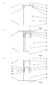
- Below, preferred exemplary embodiments of the invention are explained in more detail with reference to greatly simplified diagrammatic illustrations. The following are shown:
- Figure 1
- a cross section of a sandwich panel according to the invention in the region of an insert for forming a local reinforcement, in particular for forming a force transmission point;
- Figures 2 to 4
- single-component exemplary embodiments of the insert shown in
Figure 1 ; - Figures 5 to 10
- multi-component exemplary embodiments of the insert shown in
Figure 1 ; - Figures 11 to 13
- exemplary embodiments of the insert shown in
Figure 1 , which embodiments comprise a laterally-opened accommodation space for accommodating a foam adhesive for laterally cross-linking the insert to the core structure and/or for weight reduction; - Figure 14
- a three-dimensional view of the insert shown in
Figure 13 ; and - Figure 15
- a further exemplary embodiment according to the invention of an insert for forming a local reinforcement, in particular for forming a force transmission point.
- As shown in
Figure 1 , a sandwich panel according to the invention inter alia comprises acore structure 2 that on each side comprises at least onecover layer core structure 2 itself is formed from a multitude of cells which in the embodiment shown are of honeycomb shape, with onecell 8 being designated with a reference character representative of all the remaining cells. In this exemplary embodiment thewalls cell 8 are formed with the use of polyamide paper, as is the case with all the remaining cells of thecore structure 2, which polyamide paper is soaked, coated or impregnated with a phenolic resin. As an alternative, the polyamide paper can also comprise epoxy resin layers. The cover layers 4, 6 are, for example, semi-finished fibre products or prepregs that have been pre-impregnated with an uncured thermoplastic or duroplastic synthetic matrix. - In a single-sided recess (not designated with a reference character) of the core structure 2 a
single component insert 14 is formed for forming a local reinforcement, in particular for forming a force transmission point. Theinsert 14 is, for example, a cylindrical body made from a cured fibre composite material and is integrally formed with thesandwich panel 1, in other words during manufacture of thesandwich panel 1 it has been integrated or inserted in saidsandwich panel 1. Saidinsert 14 comprises an extension e between the cover layers 4, 6, which extension is smaller than the cover layer distance a. The cover layer distance a is, in particular, equal to the thickness of thecore structure 2. In the exemplary embodiment shown in the figure, theinsert 14 is bonded on the inside by the bottom end face 16 to thebottom cover layer 4, and thus because of its smaller extension e when compared to the cover layer distance a saidinsert 14 by itstop end face 18 on the inside is spaced apart from thetop cover layer 6. In this embodiment, bonding the bottom end face 16 to the inside of thebottom cover layer 4 takes place, for example, by way of a suitable adhesive. Of course, bonding can also take place by way of the resin of theinsert 14 and/or the resin of thebottom cover layer 4, and it is possible to do without the use of a separate adhesive. This essentially depends on the degree of curing or the degree of cross-linking of theinsert 14 and/or of thecover layer 4. - In order to compensate for a difference d between its extension e and the cover layer distance a, an
expansion compound 20 is arranged between thetop end face 18 and thetop cover layer 6. Theexpansion compound 20 has been cured or solidified and has expanded during curing. Furthermore, theexpansion compound 20 comprises adhesive characteristics so that not only is the difference d between the insert extension e and the cover layer distance a compensated for, but also theinsert 14 has been bonded to thetop cover layer 6 by means of theexpansion compound 20. For example, theexpansion compound 20 is a honeycomb adhesive which in the uncured state is viscous and thus elastic and which when subjected to pressure and temperature expands and solidifies. An epoxy adhesive with, for example, an expansion degree of 50% is a preferred expansion compound. - For the purpose of accommodating an attachment means (not shown), for example for attaching the
sandwich panel 1 to a surrounding structure, theinsert 14 and theexpansion compound 20 comprise a hole, for example a through-hole 22. Because of the arrangement of theinsert 14 on the inside, between the cover layers 4, 6, overlapping areas between theinsert 14 and the cover layers 4, 6 or between the curedcompensation compound 20 and thetop cover layer 6 are formed, which overlapping areas are radial relative to the through-hole 22. If, for example, cross tension loads are introduced into thesandwich panel 1, for example if objects are to be suspended from thesandwich panel 1, instead of the through-hole 22 it is also possible for merely a blind hole with an internal thread as a device for accommodating a fastener to have been made in theinsert 14 and in theexpansion compound 20. For the sake of clarity the through-hole 22 or a comparable accommodation device is not necessarily shown in the following figures. - According to the illustration in
Figure 2 , theinsert 14 can also compriseexpansion compound expansion compound insert 14 to at least one of the cover layers 4, 6. -
Figure 3 shows an exemplary embodiment in which fibres 28 extend from thetop end face 18 of theinsert 14, which fibres 28 are partly immersed in theexpansion compound 20 and thus result in stabilisation of thelayer 26 of connecting means. The fibres 28 are attached by their ends in theinsert 14, while their free sections are embedded in theexpansion compound 20. Of course, it is also possible for fibres to extend from the bottom end face 16 of the insert, which fibres are then partly immersed in theexpansion compound 20. - According to the illustration in
Figure 4 , theend face 18 that accommodates theexpansion compound 20 can also be structured; it can, for example, comprise a multitude of four parallelelongated indentations 30, in the manner of grooves, which then comprise theexpansion compound 20. - In
Figures 5 to 10 theinsert 14 is a multi-component design comprising a bottom 32 and a top 34. In this design theexpansion compound 20 is preferably arranged in a tolerance gap (not designated by a reference character) between the bottom 32 and the top 34. In this design the top and bottom end faces 16, 18 of theinsert 14 rest, flat on the inside, against thebottom cover layer 4 or thetop cover layer 6, with saidinsert 14 being correspondingly bonded to the aforesaid. Of course, in all the exemplary embodiments according toFigures 5 to 10 theexpansion compound 20 can additionally be arranged on the end face. - In the multi-component insert shown in
Figure 5 the bottom 32 and the top 34 are of a wedge-shaped design, wherein between their connectingsurfaces expansion compound 20 is arranged. - In the exemplary embodiment shown in
Figure 6 the bottom 32 comprises a V-shaped recess, and the top 34 comprises a corresponding V-shaped projection for entering the V-shaped accommodation device. In this embodiment the connectingsurfaces - In the exemplary embodiment shown in
Figure 7 the bottom 32 and the top 34 comprise two parallel connectingsurfaces - In the exemplary embodiment shown in
Figure 8 the top 34 comprises acircumferential sidewall 40 in the manner of a cap or a cup. In the region of itstop end face 16 the bottom 32 is encompassed by the top 34, wherein theexpansion compound 20 is arranged in the tolerance gap between the bottom 32 and the top 34. During curing 20, the expansion compound can only escape through thesidewall 40 by way of a narrowradial gap 41 between thesidewall 40 and the bottom 32 so that when thecore structure 2 and the cover layers 4, 6 are pressed to form asandwich panel 1 said expansion compound is highly compressed. - In the exemplary embodiment shown in
Figure 9 the bottom 32 and the top 34 are designed as U-profiles, wherein the top 34 comprises an interior 42 for sliding engagement with the bottom 32. The interior 42 comprises theexpansion compound 20 so that during curing of theexpansion compound 20 the bottom 32 and the top 34 are pressed apart until difference equalisation has taken place. - In the exemplary embodiment shown in
Figure 10 the bottom 32 comprises a lockinghead 44, and the top 34 is a U-shaped profile with lockingprojections 46 at the end for positive-locking interaction with the lockinghead 44. In the embodiment shown, theexpansion compound 20 is arranged between the lockinghead 44 and the lockingprojections 46 so that additionally during curing of theexpansion compound 20 the positive fit between the bottom 32 and the top 34 is strengthened. In this arrangement the positive fit preferably acts in such a manner that during the introduction of tensile loads such as cross tension loads into thesandwich panel 1 thecomponents head 44 and the locking projections compriseinclined planes surfaces -
Figures 11 to 13 show exemplary embodiments of a single-component insert 14, which exemplary embodiments in each case comprise at least oneaccommodation space 56 for accommodating a foam adhesive and for lateral cross-linking of theinsert 14 with thecore structure 2. The foam adhesive expands during curing, thus penetrating thecell 8 that accommodates theinsert 14, as a result of which in addition to the above-described connection on the cover layers an integral connection with thecore structure 2 is established. In particular, the foam adhesive can be equal to theexpansion compound - In the exemplary embodiment shown in
Figure 11 theinsert 14 is of a frame-like design comprising twoparallel webs bottom flange 62 and atop flange 64. Theaccommodation space 56 is formed between thewebs flanges core structure 2. In each case theflanges expansion compound 20. - In the exemplary embodiment shown in
Figure 12 theinsert 14 has an I-shaped cross section. Accordingly, theinsert 14 has aweb 58 that extends in the middle between abottom flange 62 and atop flange 64. In this arrangement theaccommodation space 56 can enclose theweb 58 as an annular space, or it can, for example, be divided into two partial spaces, each arranged laterally of theweb 58. In the diagram shown theflanges expansion compound accommodation space 56, in the diagram it is laterally delimited by dashed vertical lines. Accordingly, the at least oneaccommodation space 56 is formed between theflanges - In the exemplary embodiment shown in
Figure 13 theinsert 14 has a waist-like shape between itsbottom end face 16 and itstop end face 18. Theaccommodation space 56 is thus designed as an annular space with a varying cross section, with its largest cross section, as shown inFigure 14 , being arranged in the middle between the end faces 16, 18. In order to illustrate theaccommodation space 56, inFigure 14 it is shown coarsely hatched. InFigure 14 , theinsert 14 is as an example, in the region of its end faces 16, 18, connected to the cover layers 4, 6 by way of theexpansion compound - In a method according to the invention for producing such a
sandwich panel 1, prior to covering thecore structure 2 on each side with the cover layers 4, 6, the at least oneinsert 14 with the at least oneviscous expansion compound 20 is inserted into a recess in thecore structure 2, and together with thecore structure 2 and the cover layers 4, 6 is pressed to form thesandwich panel 1, wherein the at least oneexpansion compound 20 expands and solidifies. Preferably, in this arrangement theviscous expansion compound 20 is provided at such a thickness that theviscous expansion compound 20 together with the at least oneinsert 14 prior to pressing forms an extension that is greater than the command cover layer distance. Anyexcess expansion compound 20 is laterally pressed away during pressing. On end faces 16, 18 of theinsert 14, which end faces 16, 18 do not comprise expansion compound, a suitable adhesive is arranged for producing an adhesive connection between therespective end face cover layer insert 14 and/or the cover layers 4, 6 are compound structures comprising a resin matrix and if they are pressed together in the uncured state, depending on the respective degree of cross-linking, it may be possible to do without the use of an adhesive between the end faces 16, 18 of the insert, which end faces 16, 18 do not comprise expansion compound, and the cover layers 4, 6 because in this case connection of theinsert 14 to the cover layers 4, 6 can take place by way of the resin material of theinsert 14 or of thecover layer -
Figure 15 shows asandwich panel 1 with anintegrated insert 14 that without the use of theexpansion compound 20 is set to a cover layer distance a of thesandwich panel 58. To this effect, in the original state theinsert 14 has an extension u that is greater than the cover layer distance a or the thickness of acore structure 2 that accommodates theinsert 14, between abottom cover layer 4 and atop cover layer 6 of asandwich panel 1. Theinsert 14 is, for example, an uncured fibre composite component that is deformed or upset during pressing of acore structure 4 with the cover layers 4, 6, and is thus set to the cover layer distance a. To this effect theinsert 14 has a shape that supports easy deformation while nonetheless also, for example, supporting full accommodation of a through-hole 22. In the exemplary embodiment shown in the diagram theinsert 14 is I-shaped with aweb 58 that extends in the middle between abottom flange 62 and atop flange 64. Theweb 58 is deformed during pressing, and thus the original extension u of theinsert 14 is reduced. - In a method according to the invention for producing such a
sandwich panel 1, prior to covering thecore structure 2 on each side with the cover layers 4, 6, the at least oneinsert 14, in its original elastic state in which it is larger than the cover layer distance a, is inserted into a cutout in thecore structure 2, and together with the cover layers 4, 6 is pressed to form thesandwich panel 1, wherein saidinsert 14 cures after its deformation. - It is expressly pointed out that even if the above-mentioned exemplary embodiments are considered individually all the characteristics of the exemplary embodiments can be combined individually.
- Disclosed are a sandwich panel with at least one insert for forming a local reinforcement, which insert is smaller than a cover layer distance of the sandwich panel, wherein a difference between its extension and the cover layer distance from a previously viscous expansion compound with adhesive properties, which expansion compound has solidified during the pressing of the sandwich panel, is compensated for; a sandwich panel with at least one previously elastic insert whose original extension as a result of deformation during pressing of the sandwich panel is reduced; as well as a method for producing such sandwich panels.
-
- 1
- Sandwich panel
- 2
- Core structure
- 4
- Bottom cover layer
- 6
- Top cover layer
- 8
- Cell (honeycomb design)
- 10
- Wall (cell)
- 12
- Wall (cell)
- 14
- Insert
- 16
- Bottom end face
- 18
- Top end face
- 20
- Expansion compound
- 22
- Through-hole
- 26
- Expansion compound
- 28
- Fibre
- 30
- Elongated indentation
- 32
- Bottom / insert component
- 34
- Top / insert component
- 36
- Connecting surface
- 38
- Connecting surface
- 40
- Sidewall
- 41
- Radial gap
- 42
- Interior
- 44
- Locking head
- 46
- Locking projections
- 48
- Inclined plane
- 50
- Inclined plane
- 52
- Locking surface
- 54
- Locking surface
- 56
- Accommodation space
- 58
- Web / body portion
- 60
- Web / body portion
- 62
- Bottom flange / body portion
- 64
- Top flange / body portion
- e
- Extension
- a
- Cover layer distance
- d
- Difference
- u
- Extension in the original state
Claims (13)
- A sandwich panel (1) with a core structure (2) and cover layers (4, 6) arranged on each side, wherein the core structure (2) comprises a multitude of, in particular honeycomb-shaped, cells (8), and with at least one insert (14) for forming a local reinforcement, in particular for forming a force transmission point, characterised in that the at least one insert (14) is arranged between the cover layers (4, 6), wherein said insert (14) is smaller than the cover layer distance (a), and a difference (d) between its extension (e) and the cover layer distance (a) of at least one cured expansion compound (20, 26) is compensated for with adhesive characteristics.
- The sandwich panel according to claim 1, wherein the expansion compound (20, 26) is arranged at least between the insert (14) and a cover layer (4, 6).
- The sandwich panel according to claim 1, wherein the at least one insert (14) comprises a multi-component design, and the expansion compound (26) is arranged at least between the insert components (32, 34).
- The sandwich panel according to claim 3, wherein the insert components (32, 34) of the at least one insert (14) cooperate with positive-locking fit.
- The sandwich panel according to any one of the preceding claims, wherein fibres (28) are arranged in the expansion compound (20).
- The sandwich panel according to any one of the preceding claims, wherein the at least one insert (14) is structured in the region of the expansion compound (20).
- The sandwich panel according to any one of the preceding claims, wherein the at least one insert (14) is at least in some sections circumferentially bonded to the core structure (2).
- The sandwich panel according to claim 7, wherein the at least one insert (14) has a body portion (58) comprising a reduction in its cross section when compared to body portions (62, 64) on the side of the cover layers.
- A method for forming a sandwich panel (1) according to any one of the preceding claims, wherein prior to covering a core structure (2) on both sides with cover layers (4, 6), at least one insert (14) that has a lesser expansion (e) than a command cover layer distance (a) is inserted, together with at least one viscous expansion compound (20, 26) with adhesive characteristics, into a section of the core structure, and together with the core structure (2) and the cover layers (4, 6) is pressed to form the sandwich panel (1), wherein the expansion compound (20, 26) expands and cures.
- The method for forming a sandwich panel (1) according to claim 9, wherein the at least one viscous expansion compound (20, 26) is provided at a thickness sufficient for the viscous expansion compound (20, 26) together with the at least one insert (14) prior to pressing to form an extension that is greater than the command cover layer distance (a).
- A sandwich panel according to claim 9, wherein the at least one insert (14) is arranged in a not-completely-cured state in the core structure (2) and subsequently cures during pressing.
- A sandwich panel (1) with a core structure (2) and cover layers (4, 6) arranged on each side, wherein the core structure (2) comprises a multitude of, in particular honeycomb-shaped, cells (8), and with at least one insert (14) for forming a local reinforcement, in particular for forming a force transmission point, characterised in that the at least one insert (14) is arranged between the cover layers (4, 6), wherein it is cured and deformed when compared to an elastic original state.
- A method for forming a sandwich panel (1) according to claim 12, wherein prior to covering a core structure (2) on both sides with cover layers (4, 6), at least one insert (14), in its original elastic state in which it is larger than the command cover layer distance (a), is inserted into a cutout in the core structure (2), and together with the core structure (2) and the cover layers (4, 6) is pressed to form the sandwich panel (58), wherein, during pressing, said insert (14) cures in its deformed state.
Applications Claiming Priority (1)
| Application Number | Priority Date | Filing Date | Title |
|---|---|---|---|
| DE102013224203.4A DE102013224203A1 (en) | 2013-11-27 | 2013-11-27 | Sandwich panels and method of making sandwich panels |
Publications (2)
| Publication Number | Publication Date |
|---|---|
| EP2878420A1 true EP2878420A1 (en) | 2015-06-03 |
| EP2878420B1 EP2878420B1 (en) | 2020-11-18 |
Family
ID=52102414
Family Applications (1)
| Application Number | Title | Priority Date | Filing Date |
|---|---|---|---|
| EP14195260.6A Active EP2878420B1 (en) | 2013-11-27 | 2014-11-27 | Sandwich panels and method for producing sandwich panels |
Country Status (3)
| Country | Link |
|---|---|
| US (1) | US9682529B2 (en) |
| EP (1) | EP2878420B1 (en) |
| DE (1) | DE102013224203A1 (en) |
Families Citing this family (4)
| Publication number | Priority date | Publication date | Assignee | Title |
|---|---|---|---|---|
| US20170259521A1 (en) * | 2016-02-08 | 2017-09-14 | Bell Helicopter Textron Inc. | Large Cell Core Stiffened Panels with Solid Inserts |
| US11732740B2 (en) | 2020-05-12 | 2023-08-22 | Sky Climber Fasteners LLC | Blind fastener |
| EP4182576A4 (en) | 2020-07-20 | 2024-08-07 | Sky Climber Fasteners LLC | RIVETLESS NUT PLATE |
| WO2023014964A1 (en) | 2021-08-06 | 2023-02-09 | Sky Climber Fasteners LLC | Panel fastener |
Citations (10)
| Publication number | Priority date | Publication date | Assignee | Title |
|---|---|---|---|---|
| US2607447A (en) | 1946-02-26 | 1952-08-19 | Us Plywood Corp | Fastener |
| GB921569A (en) | 1962-01-15 | 1963-03-20 | Frederick William Rohe | Anchor nut for use with sandwich-type panels |
| US3716092A (en) | 1970-04-14 | 1973-02-13 | Illinois Tool Works | Panel insert and method of installation |
| US4399642A (en) | 1980-07-24 | 1983-08-23 | The Boeing Company | Aircraft floor panel installation system |
| US4981735A (en) | 1989-09-05 | 1991-01-01 | The United States Of America As Represented By The Secretary Of The Army | Two piece threaded mounting insert with adhesive for use with honeycomb composite |
| EP0443364A2 (en) * | 1990-02-15 | 1991-08-28 | BASF Aktiengesellschaft | Laminates with stable fastening points |
| US5093957A (en) | 1991-07-08 | 1992-03-10 | Atr International, Inc. | Compression fitting for use in a two-sided honeycomb panel |
| EP1024301A2 (en) | 1999-01-26 | 2000-08-02 | Sakura Rubber Co., Ltd. | Honeycomb panel fixing device |
| WO2001081468A1 (en) * | 2000-04-20 | 2001-11-01 | Vantico Ag | Coherent insert |
| DE102009010961A1 (en) | 2009-02-28 | 2010-09-02 | Fischerwerke Gmbh & Co. Kg | Method for attaching inserts in lightweight panels, appropriately equipped insert body and their corresponding use |
Family Cites Families (3)
| Publication number | Priority date | Publication date | Assignee | Title |
|---|---|---|---|---|
| DE19731604C2 (en) * | 1997-07-18 | 2002-04-11 | Dwa Deutsche Waggonbau Gmbh | Sandwich panel with integrated profile, especially for vehicle construction |
| EP1843894B1 (en) * | 2005-01-31 | 2014-12-17 | Kompozitor Muanyagipari Fejleszto Kft. | Structural element, especially laminated panel and process for the manufacturing of such structural element |
| EP2251250A1 (en) | 2009-05-05 | 2010-11-17 | Sika Technology AG | Bonding with adhesive beads or plots |
-
2013
- 2013-11-27 DE DE102013224203.4A patent/DE102013224203A1/en not_active Withdrawn
-
2014
- 2014-11-27 EP EP14195260.6A patent/EP2878420B1/en active Active
- 2014-11-27 US US14/555,617 patent/US9682529B2/en active Active
Patent Citations (10)
| Publication number | Priority date | Publication date | Assignee | Title |
|---|---|---|---|---|
| US2607447A (en) | 1946-02-26 | 1952-08-19 | Us Plywood Corp | Fastener |
| GB921569A (en) | 1962-01-15 | 1963-03-20 | Frederick William Rohe | Anchor nut for use with sandwich-type panels |
| US3716092A (en) | 1970-04-14 | 1973-02-13 | Illinois Tool Works | Panel insert and method of installation |
| US4399642A (en) | 1980-07-24 | 1983-08-23 | The Boeing Company | Aircraft floor panel installation system |
| US4981735A (en) | 1989-09-05 | 1991-01-01 | The United States Of America As Represented By The Secretary Of The Army | Two piece threaded mounting insert with adhesive for use with honeycomb composite |
| EP0443364A2 (en) * | 1990-02-15 | 1991-08-28 | BASF Aktiengesellschaft | Laminates with stable fastening points |
| US5093957A (en) | 1991-07-08 | 1992-03-10 | Atr International, Inc. | Compression fitting for use in a two-sided honeycomb panel |
| EP1024301A2 (en) | 1999-01-26 | 2000-08-02 | Sakura Rubber Co., Ltd. | Honeycomb panel fixing device |
| WO2001081468A1 (en) * | 2000-04-20 | 2001-11-01 | Vantico Ag | Coherent insert |
| DE102009010961A1 (en) | 2009-02-28 | 2010-09-02 | Fischerwerke Gmbh & Co. Kg | Method for attaching inserts in lightweight panels, appropriately equipped insert body and their corresponding use |
Also Published As
| Publication number | Publication date |
|---|---|
| US9682529B2 (en) | 2017-06-20 |
| DE102013224203A1 (en) | 2015-05-28 |
| EP2878420B1 (en) | 2020-11-18 |
| US20150147516A1 (en) | 2015-05-28 |
Similar Documents
| Publication | Publication Date | Title |
|---|---|---|
| EP2878420B1 (en) | Sandwich panels and method for producing sandwich panels | |
| EP2173539B1 (en) | Apparatus and method for forming fibre reinforced composite structures | |
| CN102143839B (en) | Sandwich panel with integrated reinforcement structure and method of manufacturing the same | |
| CN101511673A (en) | Panel assembly and method of erecting a panel assembly | |
| US8622346B2 (en) | Fuselage structure made of composite material | |
| EP2942269B1 (en) | Method for manufacturing a load bearing structure and such a load bearing structure | |
| US8277938B2 (en) | Part of composite material having a wedge between two zones | |
| RU2242369C1 (en) | Bearing assembly of a three-layer panel | |
| US7722944B2 (en) | Piece made of composite material with areas of different thickness | |
| US8973870B2 (en) | Wall component for an aircraft | |
| JP7830229B2 (en) | Screwed inserts for bonding outer panels, sandwich panels including the same, and related methods | |
| US20170028653A1 (en) | Apparatus and method for forming fiber reinforced composite structures | |
| US9527573B2 (en) | Pressurized aircraft fuselage comprising a pressure bulkhead movably fixed to the fuselage | |
| EP2610046B1 (en) | Method for joining components through mechanical adhesion and mechanical adhesion joint for joining components | |
| EP3042846B1 (en) | Floor arrangement with curved floor panels for an aircraft | |
| EP2818403B1 (en) | Locally reinforced aircraft structural component | |
| US20140224410A1 (en) | Apparatus and method for forming fiber reinforced composite structures | |
| EP3119577A1 (en) | Primary structure connecting element for aircraft and method for manufacturing the connecting element | |
| RU200232U1 (en) | MULTI-LAYER PANEL SUPPORT ASSEMBLY | |
| EP2781345B1 (en) | Method and system for producing composite structures | |
| EP4302975A1 (en) | Filling element for the manufacture of aircraft parts and aircraft part comprising such a filling element | |
| US20180291940A1 (en) | Fastenerless anti-peel adhesive joint | |
| EP4488529A1 (en) | Insert installation into a sandwich structure, sandwich structure and hollow body | |
| RU2674205C1 (en) | Structure of size-stable platform of laminated polymer composite material | |
| CN111098518A (en) | Method of manufacturing a panel of a wind turbine nacelle |
Legal Events
| Date | Code | Title | Description |
|---|---|---|---|
| PUAI | Public reference made under article 153(3) epc to a published international application that has entered the european phase |
Free format text: ORIGINAL CODE: 0009012 |
|
| 17P | Request for examination filed |
Effective date: 20141127 |
|
| AK | Designated contracting states |
Kind code of ref document: A1 Designated state(s): AL AT BE BG CH CY CZ DE DK EE ES FI FR GB GR HR HU IE IS IT LI LT LU LV MC MK MT NL NO PL PT RO RS SE SI SK SM TR |
|
| AX | Request for extension of the european patent |
Extension state: BA ME |
|
| R17P | Request for examination filed (corrected) |
Effective date: 20150724 |
|
| RBV | Designated contracting states (corrected) |
Designated state(s): AL AT BE BG CH CY CZ DE DK EE ES FI FR GB GR HR HU IE IS IT LI LT LU LV MC MK MT NL NO PL PT RO RS SE SI SK SM TR |
|
| STAA | Information on the status of an ep patent application or granted ep patent |
Free format text: STATUS: EXAMINATION IS IN PROGRESS |
|
| 17Q | First examination report despatched |
Effective date: 20171026 |
|
| GRAP | Despatch of communication of intention to grant a patent |
Free format text: ORIGINAL CODE: EPIDOSNIGR1 |
|
| STAA | Information on the status of an ep patent application or granted ep patent |
Free format text: STATUS: GRANT OF PATENT IS INTENDED |
|
| INTG | Intention to grant announced |
Effective date: 20200609 |
|
| GRAS | Grant fee paid |
Free format text: ORIGINAL CODE: EPIDOSNIGR3 |
|
| GRAA | (expected) grant |
Free format text: ORIGINAL CODE: 0009210 |
|
| STAA | Information on the status of an ep patent application or granted ep patent |
Free format text: STATUS: THE PATENT HAS BEEN GRANTED |
|
| AK | Designated contracting states |
Kind code of ref document: B1 Designated state(s): AL AT BE BG CH CY CZ DE DK EE ES FI FR GB GR HR HU IE IS IT LI LT LU LV MC MK MT NL NO PL PT RO RS SE SI SK SM TR |
|
| REG | Reference to a national code |
Ref country code: GB Ref legal event code: FG4D |
|
| REG | Reference to a national code |
Ref country code: CH Ref legal event code: EP |
|
| REG | Reference to a national code |
Ref country code: IE Ref legal event code: FG4D |
|
| REG | Reference to a national code |
Ref country code: DE Ref legal event code: R096 Ref document number: 602014072424 Country of ref document: DE |
|
| REG | Reference to a national code |
Ref country code: AT Ref legal event code: REF Ref document number: 1335257 Country of ref document: AT Kind code of ref document: T Effective date: 20201215 |
|
| REG | Reference to a national code |
Ref country code: AT Ref legal event code: MK05 Ref document number: 1335257 Country of ref document: AT Kind code of ref document: T Effective date: 20201118 |
|
| REG | Reference to a national code |
Ref country code: NL Ref legal event code: MP Effective date: 20201118 |
|
| PG25 | Lapsed in a contracting state [announced via postgrant information from national office to epo] |
Ref country code: NO Free format text: LAPSE BECAUSE OF FAILURE TO SUBMIT A TRANSLATION OF THE DESCRIPTION OR TO PAY THE FEE WITHIN THE PRESCRIBED TIME-LIMIT Effective date: 20210218 Ref country code: PT Free format text: LAPSE BECAUSE OF FAILURE TO SUBMIT A TRANSLATION OF THE DESCRIPTION OR TO PAY THE FEE WITHIN THE PRESCRIBED TIME-LIMIT Effective date: 20210318 Ref country code: FI Free format text: LAPSE BECAUSE OF FAILURE TO SUBMIT A TRANSLATION OF THE DESCRIPTION OR TO PAY THE FEE WITHIN THE PRESCRIBED TIME-LIMIT Effective date: 20201118 Ref country code: RS Free format text: LAPSE BECAUSE OF FAILURE TO SUBMIT A TRANSLATION OF THE DESCRIPTION OR TO PAY THE FEE WITHIN THE PRESCRIBED TIME-LIMIT Effective date: 20201118 Ref country code: GR Free format text: LAPSE BECAUSE OF FAILURE TO SUBMIT A TRANSLATION OF THE DESCRIPTION OR TO PAY THE FEE WITHIN THE PRESCRIBED TIME-LIMIT Effective date: 20210219 |
|
| PG25 | Lapsed in a contracting state [announced via postgrant information from national office to epo] |
Ref country code: BG Free format text: LAPSE BECAUSE OF FAILURE TO SUBMIT A TRANSLATION OF THE DESCRIPTION OR TO PAY THE FEE WITHIN THE PRESCRIBED TIME-LIMIT Effective date: 20210218 Ref country code: AT Free format text: LAPSE BECAUSE OF FAILURE TO SUBMIT A TRANSLATION OF THE DESCRIPTION OR TO PAY THE FEE WITHIN THE PRESCRIBED TIME-LIMIT Effective date: 20201118 Ref country code: IS Free format text: LAPSE BECAUSE OF FAILURE TO SUBMIT A TRANSLATION OF THE DESCRIPTION OR TO PAY THE FEE WITHIN THE PRESCRIBED TIME-LIMIT Effective date: 20210318 Ref country code: PL Free format text: LAPSE BECAUSE OF FAILURE TO SUBMIT A TRANSLATION OF THE DESCRIPTION OR TO PAY THE FEE WITHIN THE PRESCRIBED TIME-LIMIT Effective date: 20201118 Ref country code: LV Free format text: LAPSE BECAUSE OF FAILURE TO SUBMIT A TRANSLATION OF THE DESCRIPTION OR TO PAY THE FEE WITHIN THE PRESCRIBED TIME-LIMIT Effective date: 20201118 Ref country code: SE Free format text: LAPSE BECAUSE OF FAILURE TO SUBMIT A TRANSLATION OF THE DESCRIPTION OR TO PAY THE FEE WITHIN THE PRESCRIBED TIME-LIMIT Effective date: 20201118 |
|
| REG | Reference to a national code |
Ref country code: LT Ref legal event code: MG9D |
|
| PG25 | Lapsed in a contracting state [announced via postgrant information from national office to epo] |
Ref country code: HR Free format text: LAPSE BECAUSE OF FAILURE TO SUBMIT A TRANSLATION OF THE DESCRIPTION OR TO PAY THE FEE WITHIN THE PRESCRIBED TIME-LIMIT Effective date: 20201118 |
|
| REG | Reference to a national code |
Ref country code: CH Ref legal event code: PL |
|
| PG25 | Lapsed in a contracting state [announced via postgrant information from national office to epo] |
Ref country code: EE Free format text: LAPSE BECAUSE OF FAILURE TO SUBMIT A TRANSLATION OF THE DESCRIPTION OR TO PAY THE FEE WITHIN THE PRESCRIBED TIME-LIMIT Effective date: 20201118 Ref country code: CZ Free format text: LAPSE BECAUSE OF FAILURE TO SUBMIT A TRANSLATION OF THE DESCRIPTION OR TO PAY THE FEE WITHIN THE PRESCRIBED TIME-LIMIT Effective date: 20201118 Ref country code: SM Free format text: LAPSE BECAUSE OF FAILURE TO SUBMIT A TRANSLATION OF THE DESCRIPTION OR TO PAY THE FEE WITHIN THE PRESCRIBED TIME-LIMIT Effective date: 20201118 Ref country code: SK Free format text: LAPSE BECAUSE OF FAILURE TO SUBMIT A TRANSLATION OF THE DESCRIPTION OR TO PAY THE FEE WITHIN THE PRESCRIBED TIME-LIMIT Effective date: 20201118 Ref country code: RO Free format text: LAPSE BECAUSE OF FAILURE TO SUBMIT A TRANSLATION OF THE DESCRIPTION OR TO PAY THE FEE WITHIN THE PRESCRIBED TIME-LIMIT Effective date: 20201118 Ref country code: LT Free format text: LAPSE BECAUSE OF FAILURE TO SUBMIT A TRANSLATION OF THE DESCRIPTION OR TO PAY THE FEE WITHIN THE PRESCRIBED TIME-LIMIT Effective date: 20201118 Ref country code: LU Free format text: LAPSE BECAUSE OF NON-PAYMENT OF DUE FEES Effective date: 20201127 |
|
| REG | Reference to a national code |
Ref country code: BE Ref legal event code: MM Effective date: 20201130 |
|
| REG | Reference to a national code |
Ref country code: DE Ref legal event code: R097 Ref document number: 602014072424 Country of ref document: DE |
|
| PG25 | Lapsed in a contracting state [announced via postgrant information from national office to epo] |
Ref country code: LI Free format text: LAPSE BECAUSE OF NON-PAYMENT OF DUE FEES Effective date: 20201130 Ref country code: MC Free format text: LAPSE BECAUSE OF FAILURE TO SUBMIT A TRANSLATION OF THE DESCRIPTION OR TO PAY THE FEE WITHIN THE PRESCRIBED TIME-LIMIT Effective date: 20201118 Ref country code: CH Free format text: LAPSE BECAUSE OF NON-PAYMENT OF DUE FEES Effective date: 20201130 Ref country code: DK Free format text: LAPSE BECAUSE OF FAILURE TO SUBMIT A TRANSLATION OF THE DESCRIPTION OR TO PAY THE FEE WITHIN THE PRESCRIBED TIME-LIMIT Effective date: 20201118 |
|
| PLBE | No opposition filed within time limit |
Free format text: ORIGINAL CODE: 0009261 |
|
| STAA | Information on the status of an ep patent application or granted ep patent |
Free format text: STATUS: NO OPPOSITION FILED WITHIN TIME LIMIT |
|
| 26N | No opposition filed |
Effective date: 20210819 |
|
| PG25 | Lapsed in a contracting state [announced via postgrant information from national office to epo] |
Ref country code: NL Free format text: LAPSE BECAUSE OF FAILURE TO SUBMIT A TRANSLATION OF THE DESCRIPTION OR TO PAY THE FEE WITHIN THE PRESCRIBED TIME-LIMIT Effective date: 20201118 Ref country code: AL Free format text: LAPSE BECAUSE OF FAILURE TO SUBMIT A TRANSLATION OF THE DESCRIPTION OR TO PAY THE FEE WITHIN THE PRESCRIBED TIME-LIMIT Effective date: 20201118 Ref country code: IE Free format text: LAPSE BECAUSE OF NON-PAYMENT OF DUE FEES Effective date: 20201127 Ref country code: IT Free format text: LAPSE BECAUSE OF FAILURE TO SUBMIT A TRANSLATION OF THE DESCRIPTION OR TO PAY THE FEE WITHIN THE PRESCRIBED TIME-LIMIT Effective date: 20201118 |
|
| PG25 | Lapsed in a contracting state [announced via postgrant information from national office to epo] |
Ref country code: ES Free format text: LAPSE BECAUSE OF FAILURE TO SUBMIT A TRANSLATION OF THE DESCRIPTION OR TO PAY THE FEE WITHIN THE PRESCRIBED TIME-LIMIT Effective date: 20201118 Ref country code: SI Free format text: LAPSE BECAUSE OF FAILURE TO SUBMIT A TRANSLATION OF THE DESCRIPTION OR TO PAY THE FEE WITHIN THE PRESCRIBED TIME-LIMIT Effective date: 20201118 |
|
| PGFP | Annual fee paid to national office [announced via postgrant information from national office to epo] |
Ref country code: GB Payment date: 20211119 Year of fee payment: 8 |
|
| PG25 | Lapsed in a contracting state [announced via postgrant information from national office to epo] |
Ref country code: IS Free format text: LAPSE BECAUSE OF FAILURE TO SUBMIT A TRANSLATION OF THE DESCRIPTION OR TO PAY THE FEE WITHIN THE PRESCRIBED TIME-LIMIT Effective date: 20210318 Ref country code: TR Free format text: LAPSE BECAUSE OF FAILURE TO SUBMIT A TRANSLATION OF THE DESCRIPTION OR TO PAY THE FEE WITHIN THE PRESCRIBED TIME-LIMIT Effective date: 20201118 Ref country code: MT Free format text: LAPSE BECAUSE OF FAILURE TO SUBMIT A TRANSLATION OF THE DESCRIPTION OR TO PAY THE FEE WITHIN THE PRESCRIBED TIME-LIMIT Effective date: 20201118 Ref country code: CY Free format text: LAPSE BECAUSE OF FAILURE TO SUBMIT A TRANSLATION OF THE DESCRIPTION OR TO PAY THE FEE WITHIN THE PRESCRIBED TIME-LIMIT Effective date: 20201118 |
|
| PG25 | Lapsed in a contracting state [announced via postgrant information from national office to epo] |
Ref country code: MK Free format text: LAPSE BECAUSE OF FAILURE TO SUBMIT A TRANSLATION OF THE DESCRIPTION OR TO PAY THE FEE WITHIN THE PRESCRIBED TIME-LIMIT Effective date: 20201118 |
|
| PG25 | Lapsed in a contracting state [announced via postgrant information from national office to epo] |
Ref country code: BE Free format text: LAPSE BECAUSE OF NON-PAYMENT OF DUE FEES Effective date: 20201130 |
|
| GBPC | Gb: european patent ceased through non-payment of renewal fee |
Effective date: 20221127 |
|
| PG25 | Lapsed in a contracting state [announced via postgrant information from national office to epo] |
Ref country code: GB Free format text: LAPSE BECAUSE OF NON-PAYMENT OF DUE FEES Effective date: 20221127 |
|
| PGFP | Annual fee paid to national office [announced via postgrant information from national office to epo] |
Ref country code: DE Payment date: 20231121 Year of fee payment: 10 |
|
| REG | Reference to a national code |
Ref country code: DE Ref legal event code: R119 Ref document number: 602014072424 Country of ref document: DE |
|
| PG25 | Lapsed in a contracting state [announced via postgrant information from national office to epo] |
Ref country code: DE Free format text: LAPSE BECAUSE OF NON-PAYMENT OF DUE FEES Effective date: 20250603 |
|
| PGFP | Annual fee paid to national office [announced via postgrant information from national office to epo] |
Ref country code: FR Payment date: 20251125 Year of fee payment: 12 |