Technical field
-
The present invention relates to an End of Line (EOL) module for an alarm system, in particular to an EOL module which employs a resistor.
Background art
-
An alarm system is a product which is inextricably linked with production and life in society. It generally uses sound or light, etc. to remind or warn people to carry out some action, and is often applied in such fields as system failure, safety precautions, transport and communication, medical assistance, emergency rescue, sensing and detection. Examples are fire alarm systems and firedamp alarm systems, which are commonly seen in everyday life.
-
An alarm system generally comprises a field side and a control side. Sensors in the field side are used for sensing whether a danger signal is present; for example, they may sense smoke or firedamp, etc. Having sensed the presence of a danger signal, a sensor will immediately send a signal to the control side. After receiving the signal, the control side supplies electrical energy to a warning device on the field side, so that said device issues an alarm in the form of sound or light, etc. The field side and control side are generally separated by a certain distance. For example, in the case of a fire alarm system, the control side is generally located in a central control room of the building, while the field side is located in various rooms inside the building. The control side and field side are generally connected by a transmission line such as a cable, for the transmission of signals and electrical energy between the two. This transmission line is also called a "field wire".
-
The field wire is responsible for fulfilling the function of transmitting signals and electrical energy, so in the pre-alarm stage, the control side will continuously monitor the field wire to determine whether it has an open circuit or short circuit, in order to ensure that the alarm system can operate normally in an alarm stage. However, besides open circuit and short circuit faults, the field wire might also be in a "creeping open circuit (creeping open)" or "creeping short circuit (creeping short)" state.
-
A creeping open circuit refers to a state in which the field wire has increased resistance, but has not yet developed a full open circuit. A creeping short circuit refers to a state in which the electrical isolation between two or more field wires has deteriorated, but a full short circuit has not yet occurred. Moreover, full open circuits and full short circuits may be regarded as extreme special cases of creeping open circuits and creeping short circuits. There are many environmental and human factors which lead to creeping open circuits and creeping short circuits. For example, in a highly humid environment, rust readily occurs on contacts at the connection nodes between a field wire and an alarm system, causing the node resistance to increase, leading to a creeping open circuit state. Another example is that the structure of the field wires is easily destroyed by drilling work etc. in a building, with the cable being left in a loosely overlapping state, leading to a creeping open circuit or creeping short circuit state.
-
Such a "creeping open" or "creeping short" state has a major impact on the operation of field wires. The impact is especially great when the field wire supplies electrical energy to a warning device, and may lead to failure of the alarm system. A warning device such as a loudspeaker needs a certain amount of electrical energy in order to start up; if there is a creeping open circuit in an alarm system line, then a larger voltage will be expended at the position of the creeping open circuit, so that the loudspeaker cannot obtain sufficient voltage, and cannot start up normally when an alarm needs to be raised. If there is a creeping short circuit in the alarm system, the loudspeaker will be unable to obtain sufficient current, and this will similarly lead to an alarm fault. Thus, it is necessary to detect the occurrence of a fault before a full short circuit or full open circuit occurs, i.e. during the creeping open circuit or creeping short circuit stage, in order to avoid the phenomenon of alarm failure.
-
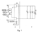
At present, an End of Line (EOL) module is generally used in an alarm system to detect the occurrence of creeping open circuit and creeping short circuit faults. Fig. 1 shows the basic structure of a fire alarm system with an EOL module, wherein the EOL module consists of a resistor, and is connected into the alarm system circuit by pins T1 and T2. The fire alarm system comprises a control side C and field side F. As Fig. 1 shows, the EOL module is connected in parallel with loudspeakers h, i and j, and connected in series with resistors R2 and R3, and then after the series connection is supplied with a voltage V2. At this time, the direction of current flow in the EOL module is from T2 to T1; the loudspeakers h, i and j have opposite polarity to the voltage V2 and are therefore in a non-operational state, so consume no current. A control port MON_CTRL of a switch SW1 is used to control the voltage applied across the EOL module by controlling the switch SW1. When SW1 is conducting, the voltage across the EOL module is V2; when SW1 is open, the voltage across the EOL module is V2 - VREF1.
-
The alarm system circuit in Fig. 1 is in a monitoring mode, when the control side C monitors whether a creeping open circuit or creeping short circuit fault has occurred by monitoring the size of the resistance of the field side F. In the event of a creeping short circuit, the resistance of the field side will decrease; in the event of a creeping open circuit, the resistance of the field side will increase. Specifically, as Fig. 1 shows, the control side measures the resistance RF of the field side by measuring voltages VREF1 and VREF2 at two ends of the extracting resistor R2, the conversion relation being RF=[(V2-VREF1)/(VREF1-VREF2)]*R2.
-
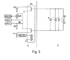
When a sensor (not shown in Fig. 1) has sensed a fire emergency, it will send a signal to a control port DIR_CTRL of a double-pole double-throw switch N1 on the control side C, thereby inducing the double-pole double-throw switch N1 to switch over. The circuit in Fig. 1 will then change to the structure shown in Fig. 2, so that the fire alarm system is in an alarm mode. The EOL module and loudspeakers h, i and j are supplied with a voltage by V1, the direction of current flow in EOL is from T1 to T2, and the loudspeakers issue a sound alarm.
-
Since the loudspeakers are connected in parallel with the EOL module during an alarm, it is necessary that the resistance of the resistor in the EOL module is very large (generally, it must be no less than 1 kΩ), to prevent current from bypassing the loudspeakers, and thereby prevent a situation in which the loudspeakers are unable to start up due to insufficient current. However, resistors with high resistances have a higher resistance tolerance. For example, the resistance tolerance of a 1 kΩ resistor is generally in the range of ±1%, i.e. ±10 Ω. Thus, if the change in resistance caused by a creeping open circuit or creeping short circuit is relatively small, it is easily "drowned" in the resistance tolerance range of the resistor in the EOL module, so that it is not possible to detect creeping open circuit and creeping short circuit faults. Thus, if a resistor with an excessively high resistance is used as the EOL module, it is difficult to detect the occurrence of creeping open circuit and creeping short circuit faults precisely, and it is often the case that creeping open circuit and creeping short circuit faults can only be detected after worsening to a certain degree. Furthermore, owing to its high resistance tolerance, if a resistor with high resistance is used as an EOL module, calibration must be performed before installation. Even after calibration, resistance drift due to drift in temperature, etc. is also large, so the demands of precise detection can still not be met.
Content of the invention
-
The present invention is intended to provide an EOL module for an alarm system, which is capable of precisely detecting a creeping open circuit or creeping short circuit fault when such a fault has just begun to occur.
-
The present invention provides an EOL module for an alarm system, comprising: a first terminal and a second terminal; a switch unit and a resistor connected in series between the first and second terminals; a voltage polarity sensing circuit coupled between the first and second terminals, for sensing the polarity of a voltage between the first and second terminals, and when the sensed polarity indicates that the alarm system is in a monitoring mode, controlling the switch unit to conduct, and when the sensed polarity indicates that the alarm system is in an alarm mode, controlling the switch unit to turn off.
-
The resistance of the resistor in such an EOL module can be set at a smaller value. Thus the tiny fluctuation in resistance caused by creeping open circuits and creeping short circuits in the initial period of their occurrence can be detected, and will not be drowned in the resistance fluctuation range of the resistor. Thus more precise checking of field wires is possible, and a creeping open circuit or creeping short circuit fault can be precisely detected when such a fault has just begun to occur.
-
In the EOL module provided according to the present invention, the voltage polarity sensing circuit comprises a first switching device and a control unit, while the switch unit comprises a second switching device, wherein the first and second switching devices are switched in a linked manner under the control of the control unit.
-
The EOL module provided according to the present invention, wherein the control unit in the voltage polarity sensing circuit determines the voltage polarity sensed thereby according to the direction of current flow through the control unit.
-
The EOL module provided according to the present invention, wherein the voltage polarity sensing circuit further comprises a first one-way conducting element and a second one-way conducting element, wherein the first switching device can connect one of the first and second one-way conducting elements in series with the control unit between the first and second terminals, and the respective directions of the first and second one-way conducting elements are opposite. The EOL module provided according to the present invention, wherein either one of the first one-way conducting element and second one-way conducting element is a diode.
-
The EOL module provided according to the present invention, wherein there is a first charge storage device connected in parallel with the first switching device between the first one-way conducting element and the control unit, and a second charge storage device connected in parallel with the first switching device between the second one-way conducting element and the control unit. The EOL module provided according to the present invention, wherein either one of the first charge storage device and second charge storage device is a capacitor.
-
The EOL module provided according to the present invention, wherein the first and second switching devices and the control unit are embodied as a latching relay. The EOL module provided according to the present invention, wherein the latching relay is an electromagnetic latching relay, and the control unit is an excitation coil.
-
The EOL module provided according to the present invention, wherein the latching relay is a double-pole double-throw relay. The EOL module provided according to the present invention, wherein a threshold voltage for operation of the excitation coil of the latching relay is lower than an operating voltage between the first terminal and second terminal when the alarm system is in the alarm mode. The EOL module provided according to the present invention, wherein a monitoring voltage of the alarm system in the monitoring mode is lower than the threshold voltage for operation of the excitation coil of the latching relay.
-
The present invention further provides a control method for an alarm system, wherein one or more warning devices is/are connected in parallel on two lines led out from a control side of the alarm system, and an EOL module is connected at a far end of the two lines, the control method comprising: when the alarm system is in an alarm mode, applying a first voltage to the line, to drive an action of the warning device, while at the same time breaking the connection between the EOL module and the line; when the alarm system is in a monitoring mode, applying a second voltage to the line, so that the EOL module is coupled into a monitoring circuit comprising the line; when the alarm system is in the monitoring mode and the EOL module has been coupled into the monitoring circuit, applying a third voltage to the line, to detect whether a fault has occurred on the line; wherein the first voltage is of opposite polarity to the second and third voltages, and the third voltage is lower than the second voltage.
-
The control method provided according to the present invention, further comprising a step of initializing the EOL module, the initialization step comprising: applying the first voltage to the line, so that the EOL module is initialized by being disconnected from the line; and applying to the EOL module the third voltage which is lower than the first voltage, to monitor whether a first fault has occurred in the line connected to the alarm system. Here, the first fault includes creeping short circuits and connection errors.
-
The control method provided according to the present invention, the initialization step further comprising: applying the second voltage to the line, so that the EOL module is coupled into the monitoring circuit comprising the line; applying to the line the third voltage which is lower than the second voltage, to detect whether a second fault has occurred in the line of the alarm system. Here, preferably, the second fault includes creeping open circuits.
-
The control method provided according to the present invention, wherein the initialization step further comprises: measuring the resistance of the line connected to the control side of the alarm system when the third voltage is applied to the line; and recording the measured resistance as a detection baseline for determining creeping open circuits and creeping short circuits.
-
The present invention further provides a controller for an alarm system, wherein one or more warning devices are connected in parallel on two lines led out from the controller of the alarm system, and an EOL module is connected at a far end of the two lines, the controller comprising: an alarm unit, for applying a first voltage to the line when the alarm system is in an alarm mode, to drive an action of the warning device, while at the same time breaking the connection between the EOL module and the line; a monitoring mode switching unit, for applying a second voltage to the line when the alarm system is in a monitoring mode, so that the EOL module is coupled into a monitoring circuit comprising the line; a monitoring unit, for applying a third voltage to the line when the alarm system is in the monitoring mode and the EOL module has been coupled into the monitoring circuit, to detect whether a fault has occurred on the line; wherein the first voltage is of opposite polarity to the second and third voltages, and the third voltage is lower than the second voltage.
-
The controller provided according to the present invention, further comprising an initialization unit, comprising: a reset subunit, for applying the first voltage to the line so that the EOL is initialized by being disconnected from the line; and a detection subunit, for applying the third voltage to the EOL module, to monitor whether a first fault has occurred in the line connected to the alarm system. The first fault includes creeping short circuits and connection errors.
-
The controller provided according to the present invention, wherein the initialization unit further comprises: a switching subunit, for applying the second voltage to the line, so that the EOL module is coupled into the monitoring circuit comprising the line; the detection subunit applies the third voltage to the line, to detect whether a second fault has occurred in the line of the alarm system.
-
The controller provided according to the present invention, wherein the initialization unit further comprises: a measurement subunit, for measuring the resistance of the line connected to the control side of the alarm system when the third voltage is applied to the line; and a recording subunit, for recording the measured resistance as a detection baseline for determining creeping open circuits and creeping short circuits.
-
The controller provided according to the present invention, wherein the first fault includes creeping short circuits and connection errors, or the second fault includes creeping open circuits.
-
Thus the EOL module for an alarm system provided in the present invention is capable of precisely detecting a creeping open circuit or creeping short circuit fault when such a fault has just begun to occur, and need not be calibrated prior to installation.
Description of the accompanying drawings
-
The accompanying drawings listed below are intended merely to illustrate and explain the present invention schematically, not to define the scope thereof.
- Fig. 1 shows the structure of a fire alarm system with an EOL module in the prior art when in a monitoring mode;
- Fig. 2 shows the structure of the alarm system in Fig. 1 when in an alarm mode;
- Fig. 3 shows the basic circuit structure of an EOL module according to the present invention;
- Fig. 4 shows the structure of an EOL module according to an embodiment of the present invention when in a monitoring mode;
- Fig. 5 shows the structure of the EOL module in Fig. 4 when in an alarm mode;
- Fig. 6 shows a timing diagram for an EOL module initialization method according to an embodiment of the present invention;
- Fig. 7 shows a structural block diagram of a controller for an alarm system according to an embodiment of the present invention.
Particular embodiments
-
To furnish a clearer understanding of the technical features, object and effects of the present invention, particular embodiments thereof are now explained with reference to the accompanying drawings.
-
According to one embodiment of the present invention, an EOL module for an alarm system is provided, with a basic circuit structure as shown in Fig. 3. Pins T1 and T2 are for connecting into an alarm system circuit, such that the EOL module is connected in parallel with a loudspeaker or other warning device. A switch unit S11 and a resistor R1 are connected in series between pins T1 and T2. The EOL module also has a voltage polarity sensing circuit P, for sensing the polarity of a voltage between pins T1 and T2, and controlling the switching ON/OFF of the switch unit S11 according to the sensed polarity.
-
When the alarm system is in a monitoring mode, a voltage VT2 of pin T2 is higher than a voltage VT1 of pin T1, the voltage polarity sensing circuit P makes the switch unit S11 conduct, such that the resistor R1 is connected to the field wire, for the purpose of measuring the resistance of the field wire, and thereby determining whether a creeping open circuit or creeping short circuit fault has occurred. When the alarm system is in an alarm mode, VT2 is lower than VT1, in which case the voltage polarity sensing circuit P makes the switch unit S11 turn off, to break the connection between the resistor R1 and the field wire.
-
In the EOL module provided in the present invention, the voltage polarity sensing circuit P is used to control the switch unit S11. When the alarm system is in the alarm mode, the voltage polarity sensing circuit P causes the resistor R1 to be disconnected from the alarm system circuit. Thus, the resistor R1 will not cause current to bypass the alarm device (e.g. loudspeaker). Therefore the resistance of the resistor R1 in the EOL module of the present invention can be set at a smaller value than in single-resistor EOL modules in the prior art. Thus the tiny fluctuation in resistance caused by creeping open circuits and creeping short circuits in the initial period of their occurrence can be detected, and will not be drowned in the resistance fluctuation range of the resistor R1. Thus the EOL provided in the present invention is capable of realizing more precise checking of field wires, and precisely detecting a creeping open circuit or creeping short circuit fault when such a fault has just begun to occur.
-
According to another embodiment of the present invention, an EOL module for an alarm system is provided, with the basic circuit structure shown in Fig. 4. Pins T1 and T2 are for connecting into an alarm system circuit, such that the EOL module is connected in parallel with a loudspeaker or other warning device. The EOL module provided in this embodiment employs a double-pole double-throw electromagnetic latching relay K11. As Fig. 4 shows, the latching relay K11 comprises excitation coil pins 1 and 8, as well as a first set of switch pins 2, 3 and 4 and a second set of switch pins 5, 6 and 7. The first set of switch pins 2, 3 and 4 together form a first switching device, wherein pin 3 can switch between pins 2 and 4. The second set of switch pins 5, 6 and 7 together form a second switching device, wherein pin 6 can switch between pins 5 and 7, and the switching actions of pin 3 and pin 6 are linked. To show the topological structure of the entire circuit more clearly, the various pins of the latching relay K11 are split into three parts in Fig. 4. The latching relay K11 has a first position and a second position. In the first position (monitoring mode), pins 6 and 7 are connected, and pins 3 and 2 are connected (i.e. the position shown in Fig. 4). In the second position (alarm mode), pins 6 and 5 are connected, and pins 3 and 4 are connected.
-
According to the nature of the latching relay, when the latching relay K11 is in the first position shown in Fig. 4, if a voltage Vk1 applied to excitation coil pin 1 is higher than a voltage Vk8 applied to pin 8, and Vk1 - Vk8 is greater than a given action threshold Vth (9 V in this embodiment), then the latching relay K11 will switch from the first position to the second position. If Vk1 - Vk8 is lower than the action threshold Vth, the latching relay will maintain the current first position. Correspondingly, when the latching relay K11 is in the second position, if the voltage Vk8 applied to excitation coil pin 8 is higher than the voltage Vk1 applied to pin 1, and Vk8 - Vk1 is greater than a given action threshold Vth (9 V in this embodiment), then the latching relay K11 will switch from the second position to the first position. If Vk8 - Vk1 is lower than the action threshold Vth, the latching relay K11 will maintain the current second position.
-
In the EOL module in this embodiment, one set of switch pins (5, 6 and 7) of the latching relay K11 controls when a resistor R11 is connected into the T1 - T2 loop. The excitation coil pins 1 and 8 and the other set of switch pins (2, 3 and 4) act as part of the voltage polarity sensing circuit P. Thus, making use of the nature of the latching relay K11, which is a double-pole double-throw latching relay, in having linked pin switching and latching functionality, the switching of positions of the latching relay is controlled by controlling the polarity and size of the voltage on the excitation coil pins, thereby enabling the resistor R11 to be disconnected from the alarm system circuit when the alarm system is in the alarm mode. Moreover, since diode V13 is in the reverse state, the voltage polarity sensing circuit P consumes no current in the alarm mode, and the excitation coil is no longer subject to a high voltage.
-
Fig. 4 shows the circuit structure of the EOL module when the latching relay K11 is in the first position (i.e. R11 is connected to terminals T1 - T2 in the monitoring mode). A transient voltage suppressor (TVS) V16 is connected between pins T1 and T2, for protecting the EOL module from damage due to a surge between lines. Zener diodes V14 and V15, connected in series in opposite directions, are connected in parallel with excitation coil pins 1 and 8 of the latching relay K11, for the purpose of protecting the excitation coil of the latching relay K11 from damage due to overvoltage. When pins 2 and 3 of the latching relay K11 are connected, a diode V12 and the excitation coil of the latching relay K11 are connected in series between pins T1 and T2. When pins 4 and 3 of the latching relay K11 are connected, a diode V13 and the excitation coil of the latching relay K11 are connected in series between pins T1 and T2. The diodes V12 and V13 are connected in opposite directions in the circuit. The resistor R11 and one set of switch pins (5, 6 and 7) of the latching relay K11 are connected in series between pins T1 and T2.
-
When the alarm system is in the monitoring mode, VT2 is higher than VT1. Since diode V12 is in the reverse direction, the excitation coil pins 1 and 8 of the latching relay K11 do not conduct. Conduction occurs between switch pins 6 and 7, so that the resistor R11 is connected between terminals T1 and T2, to monitor the state of the line. Moreover, since diode V12 is in the reverse direction state, the voltage polarity sensing circuit P consumes no current in the monitoring mode.
-
When the alarm system needs to issue an alarm signal, VT2 is lower than VT1, and VT1 - VT2 is greater than VK1 - VK8, at which point diode V12 conducts, such that the voltage difference between excitation coil pins 1 and 8 of the latching relay K11 is greater than the action threshold Vth, thereby making the latching relay K11 switch from the first position to the second position shown in Fig. 5. At this point, switch pin 6 of the latching relay is connected to switch pin 5, while switch pin 3 is connected to switch pin 4. At this time, since diode V13 is in the reverse direction, the excitation coil pins 1 and 8 of the latching relay K11 are no longer subject to a high voltage. An open circuit is formed between switch pins 6 and 7, and the open circuit position is latched, thereby disconnecting the resistor R11 from the alarm system circuit.
-
In the EOL module of this embodiment, there is also a capacitor C11 connected in parallel between switch pins 2 and 3 of the latching relay K11, and a capacitor C12 connected in parallel between switch pins 3 and 4. The function of capacitors C11 and C12 is to maintain the continuity of current in the excitation coil of the latching relay K11 while the latching relay K11 is switching between the first position and second position. For example, at the instant when pin 3 disconnects from pin 2 and switches to pin 4, in the absence of capacitor C11 the current in the excitation coil of the latching relay K11 would be interrupted suddenly; at this time, the excitation coil might not yet have generated sufficient force to complete the switching of pin 3 to pin 4, so that pin 3 is reconnected to pin 2, with the result that pin 3 oscillates between pins 2 and 4. In this embodiment, the problem can be solved by connecting capacitor C11 in parallel between switch pins 2 and 3. At the instant when the connection between pin 3 and pin 2 is broken, capacitor C11 is charged, so that the continuity of current in the excitation coil of the latching relay K11 can be maintained, and sufficient force can be continuously generated to complete the switching of pin 3 to pin 4. By the same principle, oscillation of pin 3 between pins 2 and 4 when the latching relay K11 switches from the second position to the first position can be prevented by connecting capacitor C12 in parallel between switch pins 4 and 3.
-
In this embodiment, R11 is for example 68 Ω, while the excitation coil resistance of the latching relay is for example 1.44 kΩ. R13 is for example a 390 Ω current-limiting resistor. These resistor resistances are by no means restrictive, but can be changed in a variety of ways by those skilled in the art according to actual requirements.
-
In the EOL module provided in this embodiment, the diodes (V12, V13), resistor R13, capacitors (C11, C12) as well as the excitation coil and first switching device (including switch pins 2, 3 and 4) in the latching relay K11 are used to form the voltage polarity sensing circuit, for the purpose of controlling the second switching device (including switch pins 5, 6 and 7) of the latching relay K11, in order to disconnect resistor R11 from the alarm system circuit or connect it into this circuit. When the alarm system is in the alarm mode, the voltage polarity sensing circuit can disconnect resistor R11 from the alarm system circuit. Thus, resistor R11 will not cause current to bypass the alarm device (e.g. loudspeaker), and so the resistance of resistor R11 in the EOL module of this embodiment can be set at a smaller value than a single-resistor EOL module in the prior art. Thus the tiny fluctuation in resistance caused by creeping open circuits and creeping short circuits in the initial period of their occurrence can be detected, and will not be drowned in the resistance tolerance range of resistor R11.
-
Furthermore, the voltage polarity sensing circuit in this embodiment does not conduct in either the monitoring mode or the alarm mode, so consumes no electrical energy. Thus, it will neither affect the precision of field wire resistance measurement in the monitoring mode, nor affect the start-up of the alarm device (e.g. loudspeaker) in the alarm mode.
-
According to another embodiment of the present invention, a method for initializing the EOL module is also provided. Fig. 6 shows a timing diagram for the initialization method. The initialization method provided in this embodiment comprises the following steps:
- 1) Initialization of latching relay K11 (S1).
The initial position of the latching relay K11 prior to its installation may not be known, due to the effect of factors such as transport and external vibration. After installing the EOL module, initialization must be carried out on the position of the latching relay K11. The specific method is to apply a relatively large voltage, e.g. 28 V (as Fig. 6 shows) between pins T1 and T2 of the EOL module, with the voltage polarity being such that VT1 is higher than VT2. Thus, no matter whether the initial position of the latching relay K11 is the first position (for the monitoring mode) or the second position (for the alarm mode), it can be initialized to the second position. The duration of this step is for example about 5 ms. - 2) Detection of creeping short circuits and connection faults (S2).
A relatively low voltage, e.g. 5 V, is applied between pins T1 and T2 of the EOL module, and held for 1 second (as Fig. 6 shows), with the voltage polarity being such that VT1 is lower than VT2, VT2 - VT1 = 5 V (less than the action threshold Vth = 9 V), so that the latching relay K11 remains in the second position. At this time, R11 is disconnected, with only diode V13 and the excitation coil of the latching relay K11 being connected in series into the alarm system circuit. Since the field wire resistance is much smaller than the excitation coil resistance, the field wire resistance detected by the control end should be roughly equal to the resistance of the excitation coil of the latching relay K11 (e.g. 1.44 kΩ in this embodiment), otherwise there will be a prompt to the effect that there is a creeping short circuit fault or connection error in the field wire. If a creeping short circuit fault or connection error has occurred, an error is reported, otherwise the next step is performed. - 3) Switching the position of the latching relay K11 to the first position (S3).
A voltage of e.g. 12 V is applied between pins T1 and T2 of the EOL module, and held for 5 ms (as Fig. 6 shows), with the voltage polarity being such that VT1 is lower than VT2, VT2-VT1 = 12 V (greater than the action threshold Vth = 9 V), so that the position of the switching relay K11 switches to the first position. At this point, the alarm system switches to the monitoring mode, with only resistor R11 being connected into the T1-T2 circuit in the alarm system. - 4) Detection of creeping open circuits (S4).
A voltage of 5 V is applied between pins T1 and T2 of the EOL module, and held for 1 second (as Fig. 6 shows), with the voltage polarity being such that VT1 is lower than VT2, VT2-VT1 = 5 V (less than the action threshold Vth = 9 V). The control end determines whether a creeping open circuit fault has occurred on the field side by measuring the field wire resistance. If a creeping open circuit fault has occurred, an error is reported, otherwise the next step is performed. - 5) Recording the detection baseline of the field wire resistance (S5).
A voltage of 5 V is applied between pins T1 and T2 of the EOL module, and held for 1 second (as Fig. 6 shows), with the voltage polarity being such that VT1 is lower than VT2, VT2-VT1 = 5 V (less than the action threshold Vth = 9 V). Creeping short circuits and connection errors were eliminated in step 2), and creeping open circuits were eliminated in step 4). Therefore the field wire may be regarded as being in a normal state at this time. In step 5), the control side records the resistance of the field wire in the normal state, to serve as a detection baseline for subsequent determination of creeping open circuits and creeping short circuits. - 6) Field wire resistance measurement and fault determination (S6).
A voltage of 5 V is applied between pins T1 and T2 of the EOL module, and held for 1 second (as Fig. 6 shows), with the voltage polarity being such that VT1 is lower than VT2, VT2-VT1 = 5 V (less than the action threshold Vth = 9 V). The control side detects the resistance of the field wire, and determines whether a creeping short circuit or creeping open circuit fault has occurred in the field wire according to the detection baseline obtained in step 5). If the field wire resistance detected is less than a given threshold of the detection baseline, a creeping short circuit fault is reported; if the field wire resistance detected is higher than a given threshold of the detection baseline, a creeping open circuit fault is reported.
-
In practical applications, to save electrical energy, the step of field wire resistance detection and fault determination (S6) can be performed intermittently. As Fig. 6 shows, once the field wire resistance has been checked for a certain period of time, the step of field wire resistance detection and fault determination (S6) can be repeated after a standby interval S0. Before the step of field wire resistance detection and fault determination (S6) is repeated, the process of step 3) can also be performed once (S3), to ensure that the latching relay K11 is in the first position.
-
When a fire occurs, the alarm system will be in the alarm mode; at this time a voltage of 28 V will be applied between pins T1 and T2 (as shown by A in Fig. 6, indicating the alarm mode period), with the voltage polarity being such that VT1 is higher than VT2, VT1 - VT2 = 28 V (greater than the action threshold Vth = 9 V). At this point, the latching relay K11 will be switched to the second position, so that R11 is disconnected from the alarm system circuit, to prevent current from bypassing the loudspeaker. Once switching is complete, since diode V13 is in the reverse state, the voltage polarity sensing circuit P consumes no current, and the excitation coil is no longer subject to a high voltage. During the period A, the voltage between pins T1 and T2 may be continuous or pulsed, corresponding to continuous and intermittent sounding of the loudspeaker, respectively.
-
Once the alarm has been terminated, steps S2, S3, S4, S5 and S6 in the initialization method are repeated (as shown in Fig. 6), so that the alarm system returns to the monitoring mode.
-
Since the field wire resistance will not change significantly during the period when the alarm occurs, the original detection baseline can still be used. Thus, once the alarm has been terminated, it is also possible to omit steps S2, S4 and S5, and just perform S3 and S6.
-
The various steps of the operating method provided in this embodiment are by no means restrictive; those skilled in the art could combine the steps flexibly based on their respective functions according to actual requirements.
-
The operating method described above may for example be implemented by a controller or control platform in the control side C in Fig. 1. As shown in Fig. 1 and 2, the controller for the alarm system is used to drive and control one or more warning devices h, i and j, which are connected in parallel on two lines led out from the alarm system controller, while an End of Line module EOL is connected at the far end of the two lines. Fig. 7 shows by way of example a structural block diagram of a controller for an alarm system according to an embodiment of the present invention.
-
As Fig. 7 shows, the controller comprises an alarm unit 710, for applying a first voltage (e.g. +28 V) to the line when the alarm system is in the alarm mode, to drive the action of the warning device, while at the same time breaking the connection between the EOL and the line; a monitoring mode switching unit 720, for applying a second voltage (e.g. -9 V) to the line when the alarm system is in the monitoring mode, so that the EOL is coupled into a monitoring circuit comprising the line; a monitoring unit 730, for applying a third voltage (e.g. -5 V) to the line when the alarm system is in the monitoring mode and the EOL has been coupled into the monitoring circuit, to detect whether a fault has occurred on the line; wherein the first voltage is of opposite polarity to the second and third voltages, and the third voltage is lower than the second voltage.
-
Preferably, the controller further comprises an initialization unit 740, for implementing an initialization operation. Specifically, the initialization unit 740 comprises: a reset subunit 741, for applying the first voltage to the line so that the EOL is initialized by being disconnected from the line; and a detection subunit 742, for applying the third voltage to the EOL, to monitor whether a first fault has occurred in the line connected to the alarm system. The first fault includes creeping short circuits and connection errors.
-
Preferably, the initialization unit 740 may further comprise: a switching subunit 743, for applying the second voltage to the line, so that the EOL is coupled into the monitoring circuit comprising the line; at this point, the detection subunit 742 applies the third voltage to the line, to detect whether a second fault has occurred in the line of the alarm system. The second fault includes creeping open circuits.
-
Optionally, the initialization unit 740 further comprises: a measurement subunit 744, for measuring the resistance of the line connected to the control side of the alarm system when the third voltage is applied to the line; and a recording subunit 745, for recording the measured resistance as a detection baseline for determining creeping open circuits and creeping short circuits.
-
In the embodiments above, the present invention was described using an electromagnetic latching relay as an example. In other embodiments according to the present invention, the present invention could be realized using other forms of relay with a latching function, or other forms of switching device with a latching function.
-
It should be understood that although the description presented herein is based on various embodiments, it is by no means the case that each embodiment includes just one independent technical solution. This method of presentation is adopted purely for the sake of clarity. Those skilled in the art should consider the description in its entirety. The technical solutions in the various embodiments may also be suitably combined to form other embodiments capable of being understood by those skilled in the art.
-
The above embodiments are merely particular schematic embodiments of the present invention, which are not intended to define the scope thereof. Any equivalent changes, amendments or combinations made by those skilled in the art without departing from the concept and principles of the present invention shall fall within the scope of protection thereof.
List of labels in the accompanying drawings
-
End of Line module EOL; pins T1, T2; control side C; field side F; loudspeakers h, i, j; voltages V1, V2; double-pole double-throw switch N1; switches S11, SW1; voltage polarity sensing circuit P; resistors R11, R1, R2, R3; latching relay K11; switch pins 2, 3, 4, 5, 6, 7; excitation coil pins 1 and 8; capacitors C11, C12; latching relay K11 initialization S1; detection of creeping short circuits and connection errors S2; switching position of latching relay K11 to first position S3; detection of creeping open circuits S4; recording detection baseline of field wire resistance S5; field wire resistance measurement and fault determination S6; standby time S0; alarm mode period A; control end DIR_CTRL of double-pole double-throw switch N1; control port MON_CTRL of switch SW1; voltages VREF1 and VREF2 at two ends of resistor R2; controller 700; alarm unit 710; monitoring mode switching unit 720; monitoring unit 730; initialization unit 740; reset subunit 741; detection subunit 742; switching subunit 743; measurement subunit 744; recording subunit 745.
Further embodiments
-
- 1. An End of Line (EOL) module for an alarm system, comprising:
- a first terminal and a second terminal (T1, T2);
- a switch unit (S11) and a resistor (R1, R11) connected in series between the first and second terminals (T1, T2);
- a voltage polarity sensing circuit (P) coupled between the first and second terminals (T1, T2), for sensing the polarity of a voltage between the first and second terminals, and when the sensed polarity indicates that the alarm system is in a monitoring mode, controlling the switch unit to conduct, and when the sensed polarity indicates that the alarm system is in an alarm mode, controlling the switch unit to turn off.
- 2. The End of Line (EOL) module as claimed in embodiment 1, wherein the voltage polarity sensing circuit (P) comprises a first switching device (2, 3, 4) and a control unit (1, 8), while the switch unit (S11) comprises a second switching device (5, 6, 7), wherein the first and second switching devices are switched in a linked manner under the control of the control unit (1, 8).
- 3. The End of Line module as claimed in embodiment 2, wherein the control unit (1, 8) in the voltage polarity sensing circuit (P) determines the voltage polarity sensed thereby according to the direction of current flow through the control unit.
- 4. The End of Line (EOL) module as claimed in embodiment 3, wherein the voltage polarity sensing circuit (P) further comprises a first one-way conducting element (V12) and a second one-way conducting element (V13), wherein the first switching device can connect one of the first and second one-way conducting elements in series with the control unit (1, 8) between the first and second terminals (T1, T2), and the respective directions of the first and second one-way conducting elements (V12, V13) are opposite.
- 5. The End of Line (EOL) module as claimed in embodiment 4, wherein either one of the first one-way conducting element (V12) and second one-way conducting element (V13) is a diode.
- 6. The End of Line (EOL) module as claimed in embodiment 3, wherein there is a first charge storage device (C11) connected in parallel with the first switching device (2, 3, 4) between the first one-way conducting element (V12) and the control unit (1, 8), and a second charge storage device (C12) connected in parallel with the first switching device (2, 3, 4) between the second one-way conducting element (V13) and the control unit (1, 8).
- 7. The End of Line (EOL) module as claimed in embodiment 6, wherein either one of the first charge storage device (C11) and second charge storage device (C12) is a capacitor.
- 8. The End of Line (EOL) module as claimed in embodiment 3, wherein the first and second switching devices and the control unit are embodied as a latching relay (K11).
- 9. The End of Line (EOL) module as claimed in embodiment 8, wherein the latching relay (K11) is an electromagnetic latching relay, and the control unit (1, 8) is an excitation coil.
- 10. The End of Line (EOL) module as claimed in embodiment 8, wherein the latching relay is a double-pole double-throw relay.
- 11. The End of Line (EOL) module as claimed in embodiment 9, wherein a threshold voltage for operation of the excitation coil of the latching relay (K11) is lower than an operating voltage between the first terminal and second terminal when the alarm system is in the alarm mode.
- 12. The End of Line (EOL) module as claimed in embodiment 11, wherein a monitoring voltage of the alarm system in the monitoring mode is lower than the threshold voltage for operation of the excitation coil of the latching relay (K11).
- 13. A control method for an alarm system, wherein one or more warning devices (h, i, j) are connected in parallel on two lines led out from a control side of the alarm system, and an End of Line (EOL) module is connected at a far end of the two lines, the control method comprising:
- when the alarm system is in an alarm mode, applying a first voltage (+28 V) to the line, to drive an action of the warning device, while at the same time breaking the connection between the End of Line (EOL) module and the line;
- when the alarm system is in a monitoring mode, applying a second voltage (-9 V) to the line, so that the End of Line (EOL) module is coupled into a monitoring circuit comprising the line;
- when the alarm system is in the monitoring mode and the End of Line (EOL) module has been coupled into the monitoring circuit, applying a third voltage (-5 V) to the line, to detect whether a fault has occurred on the line;
- wherein the first voltage is of opposite polarity to the second and third voltages, and the third voltage is lower than the second voltage.
- 14. The control method as claimed in embodiment 13, further comprising a step of initializing the End of Line (EOL) module, the initialization step comprising:
- applying the first voltage to the line, so that the End of Line (EOL) module is initialized by being disconnected from the line;
- applying to the End of Line (EOL) module the third voltage which is lower than the first voltage, to monitor whether a first fault has occurred in the line connected to the alarm system.
- 15. The control method as claimed in embodiment 14, wherein the first fault includes creeping short circuits and connection errors.
- 16. The control method as claimed in embodiment 14, the initialization step further comprising:
- applying the second voltage to the line, so that the End of Line (EOL) module is coupled into the monitoring circuit comprising the line;
- applying to the line the third voltage which is lower than the second voltage, to detect whether a second fault has occurred in the line of the alarm system.
- 17. The control method as claimed in embodiment 16, wherein the second fault includes creeping open circuits.
- 18. The control method as claimed in embodiment 16, wherein the initialization step further comprises:
- measuring the resistance of the line connected to the control side of the alarm system when the third voltage is applied to the line;
- recording the measured resistance as a detection baseline for determining creeping open circuits and creeping short circuits.
- 19. A controller (700) for an alarm system, wherein one or more warning devices (h, i, j) is/are connected in parallel on two lines led out from the controller of the alarm system, and an End of Line (EOL) module is connected at a far end of the two lines, the controller comprising:
- an alarm unit (710), for applying a first voltage (+28 V) to the line when the alarm system is in an alarm mode, to drive an action of the warning device, while at the same time breaking the connection between the End of Line (EOL) module and the line;
- a monitoring mode switching unit (720), for applying a second voltage (-9 V) to the line when the alarm system is in a monitoring mode, so that the End of Line (EOL) module is coupled into a monitoring circuit comprising the line;
- a monitoring unit (730), for applying a third voltage (-5 V) to the line when the alarm system is in the monitoring mode and the End of Line (EOL) module has been coupled into the monitoring circuit, to detect whether a fault has occurred on the line;
- wherein the first voltage is of opposite polarity to the second and third voltages, and the third voltage is lower than the second voltage.
- 20. The controller as claimed in embodiment 19, further comprising an initialization unit (740), comprising:
- a reset subunit (741), for applying the first voltage to the line so that the End of Line (EOL) is initialized by being disconnected from the line; and
- a detection subunit (742), for applying the third voltage to the End of Line (EOL) module, to monitor whether a first fault has occurred in the line connected to the alarm system.
- 21. The controller as claimed in embodiment 20, wherein the initialization unit (740) further comprises:
- a switching subunit (743), for applying the second voltage to the line, so that the End of Line (EOL) module is coupled into the monitoring circuit comprising the line;
- the detection subunit (742) applies the third voltage to the line, to detect whether a second fault has occurred in the line of the alarm system.
- 22. The controller as claimed in embodiment 21, wherein the initialization unit (740) further comprises:
- a measurement subunit (744), for measuring the resistance of the line connected to the control side of the alarm system when the third voltage is applied to the line; and
- a recording subunit (745), for recording the measured resistance as a detection baseline for determining creeping open circuits and creeping short circuits.
- 23. The controller as claimed in embodiment 21, wherein the first fault includes creeping short circuits and connection errors, or the second fault includes creeping open circuits.