EP2876332A1 - A combined coupling and differential assembly - Google Patents
A combined coupling and differential assembly Download PDFInfo
- Publication number
- EP2876332A1 EP2876332A1 EP14275232.8A EP14275232A EP2876332A1 EP 2876332 A1 EP2876332 A1 EP 2876332A1 EP 14275232 A EP14275232 A EP 14275232A EP 2876332 A1 EP2876332 A1 EP 2876332A1
- Authority
- EP
- European Patent Office
- Prior art keywords
- clutch
- housing
- coupling
- differential
- assembly
- Prior art date
- Legal status (The legal status is an assumption and is not a legal conclusion. Google has not performed a legal analysis and makes no representation as to the accuracy of the status listed.)
- Granted
Links
Images



Classifications
-
- F—MECHANICAL ENGINEERING; LIGHTING; HEATING; WEAPONS; BLASTING
- F16—ENGINEERING ELEMENTS AND UNITS; GENERAL MEASURES FOR PRODUCING AND MAINTAINING EFFECTIVE FUNCTIONING OF MACHINES OR INSTALLATIONS; THERMAL INSULATION IN GENERAL
- F16H—GEARING
- F16H48/00—Differential gearings
- F16H48/38—Constructional details
- F16H48/40—Constructional details characterised by features of the rotating cases
-
- B—PERFORMING OPERATIONS; TRANSPORTING
- B60—VEHICLES IN GENERAL
- B60K—ARRANGEMENT OR MOUNTING OF PROPULSION UNITS OR OF TRANSMISSIONS IN VEHICLES; ARRANGEMENT OR MOUNTING OF PLURAL DIVERSE PRIME-MOVERS IN VEHICLES; AUXILIARY DRIVES FOR VEHICLES; INSTRUMENTATION OR DASHBOARDS FOR VEHICLES; ARRANGEMENTS IN CONNECTION WITH COOLING, AIR INTAKE, GAS EXHAUST OR FUEL SUPPLY OF PROPULSION UNITS IN VEHICLES
- B60K23/00—Arrangement or mounting of control devices for vehicle transmissions, or parts thereof, not otherwise provided for
- B60K23/08—Arrangement or mounting of control devices for vehicle transmissions, or parts thereof, not otherwise provided for for changing number of driven wheels, for switching from driving one axle to driving two or more axles
-
- F—MECHANICAL ENGINEERING; LIGHTING; HEATING; WEAPONS; BLASTING
- F16—ENGINEERING ELEMENTS AND UNITS; GENERAL MEASURES FOR PRODUCING AND MAINTAINING EFFECTIVE FUNCTIONING OF MACHINES OR INSTALLATIONS; THERMAL INSULATION IN GENERAL
- F16D—COUPLINGS FOR TRANSMITTING ROTATION; CLUTCHES; BRAKES
- F16D25/00—Fluid-actuated clutches
- F16D25/06—Fluid-actuated clutches in which the fluid actuates a piston incorporated in, i.e. rotating with the clutch
- F16D25/062—Fluid-actuated clutches in which the fluid actuates a piston incorporated in, i.e. rotating with the clutch the clutch having friction surfaces
- F16D25/063—Fluid-actuated clutches in which the fluid actuates a piston incorporated in, i.e. rotating with the clutch the clutch having friction surfaces with clutch members exclusively moving axially
-
- F—MECHANICAL ENGINEERING; LIGHTING; HEATING; WEAPONS; BLASTING
- F16—ENGINEERING ELEMENTS AND UNITS; GENERAL MEASURES FOR PRODUCING AND MAINTAINING EFFECTIVE FUNCTIONING OF MACHINES OR INSTALLATIONS; THERMAL INSULATION IN GENERAL
- F16H—GEARING
- F16H48/00—Differential gearings
- F16H48/20—Arrangements for suppressing or influencing the differential action, e.g. locking devices
- F16H48/30—Arrangements for suppressing or influencing the differential action, e.g. locking devices using externally-actuatable means
-
- F—MECHANICAL ENGINEERING; LIGHTING; HEATING; WEAPONS; BLASTING
- F16—ENGINEERING ELEMENTS AND UNITS; GENERAL MEASURES FOR PRODUCING AND MAINTAINING EFFECTIVE FUNCTIONING OF MACHINES OR INSTALLATIONS; THERMAL INSULATION IN GENERAL
- F16H—GEARING
- F16H48/00—Differential gearings
- F16H48/38—Constructional details
-
- F—MECHANICAL ENGINEERING; LIGHTING; HEATING; WEAPONS; BLASTING
- F16—ENGINEERING ELEMENTS AND UNITS; GENERAL MEASURES FOR PRODUCING AND MAINTAINING EFFECTIVE FUNCTIONING OF MACHINES OR INSTALLATIONS; THERMAL INSULATION IN GENERAL
- F16H—GEARING
- F16H48/00—Differential gearings
- F16H48/06—Differential gearings with gears having orbital motion
- F16H48/08—Differential gearings with gears having orbital motion comprising bevel gears
- F16H2048/082—Differential gearings with gears having orbital motion comprising bevel gears characterised by the arrangement of output shafts
-
- F—MECHANICAL ENGINEERING; LIGHTING; HEATING; WEAPONS; BLASTING
- F16—ENGINEERING ELEMENTS AND UNITS; GENERAL MEASURES FOR PRODUCING AND MAINTAINING EFFECTIVE FUNCTIONING OF MACHINES OR INSTALLATIONS; THERMAL INSULATION IN GENERAL
- F16H—GEARING
- F16H48/00—Differential gearings
- F16H48/06—Differential gearings with gears having orbital motion
- F16H48/08—Differential gearings with gears having orbital motion comprising bevel gears
- F16H2048/085—Differential gearings with gears having orbital motion comprising bevel gears characterised by shafts or gear carriers for orbital gears
-
- F—MECHANICAL ENGINEERING; LIGHTING; HEATING; WEAPONS; BLASTING
- F16—ENGINEERING ELEMENTS AND UNITS; GENERAL MEASURES FOR PRODUCING AND MAINTAINING EFFECTIVE FUNCTIONING OF MACHINES OR INSTALLATIONS; THERMAL INSULATION IN GENERAL
- F16H—GEARING
- F16H48/00—Differential gearings
- F16H48/06—Differential gearings with gears having orbital motion
-
- F—MECHANICAL ENGINEERING; LIGHTING; HEATING; WEAPONS; BLASTING
- F16—ENGINEERING ELEMENTS AND UNITS; GENERAL MEASURES FOR PRODUCING AND MAINTAINING EFFECTIVE FUNCTIONING OF MACHINES OR INSTALLATIONS; THERMAL INSULATION IN GENERAL
- F16H—GEARING
- F16H48/00—Differential gearings
- F16H48/06—Differential gearings with gears having orbital motion
- F16H48/08—Differential gearings with gears having orbital motion comprising bevel gears
-
- F—MECHANICAL ENGINEERING; LIGHTING; HEATING; WEAPONS; BLASTING
- F16—ENGINEERING ELEMENTS AND UNITS; GENERAL MEASURES FOR PRODUCING AND MAINTAINING EFFECTIVE FUNCTIONING OF MACHINES OR INSTALLATIONS; THERMAL INSULATION IN GENERAL
- F16H—GEARING
- F16H48/00—Differential gearings
- F16H48/20—Arrangements for suppressing or influencing the differential action, e.g. locking devices
- F16H48/22—Arrangements for suppressing or influencing the differential action, e.g. locking devices using friction clutches or brakes
-
- F—MECHANICAL ENGINEERING; LIGHTING; HEATING; WEAPONS; BLASTING
- F16—ENGINEERING ELEMENTS AND UNITS; GENERAL MEASURES FOR PRODUCING AND MAINTAINING EFFECTIVE FUNCTIONING OF MACHINES OR INSTALLATIONS; THERMAL INSULATION IN GENERAL
- F16H—GEARING
- F16H48/00—Differential gearings
- F16H48/36—Differential gearings characterised by intentionally generating speed difference between outputs
Definitions
- This invention relates to a motor vehicle having a selectable all-wheel drive facility and, in particular, to a combined coupling and differential assembly therefor.
- US Patent publication 2008/0103009 discloses a motor vehicle having a permanent two wheel drive to a front axle of the motor vehicle and a coupling to selectively connect a rear differential to the engine so as to provide an all-wheel drive mode.
- US Patent 6,699,151 discloses a more compact arrangement in which a coupling and a differential are packaged in a single housing arranged to rotate about an axis that is common with an axis of rotation of output shafts from the differential.
- the coupling in the form of a multi-plate clutch is interposed between the housing and the differential and the construction is shown in schematic form in Fig.6 .
- a combined coupling and differential assembly for a motor vehicle comprising a differential and a coupling housed in a common housing that is rotatable about a central axis of rotation by means of a ring gear drivingly attached thereto to provide a torque input to the combined coupling and differential assembly, the differential is driven directly by the common housing and comprises a pinion shaft connected to the common housing rotatably supporting a pair of pinion gears and a pair of side gears arranged in meshing engagement with the two pinion gears, each of the side gears having a respective axis of rotation arranged coaxial with the axis of rotation of the common housing and is drivingly connected to a respective output shaft wherein a first one of the pair of side gears is drivingly connectable through an engageable coupling to a first output shaft so as to provide a dis-connectable connection therebetween and a second one of the pair of side gears is drivingly connected to a second output shaft.
- the first output shaft may provide a drive path to a first road wheel of the motor vehicle and the second output shaft may provide a drive path to a second road wheel of the motor vehicle.
- the first and second road wheels may be front road wheels.
- the engageable coupling may be a friction clutch and the friction clutch may comprise a clutch drum, a clutch hub and a number of clutch plates providing a dis-connectable connection between the clutch drum and the clutch hub.
- the clutch drum may be rotatable about an axis of rotation and the axis of rotation of the clutch drum may be arranged coaxial with the axis of rotation of the common housing and the clutch hub may be rotatable about an axis of rotation and the axis of rotation of the clutch hub may be arranged coaxial with the axis of rotation of the common housing.
- the clutch drum may have a splined nose portion and the first side gear may have a splined bore for splined engagement with the nose of the clutch drum so as to provide a driving connection therebetween.
- the clutch hub may have a splined bore and the first output shaft may have a splined end portion for splined engagement with the bore of the clutch hub so as to provide a driving connection therebetween.
- the friction clutch may include a thrust ring to transfer a locking force from a hydraulic actuator to the clutch plates so as to engage the friction clutch.
- the common housing may comprise a coupling housing and a differential housing that are secured together to form the common housing.
- the thrust ring may be slideably supported by the coupling housing.
- the second side gear may have a splined bore and the second output shaft may have a splined end portion for splined engagement with the bore of the second side gear so as to provide a driving connection therebetween.
- the first output shaft may have a respective axis of rotation arranged coaxial with the axis of rotation of the common housing and the second output shaft may have a respective axis of rotation arranged coaxial with the axis of rotation of the common housing.
- a motor vehicle having an engine and a drivetrain including a combined coupling and differential assembly constructed in accordance with said first aspect of the invention.
- the motor vehicle drivetrain may include a transmission housing and the combined coupling and differential assembly may be rotatably supported by the transmission housing.
- the common housing may comprise a coupling housing and a differential housing that are secured together to form the common housing, a first bearing may be interposed between an end portion of the coupling housing and the transmission housing, a second bearing may be interposed between an end portion of the differential housing and the transmission housing and the first and second bearings in combination may rotatably support the common housing in the transmission housing.
- the engageable coupling may be a friction clutch having a number of clutch plates providing a dis-connectable connection between a clutch drum and a clutch hub and a thrust ring to transfer a locking force from a hydraulic clutch actuator to the clutch plates so as to engage the friction clutch and
- the transmission housing may include an annular recess connected to a source of hydraulic pressure in which is slidingly located an annular piston, the annular recess and the annular piston forming in combination the hydraulic clutch actuator.
- a motor vehicle 10 having an engine 11 arranged longitudinally in the motor vehicle 10.
- a forward direction of motion for the motor vehicle 10 is indicated by arrows "F” on Figs.1 and 2 and a rear direction of motion is indicated by the arrow "R” on Fig.2 .
- a transmission assembly 12 is mounted on the rear of the engine via a bell housing (not shown).
- the transmission assembly 12 is arranged with its primary drive connected to rear wheels 7L and 7R which are driven by a transmission main shaft 35 (see Fig 2 ) via a conventional propshaft 13 and rear axle 20 including a differential unit 21 and drive shafts 22L and 22R.
- the transmission assembly 12 also includes an auxiliary final drive gear system 14 which drives the front wheels 6L and 6R and includes a transmission housing 117.
- the auxiliary final drive system 14 is arranged to drive a combined coupling and differential assembly 100 which selectively provides drive to the front wheels 6L and 6R via respective left and right drive shafts 101,102.
- the left hand drive shaft 101 has inner and outer parts 101i, 101o respectively joined together by a constant velocity or universal joint 103.
- the right hand drive shaft 102 has inner and outer parts 102i, 102o respectively joined together by a constant velocity or universal joint 103.
- An electro-hydraulic actuation system for a coupling 130 of the combined coupling and differential assembly 100 is provided by a source of hydraulic power 15 controlled by an electronic controller 16.
- a human machine interface 17 is also provided to allow an operator of the motor vehicle 10 to select or deselect drive to the front wheels 6L, 6R.
- the source of hydraulic power 15 is connected to an actuator of the combined coupling and differential assembly 100 by a pipe or conduit 18 and in this case comprises a pump (not shown), a reservoir (not shown) and one or more electro-hydraulic valves (not shown) controlled by the electronic controller 16.
- an input shaft 30 from a clutch (not shown) interposed between the engine 10 and the transmission assembly 12 drives the main shaft 35.
- the auxiliary drive for the front wheels 6L, 6R is taken off the main shaft 35 via the auxiliary final drive gear system 14 which includes a transfer gear 37 that meshes with a gear 36 rotatable with the main shaft 35.
- the transfer gear 37 is mounted on a shaft 38 and meshes with a driven gear 41 mounted on a shaft 40.
- the shaft 40 has a bevel gear 42 mounted fast on the opposite end to the driven gear 41.
- a second bevel gear 52 and a helical pinion gear 51 are fixed fast on a transverse shaft 50.
- the bevel gear 42 is meshed with the second bevel gear 52 so as to drive the transverse shaft and hence the helical pinion gear 51.
- the helical pinion gear 51 meshes with a helical ring gear 112 fastened to a differential casing 110 of the combined coupling and differential assembly 100 so as to provide a continuous drive from the main shaft 35 to the combined coupling and differential assembly 100.
- the transverse shaft 50 is arranged parallel to a transverse axis X-X about which the differential casing 110 and helical ring gear 112 rotate.
- the engageable coupling 130 of the combined coupling and differential assembly 100 can be engaged either automatically by the electronic controller 16 or via a user of the motor vehicle 10 using the human machine interface 17 depending upon the configuration and construction of the motor vehicle 10.
- the engageable coupling 130 of the combined coupling and differential assembly 100 is engaged, drive is transmitted, as will be described in more detail hereinafter, to the front wheels 6L, 6R from the engine 11 via the transmission assembly 12, auxiliary final drive gear system 14 and front drive shafts 101,102 so as to supplement the drive from the rear wheels 7L, 7R.
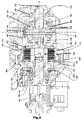
- Fig.5 is a cross-sectional view illustrating the structure of the combined coupling and differential assembly 100, taken along a plane containing a longitudinal central axis Y-Y of a pinion shaft 122 and a central axis of rotation X-X of a housing of the combined coupling and differential assembly 100.
- the housing is formed by a coupling housing 105 and a differential housing 110 which are secured together by a number of bolts 106.
- the helical ring gear 112 is fixed to a radially outer flange portion of the differential housing 110 by the same bolts 106 used to fasten the coupling and differential housings 105, 110 together.
- the combined coupling and differential assembly 100 is accommodated in the transmission housing 117 and is rotatably supported by the housing 117 for rotation about the axis of rotation X-X of the housing by means of a pair of spaced apart bearings 108, 109.
- the bearing 108 has an inner race engaged with a nose portion of the differential housing 110 and an outer race engaged with a recess 119 ( Fig.4 ) in the transmission housing 117.
- the bearing 109 has an inner race engaged with a nose portion of the coupling housing 105 and an outer race engaged with a recess 116 ( Fig.4 ) in the transmission housing 117.
- the nose on the coupling housing 105 rotatably supports a first output shaft in the form of the left hand drive shaft 101 and the nose on the differential housing 110 rotatably supports a second output shaft in the form of the right hand drive shaft 102.
- the respective axes of rotation of the pair of drive shafts 101, 102 as they exit the combined coupling and differential assembly 100, are arranged to be coaxial with the axis of rotation X-X of the housing.
- the helical ring gear 112 the coupling housing 105, the differential housing 110 and the inner ends of the drive shafts 101, 102 are all coaxially arranged for rotation about a common axis which is the central axis of rotation X-X of the housing.
- a differential 120 forming part of the combined coupling and differential assembly 100 comprises the pinion shaft 122, a pair of side gears 124, 125 and a pair of the pinion gears 121, 123 rotatably mounted on the pinion shaft 122.
- Both end portions of the pinion shaft 122 are supported by the differential housing 110 and the pinion shaft 122 is fixed to the differential housing 110 with a drive pin 150 such that the pinion shaft 122 has a longitudinal axis Y-Y arranged perpendicular to the axis of rotation X-X of the housing.
- the pinion gears 121, 123 both have outer peripheral teeth that are in meshing engagement with corresponding teeth on both of the side gears 124, 125.
- the left and right hand drive shafts 101 and 102 therefore form first and second output shafts from the combined coupling and differential assembly 100.
- a hydraulic actuation mechanism is provided for engaging and disengaging the coupling 130.
- the hydraulic actuation mechanism comprises an annular actuator piston 140 slidingly located in an annular recess 118 in the transmission housing 117, a thrust ring 137 having end portions 137a for co-operation with thrust bearings 138 located on each side of the thrust ring 137 and a thrust plate 139 to transfer force from the annular actuator piston 140, thrust ring 137 and thrust bearings 138 to the clutch plates 133.
- the thrust ring 137 is slideably supported by apertures in the coupling housing 105.
- a supply of hydraulic pressure is selectively supplied to the annular recess 118 in the transmission housing 117 from the source of hydraulic pressure 15 via the pipe or conduit 18.
- the differential side gear 124 is then connected to the left hand output shaft 101 via the clutch drum 131 and the clutch hub 135. In this state the coupling 130 is said to be 'engaged' or 'closed'.
- the differential 120 is such that it is a torque balancing device, the torque transmitted through the coupling 130 to the left hand output shaft 101 will be the same as the torque transmitted to the right hand output shaft 102 by its splined engagement with the differential side gear 125.
- any torque applied via the ring gear 112 to the differential housing 110 is distributed through the differential 120 to the front road wheels 6L, 6R because the coupling 130 in the form of the multi-plate clutch is not free to slip.
- the differential 120 acts in this case like a conventional open differential.
- the source of hydraulic power 15 may include an electronically controlled relief valve or a separate relief valve may be provided under the control of the electronic controller 16.
- the coupling 130 in this case is said to be 'dis-engaged' or 'open'.
- the differential 120 is a torque balancing device, the torque transmitted through the coupling to the left hand output shaft 101 will be the same as the torque transmitted to the right hand output shaft 102. Because there is no connection between the left hand output shaft 101 and the differential side gear 124 the torque transmitted in this case is substantially zero and so the torque transmitted to the right hand output shaft 102 is also substantially zero.
- One advantage of the invention is that it provides improved performance compared to the prior art design shown in US Patent 6,699,151 referred to above.
- Fig.6 shows in a schematic form the combined coupling and differential assembly described in US patent 6,699,151 .
- the arrow "T” represents the torque input to a housing 1 of the combined coupling and differential assembly shown in the Patent.
- a clutch 3 is interposed between the housing 1 and a carrier 2 for a differential 4.
- the differential 4 has a pinion shaft connected to the carrier 2 and rotatably supports a pair of pinion gears.
- a pair of side gears is arranged in meshing engagement with the two pinion gears.
- Each side gear is permanently drivingly connected to a respective output shaft T 01 , T 02 that provides a drive path to a respective road wheel (not shown). If the clutch 3 is disengaged then no torque can be transferred to the output shafts T 01 , T 02 because there is no drive path between the housing 1 and the carrier 2. However, when the clutch 3 is engaged to provide a drive path from the housing 1 to the carrier 2, then torque can be transferred from the housing 1 via the carrier 2 to both of the output shafts T 01 , T 02 .
- the maximum input torque at the carrier 2 cannot exceed 2000 Nm.
- the maximum torque at each output shaft T 01 , T 02 will therefore be 1000 Nm per side because the differential 4 is a torque balancing device.
- FIG.7 shows in a schematic form a combined coupling and differential assembly constructed in accordance with this invention.
- the arrow "T" represents the torque input to a housing 1 of the combined coupling and differential which in this case also forms a carrier 2 for a differential 4. That is to say, the differential 4 is driven directly by the housing 1.
- the differential 4 as before has a pinion shaft connected to the carrier 2 that rotatably supports a pair of pinion gears.
- a pair of side gears is arranged in meshing engagement with the two pinion gears.
- One of the side gears is drivingly connected to a first output shaft T 01 to provide a drive path to a respective road wheel (not shown) via a clutch 3.
- the other side gear is permanently driveably connected to a second output shaft T 02 to provide a drive path to a respective road wheel (not shown).
- the clutch 3 has a maximum torque capacity of 2000Nm, the maximum torque at each output shaft T 01 , T 02 will be limited to 2000 Nm per side due to the location of the clutch 3.
- a clutch with a capacity of 2000NM can only transmit 1000NM to each wheel whereas, in the case of the combined coupling and differential assembly constructed in accordance with the invention, the use of a clutch with a capacity of 2000 Nm allows 2000 Nm to be transmitted to each wheel.
- This provides either, a combined coupling and differential assembly with increased torque transfer capacity to each wheel for the same torque capacity clutch or the opportunity to reduce the size and torque capacity of the clutch to produce a smaller combined coupling and differential assembly for a predefined maximum wheel drive torque requirement.
Landscapes
- Engineering & Computer Science (AREA)
- General Engineering & Computer Science (AREA)
- Mechanical Engineering (AREA)
- Chemical & Material Sciences (AREA)
- Combustion & Propulsion (AREA)
- Transportation (AREA)
- Retarders (AREA)
- Arrangement And Driving Of Transmission Devices (AREA)
Abstract
Description
- This invention relates to a motor vehicle having a selectable all-wheel drive facility and, in particular, to a combined coupling and differential assembly therefor.
- It is known to provide a motor vehicle with a selectable all-wheel drive assembly.
US Patent publication 2008/0103009 for example discloses a motor vehicle having a permanent two wheel drive to a front axle of the motor vehicle and a coupling to selectively connect a rear differential to the engine so as to provide an all-wheel drive mode. - The coupling and differential in
US Patent publication 2008/0103009 are formed as separate units and are of a relatively bulky nature thereby making them difficult to package in a motor vehicle. This is particularly the case if the drive arrangement is reversed so that the rear wheels are permanently driven and drive to the front wheels is selectively connectable. -
US Patent 6,699,151 discloses a more compact arrangement in which a coupling and a differential are packaged in a single housing arranged to rotate about an axis that is common with an axis of rotation of output shafts from the differential. The coupling in the form of a multi-plate clutch is interposed between the housing and the differential and the construction is shown in schematic form inFig.6 . Although this arrangement provides a very compact assembly the inventors have realised that the performance of this arrangement can be improved upon as embodied in this invention. - It is an object of the invention to provide a combined coupling and differential assembly of compact construction with improved performance.
- According to a first aspect of the invention there is provided a combined coupling and differential assembly for a motor vehicle comprising a differential and a coupling housed in a common housing that is rotatable about a central axis of rotation by means of a ring gear drivingly attached thereto to provide a torque input to the combined coupling and differential assembly, the differential is driven directly by the common housing and comprises a pinion shaft connected to the common housing rotatably supporting a pair of pinion gears and a pair of side gears arranged in meshing engagement with the two pinion gears, each of the side gears having a respective axis of rotation arranged coaxial with the axis of rotation of the common housing and is drivingly connected to a respective output shaft wherein a first one of the pair of side gears is drivingly connectable through an engageable coupling to a first output shaft so as to provide a dis-connectable connection therebetween and a second one of the pair of side gears is drivingly connected to a second output shaft.
- The first output shaft may provide a drive path to a first road wheel of the motor vehicle and the second output shaft may provide a drive path to a second road wheel of the motor vehicle.
- The first and second road wheels may be front road wheels.
- The engageable coupling may be a friction clutch and the friction clutch may comprise a clutch drum, a clutch hub and a number of clutch plates providing a dis-connectable connection between the clutch drum and the clutch hub.
- The clutch drum may be rotatable about an axis of rotation and the axis of rotation of the clutch drum may be arranged coaxial with the axis of rotation of the common housing and the clutch hub may be rotatable about an axis of rotation and the axis of rotation of the clutch hub may be arranged coaxial with the axis of rotation of the common housing.
- The clutch drum may have a splined nose portion and the first side gear may have a splined bore for splined engagement with the nose of the clutch drum so as to provide a driving connection therebetween.
- The clutch hub may have a splined bore and the first output shaft may have a splined end portion for splined engagement with the bore of the clutch hub so as to provide a driving connection therebetween.
- The friction clutch may include a thrust ring to transfer a locking force from a hydraulic actuator to the clutch plates so as to engage the friction clutch.
- Preferably, the common housing may comprise a coupling housing and a differential housing that are secured together to form the common housing.
- The thrust ring may be slideably supported by the coupling housing.
- The second side gear may have a splined bore and the second output shaft may have a splined end portion for splined engagement with the bore of the second side gear so as to provide a driving connection therebetween.
- The first output shaft may have a respective axis of rotation arranged coaxial with the axis of rotation of the common housing and the second output shaft may have a respective axis of rotation arranged coaxial with the axis of rotation of the common housing.
- According to a second aspect of the invention there is provided a motor vehicle having an engine and a drivetrain including a combined coupling and differential assembly constructed in accordance with said first aspect of the invention.
- The motor vehicle drivetrain may include a transmission housing and the combined coupling and differential assembly may be rotatably supported by the transmission housing.
- The common housing may comprise a coupling housing and a differential housing that are secured together to form the common housing, a first bearing may be interposed between an end portion of the coupling housing and the transmission housing, a second bearing may be interposed between an end portion of the differential housing and the transmission housing and the first and second bearings in combination may rotatably support the common housing in the transmission housing.
- The engageable coupling may be a friction clutch having a number of clutch plates providing a dis-connectable connection between a clutch drum and a clutch hub and a thrust ring to transfer a locking force from a hydraulic clutch actuator to the clutch plates so as to engage the friction clutch and the transmission housing may include an annular recess connected to a source of hydraulic pressure in which is slidingly located an annular piston, the annular recess and the annular piston forming in combination the hydraulic clutch actuator.
- The invention will be described by way of example with reference to the accompanying drawing of which:
-
Fig.1 is a schematic plan view of a motor vehicle having a combined coupling and differential assembly according to the invention; -
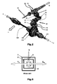
Fig.2 is an isometric view of an auxiliary drive gear system forming part of a transmission assembly for a motor vehicle showing the auxiliary drive system driving a combined coupling and differential assembly constructed in accordance with the present invention; -
Fig.3 is an isometric view on an enlarged scale of the combined coupling and differential assembly shown inFig.2 ; -
Fig.4 is a cut-away side view of the combined coupling and differential assembly shown inFig.3 in situ in a transmission casing; -
Fig.5 is a cross-section through the combined coupling and differential assembly shown inFigs. 2 to 4 ; -
Fig.6 is a schematic diagram of a prior art coupling and differential assembly; and -
Fig.7 is a schematic diagram of a combined coupling and differential assembly in accordance with the invention. - With reference to
Fig.1 , there is shown amotor vehicle 10 having anengine 11 arranged longitudinally in themotor vehicle 10. A forward direction of motion for themotor vehicle 10 is indicated by arrows "F" onFigs.1 and2 and a rear direction of motion is indicated by the arrow "R" onFig.2 . - A
transmission assembly 12 is mounted on the rear of the engine via a bell housing (not shown). Thetransmission assembly 12 is arranged with its primary drive connected torear wheels Fig 2 ) via aconventional propshaft 13 andrear axle 20 including adifferential unit 21 anddrive shafts - The
transmission assembly 12 also includes an auxiliary finaldrive gear system 14 which drives thefront wheels transmission housing 117. The auxiliaryfinal drive system 14 is arranged to drive a combined coupling anddifferential assembly 100 which selectively provides drive to thefront wheels - The left
hand drive shaft 101 has inner andouter parts 101i, 101o respectively joined together by a constant velocity oruniversal joint 103. - The right
hand drive shaft 102 has inner andouter parts 102i, 102o respectively joined together by a constant velocity oruniversal joint 103. - An electro-hydraulic actuation system for a
coupling 130 of the combined coupling anddifferential assembly 100 is provided by a source ofhydraulic power 15 controlled by anelectronic controller 16. Ahuman machine interface 17 is also provided to allow an operator of themotor vehicle 10 to select or deselect drive to thefront wheels hydraulic power 15 is connected to an actuator of the combined coupling anddifferential assembly 100 by a pipe orconduit 18 and in this case comprises a pump (not shown), a reservoir (not shown) and one or more electro-hydraulic valves (not shown) controlled by theelectronic controller 16. - With particular reference to
Fig.2 , aninput shaft 30 from a clutch (not shown) interposed between theengine 10 and thetransmission assembly 12 drives themain shaft 35. The auxiliary drive for thefront wheels main shaft 35 via the auxiliary finaldrive gear system 14 which includes atransfer gear 37 that meshes with agear 36 rotatable with themain shaft 35. Thetransfer gear 37 is mounted on ashaft 38 and meshes with a drivengear 41 mounted on ashaft 40. Theshaft 40 has abevel gear 42 mounted fast on the opposite end to the drivengear 41. Asecond bevel gear 52 and ahelical pinion gear 51 are fixed fast on atransverse shaft 50. Thebevel gear 42 is meshed with thesecond bevel gear 52 so as to drive the transverse shaft and hence thehelical pinion gear 51. - The
helical pinion gear 51 meshes with ahelical ring gear 112 fastened to adifferential casing 110 of the combined coupling anddifferential assembly 100 so as to provide a continuous drive from themain shaft 35 to the combined coupling anddifferential assembly 100. - The
transverse shaft 50 is arranged parallel to a transverse axis X-X about which thedifferential casing 110 andhelical ring gear 112 rotate. - When the
motor vehicle 10 is driving normally along a road, the primary drive is through thedifferential 21 and backaxle 20. Anengageable coupling 130 of the combined coupling anddifferential assembly 100 is in this case in a disengaged state and thefront wheels differential assembly 100 to thefront wheels - If in a particular situation, the
rear wheels engageable coupling 130 of the combined coupling anddifferential assembly 100 can be engaged either automatically by theelectronic controller 16 or via a user of themotor vehicle 10 using thehuman machine interface 17 depending upon the configuration and construction of themotor vehicle 10. When theengageable coupling 130 of the combined coupling anddifferential assembly 100 is engaged, drive is transmitted, as will be described in more detail hereinafter, to thefront wheels engine 11 via thetransmission assembly 12, auxiliary finaldrive gear system 14 and front drive shafts 101,102 so as to supplement the drive from therear wheels - With particular reference to
Figs.2 to 5 , the combined coupling anddifferential assembly 100 shown inFig.1 will be described in more detail. -
Fig.5 is a cross-sectional view illustrating the structure of the combined coupling anddifferential assembly 100, taken along a plane containing a longitudinal central axis Y-Y of apinion shaft 122 and a central axis of rotation X-X of a housing of the combined coupling anddifferential assembly 100. - The housing is formed by a
coupling housing 105 and adifferential housing 110 which are secured together by a number ofbolts 106. Thehelical ring gear 112 is fixed to a radially outer flange portion of thedifferential housing 110 by thesame bolts 106 used to fasten the coupling anddifferential housings - The combined coupling and
differential assembly 100 is accommodated in thetransmission housing 117 and is rotatably supported by thehousing 117 for rotation about the axis of rotation X-X of the housing by means of a pair of spacedapart bearings - The
bearing 108 has an inner race engaged with a nose portion of thedifferential housing 110 and an outer race engaged with a recess 119 (Fig.4 ) in thetransmission housing 117. Thebearing 109 has an inner race engaged with a nose portion of thecoupling housing 105 and an outer race engaged with a recess 116 (Fig.4 ) in thetransmission housing 117. - The nose on the
coupling housing 105 rotatably supports a first output shaft in the form of the lefthand drive shaft 101 and the nose on thedifferential housing 110 rotatably supports a second output shaft in the form of the righthand drive shaft 102. - The respective axes of rotation of the pair of
drive shafts differential assembly 100, are arranged to be coaxial with the axis of rotation X-X of the housing. - Therefore the
helical ring gear 112, thecoupling housing 105, thedifferential housing 110 and the inner ends of thedrive shafts - It will be appreciated that if constant velocity joints or universal joints such as those shown on
Fig.1 are fitted to thedrive shafts Fig.1 ) of the drive shafts 101,102 outboard of these joints (103 onFig.1 ) may not correspond to the axes of rotation of the portions (101i, 102i onFig.1 ) of thedrive shafts Fig.1 ) where they enter the combined coupling anddifferential assembly 100. - A differential 120 forming part of the combined coupling and
differential assembly 100 comprises thepinion shaft 122, a pair of side gears 124, 125 and a pair of the pinion gears 121, 123 rotatably mounted on thepinion shaft 122. - Both end portions of the
pinion shaft 122 are supported by thedifferential housing 110 and thepinion shaft 122 is fixed to thedifferential housing 110 with adrive pin 150 such that thepinion shaft 122 has a longitudinal axis Y-Y arranged perpendicular to the axis of rotation X-X of the housing. - The pair of side gears 124, 125 is disposed such that they are opposed to each other on opposite sides of the
pinion shaft 122 and are accommodated within thedifferential housing 110 with the pinion gears 121, 123 and thepinion shaft 122. Furthermore, the side gears 124, 125 are disposed rotatably about an axis that is coaxial with the axis of rotation X-X of the housing and, in particular, coaxial with the axis of rotation of thedifferential housing 110. - The pinion gears 121, 123 are rotatably supported by the
pinion shaft 122 and rotate with thepinion shaft 122 when thedifferential housing 110 is rotated about its axis of rotation. - The pinion gears 121, 123 both have outer peripheral teeth that are in meshing engagement with corresponding teeth on both of the side gears 124, 125.
- The right
hand side gear 125 has an internalsplined bore 127 that provides a driving connection to the rightfront drive shaft 102 which includes a complementary splined end portion. - The left
hand side gear 124 has an internalsplined bore 126 engaged with a complementary spline formed on anose portion 132 of aclutch drum 131. Athrust bearing 141 is interposed between theclutch drum 131 and thedifferential housing 110. Theclutch drum 131 has an outercylindrical rim portion 134 having a castellated or splined inner surface for providing a driving connection between theclutch drum 131 and aclutch hub 135 by means of a number ofclutch plates 133 interposed therebetween. Alternate outer and innerclutch plates 133 are respectively engaged with therim portion 134 and theclutch hub 135. Theclutch hub 135 has an external castellated orsplined surface 136a for providing a driving connection between theclutch drum 131 and the inner clutch plates with which it co-operates. - Therefore in this case the
coupling 130 forming part of the combined coupling anddifferential assembly 100 is in the form of a conventional multi-plate clutch assembly comprising theclutch drum 131, theclutch hub 135 and theclutch plates 133. - The
clutch hub 135 has asplined bore 136b for co-operation with complementary splines formed on an inner end portion of the lefthand drive shaft 101 so as to form a driving connection therebetween. - The left and right
hand drive shafts differential assembly 100. - A hydraulic actuation mechanism is provided for engaging and disengaging the
coupling 130. The hydraulic actuation mechanism comprises anannular actuator piston 140 slidingly located in anannular recess 118 in thetransmission housing 117, athrust ring 137 havingend portions 137a for co-operation withthrust bearings 138 located on each side of thethrust ring 137 and athrust plate 139 to transfer force from theannular actuator piston 140, thrustring 137 and thrustbearings 138 to theclutch plates 133. Thethrust ring 137 is slideably supported by apertures in thecoupling housing 105. - A supply of hydraulic pressure is selectively supplied to the
annular recess 118 in thetransmission housing 117 from the source ofhydraulic pressure 15 via the pipe orconduit 18. - Operation of the combined coupling and
differential assembly 100 is as follows, when external pressure is applied from the source ofhydraulic pressure 15 theannular recess 118 in thetransmission cover 117 is pressurised and forces theannular actuator piston 140 out thereby forcing the inner and outerclutch plates 133 together so as to clamp them together and form a driving connection between theclutch hub 135 and theside gear 124. - The
differential side gear 124 is then connected to the lefthand output shaft 101 via theclutch drum 131 and theclutch hub 135. In this state thecoupling 130 is said to be 'engaged' or 'closed'. - Because the arrangement of the differential 120 is such that it is a torque balancing device, the torque transmitted through the
coupling 130 to the lefthand output shaft 101 will be the same as the torque transmitted to the righthand output shaft 102 by its splined engagement with thedifferential side gear 125. - Therefore any torque applied via the
ring gear 112 to thedifferential housing 110 is distributed through the differential 120 to thefront road wheels coupling 130 in the form of the multi-plate clutch is not free to slip. The differential 120 acts in this case like a conventional open differential. - When the external pressure is released in response to a controlling signal from the
electronic controller 16, the pressure in theannular recess 118 will decay and this allows theannular piston 140 to return or retract into theannular recess 118. It will be appreciated that the source ofhydraulic power 15 may include an electronically controlled relief valve or a separate relief valve may be provided under the control of theelectronic controller 16. - When the
piston 140 retracts this allows the inner and outerclutch plates 133 to move apart thereby breaking the drive path through thecoupling 130. Thedifferential side gear 124 is thereby disconnected from the lefthand output shaft 101. Thecoupling 130 in this case is said to be 'dis-engaged' or 'open'. - As before, because the differential 120 is a torque balancing device, the torque transmitted through the coupling to the left
hand output shaft 101 will be the same as the torque transmitted to the righthand output shaft 102. Because there is no connection between the lefthand output shaft 101 and thedifferential side gear 124 the torque transmitted in this case is substantially zero and so the torque transmitted to the righthand output shaft 102 is also substantially zero. - Therefore any torque applied via the
ring gear 112 to thedifferential housing 110 will not be distributed through the differential 120 to thefront road wheels coupling 130 is free to slip. - Although the invention has been applied with respect to a combined coupling and differential assembly used to selectively connect the front wheels of a motor vehicle to form an all-wheel drive vehicle it will be appreciated that it could also be used to selectively connect rear wheels of a motor vehicle if the front wheels are permanently driven.
- One advantage of the invention is that it provides improved performance compared to the prior art design shown in
US Patent 6,699,151 referred to above. -
Fig.6 shows in a schematic form the combined coupling and differential assembly described inUS patent 6,699,151 . - The arrow "T" represents the torque input to a
housing 1 of the combined coupling and differential assembly shown in the Patent. Aclutch 3 is interposed between thehousing 1 and acarrier 2 for a differential 4. The differential 4 has a pinion shaft connected to thecarrier 2 and rotatably supports a pair of pinion gears. A pair of side gears is arranged in meshing engagement with the two pinion gears. Each side gear is permanently drivingly connected to a respective output shaft T01, T02 that provides a drive path to a respective road wheel (not shown). If theclutch 3 is disengaged then no torque can be transferred to the output shafts T01, T02 because there is no drive path between thehousing 1 and thecarrier 2. However, when theclutch 3 is engaged to provide a drive path from thehousing 1 to thecarrier 2, then torque can be transferred from thehousing 1 via thecarrier 2 to both of the output shafts T01, T02. - If the
clutch 3 is engaged and the torque capacity of the clutch 3 is 2000 Nm, then the maximum input torque at thecarrier 2 cannot exceed 2000 Nm. The maximum torque at each output shaft T01, T02 will therefore be 1000 Nm per side because the differential 4 is a torque balancing device. - Referring now to
Fig.7 which shows in a schematic form a combined coupling and differential assembly constructed in accordance with this invention. - The arrow "T" represents the torque input to a
housing 1 of the combined coupling and differential which in this case also forms acarrier 2 for a differential 4. That is to say, the differential 4 is driven directly by thehousing 1. - The differential 4 as before has a pinion shaft connected to the
carrier 2 that rotatably supports a pair of pinion gears. A pair of side gears is arranged in meshing engagement with the two pinion gears. - One of the side gears is drivingly connected to a first output shaft T01 to provide a drive path to a respective road wheel (not shown) via a
clutch 3. The other side gear is permanently driveably connected to a second output shaft T02 to provide a drive path to a respective road wheel (not shown). - If the
clutch 3 is disengaged no torque can be transmitted to the road wheels. This is because the torque that can be transmitted to the first output shaft T01 will be substantially zero due to the disengaged state of theclutch 3 and, because the differential 4 is a torque balancing device, the torque supplied to the second output shaft T02 must therefore also be substantially zero. - With this arrangement, if the
clutch 3 is engaged and the torque capacity of the clutch 3 is, as forFig.6 , 2000 Nm, then the maximum input torque at thehousing 1 must not exceed 4000 Nm. This is because the maximum torque for the first output shaft T01 is 2000NM and the maximum torque for the second output shaft T02 must be the same because the differential 4 is a torque balancing device. - Therefore, if the
clutch 3 has a maximum torque capacity of 2000Nm, the maximum torque at each output shaft T01, T02 will be limited to 2000 Nm per side due to the location of theclutch 3. - Therefore, in the case of the prior art combined coupling and differential assembly shown in
Fig.6 , a clutch with a capacity of 2000NM can only transmit 1000NM to each wheel whereas, in the case of the combined coupling and differential assembly constructed in accordance with the invention, the use of a clutch with a capacity of 2000 Nm allows 2000 Nm to be transmitted to each wheel. - This provides either, a combined coupling and differential assembly with increased torque transfer capacity to each wheel for the same torque capacity clutch or the opportunity to reduce the size and torque capacity of the clutch to produce a smaller combined coupling and differential assembly for a predefined maximum wheel drive torque requirement.
- It will be appreciated by those skilled in the art that although the invention has been described by way of example with reference to one or more embodiments it is not limited to the disclosed embodiments and that alternative embodiments could be constructed without departing from the scope of the invention as defined by the appended claims.
Claims (15)
- A combined coupling and differential assembly (100) for a motor vehicle (10) comprising a differential and a coupling housed in a common housing (105, 110) that is rotatable about a central axis of rotation (X-X) by means of a ring gear (112) drivingly attached thereto to provide a torque input to the combined coupling and differential assembly (100), the differential is driven directly by the common housing (105, 110) and comprises a pinion shaft (122) connected to the common housing (105,110) rotatably supporting a pair of pinion gears (121, 123) and a pair of side gears (124, 125) arranged in meshing engagement with the two pinion gears (121, 123), each of the side gears (124, 125) having a respective axis of rotation arranged coaxial with the axis of rotation (X-X) of the common housing (105, 110) and is drivingly connected to a respective output shaft (101, 102) characterised in that a first one (124) of the pair of side gears (124, 125) is drivingly connectable through an engageable coupling (131, 133, 135) to a first output shaft 101 so as to provide a dis-connectable connection therebetween and a second one (125) of the pair of side gears (124, 125) is drivingly connected to a second output shaft (102).
- An assembly as claimed in claim 1 wherein the first output shaft (101) provides a drive path to a first road wheel (6L) of the motor vehicle (10) and the second output shaft (102) provides a drive path to a second road wheel (6R) of the motor vehicle (10).
- An assembly as claimed in claim 1 or in claim 2
wherein the engageable coupling is a friction clutch and the friction clutch comprises a clutch drum(131), a clutch hub (135) and a number of clutch plates (133) providing a dis-connectable connection between the clutch drum (131) and the clutch hub (135). - An assembly as claimed in claim 3 wherein the clutch drum (131) is rotatable about an axis of rotation and the axis of rotation of the clutch drum (131) is arranged coaxial with the axis of rotation (X-X) of the common housing 105, 110) and the clutch hub (135) is rotatable about an axis of rotation and the axis of rotation of the clutch hub (135) is arranged coaxial with the axis of rotation (X-X) of the common housing (105, 110).
- An assembly as claimed in claim 3 or in claim 4
wherein the clutch drum (131) has a splined nose portion (132) and the first side gear (124) has a splined bore (126) for splined engagement with the nose (132) of the clutch drum (131) so as to provide a driving connection therebetween. - An assembly as claimed in any of claims 3 to 5
wherein the clutch hub (135) has a splined bore (136b) and the first output shaft (101) has a splined end portion for splined engagement with the bore (136b) of the clutch hub (135) so as to provide a driving connection therebetween. - An assembly as claimed in any of claims 3 to 6
wherein the friction clutch includes a thrust ring (137) to transfer a locking force from a hydraulic actuator (118, 140) to the clutch plates (133) so as to engage the friction clutch. - An assembly as claimed in any of claims 1 to 7
wherein the common housing comprises a coupling housing (105) and a differential housing (110) that are secured together to form the common housing. - An assembly as claimed in claim 8 when dependent upon claim 8 wherein the thrust ring (137) is slideably supported by the coupling housing (105).
- An assembly as claimed in any of claims 1 to 9
wherein the second side gear (125) has a splined bore and the second output shaft (102) has a splined end portion for splined engagement with the bore of the second side gear (125) so as to provide a driving connection therebetween. - An assembly as claimed in any of claims 1 to 10
wherein the first output shaft (101) has a respective axis of rotation arranged coaxial with the axis of rotation (X-X) of the common housing (105, 110) and the second output shaft (102) has a respective axis of rotation arranged coaxial with the axis of rotation (X-X) of the common housing (105, 110). - A motor vehicle having an engine and a drivetrain including a combined coupling and differential assembly as claimed in any of claims 1 to 11.
- A motor vehicle as claimed in claim 12 wherein the motor vehicle drivetrain includes a transmission housing (117) and the combined coupling and differential assembly (100) is rotatably supported by the transmission housing (117).
- A motor vehicle as claimed in claim 12 or in claim 13 wherein the common housing comprises a coupling housing (105) and a differential housing (110) that are secured together to form the common housing, a first bearing (109) is interposed between an end portion of the coupling housing (105) and the transmission housing (117), a second bearing (108) is interposed between an end portion of the differential housing (110) and the transmission housing (117) and the first and second bearings (109 and 108) in combination rotatably support the common housing (105, 110) in the transmission housing (117).
- A motor vehicle as claimed in claim 13 or in claim 14 when dependent upon claim 13 wherein the engageable coupling is a friction clutch having a number of clutch plates (133) providing a dis-connectable connection between a clutch drum (131) and a clutch hub (135) and a thrust ring (137) to transfer a locking force from a hydraulic clutch actuator (118, 140) to the clutch plates (133) so as to engage the friction clutch and the transmission housing (117) includes an annular recess (118) connected to a source of hydraulic pressure in which is slidingly located an annular piston (140), the annular recess (118) and the annular piston (140) forming in combination the hydraulic clutch actuator.
Applications Claiming Priority (1)
| Application Number | Priority Date | Filing Date | Title |
|---|---|---|---|
| GB1320810.3A GB2521594B (en) | 2013-11-26 | 2013-11-26 | A combined coupling and differential assembly |
Publications (2)
| Publication Number | Publication Date |
|---|---|
| EP2876332A1 true EP2876332A1 (en) | 2015-05-27 |
| EP2876332B1 EP2876332B1 (en) | 2020-07-29 |
Family
ID=49918190
Family Applications (1)
| Application Number | Title | Priority Date | Filing Date |
|---|---|---|---|
| EP14275232.8A Active EP2876332B1 (en) | 2013-11-26 | 2014-11-12 | A combined coupling and differential assembly |
Country Status (3)
| Country | Link |
|---|---|
| EP (1) | EP2876332B1 (en) |
| CN (1) | CN204327902U (en) |
| GB (1) | GB2521594B (en) |
Cited By (3)
| Publication number | Priority date | Publication date | Assignee | Title |
|---|---|---|---|---|
| US10502308B2 (en) | 2016-12-22 | 2019-12-10 | Polaris Industries Inc. | Driveline for powersports vehicle |
| CN112534161A (en) * | 2018-04-16 | 2021-03-19 | 莱纳玛公司 | Differential disconnect assembly |
| WO2023198803A1 (en) * | 2022-04-14 | 2023-10-19 | Valeo Embrayages | Differential drive device |
Families Citing this family (6)
| Publication number | Priority date | Publication date | Assignee | Title |
|---|---|---|---|---|
| DE102015112102A1 (en) * | 2015-07-24 | 2017-01-26 | Gkn Driveline International Gmbh | Coupling module for a drive train and drive arrangement with a coupling module |
| SE539976C2 (en) * | 2016-06-22 | 2018-02-20 | Scania Cv Ab | An inter-axle differential assembly, a driving axle assembly and a motor vehicle |
| CN109641518B (en) * | 2016-07-14 | 2022-12-13 | 伊顿智能动力有限公司 | Hydraulic control unit with differential connection |
| CN108825749A (en) * | 2018-06-06 | 2018-11-16 | 珠海市万顺睿通科技有限公司 | A kind of differential mechanism for water treatment facilities |
| DE102019203015A1 (en) * | 2019-03-06 | 2020-09-10 | Zf Friedrichshafen Ag | Differential gears of a motor vehicle |
| CN112178153B (en) * | 2020-09-30 | 2021-12-03 | 大连理工大学 | Under-actuated device using differential and friction clutch |
Citations (4)
| Publication number | Priority date | Publication date | Assignee | Title |
|---|---|---|---|---|
| US6296590B1 (en) * | 2000-01-27 | 2001-10-02 | Gkn Automotive, Inc. | Torque distribution device |
| US6699151B2 (en) | 2002-03-27 | 2004-03-02 | Torque-Traction Technologies, Inc. | Solenoid valve controlled all-wheel drive hydraulic coupling assembly |
| US20080103009A1 (en) | 2006-10-31 | 2008-05-01 | Jungho Park | Self-contained torque-coupling assembly |
| WO2011016950A2 (en) * | 2009-08-07 | 2011-02-10 | American Axle & Manufacturing, Inc. | Motor vehicle with disconnectable all-wheel drive system |
Family Cites Families (4)
| Publication number | Priority date | Publication date | Assignee | Title |
|---|---|---|---|---|
| JP4376745B2 (en) * | 2004-09-24 | 2009-12-02 | 本田技研工業株式会社 | Driving force distribution device for four-wheel drive vehicle |
| JP5728861B2 (en) * | 2010-09-15 | 2015-06-03 | 株式会社ジェイテクト | Four-wheel drive vehicle and its control device |
| GB2490491B (en) * | 2011-04-28 | 2014-08-06 | Jaguar Land Rover Ltd | Vehicle and method of controlling a vehicle |
| WO2014011230A1 (en) * | 2012-07-09 | 2014-01-16 | Eaton Corporation | Clutch system |
-
2013
- 2013-11-26 GB GB1320810.3A patent/GB2521594B/en active Active
-
2014
- 2014-11-12 EP EP14275232.8A patent/EP2876332B1/en active Active
- 2014-11-26 CN CN201420722257.3U patent/CN204327902U/en not_active Expired - Lifetime
Patent Citations (4)
| Publication number | Priority date | Publication date | Assignee | Title |
|---|---|---|---|---|
| US6296590B1 (en) * | 2000-01-27 | 2001-10-02 | Gkn Automotive, Inc. | Torque distribution device |
| US6699151B2 (en) | 2002-03-27 | 2004-03-02 | Torque-Traction Technologies, Inc. | Solenoid valve controlled all-wheel drive hydraulic coupling assembly |
| US20080103009A1 (en) | 2006-10-31 | 2008-05-01 | Jungho Park | Self-contained torque-coupling assembly |
| WO2011016950A2 (en) * | 2009-08-07 | 2011-02-10 | American Axle & Manufacturing, Inc. | Motor vehicle with disconnectable all-wheel drive system |
Cited By (8)
| Publication number | Priority date | Publication date | Assignee | Title |
|---|---|---|---|---|
| US10502308B2 (en) | 2016-12-22 | 2019-12-10 | Polaris Industries Inc. | Driveline for powersports vehicle |
| US11313452B2 (en) | 2016-12-22 | 2022-04-26 | Polaris Industries Inc. | Driveline for powersports vehicle |
| US11624435B2 (en) | 2016-12-22 | 2023-04-11 | Polaris Industries Inc. | Driveline for powersports vehicle |
| US12253158B2 (en) | 2016-12-22 | 2025-03-18 | Polaris Industries Inc. | Driveline for powersports vehicle |
| CN112534161A (en) * | 2018-04-16 | 2021-03-19 | 莱纳玛公司 | Differential disconnect assembly |
| WO2023198803A1 (en) * | 2022-04-14 | 2023-10-19 | Valeo Embrayages | Differential drive device |
| FR3134608A1 (en) * | 2022-04-14 | 2023-10-20 | Valeo Embrayages | Differential drive device |
| US12607254B2 (en) | 2022-04-14 | 2026-04-21 | Valeo Embrayages | Differential drive device |
Also Published As
| Publication number | Publication date |
|---|---|
| GB2521594A (en) | 2015-07-01 |
| GB201320810D0 (en) | 2014-01-08 |
| GB2521594B (en) | 2019-11-13 |
| EP2876332B1 (en) | 2020-07-29 |
| CN204327902U (en) | 2015-05-13 |
Similar Documents
| Publication | Publication Date | Title |
|---|---|---|
| EP2876332B1 (en) | A combined coupling and differential assembly | |
| EP0262434B1 (en) | Interaxle differential restriction device for vehicle four wheel drive systems | |
| US9777818B2 (en) | Two-speed drive module | |
| EP2440804B1 (en) | Compact transfer case with beveloid gearset | |
| US6827663B2 (en) | Differential gear | |
| US20160138695A1 (en) | Disconnecting awd driveline with torque-vectoring capabilities | |
| US9346354B2 (en) | Disconnecting driveline component | |
| US7452301B2 (en) | Externally actuated torque coupling for drivetrain | |
| EP2161155A2 (en) | Power take-off unit with active coupling and hypoid disconnect system | |
| KR20110117094A (en) | AHD vehicle with disconnect system | |
| CN106740091B (en) | Disconnected all-wheel drive transmission system with flat towing capacity | |
| CN102341261A (en) | All-wheel drive with active dry disconnect system | |
| US10066723B2 (en) | Driveline disconnect with modular rear driveline module (RDM) with integrated coupling and differential control | |
| US9586477B2 (en) | Front wheel drive based power transfer unit (PTU) with hydraulically actuated disconnect | |
| EP3475114B1 (en) | An inter-axle differential assembly, a driving axle assembly and a motor vehicle | |
| JP6213449B2 (en) | Vehicle drive device | |
| US10479198B2 (en) | Transfer case with active clutch on front output and pass-thru rear output | |
| JPS6349526A (en) | Power transmission mechanism for vehicle | |
| US9248738B2 (en) | Power transfer unit for AWD vehicles having integrated joint assembly | |
| GB2274320A (en) | An electromagnetic clutch driven steerable drive axle for a four wheel drive vehicle | |
| JPS6320580Y2 (en) | ||
| JP4399349B2 (en) | Four-wheel drive system for vehicles | |
| WO2018051456A1 (en) | Power transmission device | |
| WO2010144304A1 (en) | Power transfer unit with output shaft having integrated joint assembly | |
| GB2630126A (en) | Combined coupling and differential assemblies |
Legal Events
| Date | Code | Title | Description |
|---|---|---|---|
| PUAI | Public reference made under article 153(3) epc to a published international application that has entered the european phase |
Free format text: ORIGINAL CODE: 0009012 |
|
| 17P | Request for examination filed |
Effective date: 20141112 |
|
| AK | Designated contracting states |
Kind code of ref document: A1 Designated state(s): AL AT BE BG CH CY CZ DE DK EE ES FI FR GB GR HR HU IE IS IT LI LT LU LV MC MK MT NL NO PL PT RO RS SE SI SK SM TR |
|
| AX | Request for extension of the european patent |
Extension state: BA ME |
|
| R17P | Request for examination filed (corrected) |
Effective date: 20151109 |
|
| 17Q | First examination report despatched |
Effective date: 20160727 |
|
| GRAP | Despatch of communication of intention to grant a patent |
Free format text: ORIGINAL CODE: EPIDOSNIGR1 |
|
| STAA | Information on the status of an ep patent application or granted ep patent |
Free format text: STATUS: GRANT OF PATENT IS INTENDED |
|
| INTG | Intention to grant announced |
Effective date: 20200212 |
|
| RIN1 | Information on inventor provided before grant (corrected) |
Inventor name: MAY, ERIC Inventor name: MATHER, JOHN |
|
| GRAS | Grant fee paid |
Free format text: ORIGINAL CODE: EPIDOSNIGR3 |
|
| GRAA | (expected) grant |
Free format text: ORIGINAL CODE: 0009210 |
|
| STAA | Information on the status of an ep patent application or granted ep patent |
Free format text: STATUS: THE PATENT HAS BEEN GRANTED |
|
| AK | Designated contracting states |
Kind code of ref document: B1 Designated state(s): AL AT BE BG CH CY CZ DE DK EE ES FI FR GB GR HR HU IE IS IT LI LT LU LV MC MK MT NL NO PL PT RO RS SE SI SK SM TR |
|
| REG | Reference to a national code |
Ref country code: CH Ref legal event code: EP |
|
| REG | Reference to a national code |
Ref country code: AT Ref legal event code: REF Ref document number: 1296180 Country of ref document: AT Kind code of ref document: T Effective date: 20200815 |
|
| REG | Reference to a national code |
Ref country code: IE Ref legal event code: FG4D |
|
| REG | Reference to a national code |
Ref country code: DE Ref legal event code: R096 Ref document number: 602014068232 Country of ref document: DE |
|
| REG | Reference to a national code |
Ref country code: LT Ref legal event code: MG4D |
|
| REG | Reference to a national code |
Ref country code: NL Ref legal event code: MP Effective date: 20200729 |
|
| REG | Reference to a national code |
Ref country code: DE Ref legal event code: R082 Ref document number: 602014068232 Country of ref document: DE Representative=s name: HL KEMPNER PATENTANWAELTE, SOLICITORS (ENGLAND, DE Ref country code: DE Ref legal event code: R082 Ref document number: 602014068232 Country of ref document: DE Representative=s name: HL KEMPNER PATENTANWALT, RECHTSANWALT, SOLICIT, DE Ref country code: DE Ref legal event code: R082 Ref document number: 602014068232 Country of ref document: DE Representative=s name: HL KEMPNER PARTG MBB, DE |
|
| REG | Reference to a national code |
Ref country code: AT Ref legal event code: MK05 Ref document number: 1296180 Country of ref document: AT Kind code of ref document: T Effective date: 20200729 |
|
| PG25 | Lapsed in a contracting state [announced via postgrant information from national office to epo] |
Ref country code: FI Free format text: LAPSE BECAUSE OF FAILURE TO SUBMIT A TRANSLATION OF THE DESCRIPTION OR TO PAY THE FEE WITHIN THE PRESCRIBED TIME-LIMIT Effective date: 20200729 Ref country code: PT Free format text: LAPSE BECAUSE OF FAILURE TO SUBMIT A TRANSLATION OF THE DESCRIPTION OR TO PAY THE FEE WITHIN THE PRESCRIBED TIME-LIMIT Effective date: 20201130 Ref country code: SE Free format text: LAPSE BECAUSE OF FAILURE TO SUBMIT A TRANSLATION OF THE DESCRIPTION OR TO PAY THE FEE WITHIN THE PRESCRIBED TIME-LIMIT Effective date: 20200729 Ref country code: HR Free format text: LAPSE BECAUSE OF FAILURE TO SUBMIT A TRANSLATION OF THE DESCRIPTION OR TO PAY THE FEE WITHIN THE PRESCRIBED TIME-LIMIT Effective date: 20200729 Ref country code: GR Free format text: LAPSE BECAUSE OF FAILURE TO SUBMIT A TRANSLATION OF THE DESCRIPTION OR TO PAY THE FEE WITHIN THE PRESCRIBED TIME-LIMIT Effective date: 20201030 Ref country code: ES Free format text: LAPSE BECAUSE OF FAILURE TO SUBMIT A TRANSLATION OF THE DESCRIPTION OR TO PAY THE FEE WITHIN THE PRESCRIBED TIME-LIMIT Effective date: 20200729 Ref country code: LT Free format text: LAPSE BECAUSE OF FAILURE TO SUBMIT A TRANSLATION OF THE DESCRIPTION OR TO PAY THE FEE WITHIN THE PRESCRIBED TIME-LIMIT Effective date: 20200729 Ref country code: BG Free format text: LAPSE BECAUSE OF FAILURE TO SUBMIT A TRANSLATION OF THE DESCRIPTION OR TO PAY THE FEE WITHIN THE PRESCRIBED TIME-LIMIT Effective date: 20201029 Ref country code: AT Free format text: LAPSE BECAUSE OF FAILURE TO SUBMIT A TRANSLATION OF THE DESCRIPTION OR TO PAY THE FEE WITHIN THE PRESCRIBED TIME-LIMIT Effective date: 20200729 Ref country code: NO Free format text: LAPSE BECAUSE OF FAILURE TO SUBMIT A TRANSLATION OF THE DESCRIPTION OR TO PAY THE FEE WITHIN THE PRESCRIBED TIME-LIMIT Effective date: 20201029 |
|
| PG25 | Lapsed in a contracting state [announced via postgrant information from national office to epo] |
Ref country code: IS Free format text: LAPSE BECAUSE OF FAILURE TO SUBMIT A TRANSLATION OF THE DESCRIPTION OR TO PAY THE FEE WITHIN THE PRESCRIBED TIME-LIMIT Effective date: 20201129 Ref country code: LV Free format text: LAPSE BECAUSE OF FAILURE TO SUBMIT A TRANSLATION OF THE DESCRIPTION OR TO PAY THE FEE WITHIN THE PRESCRIBED TIME-LIMIT Effective date: 20200729 Ref country code: PL Free format text: LAPSE BECAUSE OF FAILURE TO SUBMIT A TRANSLATION OF THE DESCRIPTION OR TO PAY THE FEE WITHIN THE PRESCRIBED TIME-LIMIT Effective date: 20200729 Ref country code: RS Free format text: LAPSE BECAUSE OF FAILURE TO SUBMIT A TRANSLATION OF THE DESCRIPTION OR TO PAY THE FEE WITHIN THE PRESCRIBED TIME-LIMIT Effective date: 20200729 |
|
| PG25 | Lapsed in a contracting state [announced via postgrant information from national office to epo] |
Ref country code: NL Free format text: LAPSE BECAUSE OF FAILURE TO SUBMIT A TRANSLATION OF THE DESCRIPTION OR TO PAY THE FEE WITHIN THE PRESCRIBED TIME-LIMIT Effective date: 20200729 |
|
| PG25 | Lapsed in a contracting state [announced via postgrant information from national office to epo] |
Ref country code: SM Free format text: LAPSE BECAUSE OF FAILURE TO SUBMIT A TRANSLATION OF THE DESCRIPTION OR TO PAY THE FEE WITHIN THE PRESCRIBED TIME-LIMIT Effective date: 20200729 Ref country code: RO Free format text: LAPSE BECAUSE OF FAILURE TO SUBMIT A TRANSLATION OF THE DESCRIPTION OR TO PAY THE FEE WITHIN THE PRESCRIBED TIME-LIMIT Effective date: 20200729 Ref country code: IT Free format text: LAPSE BECAUSE OF FAILURE TO SUBMIT A TRANSLATION OF THE DESCRIPTION OR TO PAY THE FEE WITHIN THE PRESCRIBED TIME-LIMIT Effective date: 20200729 Ref country code: EE Free format text: LAPSE BECAUSE OF FAILURE TO SUBMIT A TRANSLATION OF THE DESCRIPTION OR TO PAY THE FEE WITHIN THE PRESCRIBED TIME-LIMIT Effective date: 20200729 Ref country code: DK Free format text: LAPSE BECAUSE OF FAILURE TO SUBMIT A TRANSLATION OF THE DESCRIPTION OR TO PAY THE FEE WITHIN THE PRESCRIBED TIME-LIMIT Effective date: 20200729 Ref country code: CZ Free format text: LAPSE BECAUSE OF FAILURE TO SUBMIT A TRANSLATION OF THE DESCRIPTION OR TO PAY THE FEE WITHIN THE PRESCRIBED TIME-LIMIT Effective date: 20200729 |
|
| REG | Reference to a national code |
Ref country code: DE Ref legal event code: R097 Ref document number: 602014068232 Country of ref document: DE |
|
| PG25 | Lapsed in a contracting state [announced via postgrant information from national office to epo] |
Ref country code: AL Free format text: LAPSE BECAUSE OF FAILURE TO SUBMIT A TRANSLATION OF THE DESCRIPTION OR TO PAY THE FEE WITHIN THE PRESCRIBED TIME-LIMIT Effective date: 20200729 |
|
| PLBE | No opposition filed within time limit |
Free format text: ORIGINAL CODE: 0009261 |
|
| STAA | Information on the status of an ep patent application or granted ep patent |
Free format text: STATUS: NO OPPOSITION FILED WITHIN TIME LIMIT |
|
| PG25 | Lapsed in a contracting state [announced via postgrant information from national office to epo] |
Ref country code: SK Free format text: LAPSE BECAUSE OF FAILURE TO SUBMIT A TRANSLATION OF THE DESCRIPTION OR TO PAY THE FEE WITHIN THE PRESCRIBED TIME-LIMIT Effective date: 20200729 Ref country code: MC Free format text: LAPSE BECAUSE OF FAILURE TO SUBMIT A TRANSLATION OF THE DESCRIPTION OR TO PAY THE FEE WITHIN THE PRESCRIBED TIME-LIMIT Effective date: 20200729 |
|
| REG | Reference to a national code |
Ref country code: CH Ref legal event code: PL |
|
| 26N | No opposition filed |
Effective date: 20210430 |
|
| GBPC | Gb: european patent ceased through non-payment of renewal fee |
Effective date: 20201112 |
|
| PG25 | Lapsed in a contracting state [announced via postgrant information from national office to epo] |
Ref country code: LU Free format text: LAPSE BECAUSE OF NON-PAYMENT OF DUE FEES Effective date: 20201112 |
|
| REG | Reference to a national code |
Ref country code: BE Ref legal event code: MM Effective date: 20201130 |
|
| PG25 | Lapsed in a contracting state [announced via postgrant information from national office to epo] |
Ref country code: LI Free format text: LAPSE BECAUSE OF NON-PAYMENT OF DUE FEES Effective date: 20201130 Ref country code: SI Free format text: LAPSE BECAUSE OF FAILURE TO SUBMIT A TRANSLATION OF THE DESCRIPTION OR TO PAY THE FEE WITHIN THE PRESCRIBED TIME-LIMIT Effective date: 20200729 Ref country code: CH Free format text: LAPSE BECAUSE OF NON-PAYMENT OF DUE FEES Effective date: 20201130 |
|
| PG25 | Lapsed in a contracting state [announced via postgrant information from national office to epo] |
Ref country code: IE Free format text: LAPSE BECAUSE OF NON-PAYMENT OF DUE FEES Effective date: 20201112 Ref country code: FR Free format text: LAPSE BECAUSE OF NON-PAYMENT OF DUE FEES Effective date: 20201130 |
|
| PG25 | Lapsed in a contracting state [announced via postgrant information from national office to epo] |
Ref country code: GB Free format text: LAPSE BECAUSE OF NON-PAYMENT OF DUE FEES Effective date: 20201112 |
|
| PG25 | Lapsed in a contracting state [announced via postgrant information from national office to epo] |
Ref country code: IS Free format text: LAPSE BECAUSE OF FAILURE TO SUBMIT A TRANSLATION OF THE DESCRIPTION OR TO PAY THE FEE WITHIN THE PRESCRIBED TIME-LIMIT Effective date: 20201129 Ref country code: TR Free format text: LAPSE BECAUSE OF FAILURE TO SUBMIT A TRANSLATION OF THE DESCRIPTION OR TO PAY THE FEE WITHIN THE PRESCRIBED TIME-LIMIT Effective date: 20200729 Ref country code: MT Free format text: LAPSE BECAUSE OF FAILURE TO SUBMIT A TRANSLATION OF THE DESCRIPTION OR TO PAY THE FEE WITHIN THE PRESCRIBED TIME-LIMIT Effective date: 20200729 Ref country code: CY Free format text: LAPSE BECAUSE OF FAILURE TO SUBMIT A TRANSLATION OF THE DESCRIPTION OR TO PAY THE FEE WITHIN THE PRESCRIBED TIME-LIMIT Effective date: 20200729 |
|
| PG25 | Lapsed in a contracting state [announced via postgrant information from national office to epo] |
Ref country code: MK Free format text: LAPSE BECAUSE OF FAILURE TO SUBMIT A TRANSLATION OF THE DESCRIPTION OR TO PAY THE FEE WITHIN THE PRESCRIBED TIME-LIMIT Effective date: 20200729 |
|
| PG25 | Lapsed in a contracting state [announced via postgrant information from national office to epo] |
Ref country code: BE Free format text: LAPSE BECAUSE OF NON-PAYMENT OF DUE FEES Effective date: 20201130 |
|
| PGFP | Annual fee paid to national office [announced via postgrant information from national office to epo] |
Ref country code: DE Payment date: 20251013 Year of fee payment: 12 |