EP2876067A1 - Robot system and article transfer method - Google Patents
Robot system and article transfer method Download PDFInfo
- Publication number
- EP2876067A1 EP2876067A1 EP12881433.2A EP12881433A EP2876067A1 EP 2876067 A1 EP2876067 A1 EP 2876067A1 EP 12881433 A EP12881433 A EP 12881433A EP 2876067 A1 EP2876067 A1 EP 2876067A1
- Authority
- EP
- European Patent Office
- Prior art keywords
- robot
- articles
- article
- information
- transferred
- Prior art date
- Legal status (The legal status is an assumption and is not a legal conclusion. Google has not performed a legal analysis and makes no representation as to the accuracy of the status listed.)
- Ceased
Links
Images



Classifications
-
- B—PERFORMING OPERATIONS; TRANSPORTING
- B25—HAND TOOLS; PORTABLE POWER-DRIVEN TOOLS; MANIPULATORS
- B25J—MANIPULATORS; CHAMBERS PROVIDED WITH MANIPULATION DEVICES
- B25J9/00—Program-controlled manipulators
- B25J9/0093—Program-controlled manipulators co-operating with conveyor means
-
- B—PERFORMING OPERATIONS; TRANSPORTING
- B25—HAND TOOLS; PORTABLE POWER-DRIVEN TOOLS; MANIPULATORS
- B25J—MANIPULATORS; CHAMBERS PROVIDED WITH MANIPULATION DEVICES
- B25J9/00—Program-controlled manipulators
- B25J9/0084—Program-controlled manipulators comprising a plurality of manipulators
-
- B—PERFORMING OPERATIONS; TRANSPORTING
- B25—HAND TOOLS; PORTABLE POWER-DRIVEN TOOLS; MANIPULATORS
- B25J—MANIPULATORS; CHAMBERS PROVIDED WITH MANIPULATION DEVICES
- B25J9/00—Program-controlled manipulators
- B25J9/16—Program controls
- B25J9/1694—Program controls characterised by use of sensors other than normal servo-feedback from position, speed or acceleration sensors, perception control, multi-sensor controlled systems, sensor fusion
- B25J9/1697—Vision controlled systems
-
- G—PHYSICS
- G05—CONTROLLING; REGULATING
- G05B—CONTROL OR REGULATING SYSTEMS IN GENERAL; FUNCTIONAL ELEMENTS OF SUCH SYSTEMS; MONITORING OR TESTING ARRANGEMENTS FOR SUCH SYSTEMS OR ELEMENTS
- G05B19/00—Program-control systems
- G05B19/02—Program-control systems electric
- G05B19/418—Total factory control, i.e. centrally controlling a plurality of machines, e.g. direct or distributed numerical control [DNC], flexible manufacturing systems [FMS], integrated manufacturing systems [IMS] or computer integrated manufacturing [CIM]
- G05B19/41815—Total factory control, i.e. centrally controlling a plurality of machines, e.g. direct or distributed numerical control [DNC], flexible manufacturing systems [FMS], integrated manufacturing systems [IMS] or computer integrated manufacturing [CIM] characterised by the cooperation between machine tools, manipulators and conveyor or other workpiece supply system, workcell
- G05B19/4182—Total factory control, i.e. centrally controlling a plurality of machines, e.g. direct or distributed numerical control [DNC], flexible manufacturing systems [FMS], integrated manufacturing systems [IMS] or computer integrated manufacturing [CIM] characterised by the cooperation between machine tools, manipulators and conveyor or other workpiece supply system, workcell manipulators and conveyor only
-
- G—PHYSICS
- G05—CONTROLLING; REGULATING
- G05B—CONTROL OR REGULATING SYSTEMS IN GENERAL; FUNCTIONAL ELEMENTS OF SUCH SYSTEMS; MONITORING OR TESTING ARRANGEMENTS FOR SUCH SYSTEMS OR ELEMENTS
- G05B2219/00—Program-control systems
- G05B2219/30—Nc systems
- G05B2219/40—Robotics, robotics mapping to robotics vision
- G05B2219/40007—Optimize sequence of pick and place operations upon arrival of workpiece on conveyor
-
- G—PHYSICS
- G05—CONTROLLING; REGULATING
- G05B—CONTROL OR REGULATING SYSTEMS IN GENERAL; FUNCTIONAL ELEMENTS OF SUCH SYSTEMS; MONITORING OR TESTING ARRANGEMENTS FOR SUCH SYSTEMS OR ELEMENTS
- G05B2219/00—Program-control systems
- G05B2219/30—Nc systems
- G05B2219/40—Robotics, robotics mapping to robotics vision
- G05B2219/40554—Object recognition to track object on conveyor
-
- Y—GENERAL TAGGING OF NEW TECHNOLOGICAL DEVELOPMENTS; GENERAL TAGGING OF CROSS-SECTIONAL TECHNOLOGIES SPANNING OVER SEVERAL SECTIONS OF THE IPC; TECHNICAL SUBJECTS COVERED BY FORMER USPC CROSS-REFERENCE ART COLLECTIONS [XRACs] AND DIGESTS
- Y02—TECHNOLOGIES OR APPLICATIONS FOR MITIGATION OR ADAPTATION AGAINST CLIMATE CHANGE
- Y02P—CLIMATE CHANGE MITIGATION TECHNOLOGIES IN THE PRODUCTION OR PROCESSING OF GOODS
- Y02P90/00—Enabling technologies with a potential contribution to greenhouse gas [GHG] emissions mitigation
- Y02P90/02—Total factory control, e.g. smart factories, flexible manufacturing systems [FMS] or integrated manufacturing systems [IMS]
-
- Y—GENERAL TAGGING OF NEW TECHNOLOGICAL DEVELOPMENTS; GENERAL TAGGING OF CROSS-SECTIONAL TECHNOLOGIES SPANNING OVER SEVERAL SECTIONS OF THE IPC; TECHNICAL SUBJECTS COVERED BY FORMER USPC CROSS-REFERENCE ART COLLECTIONS [XRACs] AND DIGESTS
- Y10—TECHNICAL SUBJECTS COVERED BY FORMER USPC
- Y10S—TECHNICAL SUBJECTS COVERED BY FORMER USPC CROSS-REFERENCE ART COLLECTIONS [XRACs] AND DIGESTS
- Y10S901/00—Robots
- Y10S901/02—Arm motion controller
- Y10S901/06—Communication with another machine
- Y10S901/07—Conveyor
Definitions
- Embodiments disclosed herein relate to a robot system and an article transfer method.
- Patent Literature 1 discloses a technique in which a first robot and a second robot are arranged along a conveyance path, and the first robot transfers an article on an upstream side of the conveyance path and the second robot conveys an article on a downstream side of the conveyance path. Further, Patent Literature 1 discloses a technique for distributing articles in advance on the conveyance path to each robot as transfer targets.
- Patent Literature 1 JP 3834088 B1
- Patent Literature 1 has a problem that an article that is not transferred by any robot occurs.
- An aspect of embodiments is made in view of the above circumstances and an objective of the aspect is to provide a robot system and an article transfer method that can prevent an article that is not transferred by any robot from occurring.
- a robot system includes an information acquisition unit, a plurality of robots, and an information providing unit.
- the information acquisition unit acquires information related to articles conveyed on a conveyance path.
- the plurality of robots transfers the articles from the conveyance path.
- the information providing unit provides information related to transfer target articles to a robot that transfers articles on the immediately downstream side of an acquisition position of the information on the conveyance path, and for a robot that transfers articles on the downstream side of the aforementioned robot, the information providing unit provides information related to articles that are not transferred by a robot on the immediately upstream side of the robot.
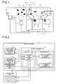
- FIG. 1 is an explanatory diagram illustrating a part of a robot system 1 according to a first embodiment.
- the robot system 1 is a system that transfers articles W sequentially conveyed on a conveyance path 2 to a predetermined placement table (hereinafter referred to as a "place 30") arranged beside the conveyance path 2.
- a predetermined placement table hereinafter referred to as a "place 30"
- the conveyance path 2 is a conveyor device such as a belt conveyor and a roller conveyor.
- the conveyor device includes a servo motor 2B that operates the conveyor device and an encoder 2C that detects a rotational position (that is, a conveyance position of the conveyor device) of the servo motor 2B.
- the servo motor 2B and the encoder 2C are connected to a control device (a robot controller 5 in the present embodiment).
- the servo motor 2B operates according to an instruction of the robot controller 5. Thereby, the conveyance path 2 sequentially conveys a plurality of articles W from an upstream side to a downstream side in a conveyance direction indicated by void arrows in FIG. 1 .
- the encoder 2C outputs the rotational position of the servo motor 2B to the robot controller 5.
- the conveyance path 2 may convey the articles W at a constant conveyance speed set in advance.
- the conveyance path 2 is not limited to a conveyor, but may be a shooter or the like which is formed so that a conveyance surface forms a downslope from the upstream side to the downstream side and conveys the articles W from the upstream side to the downstream side.
- the robot system 1 includes a plurality of robots 3-1 and 3-2 that take out the article W from the conveyance path 2 and transfer the article W to the place 30. Although, in FIG. 1 , two robots 3-1 and 3-2 are illustrated, the robot system 1 includes n robots (n is a natural number) (see FIG. 2 ).
- the robots are referred to as a first robot 3-1, a second robot 3-2, ⁇ , and nth robot 3-n in an order from the robot of which takeout position of the article W on the conveyance path 2 is the most upstream.
- each robot is simply referred to as a robot.
- the robot system 1 further includes an information acquisition unit 4 that acquires information related to the articles W conveyed on the conveyance path 2 and the robot controller 5 that controls operations of the conveyance path 2 and the first robot 3-1 to the nth robot 3-n.
- the information acquisition unit 4 is, for example, an image capturing device.
- the information acquisition unit 4 captures an image of the article W conveyed to an image capturing area 20 defined on the immediately upstream side of a first takeout area 2-1 on the conveyance path 2 from which the first robot 3-1 takes out the article W, and outputs image information of the captured image to the robot controller 5.
- the first robot 3-1 includes a single-arm serial link robot arm 3-1A and an end effector 3-1B provided at the tip of the robot arm 3-1A.
- the end effector 3-1B includes, for example, a sucker which adsorbs and holds an article by applying negative pressure by a vacuum pump and releases the article by releasing the negative pressure.
- the end effector 3-1B is not limited to a device that adsorbs and holds an article as long as the end effector 3-1B has a mechanism that can hold and convey an article.
- the end effector 3-1B is provided with a transfer detection unit 31 (see FIG. 2 ) that detects whether or not the article W is successfully transferred.
- the transfer detection unit 31 outputs a transfer result indicating whether or not the article W is successfully transferred to the robot controller 5.
- the first robot 3-1 takes out the article W from the first takeout area 2-1 of the conveyance path 2 according to control of the robot controller 5 and transfers the article W to a place 30 provided at a predetermined position.
- the second robot 3-2 to the nth robot 3-n have the same configuration as that of the first robot 3-1 and perform the same operation as that of the first robot 3-1.
- the second robot 3-2 takes out the article W from a second takeout area 2-2 on the immediately downstream side of the first takeout area 2-1 on the conveyance path 2 and transfers the article W to a place 30 provided at a predetermined position.
- the transfer detection units 31 of the second robot 3-2 to the nth robot 3-n output a transfer result indicating whether or not the article W is successfully transferred to the robot controller 5 in the same manner as the transfer detection units 31 of the first robot 3-1.
- FIG. 1 illustrates a case in which the first robot 3-1 and the second robot 3-2 are a serial link robot
- the first robot 3-1 to the nth robot 3-n may be a parallel link robot.
- the robot controller 5 is a control device that controls operations of the conveyance path 2 and the first robot 3-1 to the nth robot 3-n (see FIG. 2 ).
- the robot controller 5 detects two-dimensional positions of the articles W in the image capturing area 20 based on the image information inputted from the information acquisition unit 4.
- the robot controller 5 calculates the two-dimensional positions on the conveyance path 2 of the articles W conveyed to the first takeout area 2-1 on the basis of the detected two-dimensional positions of the articles W in the image capturing area 20 and the rotational position of the servo motor 2B inputted from the encoder 2C of the conveyance path 2. Then, the robot controller 5 provides the two-dimensional positions of the articles W conveyed to the first takeout area 2-1 to the first robot 3-1 as information related to the articles W to be transferred.
- the robot controller 5 provides information of articles W that are not transferred by a robot on the immediately upstream side to the second robot 3-2 to the nth robot 3-n (see FIG. 2 ) which transfer the articles W on the downstream side of the first robot 3-1 on the conveyance path 2.
- the robot controller 5 when a transfer result indicating failure of transfer is inputted to the robot controller 5 from the first robot 3-1, the robot controller 5 outputs the two-dimensional positions in the second takeout area 2-2 of the articles W, which the first robot 3-1 fails to transfer, to the second robot 3-2.
- the second robot 3-2 can take out and transfer the articles W, which the first robot 3-1 fails to transfer and which pass through the first takeout area 2-1, from the second takeout area 2-2 on the downstream side of the first takeout area 2-1.
- the robot system 1 even when any of a plurality of robots arranged along the conveyance path 2 fails to transfer the articles W, the articles W that are not transferred on the upstream side can be transferred by a robot located on the downstream side of the robot which fails to transfer the articles W. Therefore, according to the robot system 1, it is possible to prevent articles W that are not transferred from the conveyance path 2 by any robot from occurring.
- FIG. 2 is a block diagram illustrating the configuration of the robot system 1 according to the first embodiment.
- the robot system 1 includes n robots, which are the first robot 3-1 to the nth robot 3-n, the information acquisition unit 4, and the robot controller 5.
- each of the first robot 3-1 to the nth robot 3-n includes the transfer detection unit 31 that detects a transfer result of the articles W and outputs the transfer result of the articles W to the robot controller 5.
- the information acquisition unit 4 has already been described, so that the description thereof will be omitted here.
- the robot controller 5 includes a control unit 6 and a storage unit 7.
- the storage unit 7 stores first transfer target information 7-1 to nth transfer target information 7-n.
- the first transfer target information 7-1 is information related to the transfer targets of the first robot 3-1
- the nth transfer target information 7-n is information related to the transfer targets of the nth robot 3-n.
- the storage unit 7 stores transfer target information related to the transfer targets of each robot for each robot included in the robot system 1.
- a specific example of the information stored by the storage unit 7 will be described later with reference to FIGs. 3A and 3B .
- the control unit 6 includes an information providing unit 61 that provides information related to transfer target articles W to the first robot 3-1 to the nth robot 3-n. Although omitted here in FIG. 2 , the control unit 6 includes an instruction unit that instructs the first robot 3-1 to the nth robot 3-n to perform various operations in addition to the information providing unit 61.
- the information providing unit 61 updates the first transfer target information 7-1 to the nth transfer target information 7-n on the basis of the information inputted from the information acquisition unit 4, the rotational position of the servo motor 2B inputted from the encoder 2C of the conveyance path 2, and the transfer results of articles W inputted from each transfer detection unit 31.
- the information providing unit 61 provides information related to the transfer target articles W to the first robot 3-1 to the nth robot 3-n on the basis of the first transfer target information 7-1 to the nth transfer target information 7-n which are sequentially updated.
- the information providing unit 61 provides information related to the transfer target articles W to the first robot 3-1 to the nth robot 3-n on the basis of the first transfer target information 7-1 to the nth transfer target information 7-n which are sequentially updated.
- FIGs. 3A and 3B an example of the operation of the information providing unit 61 will be described with reference to FIGs. 3A and 3B .
- FIGs. 3A and 3B are explanatory diagrams illustrating an example of the information stored by the storage unit 7 according to the first embodiment.
- the three articles W are referred to as an article W1, an article W2, and an article W3 to distinguish these articles.
- the articles are simply referred to as an article W.
- the information providing unit 61 analyzes the image information and detects the two-dimensional positions of the article W1, the article W2, and the article W3 in the image capturing area 20.
- the information providing unit 61 sets an origin at the lower-left corner of the image capturing area 20 illustrated in FIG. 1 , sets an X axis from the origin in the conveyance direction of the articles W (direction indicated by void arrows in FIG. 1 ), and sets a Y axis from the origin in a direction vertically crossing the conveyance path 2.
- the information providing unit 61 calculates the X coordinate and the Y coordinate of the article W1, the article W2, and the article W3 on the XY coordinate plane set on the image capturing area 20 and stores the X coordinates and the Y coordinates in an area that stores the article positions in the first transfer target information 7-1.
- the information providing unit 61 updates the X coordinates of the articles W in the first transfer target information 7-1 based on the time when the images of the article W1, the article W2, and the article W3 are captured by the information acquisition unit 4 and the rotational position of the servo motor 2B inputted from the encoder 2C of the conveyance path 2. At this time, the information providing unit 61 updates the X coordinates of the articles W, for example, every time each robot has transferred the articles W.
- the X coordinates of the articles W may be updated at any timing, such as at predetermined processing periods (for example, several ms) set in advance.
- the X coordinate and the Y coordinate (hereinafter simply referred to as an "article position") indicating the current position on the conveyance path 2 of the article W1, the article W2, and the article W3 are sequentially updated to the current article position and stored.
- the information providing unit 61 Every time the information providing unit 61 updates the article positions of the article W1, the article W2, and the article W3, the information providing unit 61 provides the article positions of the article W1, the article W2, and the article W3 in the updated first transfer target information 7-1 to the first robot 3-1.
- the first robot 3-1 performs an operation to transfer the article W1, the article W2, and the article W3 from the conveyance path 2 to the place 30 based on the article positions provided from the information providing unit 61.
- the transfer detection unit 31 of the first robot 3-1 outputs transfer results indicating whether or not the article W1, the article W2, and the article W3 are successfully transferred to the information providing unit 61.
- the information providing unit 61 stores the transfer results inputted from the transfer detection unit 31 of the first robot 3-1 in an area that stores the transfer results in the first transfer target information 7-1.
- the information providing unit 61 stores information indicating the article position of the article W2 in an area that stores the article positions in the second transfer target information 7-2.
- the information providing unit 61 also sequentially updates the article position of the article W2 in the second transfer target information 7-2 to current article positions based on the rotational position of the servo motor 2B inputted from the encoder 2C of the conveyance path 2.
- the information providing unit 61 provides the article position of the article W2 to the second robot 3-2 based on the second transfer target information 7-2.
- the second robot 3-2 performs an operation to transfer the article W2 from the conveyance path 2 to the place 30 based on the article position of the article W2 provided from the information providing unit 61.
- the article W2 which the first robot 3-1 fails to transfer is transferred from the conveyance path 2 to the place 30 by the second robot 3-2, so that it is possible to prevent an article W that is not transferred by any robot from occurring in the robot system 1.
- the information providing unit 61 performs the same process as that performed when the first robot 3-1 fails to transfer an article W, so that the information providing unit 61 prevents an article W that is not transferred by any robot from occurring.
- the information providing unit 61 provides the article position of the article W which the robot fails to transfer to a robot that transfers articles W on the immediately downstream side of the robot that fails to transfer the article W on the immediately upstream side.
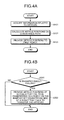
- FIGs. 4A and 4B are flowcharts illustrating processes performed by the information providing unit 61 according to the first embodiment.
- the information providing unit 61 Every time the image information of a captured image that is captured at a predetermined cycle by the information acquisition unit 4 is inputted into the information providing unit 61, the information providing unit 61 performs the process illustrated in FIG. 4A . Specifically, when the image information is inputted into the information providing unit 61 from the information acquisition unit 4, as illustrated in FIG. 4A , the information providing unit 61 acquires the image information as information related to the articles W (step S101).
- the information providing unit 61 calculates the article positions of the articles W on the surface of the conveyance path 2 from the image information acquired in step S101 and the rotational position of the servo motor 2B inputted from the encoder 2C of the conveyance path 2 (step S102). Then, the information providing unit 61 provides the calculated article positions to the first robot 3-1 (step S103) and ends the process.
- the information providing unit 61 performs the process illustrated in FIG. 4B . Specifically, when a transfer result of the articles W is inputted into the information providing unit 61 from any robot, as illustrated in FIG. 4B , the information providing unit 61 determines whether or not the inputted transfer result is a failure (step S201). The information providing unit 61 stores the determination result of the transfer result in the storage unit 7.
- step S201 When the transfer result is a failure (step S201, Yes), the information providing unit 61 provides the article positions of the articles W which a robot on the immediately upstream side fails to transfer to a robot that transfers the articles W on the immediately downstream side of the robot that fails to transfer the articles W (step S202). On the other hand, when the transfer result is a success (step S201, No), the information providing unit 61 ends the process.
- the robot system includes the information acquisition unit, a plurality of robots, and the information providing unit.
- the information acquisition unit acquires information related to the articles conveyed on the conveyance path.
- the plurality of robots transfers the articles from the conveyance path.
- the information providing unit provides information related to transfer target articles to a robot that transfers articles on the immediately downstream side of the acquisition position of the information on the conveyance path, and for a robot that transfers articles on the downstream side of the aforementioned robot, the information providing unit provides information related to articles that are not transferred by a robot on the immediately upstream side of the robot.
- information related to all the conveyed articles W is provided to the first robot 3-1 that transfers the articles W from immediately downstream side of the image capturing area 20 in the conveyance path 2
- information related to a part of the articles W may be provided.
- the information providing unit 61 may provide, to the first robot 3-1, the article positions of a part of all the articles W that are conveyed to the first takeout area 2-1 and may distribute and provide the article positions of the remaining articles W to the second robot 3-2 to the nth robot 3-n in advance.
- the information providing unit 61 provides the article positions of the articles W which the robot on the immediately upstream side fails to transfer to a robot that transfers articles W on the immediately downstream side of the robot that fails to transfer the articles W.
- whether or not the articles W are transferred by each robot is determined based on the transfer result outputted from the transfer detection unit 31 of each robot.
- the method of determining whether or not the articles W are transferred by each robot is not limited to this.
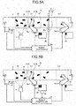
- FIG. 5A is a block diagram illustrating a configuration of a robot system 1a according to a modified example 1 of the first embodiment
- FIG. 5B is a block diagram illustrating a configuration of a robot system 1b according to a modified example 2 of the first embodiment.
- the robot systems 1a and 1b which include two robots will be described as an example.
- the number of robots included in each of the robot systems 1a and 1b may be three or more.
- the robot system 1a includes a detection unit 8 that detects articles W passing through an area between the first takeout area 2-1 and the second takeout area 2-2 and detects the articles W that are not transferred by a first robot 3a-1 by the detection unit 8.
- the first robot 3a-1 and a second robot 3a-2 in the robot system 1a have the same configuration as that of the first robot 3-1 and the second robot 3-2 illustrated in FIG. 1 except that the first robot 3a-1 and the second robot 3a-2 do not include the transfer detection unit 31 (see FIG. 2 ).
- the detection unit 8 is, for example, an infrared sensor which includes a light emitting unit 81 and a light receiving unit 82 provided at positions opposite to each other with the conveyance path 2 in between and detects passing of an article W by determining whether or not infrared light 83 emitted from the light emitting unit 81 is received by the light receiving unit 82.
- the detection unit 8 detects passing of the article W between the first takeout area 2-1 and the second takeout area 2-2.
- the detection unit 8 outputs the detection result to a robot controller 5a.
- the robot controller 5a calculates the article positions on the conveyance path 2 based on the image information inputted from the information acquisition unit 4 and the rotational position of the servo motor 2B inputted from the encoder 2C of the conveyance path 2. Then, the robot controller 5a provides the calculated article positions to the first robot 3a-1 as information related to the transfer target articles W.
- the robot controller 5a provides the article position on the conveyance path 2 of the article W that has passed through the area to the second robot 3a-2.
- the article W that is not transferred from the first takeout area 2-1 by the first robot 3a-1 can be transferred from the second takeout area 2-2 to the place 30 by the second robot 3a-2.
- the robot system 1a it is possible to prevent an article W that is not transferred by any robot from occurring.
- the detection unit 8 in the modified example 1 is not limited to an infrared sensor.
- the detection unit 8 may be an image capturing device that captures an image of an article W conveyed between the first takeout area 2-1 and the second takeout area 2-2.
- the robot controller 5a detects the current position on the conveyance path 2 of an article W conveyed between the first takeout area 2-1 and the second takeout area 2-2 based on an captured image that is captured by the detection unit 8 and the rotational position of the servo motor 2B inputted from the encoder 2C of the conveyance path 2, and provides the detected current position to the second robot 3a-2.
- the detection unit 8 that detects an article W passing through an area between the takeout areas on the conveyance path 2 from which each robot takes out articles W is provided for each area.
- the robot controller 5a When any of the detection units 8 detects passing of an article W, the robot controller 5a provides the article position of the article W of which passing is detected to a robot that transfers articles W on the immediately downstream side of the takeout area where the passing of the article W is detected. Thereby, in the robot system 1a, it is possible to prevent an article W that is not transferred by any robot from occurring without providing the transfer detection unit 31 (see FIG. 2 ) to each robot.
- the robot system 1b includes a detection unit 32 that detects the number of articles W transferred to each place 30.
- the detection unit 32 for example, it is possible to use a weight sensor that detects the number of articles W based on a total weight of the articles W transferred to the place 30 or pressure sensors that are provided at each placement position of the article W in the place 30 and detect placement of the articles W.
- the detection unit 32 outputs the detected number of the articles W to the controller 5b.
- the first robot 3a-1 and the second robot 3a-2 in the robot system 1b are robots in which the transfer detection unit 31 (see FIG. 2 ) is not provided in the same manner as in the modified example 1.
- the robot controller 5b calculates the article positions on the conveyance path 2 based on the image information inputted from the information acquisition unit 4 and the rotational position of the servo motor 2B inputted from the encoder 2C of the conveyance path 2. Then, the robot controller 5b provides the calculated article positions to the first robot 3a-1 as information related to the transfer target articles W.
- the robot controller 5b determines the articles W that are not transferred by the first robot 3a-1 based on the article positions provided to the first robot 3a-1 and the number of articles W inputted from the detection unit 32.
- the robot controller 5b estimates the articles W that are supposed to be transferred to the place 30 by the first robot 3a-1 and the number of articles W transferred to the place 30 based on the article positions.
- the robot controller 5b determines that the articles W that are supposed to be transferred are not transferred by the first robot 3a-1. Then, the robot controller 5b provides the article positions of articles W that are determined not to be transferred by the first robot 3a-1 to the second robot 3a-2.
- the articles W that are not transferred from the first takeout area 2-1 by the first robot 3a-1 can be transferred from the second takeout area 2-2 to the place 30 by the second robot 3a-2.
- the robot system 1b it is possible to prevent articles W that are not transferred by any robot from occurring.
- the detection unit 32 is provided to each place 30 that is provided for each robot.
- the robot controller 5b determines that the articles W that are supposed to be transferred to the place 30 are not transferred, the robot controller 5b provides the article positions of the articles W that are not transferred to the place 30 to a robot that transfers articles W on the immediately downstream side of the robot that does not transfer the articles W that are supposed to be transferred. Thereby, in the robot system 1b, it is possible to prevent articles W that are not transferred by any robot from occurring without providing the transfer detection unit 31 (see FIG. 2 ) to each robot.
- FIG. 6 is a block diagram illustrating a configuration of a robot system 1c according to the second embodiment
- FIG. 7 is an explanatory diagram illustrating an example of information stored by a robot controller 5c according to the second embodiment.
- the same components as those of the robot system 1 illustrated in FIGs. 1 and 2 or the robot system 1a illustrated in FIG. 5A are denoted by the same reference numerals as those in FIGs. 1 and 2 or FIG. 5A and the description thereof will be omitted.
- the robot system 1c including two robots will be described as an example.
- the number of robots included in each robot system 1c may be three or more.
- the robot system 1c illustrated in FIG. 6 is different from the robot systems 1, 1a, and 1b according to the first embodiment, which determine the articles W that are not transferred by a robot after the transfer is tried, in that the robot system 1c determines the articles W that are not transferred by a robot before the transfer is tried.
- the robot controller 5c determines in advance an article W2 that may not be transferred by the first robot 3a-1 based on the image information captured by the information acquisition unit 4.
- the article W1 and the article W2 may be aligned in a direction perpendicular to the conveyance direction (direction indicated by void arrows in FIG. 6 ).
- the article W1 and the article W2 pass through the first takeout area 2-1 at substantially the same time, so that either one may not be transferred by the first robot 3a-1. Therefore, before the article W1 and the article W2 are transferred to the first takeout area 2-1, the robot controller 5c determines in advance that either one of the article W1 and the article W2 (here, the article W2) is not transferred by the first robot 3a-1.
- the robot controller 5c stores the article positions of the article W1, the article W3, and the article W4 into an area in which the article positions are stored in the first transfer target information 7-1 in the storage unit 7.
- the robot controller 5c stores the article position of the article W2 into an area in which the article positions are stored in the second transfer target information 7-2.
- the article positions in the first transfer target information 7-1 or the second transfer target information 7-2 are sequentially updated to the current article positions by the robot controller 5c based on the rotational position of the servo motor 2B inputted from the encoder 2C of the conveyance path 2.
- the robot controller 5c provides in advance the article positions of the article W1, the article W3, and the article W4 in the first transfer target information 7-1 to the first robot 3a-1 and provides in advance the article position of the article W2 in the second transfer target information 7-2 to the second robot 3a-2.
- the article W2 can be transferred to the place 30 from the second takeout area 2-2 by the second robot 3a-2 which is provided with the article position of the article W2 in advance.
- the robot system 1c when the conveyance speed of the articles W conveyed by the conveyance path 2 is increased, it is possible to improve transfer efficiency of the articles W while preventing an article W that is not transferred by any robot from occurring.
- the robot controller 5c When the robot system 1c includes three or more robots, the robot controller 5c also distributes and provides the article positions of articles W that are highly probable not to be transferred by the first robot 3a-1 to a plurality of robots other than the second robot 3a-2.
- the robot system according to the second embodiment can prevent articles that are not transferred by any robot from occurring even when the conveyance speed of the articles conveyed by the conveyance path is increased, so that it is possible to improve the transfer efficiency of the articles.
- modified example 1, and modified example 2 may be added to the robot system 1c.
- the function to determine the articles W that are not transferred by each robot after the transfer is tried and provide information related to the articles W that are not transferred by a robot on the immediately upstream side to a robot on the immediately downstream side may be added to the robot system 1c. Thereby, it is possible to more reliably prevent articles W that are not transferred by any robot from occurring.
- FIG. 8 is a block diagram illustrating a configuration of the robot system 1d according to the third embodiment.
- the same components as those of the robot system 1 illustrated in FIG. 2 are denoted by the same reference numerals as those in FIG. 2 and the description thereof will be omitted.
- the robot system 1d illustrated in FIG. 8 includes n robot controllers (here, a first robot controller 5-1 to an nth robot controller 5-n), each of which is connected to each of the first robot 3-1 to the nth robot 3-n, respectively.
- the first robot controller 5-1 to the nth robot controller 5-n function as instruction units that issue various operation instructions to the first robot 3-1 to the nth robot 3-n, respectively.
- the robot system 1d includes an integrated controller 50 connected to the first robot controller 5-1 to the nth robot controller 5-n and the information acquisition unit 4.
- the integrated controller 50 has the same function as that of the information providing unit 61 illustrated in FIG. 2 in the robot system 1d.
- the integrated controller 50 calculates the article positions based on the image information inputted from the information acquisition unit 4 and the rotational position of the servo motor 2B inputted from the encoder 2C of the conveyance path 2, and distributes and provides the calculated article positions to the first robot 3-1 or the first robot 3-1 to the nth robot 3-n.
- the integrated controller 50 determines whether or not any of the first robot 3-1 to the nth robot 3-n fails to transfer the articles W on the basis of the transfer results acquired from the transfer detection units 31 through the first robot controller 5-1 to the nth robot controller 5-n.
- the integrated controller 50 provides the article positions of the articles W which the robot on the immediately upstream side fails to transfer to a robot that transfers articles W on the immediately downstream side of the robot that fails to transfer the articles W. Thereby, in the robot system 1d, it is possible to prevent articles W that are not transferred by any robot from occurring.
- the robot system 1d it is possible to use an inexpensive controller having a processing capacity lower than that of the robot controller 5 illustrated in FIG. 2 as the first robot controller 5-1 to the nth robot controller 5-n and the integrated controller 50.
- the robot system 1d it is possible to add a robot by only adding the robot and a robot controller that issues operation instructions to the robot without largely changing the control content of the integrated controller 50. Therefore, according to the robot system 1d, it is possible to easily add robots and further improve transfer efficiency of the articles W.
- robots can be easily added, so that it is possible to realize a robot system that can prevent articles that are not transferred by any robot from occurring at lower cost.
- a robot controller may be provided to each of the first robot 3a-1 and the second robot 3a-2 and the integrated controller 50 may be provided as a higher-level device of the robot controllers.
- the robot controller or the integrated controller may update the article positions on the conveyance path on the basis of the conveyance speed of the articles conveyed by the conveyance path.
Landscapes
- Engineering & Computer Science (AREA)
- Robotics (AREA)
- Mechanical Engineering (AREA)
- General Engineering & Computer Science (AREA)
- Manufacturing & Machinery (AREA)
- Quality & Reliability (AREA)
- Physics & Mathematics (AREA)
- General Physics & Mathematics (AREA)
- Automation & Control Theory (AREA)
- Manipulator (AREA)
- Specific Conveyance Elements (AREA)
- Control Of Position, Course, Altitude, Or Attitude Of Moving Bodies (AREA)
Abstract
Description
- Embodiments disclosed herein relate to a robot system and an article transfer method.
- Conventionally, there is a technique in which an article conveyed on a conveyance path such as a conveyor is taken out from the conveyance path and transferred to another position by a plurality of robots.
- For example,
Patent Literature 1 discloses a technique in which a first robot and a second robot are arranged along a conveyance path, and the first robot transfers an article on an upstream side of the conveyance path and the second robot conveys an article on a downstream side of the conveyance path. Further,Patent Literature 1 discloses a technique for distributing articles in advance on the conveyance path to each robot as transfer targets. - Patent Literature 1:
JP 3834088 B1 - However, the techniques described in
Patent Literature 1 have a problem that an article that is not transferred by any robot occurs. - Specifically, if an article that is distributed to the first robot is not transferred by the first robot for some reason, the article is not transferred by the second robot because the article is not distributed to the second robot in advance. As a result, in this case, an article that is not transferred by any robot occurs.
- An aspect of embodiments is made in view of the above circumstances and an objective of the aspect is to provide a robot system and an article transfer method that can prevent an article that is not transferred by any robot from occurring.
- A robot system according to an aspect of embodiments includes an information acquisition unit, a plurality of robots, and an information providing unit. The information acquisition unit acquires information related to articles conveyed on a conveyance path. The plurality of robots transfers the articles from the conveyance path. The information providing unit provides information related to transfer target articles to a robot that transfers articles on the immediately downstream side of an acquisition position of the information on the conveyance path, and for a robot that transfers articles on the downstream side of the aforementioned robot, the information providing unit provides information related to articles that are not transferred by a robot on the immediately upstream side of the robot.
- According to an aspect of the embodiments, it is possible to prevent an article that is not transferred by any robot from occurring.
-
-
FIG. 1 is an explanatory diagram illustrating a part of a robot system according to a first embodiment. -
FIG. 2 is a block diagram illustrating a configuration of the robot system according to the first embodiment. -
FIG. 3A is an explanatory diagram illustrating an example of information stored by a storage unit according to the first embodiment. -
FIG. 3B is an explanatory diagram illustrating an example of information stored by the storage unit according to the first embodiment. -
FIG. 4A is a flowchart illustrating a process performed by an information providing unit according to the first embodiment. -
FIG. 4B is a flowchart illustrating a process performed by the information providing unit according to the first embodiment. -
FIG. 5A is a block diagram illustrating a configuration of a robot system according to a modified example 1 of the first embodiment. -
FIG. 5B is a block diagram illustrating a configuration of a robot system according to a modified example 2 of the first embodiment. -
FIG. 6 is a block diagram illustrating a configuration of a robot system according to a second embodiment. -
FIG. 7 is an explanatory diagram illustrating an example of information stored by a robot controller according to the second embodiment. -
FIG. 8 is a block diagram illustrating a configuration of a robot system according to a third embodiment. Description of Embodiments - Hereinafter, embodiments of the robot system and the article transfer method disclosed by the present application will be described in detail with reference to the accompanying drawings. The present invention is not limited by the embodiments described below.
-
FIG. 1 is an explanatory diagram illustrating a part of arobot system 1 according to a first embodiment. As illustrated inFIG. 1 , therobot system 1 is a system that transfers articles W sequentially conveyed on aconveyance path 2 to a predetermined placement table (hereinafter referred to as a "place 30") arranged beside theconveyance path 2. - Here, the
conveyance path 2 according to the present embodiment is a conveyor device such as a belt conveyor and a roller conveyor. The conveyor device includes aservo motor 2B that operates the conveyor device and anencoder 2C that detects a rotational position (that is, a conveyance position of the conveyor device) of theservo motor 2B. Theservo motor 2B and theencoder 2C are connected to a control device (arobot controller 5 in the present embodiment). - The servo
motor 2B operates according to an instruction of therobot controller 5. Thereby, theconveyance path 2 sequentially conveys a plurality of articles W from an upstream side to a downstream side in a conveyance direction indicated by void arrows inFIG. 1 . Theencoder 2C outputs the rotational position of theservo motor 2B to therobot controller 5. - The
conveyance path 2 may convey the articles W at a constant conveyance speed set in advance. Theconveyance path 2 is not limited to a conveyor, but may be a shooter or the like which is formed so that a conveyance surface forms a downslope from the upstream side to the downstream side and conveys the articles W from the upstream side to the downstream side. - The
robot system 1 includes a plurality of robots 3-1 and 3-2 that take out the article W from theconveyance path 2 and transfer the article W to theplace 30. Although, inFIG. 1 , two robots 3-1 and 3-2 are illustrated, therobot system 1 includes n robots (n is a natural number) (seeFIG. 2 ). - In the description below, when a specific robot is indicated from among the n robots included in the
robot system 1, the robots are referred to as a first robot 3-1, a second robot 3-2, ···, and nth robot 3-n in an order from the robot of which takeout position of the article W on theconveyance path 2 is the most upstream. When a specific robot is not indicated, each robot is simply referred to as a robot. - The
robot system 1 further includes aninformation acquisition unit 4 that acquires information related to the articles W conveyed on theconveyance path 2 and therobot controller 5 that controls operations of theconveyance path 2 and the first robot 3-1 to the nth robot 3-n. - Here, the
information acquisition unit 4 is, for example, an image capturing device. Theinformation acquisition unit 4 captures an image of the article W conveyed to animage capturing area 20 defined on the immediately upstream side of a first takeout area 2-1 on theconveyance path 2 from which the first robot 3-1 takes out the article W, and outputs image information of the captured image to therobot controller 5. - The first robot 3-1 includes a single-arm serial link robot arm 3-1A and an end effector 3-1B provided at the tip of the robot arm 3-1A. Here, the end effector 3-1B includes, for example, a sucker which adsorbs and holds an article by applying negative pressure by a vacuum pump and releases the article by releasing the negative pressure. The end effector 3-1B is not limited to a device that adsorbs and holds an article as long as the end effector 3-1B has a mechanism that can hold and convey an article.
- The end effector 3-1B is provided with a transfer detection unit 31 (see
FIG. 2 ) that detects whether or not the article W is successfully transferred. Thetransfer detection unit 31 outputs a transfer result indicating whether or not the article W is successfully transferred to therobot controller 5. - The first robot 3-1 takes out the article W from the first takeout area 2-1 of the
conveyance path 2 according to control of therobot controller 5 and transfers the article W to aplace 30 provided at a predetermined position. - The second robot 3-2 to the nth robot 3-n (see
FIG. 2 ) have the same configuration as that of the first robot 3-1 and perform the same operation as that of the first robot 3-1. For example, the second robot 3-2 takes out the article W from a second takeout area 2-2 on the immediately downstream side of the first takeout area 2-1 on theconveyance path 2 and transfers the article W to aplace 30 provided at a predetermined position. - The
transfer detection units 31 of the second robot 3-2 to the nth robot 3-n output a transfer result indicating whether or not the article W is successfully transferred to therobot controller 5 in the same manner as thetransfer detection units 31 of the first robot 3-1. - Although
FIG. 1 illustrates a case in which the first robot 3-1 and the second robot 3-2 are a serial link robot, the first robot 3-1 to the nth robot 3-n may be a parallel link robot. - The
robot controller 5 is a control device that controls operations of theconveyance path 2 and the first robot 3-1 to the nth robot 3-n (seeFIG. 2 ). Therobot controller 5 detects two-dimensional positions of the articles W in theimage capturing area 20 based on the image information inputted from theinformation acquisition unit 4. - Further, the
robot controller 5 calculates the two-dimensional positions on theconveyance path 2 of the articles W conveyed to the first takeout area 2-1 on the basis of the detected two-dimensional positions of the articles W in theimage capturing area 20 and the rotational position of theservo motor 2B inputted from theencoder 2C of theconveyance path 2. Then, therobot controller 5 provides the two-dimensional positions of the articles W conveyed to the first takeout area 2-1 to the first robot 3-1 as information related to the articles W to be transferred. - The
robot controller 5 provides information of articles W that are not transferred by a robot on the immediately upstream side to the second robot 3-2 to the nth robot 3-n (seeFIG. 2 ) which transfer the articles W on the downstream side of the first robot 3-1 on theconveyance path 2. - For example, when a transfer result indicating failure of transfer is inputted to the
robot controller 5 from the first robot 3-1, therobot controller 5 outputs the two-dimensional positions in the second takeout area 2-2 of the articles W, which the first robot 3-1 fails to transfer, to the second robot 3-2. - Thereby, in the
robot system 1, the second robot 3-2 can take out and transfer the articles W, which the first robot 3-1 fails to transfer and which pass through the first takeout area 2-1, from the second takeout area 2-2 on the downstream side of the first takeout area 2-1. - In other words, in the
robot system 1, even when any of a plurality of robots arranged along theconveyance path 2 fails to transfer the articles W, the articles W that are not transferred on the upstream side can be transferred by a robot located on the downstream side of the robot which fails to transfer the articles W. Therefore, according to therobot system 1, it is possible to prevent articles W that are not transferred from theconveyance path 2 by any robot from occurring. - Next, a configuration of the
robot system 1 will be described with reference toFIG. 2. FIG. 2 is a block diagram illustrating the configuration of therobot system 1 according to the first embodiment. As illustrated inFIG. 2 , therobot system 1 includes n robots, which are the first robot 3-1 to the nth robot 3-n, theinformation acquisition unit 4, and therobot controller 5. - As described above, each of the first robot 3-1 to the nth robot 3-n includes the
transfer detection unit 31 that detects a transfer result of the articles W and outputs the transfer result of the articles W to therobot controller 5. Theinformation acquisition unit 4 has already been described, so that the description thereof will be omitted here. - The
robot controller 5 includes acontrol unit 6 and astorage unit 7. Thestorage unit 7 stores first transfer target information 7-1 to nth transfer target information 7-n. Here, the first transfer target information 7-1 is information related to the transfer targets of the first robot 3-1 and the nth transfer target information 7-n is information related to the transfer targets of the nth robot 3-n. - In other words, the
storage unit 7 stores transfer target information related to the transfer targets of each robot for each robot included in therobot system 1. A specific example of the information stored by thestorage unit 7 will be described later with reference toFIGs. 3A and 3B . - The
control unit 6 includes aninformation providing unit 61 that provides information related to transfer target articles W to the first robot 3-1 to the nth robot 3-n. Although omitted here inFIG. 2 , thecontrol unit 6 includes an instruction unit that instructs the first robot 3-1 to the nth robot 3-n to perform various operations in addition to theinformation providing unit 61. - The
information providing unit 61 updates the first transfer target information 7-1 to the nth transfer target information 7-n on the basis of the information inputted from theinformation acquisition unit 4, the rotational position of theservo motor 2B inputted from theencoder 2C of theconveyance path 2, and the transfer results of articles W inputted from eachtransfer detection unit 31. - Then, the
information providing unit 61 provides information related to the transfer target articles W to the first robot 3-1 to the nth robot 3-n on the basis of the first transfer target information 7-1 to the nth transfer target information 7-n which are sequentially updated. Hereinafter, an example of the operation of theinformation providing unit 61 will be described with reference toFIGs. 3A and 3B . -
FIGs. 3A and 3B are explanatory diagrams illustrating an example of the information stored by thestorage unit 7 according to the first embodiment. Here, as an example, a case will be described in which there are three articles W in theimage capturing area 20. In the description below, the three articles W are referred to as an article W1, an article W2, and an article W3 to distinguish these articles. When the articles are not distinguished, the articles are simply referred to as an article W. - When image information of a captured image of the article W1, the article W2, and the article W3 is inputted into the
information providing unit 61 from theinformation acquisition unit 4, theinformation providing unit 61 analyzes the image information and detects the two-dimensional positions of the article W1, the article W2, and the article W3 in theimage capturing area 20. - For example, the
information providing unit 61 sets an origin at the lower-left corner of theimage capturing area 20 illustrated inFIG. 1 , sets an X axis from the origin in the conveyance direction of the articles W (direction indicated by void arrows inFIG. 1 ), and sets a Y axis from the origin in a direction vertically crossing theconveyance path 2. - Then, as illustrated in
FIG. 3A , theinformation providing unit 61 calculates the X coordinate and the Y coordinate of the article W1, the article W2, and the article W3 on the XY coordinate plane set on theimage capturing area 20 and stores the X coordinates and the Y coordinates in an area that stores the article positions in the first transfer target information 7-1. - Further, the
information providing unit 61 updates the X coordinates of the articles W in the first transfer target information 7-1 based on the time when the images of the article W1, the article W2, and the article W3 are captured by theinformation acquisition unit 4 and the rotational position of theservo motor 2B inputted from theencoder 2C of theconveyance path 2. At this time, theinformation providing unit 61 updates the X coordinates of the articles W, for example, every time each robot has transferred the articles W. The X coordinates of the articles W may be updated at any timing, such as at predetermined processing periods (for example, several ms) set in advance. - Thereby, in the area that stores the article positions in the first transfer target information 7-1, the X coordinate and the Y coordinate (hereinafter simply referred to as an "article position") indicating the current position on the
conveyance path 2 of the article W1, the article W2, and the article W3 are sequentially updated to the current article position and stored. - Every time the
information providing unit 61 updates the article positions of the article W1, the article W2, and the article W3, theinformation providing unit 61 provides the article positions of the article W1, the article W2, and the article W3 in the updated first transfer target information 7-1 to the first robot 3-1. The first robot 3-1 performs an operation to transfer the article W1, the article W2, and the article W3 from theconveyance path 2 to theplace 30 based on the article positions provided from theinformation providing unit 61. - Thereafter, the
transfer detection unit 31 of the first robot 3-1 outputs transfer results indicating whether or not the article W1, the article W2, and the article W3 are successfully transferred to theinformation providing unit 61. As illustrated inFIG. 3B , theinformation providing unit 61 stores the transfer results inputted from thetransfer detection unit 31 of the first robot 3-1 in an area that stores the transfer results in the first transfer target information 7-1. - Here, as illustrated in
FIG. 3B , when the first robot 3-1 successfully transfers the article W1 and the article W3 and fails to transfer the article W2, theinformation providing unit 61 stores information indicating the article position of the article W2 in an area that stores the article positions in the second transfer target information 7-2. Theinformation providing unit 61 also sequentially updates the article position of the article W2 in the second transfer target information 7-2 to current article positions based on the rotational position of theservo motor 2B inputted from theencoder 2C of theconveyance path 2. - Then, the
information providing unit 61 provides the article position of the article W2 to the second robot 3-2 based on the second transfer target information 7-2. The second robot 3-2 performs an operation to transfer the article W2 from theconveyance path 2 to theplace 30 based on the article position of the article W2 provided from theinformation providing unit 61. - Thereby, the article W2 which the first robot 3-1 fails to transfer is transferred from the
conveyance path 2 to theplace 30 by the second robot 3-2, so that it is possible to prevent an article W that is not transferred by any robot from occurring in therobot system 1. - Further, when the second robot 3-2 to the nth robot 3-n fail to transfer an article W, the
information providing unit 61 performs the same process as that performed when the first robot 3-1 fails to transfer an article W, so that theinformation providing unit 61 prevents an article W that is not transferred by any robot from occurring. - In other words, when a certain robot fails to transfer an article W, the
information providing unit 61 provides the article position of the article W which the robot fails to transfer to a robot that transfers articles W on the immediately downstream side of the robot that fails to transfer the article W on the immediately upstream side. Thereby, in therobot system 1, it is possible to prevent an article W that is not transferred by any robot from occurring. - Next, a process performed by the
information providing unit 61 will be described with reference toFIGs. 4A and 4B. FIGs. 4A and 4B are flowcharts illustrating processes performed by theinformation providing unit 61 according to the first embodiment. - Every time the image information of a captured image that is captured at a predetermined cycle by the
information acquisition unit 4 is inputted into theinformation providing unit 61, theinformation providing unit 61 performs the process illustrated inFIG. 4A . Specifically, when the image information is inputted into theinformation providing unit 61 from theinformation acquisition unit 4, as illustrated inFIG. 4A , theinformation providing unit 61 acquires the image information as information related to the articles W (step S101). - Subsequently, the
information providing unit 61 calculates the article positions of the articles W on the surface of theconveyance path 2 from the image information acquired in step S101 and the rotational position of theservo motor 2B inputted from theencoder 2C of the conveyance path 2 (step S102). Then, theinformation providing unit 61 provides the calculated article positions to the first robot 3-1 (step S103) and ends the process. - Every time a transfer result of the articles W is inputted into the
information providing unit 61 from any robot of the first robot 3-1 to the nth robot 3-n, theinformation providing unit 61 performs the process illustrated inFIG. 4B . Specifically, when a transfer result of the articles W is inputted into theinformation providing unit 61 from any robot, as illustrated inFIG. 4B , theinformation providing unit 61 determines whether or not the inputted transfer result is a failure (step S201). Theinformation providing unit 61 stores the determination result of the transfer result in thestorage unit 7. - When the transfer result is a failure (step S201, Yes), the
information providing unit 61 provides the article positions of the articles W which a robot on the immediately upstream side fails to transfer to a robot that transfers the articles W on the immediately downstream side of the robot that fails to transfer the articles W (step S202). On the other hand, when the transfer result is a success (step S201, No), theinformation providing unit 61 ends the process. - As described above, the robot system according to the first embodiment includes the information acquisition unit, a plurality of robots, and the information providing unit. The information acquisition unit acquires information related to the articles conveyed on the conveyance path. The plurality of robots transfers the articles from the conveyance path.
- The information providing unit provides information related to transfer target articles to a robot that transfers articles on the immediately downstream side of the acquisition position of the information on the conveyance path, and for a robot that transfers articles on the downstream side of the aforementioned robot, the information providing unit provides information related to articles that are not transferred by a robot on the immediately upstream side of the robot. Thereby, according to the first embodiment, it is possible to provide a robot system and an article transfer method which can prevent articles that are not transferred by any robot from occurring.
- Although a case has been described in which information related to all the conveyed articles W is provided to the first robot 3-1 that transfers the articles W from immediately downstream side of the
image capturing area 20 in theconveyance path 2, information related to a part of the articles W may be provided. - For example, the
information providing unit 61 may provide, to the first robot 3-1, the article positions of a part of all the articles W that are conveyed to the first takeout area 2-1 and may distribute and provide the article positions of the remaining articles W to the second robot 3-2 to the nth robot 3-n in advance. - When any of the first robot 3-1 to the nth robot 3-n to which the article positions are provided fails to transfer the articles W, the
information providing unit 61 provides the article positions of the articles W which the robot on the immediately upstream side fails to transfer to a robot that transfers articles W on the immediately downstream side of the robot that fails to transfer the articles W. - By distributing the article positions of the transfer target articles W to a plurality of robots in advance in this way, it is possible to reduce the number of articles W which each robot fails to transfer. Thereby, it is possible to reduce the amount of processing performed by the
information providing unit 61 when a robot fails to transfer the articles W. - In the present embodiment, whether or not the articles W are transferred by each robot is determined based on the transfer result outputted from the
transfer detection unit 31 of each robot. However, the method of determining whether or not the articles W are transferred by each robot is not limited to this. - Here, modified examples of the method of determining whether or not the articles W are transferred by each robot will be described with reference to
FIGs. 5A and 5B. FIG. 5A is a block diagram illustrating a configuration of arobot system 1a according to a modified example 1 of the first embodiment, andFIG. 5B is a block diagram illustrating a configuration of arobot system 1b according to a modified example 2 of the first embodiment. - Here, among components of the
robot systems robot system 1 illustrated inFIG. 1 are denoted by the same reference numerals as those inFIG. 1 and the description thereof will be omitted. - In the description below, the
robot systems robot systems - First, the
robot system 1a according to the modified example 1 will be described with reference toFIG. 5A . As illustrated inFIG. 5A , therobot system 1a includes adetection unit 8 that detects articles W passing through an area between the first takeout area 2-1 and the second takeout area 2-2 and detects the articles W that are not transferred by afirst robot 3a-1 by thedetection unit 8. - The
first robot 3a-1 and asecond robot 3a-2 in therobot system 1a have the same configuration as that of the first robot 3-1 and the second robot 3-2 illustrated inFIG. 1 except that thefirst robot 3a-1 and thesecond robot 3a-2 do not include the transfer detection unit 31 (seeFIG. 2 ). - Here, the
detection unit 8 is, for example, an infrared sensor which includes alight emitting unit 81 and alight receiving unit 82 provided at positions opposite to each other with theconveyance path 2 in between and detects passing of an article W by determining whether or not infrared light 83 emitted from thelight emitting unit 81 is received by thelight receiving unit 82. - When the
infrared light 83 is blocked by an article W conveyed on theconveyance path 2 and theinfrared light 83 is not received by thelight receiving unit 82, thedetection unit 8 detects passing of the article W between the first takeout area 2-1 and the second takeout area 2-2. When thedetection unit 8 detects passing of the article W, thedetection unit 8 outputs the detection result to arobot controller 5a. - The
robot controller 5a calculates the article positions on theconveyance path 2 based on the image information inputted from theinformation acquisition unit 4 and the rotational position of theservo motor 2B inputted from theencoder 2C of theconveyance path 2. Then, therobot controller 5a provides the calculated article positions to thefirst robot 3a-1 as information related to the transfer target articles W. - Thereafter, if a detection result indicating that an article W passes through an area between the first takeout area 2-1 and the second takeout area 2-2 is inputted into the
robot controller 5a from thedetection unit 8, therobot controller 5a provides the article position on theconveyance path 2 of the article W that has passed through the area to thesecond robot 3a-2. - Thereby, in the
robot system 1a, the article W that is not transferred from the first takeout area 2-1 by thefirst robot 3a-1 can be transferred from the second takeout area 2-2 to theplace 30 by thesecond robot 3a-2. As a result, according to therobot system 1a, it is possible to prevent an article W that is not transferred by any robot from occurring. - The
detection unit 8 in the modified example 1 is not limited to an infrared sensor. For example, thedetection unit 8 may be an image capturing device that captures an image of an article W conveyed between the first takeout area 2-1 and the second takeout area 2-2. - When an image capturing device is used as the
detection unit 8, therobot controller 5a detects the current position on theconveyance path 2 of an article W conveyed between the first takeout area 2-1 and the second takeout area 2-2 based on an captured image that is captured by thedetection unit 8 and the rotational position of theservo motor 2B inputted from theencoder 2C of theconveyance path 2, and provides the detected current position to thesecond robot 3a-2. - According to this configuration, for example, even when a position of an article W which the
first robot 3a-1 fails to transfer is largely shifted from a holding position of the article W held by thefirst robot 3a-1, it is possible to provide an accurate article position of the article W on theconveyance path 2 to thesecond robot 3a-2. - When the
robot system 1a includes three or more robots, thedetection unit 8 that detects an article W passing through an area between the takeout areas on theconveyance path 2 from which each robot takes out articles W is provided for each area. - When any of the
detection units 8 detects passing of an article W, therobot controller 5a provides the article position of the article W of which passing is detected to a robot that transfers articles W on the immediately downstream side of the takeout area where the passing of the article W is detected. Thereby, in therobot system 1a, it is possible to prevent an article W that is not transferred by any robot from occurring without providing the transfer detection unit 31 (seeFIG. 2 ) to each robot. - Further, according to this configuration, it is possible to obtain the same effect as that of the
robot system 1a by, for example, only providing thedetection unit 8 to an existing robot system where articles are transferred from a conveyance path by robots that do not include the transfer detection unit 31 (seeFIG. 2 ) and changing control content of a robot controller. - Next, the
robot system 1b according to a modified example 2 will be described with reference toFIG. 5B . As illustrated inFIG. 5B , therobot system 1b includes adetection unit 32 that detects the number of articles W transferred to eachplace 30. - As the
detection unit 32, for example, it is possible to use a weight sensor that detects the number of articles W based on a total weight of the articles W transferred to theplace 30 or pressure sensors that are provided at each placement position of the article W in theplace 30 and detect placement of the articles W. Thedetection unit 32 outputs the detected number of the articles W to thecontroller 5b. - The
first robot 3a-1 and thesecond robot 3a-2 in therobot system 1b are robots in which the transfer detection unit 31 (seeFIG. 2 ) is not provided in the same manner as in the modified example 1. - The
robot controller 5b calculates the article positions on theconveyance path 2 based on the image information inputted from theinformation acquisition unit 4 and the rotational position of theservo motor 2B inputted from theencoder 2C of theconveyance path 2. Then, therobot controller 5b provides the calculated article positions to thefirst robot 3a-1 as information related to the transfer target articles W. - Thereafter, the
robot controller 5b determines the articles W that are not transferred by thefirst robot 3a-1 based on the article positions provided to thefirst robot 3a-1 and the number of articles W inputted from thedetection unit 32. - Specifically, the
robot controller 5b estimates the articles W that are supposed to be transferred to theplace 30 by thefirst robot 3a-1 and the number of articles W transferred to theplace 30 based on the article positions. - Specifically, when the estimated number of articles W is smaller than the number of articles W that are actually transferred to the
place 30, therobot controller 5b determines that the articles W that are supposed to be transferred are not transferred by thefirst robot 3a-1. Then, therobot controller 5b provides the article positions of articles W that are determined not to be transferred by thefirst robot 3a-1 to thesecond robot 3a-2. - Thereby, in the
robot system 1b, the articles W that are not transferred from the first takeout area 2-1 by thefirst robot 3a-1 can be transferred from the second takeout area 2-2 to theplace 30 by thesecond robot 3a-2. - As a result, according to the
robot system 1b, it is possible to prevent articles W that are not transferred by any robot from occurring. When therobot system 1b includes three or more robots, thedetection unit 32 is provided to eachplace 30 that is provided for each robot. - When the
robot controller 5b determines that the articles W that are supposed to be transferred to theplace 30 are not transferred, therobot controller 5b provides the article positions of the articles W that are not transferred to theplace 30 to a robot that transfers articles W on the immediately downstream side of the robot that does not transfer the articles W that are supposed to be transferred. Thereby, in therobot system 1b, it is possible to prevent articles W that are not transferred by any robot from occurring without providing the transfer detection unit 31 (seeFIG. 2 ) to each robot. - Further, according to this configuration, it is possible to obtain the same effect as that of the
robot system 1b by, for example, only providing thedetection units 32 to an existing robot system where articles are transferred from a conveyance path by robots that do not include the transfer detection unit 31 (seeFIG. 2 ) and changing control content of a robot controller. - Next, a
robot system 1c according to a second embodiment will be described with reference toFIGs. 6 and7 .FIG. 6 is a block diagram illustrating a configuration of arobot system 1c according to the second embodiment, andFIG. 7 is an explanatory diagram illustrating an example of information stored by arobot controller 5c according to the second embodiment. - Here, among components of the
robot system 1c, the same components as those of therobot system 1 illustrated inFIGs. 1 and 2 or therobot system 1a illustrated inFIG. 5A are denoted by the same reference numerals as those inFIGs. 1 and 2 orFIG. 5A and the description thereof will be omitted. In the description below, therobot system 1c including two robots will be described as an example. However, the number of robots included in eachrobot system 1c may be three or more. - The
robot system 1c illustrated inFIG. 6 is different from therobot systems robot system 1c determines the articles W that are not transferred by a robot before the transfer is tried. In therobot system 1c, therobot controller 5c determines in advance an article W2 that may not be transferred by thefirst robot 3a-1 based on the image information captured by theinformation acquisition unit 4. - For example, as illustrated in
FIG. 6 , when four articles W1 to W4 are conveyed to theimage capturing area 20, the article W1 and the article W2 may be aligned in a direction perpendicular to the conveyance direction (direction indicated by void arrows inFIG. 6 ). - In this case, the article W1 and the article W2 pass through the first takeout area 2-1 at substantially the same time, so that either one may not be transferred by the
first robot 3a-1. Therefore, before the article W1 and the article W2 are transferred to the first takeout area 2-1, therobot controller 5c determines in advance that either one of the article W1 and the article W2 (here, the article W2) is not transferred by thefirst robot 3a-1. - Subsequently, as illustrated in
FIG. 7 , therobot controller 5c stores the article positions of the article W1, the article W3, and the article W4 into an area in which the article positions are stored in the first transfer target information 7-1 in thestorage unit 7. On the other hand, therobot controller 5c stores the article position of the article W2 into an area in which the article positions are stored in the second transfer target information 7-2. - The article positions in the first transfer target information 7-1 or the second transfer target information 7-2 are sequentially updated to the current article positions by the
robot controller 5c based on the rotational position of theservo motor 2B inputted from theencoder 2C of theconveyance path 2. - Then, the
robot controller 5c provides in advance the article positions of the article W1, the article W3, and the article W4 in the first transfer target information 7-1 to thefirst robot 3a-1 and provides in advance the article position of the article W2 in the second transfer target information 7-2 to thesecond robot 3a-2. - Thereby, in the
robot system 1c, even when the conveyance speed of the articles W1 to W4 conveyed by theconveyance path 2 is increased, the article W2 can be transferred to theplace 30 from the second takeout area 2-2 by thesecond robot 3a-2 which is provided with the article position of the article W2 in advance. - Thereby, according to the
robot system 1c, when the conveyance speed of the articles W conveyed by theconveyance path 2 is increased, it is possible to improve transfer efficiency of the articles W while preventing an article W that is not transferred by any robot from occurring. - When the
robot system 1c includes three or more robots, therobot controller 5c also distributes and provides the article positions of articles W that are highly probable not to be transferred by thefirst robot 3a-1 to a plurality of robots other than thesecond robot 3a-2. - Thereby, in the
robot system 1c, even when the conveyance speed of the articles W conveyed by theconveyance path 2 is further increased and the number of articles W that are determined not to be transferred by thefirs robot 3a-1 is increased, it is possible to prevent articles W that are not transferred by any robot from occurring. - As described above, the robot system according to the second embodiment can prevent articles that are not transferred by any robot from occurring even when the conveyance speed of the articles conveyed by the conveyance path is increased, so that it is possible to improve the transfer efficiency of the articles.
- Functions described in the aforementioned first embodiment, modified example 1, and modified example 2 may be added to the
robot system 1c. In other words, the function to determine the articles W that are not transferred by each robot after the transfer is tried and provide information related to the articles W that are not transferred by a robot on the immediately upstream side to a robot on the immediately downstream side may be added to therobot system 1c. Thereby, it is possible to more reliably prevent articles W that are not transferred by any robot from occurring. - Next, a
robot system 1d according to a third embodiment will be described with reference toFIG. 8. FIG. 8 is a block diagram illustrating a configuration of therobot system 1d according to the third embodiment. Here, among components of therobot system 1d, the same components as those of therobot system 1 illustrated inFIG. 2 are denoted by the same reference numerals as those inFIG. 2 and the description thereof will be omitted. - The
robot system 1d illustrated inFIG. 8 includes n robot controllers (here, a first robot controller 5-1 to an nth robot controller 5-n), each of which is connected to each of the first robot 3-1 to the nth robot 3-n, respectively. - The first robot controller 5-1 to the nth robot controller 5-n function as instruction units that issue various operation instructions to the first robot 3-1 to the nth robot 3-n, respectively.
- Further, the
robot system 1d includes anintegrated controller 50 connected to the first robot controller 5-1 to the nth robot controller 5-n and theinformation acquisition unit 4. Theintegrated controller 50 has the same function as that of theinformation providing unit 61 illustrated inFIG. 2 in therobot system 1d. - The
integrated controller 50 calculates the article positions based on the image information inputted from theinformation acquisition unit 4 and the rotational position of theservo motor 2B inputted from theencoder 2C of theconveyance path 2, and distributes and provides the calculated article positions to the first robot 3-1 or the first robot 3-1 to the nth robot 3-n. - Thereafter, the
integrated controller 50 determines whether or not any of the first robot 3-1 to the nth robot 3-n fails to transfer the articles W on the basis of the transfer results acquired from thetransfer detection units 31 through the first robot controller 5-1 to the nth robot controller 5-n. - When any of the first robot 3-1 to the nth robot 3-n fails to transfer the articles W, the
integrated controller 50 provides the article positions of the articles W which the robot on the immediately upstream side fails to transfer to a robot that transfers articles W on the immediately downstream side of the robot that fails to transfer the articles W. Thereby, in therobot system 1d, it is possible to prevent articles W that are not transferred by any robot from occurring. - Further, in the
robot system 1d, it is possible to decentralize the function of therobot controller 5 illustrated inFIG. 2 to the first robot controller 5-1 to the nth robot controller 5-n and theintegrated controller 50. - Therefore, according to the
robot system 1d, it is possible to use an inexpensive controller having a processing capacity lower than that of therobot controller 5 illustrated inFIG. 2 as the first robot controller 5-1 to the nth robot controller 5-n and theintegrated controller 50. - Further, according to the
robot system 1d, it is possible to add a robot by only adding the robot and a robot controller that issues operation instructions to the robot without largely changing the control content of theintegrated controller 50. Therefore, according to therobot system 1d, it is possible to easily add robots and further improve transfer efficiency of the articles W. - As described above, according to the third embodiment, robots can be easily added, so that it is possible to realize a robot system that can prevent articles that are not transferred by any robot from occurring at lower cost.
- In the same manner, also in the
robot systems FIGs. 5A, 5B , and6 , a robot controller may be provided to each of thefirst robot 3a-1 and thesecond robot 3a-2 and theintegrated controller 50 may be provided as a higher-level device of the robot controllers. - When the conveyance path is not controlled by the robot controller or the integrated controller and the conveyance speed of the articles W is constant, the robot controller or the integrated controller may update the article positions on the conveyance path on the basis of the conveyance speed of the articles conveyed by the conveyance path.
- Additional advantages and modifications will readily occur to those skilled in the art. Therefore, the invention in its broader aspects is not limited to the specific details and representative embodiments shown and described herein. Accordingly, various modifications may be made without departing from the spirit or scope of the general inventive concept as defined by the appended claims and their equivalents.
-
- 1, 1a, 1b, 1c, 1d
- Robot system
- 2
- Conveyance path
- 2B
- Servo motor
- 2C
- Encoder
- 20
- Image capturing area
- 2-1
- First takeout area
- 2-2
- Second takeout area
- 3-1, 3a-1
- First robot
- 3-1A
- Robot arm
- 3-1B
- End effector
- 3-2, 3a-2
- Second robot
- 3-n
- nth robot
- 30
- Place
- 31
- Transfer detection unit
- 4
- Information acquisition unit
- 5, 5a, 5b, 5c
- Robot controller
- 50
- Integrated controller
- 5-1
- First robot controller
- 5-n
- nth robot controller
- 6
- Control unit
- 61
- Information providing unit
- 7
- Storage unit
- 7-1
- First transfer target information
- 7-2
- Second transfer target information
- 8, 32
- Detection unit
- 81
- Light emitting unit
- 82
- Light receiving unit
- 80
- Infrared light
- W, W1 to W4
- Article
Claims (6)
- A robot system comprising:an information acquisition unit that acquires information related to articles conveyed on a conveyance path;a plurality of robots that transfer the articles from the conveyance path; andan information providing unit that provides the information related to transfer target articles to the robot that transfers articles on an immediately downstream side of an acquisition position of the information on the conveyance path, and provides the information related to articles that are not transferred by the robot on an immediately upstream side to the robot that transfers articles on a downstream side of the robot that transfers articles on the immediately downstream side of the acquisition position of the information.
- The robot system according to claim 1, wherein
the information providing unit provides the information related to all conveyed articles to the robot that transfers articles on the immediately downstream side of the acquisition position of the information. - The robot system according to claim 1, wherein
the information providing unit provides the information related to a part of articles of all conveyed articles to the robot that transfers articles on the immediately downstream side of the acquisition position of the information. - The robot system according to any one of claims 1 to 3, wherein
when articles supposed to be transferred by the robot on the immediately upstream side are not transferred by the robot, the information providing unit provides the information related to the articles that are not transferred by the robot on the immediately upstream side to the robot that transfers articles on the immediately downstream side of the above robot. - The robot system according to any one of claims 1 to 4, wherein
before the robot that transfers articles on the immediately downstream side of the acquisition position of the information transfers articles, the information providing unit determines articles that are not transferred by the robot on the basis of the information and provides the information related to the articles to the robot that transfers articles on the immediately downstream side of the above robot. - An article transfer method comprising:acquiring information related to articles conveyed on a conveyance path by an information acquisition unit;transferring the articles from the conveyance path by a plurality of robots; andproviding the information related to transfer target articles to the robot that transfers articles on an immediately downstream side of an acquisition position of the information on the conveyance path by an information providing unit, and providing the information related to articles that are not transferred by the robot on an immediately upstream side to the robot that transfers articles on a downstream side of the robot that transfers articles on the immediately downstream side of the acquisition position of the information by the information providing unit.
Applications Claiming Priority (1)
| Application Number | Priority Date | Filing Date | Title |
|---|---|---|---|
| PCT/JP2012/068455 WO2014013607A1 (en) | 2012-07-20 | 2012-07-20 | Robot system and article transfer method |
Publications (2)
| Publication Number | Publication Date |
|---|---|
| EP2876067A1 true EP2876067A1 (en) | 2015-05-27 |
| EP2876067A4 EP2876067A4 (en) | 2016-06-29 |
Family
ID=49948459
Family Applications (1)
| Application Number | Title | Priority Date | Filing Date |
|---|---|---|---|
| EP12881433.2A Ceased EP2876067A4 (en) | 2012-07-20 | 2012-07-20 | ROBOT SYSTEM AND ARTICLE TRANSFER METHOD |
Country Status (5)
| Country | Link |
|---|---|
| US (1) | US20150151430A1 (en) |
| EP (1) | EP2876067A4 (en) |
| JP (1) | JP5930037B2 (en) |
| CN (1) | CN104395211B (en) |
| WO (1) | WO2014013607A1 (en) |
Cited By (4)
| Publication number | Priority date | Publication date | Assignee | Title |
|---|---|---|---|---|
| CN107088885A (en) * | 2017-06-19 | 2017-08-25 | 苏州诚晟信息技术有限公司 | A kind of feeding robot and its method of work with positioning function |
| EP3351350A3 (en) * | 2017-01-20 | 2018-12-05 | Liebherr-Verzahntechnik GmbH | Device for the automated removal of workpieces arranged in a container |
| US10919709B2 (en) | 2017-01-20 | 2021-02-16 | Liebherr-Verzahntechnik Gmbh | Apparatus for the automated removal of workpieces arranged in a bin |
| DE102020005736B4 (en) | 2019-09-27 | 2026-01-22 | Fanuc Corporation | Machine system for performing workpiece omission detection |
Families Citing this family (12)
| Publication number | Priority date | Publication date | Assignee | Title |
|---|---|---|---|---|
| CN105775726B (en) * | 2016-04-13 | 2017-12-22 | 英华达(南京)科技有限公司 | Pickup and apparatus for placing and its application process |
| JP6850102B2 (en) * | 2016-10-06 | 2021-03-31 | 川崎重工業株式会社 | Robot system and its operation method |
| US10363635B2 (en) * | 2016-12-21 | 2019-07-30 | Amazon Technologies, Inc. | Systems for removing items from a container |
| CN106985161B (en) * | 2016-12-22 | 2019-09-20 | 天津京东深拓机器人科技有限公司 | Article grasping system and method |
| JP6496333B2 (en) * | 2017-01-30 | 2019-04-03 | ファナック株式会社 | Article conveying apparatus using at least one sensor |
| JP6921673B2 (en) * | 2017-07-25 | 2021-08-18 | Pacraft株式会社 | Pickup method and pickup device |
| JP7156818B2 (en) * | 2018-05-15 | 2022-10-19 | 川崎重工業株式会社 | Robot system and its operation method |
| JP6763914B2 (en) * | 2018-06-08 | 2020-09-30 | ファナック株式会社 | Robot system and robot system control method |
| CN110356835A (en) * | 2018-08-14 | 2019-10-22 | 天津京东深拓机器人科技有限公司 | parcel distribution system |
| JP7368135B2 (en) | 2019-07-31 | 2023-10-24 | ファナック株式会社 | Article conveyance system with multiple moving parts |
| US20240375229A1 (en) * | 2021-06-28 | 2024-11-14 | Fanuc Corporation | Control device and machine system |
| US20240002162A1 (en) * | 2022-07-01 | 2024-01-04 | II James R Moore | Robotic culling assembly for package handling |
Family Cites Families (11)
| Publication number | Priority date | Publication date | Assignee | Title |
|---|---|---|---|---|
| US5040056A (en) * | 1990-01-29 | 1991-08-13 | Technistar Corporation | Automated system for locating and transferring objects on a conveyor belt |
| JP3834088B2 (en) | 1995-11-10 | 2006-10-18 | ファナック株式会社 | A vision sensor robot system for tracking multiple robots |
| SE0301910L (en) * | 2003-06-26 | 2004-12-27 | Abb Ab | Computer-controlled workplace with robots |
| JP2005111607A (en) * | 2003-10-07 | 2005-04-28 | Fanuc Ltd | Material flow tracking device using robot |
| JP4864363B2 (en) * | 2005-07-07 | 2012-02-01 | 東芝機械株式会社 | Handling device, working device, and program |
| JP2007030087A (en) * | 2005-07-26 | 2007-02-08 | Fanuc Ltd | Physical distribution tracking device |
| DE102007060653A1 (en) * | 2007-12-15 | 2009-06-18 | Abb Ag | Position determination of an object |
| US9333654B2 (en) * | 2008-03-31 | 2016-05-10 | Abb Research Ltd. | Robot parts assembly on a workpiece moving on an assembly line |
| US8315736B2 (en) * | 2008-04-25 | 2012-11-20 | Fanuc Robotics America, Inc. | Method and apparatus for picking/packing applications |
| IT1394135B1 (en) * | 2009-03-25 | 2012-05-25 | Opm S P A | METHOD AND PACKAGING SYSTEM TO INSERT PRODUCTS IN CONTAINERS THROUGH A ROBOT SERIES |
| CN101872423A (en) * | 2010-05-27 | 2010-10-27 | 天津大学 | A method for tracking moving objects on a production line |
-
2012
- 2012-07-20 CN CN201280074351.6A patent/CN104395211B/en active Active
- 2012-07-20 WO PCT/JP2012/068455 patent/WO2014013607A1/en not_active Ceased
- 2012-07-20 EP EP12881433.2A patent/EP2876067A4/en not_active Ceased
- 2012-07-20 JP JP2014525638A patent/JP5930037B2/en active Active
-
2015
- 2015-01-19 US US14/599,547 patent/US20150151430A1/en not_active Abandoned
Cited By (5)
| Publication number | Priority date | Publication date | Assignee | Title |
|---|---|---|---|---|
| EP3351350A3 (en) * | 2017-01-20 | 2018-12-05 | Liebherr-Verzahntechnik GmbH | Device for the automated removal of workpieces arranged in a container |
| US10507989B2 (en) | 2017-01-20 | 2019-12-17 | Liebherr-Verzahntechnik Gmbh | Apparatus for the automated removal of workpieces arranged in a bin |
| US10919709B2 (en) | 2017-01-20 | 2021-02-16 | Liebherr-Verzahntechnik Gmbh | Apparatus for the automated removal of workpieces arranged in a bin |
| CN107088885A (en) * | 2017-06-19 | 2017-08-25 | 苏州诚晟信息技术有限公司 | A kind of feeding robot and its method of work with positioning function |
| DE102020005736B4 (en) | 2019-09-27 | 2026-01-22 | Fanuc Corporation | Machine system for performing workpiece omission detection |
Also Published As
| Publication number | Publication date |
|---|---|
| EP2876067A4 (en) | 2016-06-29 |
| CN104395211A (en) | 2015-03-04 |
| US20150151430A1 (en) | 2015-06-04 |
| JP5930037B2 (en) | 2016-06-08 |
| CN104395211B (en) | 2016-05-11 |
| WO2014013607A1 (en) | 2014-01-23 |
| JPWO2014013607A1 (en) | 2016-06-30 |
Similar Documents
| Publication | Publication Date | Title |
|---|---|---|
| US20150151430A1 (en) | Robot system and article transfer method | |
| EP2876066A1 (en) | Robot system and article transfer method | |
| US9783371B2 (en) | Article alignment apparatus for aligning article on conveyor | |
| US9346630B2 (en) | Robot system, robot apparatus, and method for picking workpiece | |
| EP2876065A1 (en) | Robot system and article transfer method | |
| US8880216B2 (en) | Picking system | |
| US10442633B2 (en) | Robot system | |
| CN108372503B (en) | Article transport device using at least one sensor | |
| US20160083199A1 (en) | Robot system and method for picking workpiece | |
| CN109108959B (en) | Robot system | |
| EP2784614A2 (en) | Production system and production method | |
| US10955828B2 (en) | Method and a robot system for handling objects | |
| CN107792655B (en) | Workpiece taking-out system | |
| WO2009148089A1 (en) | Handling apparatus, control device, control method, and program | |
| EP3081511A3 (en) | Method for positioning an autonomous vehicle in a warehouse and maintenance system | |
| JP2016055389A (en) | Article conveyance system | |
| EP2489468A3 (en) | Eyeglass lens supplying system | |
| JP6011278B2 (en) | Article processing system | |
| KR20190011856A (en) | Work distribution device for efficient robot operation, system and method using the same | |
| JP6365478B2 (en) | Transfer system and transfer method | |
| JP2017056528A (en) | Transfer system and transfer method | |
| US11697210B2 (en) | Robot system |
Legal Events
| Date | Code | Title | Description |
|---|---|---|---|
| PUAI | Public reference made under article 153(3) epc to a published international application that has entered the european phase |
Free format text: ORIGINAL CODE: 0009012 |
|
| 17P | Request for examination filed |
Effective date: 20150109 |
|
| AK | Designated contracting states |
Kind code of ref document: A1 Designated state(s): AL AT BE BG CH CY CZ DE DK EE ES FI FR GB GR HR HU IE IS IT LI LT LU LV MC MK MT NL NO PL PT RO RS SE SI SK SM TR |
|
| AX | Request for extension of the european patent |
Extension state: BA ME |
|
| DAX | Request for extension of the european patent (deleted) | ||
| RA4 | Supplementary search report drawn up and despatched (corrected) |
Effective date: 20160527 |
|
| RIC1 | Information provided on ipc code assigned before grant |
Ipc: B25J 9/16 20060101ALI20160520BHEP Ipc: B25J 13/00 20060101ALI20160520BHEP Ipc: B25J 9/00 20060101ALI20160520BHEP Ipc: G05B 19/418 20060101ALI20160520BHEP Ipc: B65G 47/90 20060101AFI20160520BHEP |
|
| STAA | Information on the status of an ep patent application or granted ep patent |
Free format text: STATUS: EXAMINATION IS IN PROGRESS |
|
| 17Q | First examination report despatched |
Effective date: 20201125 |
|
| REG | Reference to a national code |
Ref country code: DE Ref legal event code: R003 |
|
| STAA | Information on the status of an ep patent application or granted ep patent |
Free format text: STATUS: THE APPLICATION HAS BEEN REFUSED |
|
| 18R | Application refused |
Effective date: 20230215 |