EP2876048A1 - Telescopic seat rail cover - Google Patents
Telescopic seat rail cover Download PDFInfo
- Publication number
- EP2876048A1 EP2876048A1 EP13194040.5A EP13194040A EP2876048A1 EP 2876048 A1 EP2876048 A1 EP 2876048A1 EP 13194040 A EP13194040 A EP 13194040A EP 2876048 A1 EP2876048 A1 EP 2876048A1
- Authority
- EP
- European Patent Office
- Prior art keywords
- seat rail
- cover
- seat
- support element
- rail cover
- Prior art date
- Legal status (The legal status is an assumption and is not a legal conclusion. Google has not performed a legal analysis and makes no representation as to the accuracy of the status listed.)
- Granted
Links
- 239000006185 dispersion Substances 0.000 abstract description 2
- 230000037431 insertion Effects 0.000 description 2
- 238000003780 insertion Methods 0.000 description 2
- 238000005452 bending Methods 0.000 description 1
- 230000001419 dependent effect Effects 0.000 description 1
- 239000000428 dust Substances 0.000 description 1
- 230000003993 interaction Effects 0.000 description 1
- 239000000463 material Substances 0.000 description 1
- 239000002245 particle Substances 0.000 description 1
Images

Classifications
-
- B—PERFORMING OPERATIONS; TRANSPORTING
- B64—AIRCRAFT; AVIATION; COSMONAUTICS
- B64C—AEROPLANES; HELICOPTERS
- B64C1/00—Fuselages; Constructional features common to fuselages, wings, stabilising surfaces or the like
- B64C1/18—Floors
-
- B—PERFORMING OPERATIONS; TRANSPORTING
- B60—VEHICLES IN GENERAL
- B60N—SEATS SPECIALLY ADAPTED FOR VEHICLES; VEHICLE PASSENGER ACCOMMODATION NOT OTHERWISE PROVIDED FOR
- B60N2/00—Seats specially adapted for vehicles; Arrangement or mounting of seats in vehicles
- B60N2/02—Seats specially adapted for vehicles; Arrangement or mounting of seats in vehicles the seat or part thereof being movable, e.g. adjustable
- B60N2/04—Seats specially adapted for vehicles; Arrangement or mounting of seats in vehicles the seat or part thereof being movable, e.g. adjustable the whole seat being movable
- B60N2/06—Seats specially adapted for vehicles; Arrangement or mounting of seats in vehicles the seat or part thereof being movable, e.g. adjustable the whole seat being movable slidable
- B60N2/07—Slide construction
- B60N2/0722—Constructive details
- B60N2/0725—Closing members for covering the slide
-
- B—PERFORMING OPERATIONS; TRANSPORTING
- B64—AIRCRAFT; AVIATION; COSMONAUTICS
- B64D—EQUIPMENT FOR FITTING IN OR TO AIRCRAFT; FLIGHT SUITS; PARACHUTES; ARRANGEMENT OR MOUNTING OF POWER PLANTS OR PROPULSION TRANSMISSIONS IN AIRCRAFT
- B64D11/00—Passenger or crew accommodation; Flight-deck installations not otherwise provided for
- B64D11/06—Arrangements of seats, or adaptations or details specially adapted for aircraft seats
-
- B—PERFORMING OPERATIONS; TRANSPORTING
- B64—AIRCRAFT; AVIATION; COSMONAUTICS
- B64D—EQUIPMENT FOR FITTING IN OR TO AIRCRAFT; FLIGHT SUITS; PARACHUTES; ARRANGEMENT OR MOUNTING OF POWER PLANTS OR PROPULSION TRANSMISSIONS IN AIRCRAFT
- B64D11/00—Passenger or crew accommodation; Flight-deck installations not otherwise provided for
- B64D11/06—Arrangements of seats, or adaptations or details specially adapted for aircraft seats
- B64D11/0696—Means for fastening seats to floors, e.g. to floor rails
-
- Y—GENERAL TAGGING OF NEW TECHNOLOGICAL DEVELOPMENTS; GENERAL TAGGING OF CROSS-SECTIONAL TECHNOLOGIES SPANNING OVER SEVERAL SECTIONS OF THE IPC; TECHNICAL SUBJECTS COVERED BY FORMER USPC CROSS-REFERENCE ART COLLECTIONS [XRACs] AND DIGESTS
- Y02—TECHNOLOGIES OR APPLICATIONS FOR MITIGATION OR ADAPTATION AGAINST CLIMATE CHANGE
- Y02T—CLIMATE CHANGE MITIGATION TECHNOLOGIES RELATED TO TRANSPORTATION
- Y02T50/00—Aeronautics or air transport
- Y02T50/40—Weight reduction
Definitions
- the invention relates to seat rail covers for seat rails in an internal room or a passenger cabin of a means of transport, a seat arrangement with such a seat rail cover, and an aircraft with such a seat arrangement.
- Seat rails may be arranged such as to mechanically couple one or more seats with a passenger cabin and in particular with structural elements located at the floor of a passenger cabin.
- a seat rail permits longitudinal movement of the seats arranged along and coupled to the seat rail such that a seat configuration and in particular a longitudinal distance between adjacent seats can be adapted.
- the seat rail longitudinally extends in direction of the desired movement direction of the seats coupled to the seat rail.
- a seat rail cover may be used for covering a seat rail as to avoid intrusion of particles such as dirt and dust, for example, in the crown of the seat rail which may impede the movement of a seat in the crown of the seat rail or may cause damage to the seat rail or the seat legs of seats attached to the seat rail.
- a seat rail cover may be used for providing a flat floor, i.e. a floor in a passenger cabin without a recess, a protrusion, or a gap, for example as a result of the crown of the seat rail.
- US 2011/0049296 Al describes a seat rail for attaching seats to the floor of a passenger cabin in an aircraft.
- US 2006/0097109 Al describes an adjustable seat track cover with a cable channel for routing a cable within the seat track cover.
- a seat rail cover for a seat rail comprises a first longitudinal section and a second longitudinal section.
- the first longitudinal section comprises a first cover element and a first support element.
- the first support element extends in a longitudinal direction of the seat rail cover and protrudes from the first cover element transversely to the longitudinal direction.
- the second longitudinal section comprises a second cover element and a second support element.
- the second support element extends in longitudinal direction and protrudes from the second cover element transversely to the longitudinal direction.
- the first longitudinal section is movable in longitudinal direction of the seat rail cover with respect to the second longitudinal direction from a non extended state to an extended state.
- a seat rail cover as described above and hereinafter permits covering a seat rail of a seat arrangement in such a manner that a distance between adjacent seats, i.e. between two seats arranged one behind the other with respect to the longitudinal direction, can be adjusted or adapted and the same seat rail cover can be used for covering varying lengths of the seat rail between two adjacent seats.
- the first longitudinal section and the second longitudinal section are movable with respect to each other according to the telescopic principle, i.e. the seat rail cover has a contracted state with the minimum length of the seat rail cover, an extended state with the maximum length of the seat rail cover, and a multitude of intermediate states in which the length of the seat rail cover is longer than the minimum length and shorter than the maximum length of the seat rail cover.
- the length of the first longitudinal section may be identical to the length of the second longitudinal section. In this case, when moving one of the first and second longitudinal sections such that it completely overlaps the other one of the first and second longitudinal sections, the length of the seat rail cover in the contracted state corresponds to the length of any one of the first or second longitudinal section.
- first longitudinal section and the second longitudinal section are continuously movable, i.e. stepless movable, with respect to each other.
- the seat rail cover comprises a first end section and a second end section which are mechanically attachable to seats adjacent to each other.
- the length of the seat rail cover may be automatically adjusted in case a seat of the adjacent seats is moved along the longitudinal direction of the seat rail.
- first longitudinal section and the second longitudinal section are brought to a determined length of the seat rail cover and are mechanically fixed with respect to each other such that the seat rail cover is adjusted to said length.
- the position of the seat rail cover may be fixed with respect to the seat rail.
- the first support element and the second support element continuously extend in longitudinal direction of the seat rail cover.
- the first support element continuously extends along the first longitudinal section and the second support element continuously extends along the second longitudinal section of the seat rail cover.
- the first support element and the second support element continuously extend in longitudinal direction of the seat rail cover in the extended state of the seat rail cover.
- first and second support element do not only continuously extend along the length of the respective cover element but in sum continuously extend in longitudinal direction of the seat rail cover. In other words, there is no gap or spacing between the first support element and the second support element.
- the first support element may continuously extend along the complete length of the first longitudinal section and the second support element may continuously extend along the complete length of the second longitudinal section.
- the first support element and the second support element form an overlapping section in longitudinal direction of the seat rail cover in the extended state of the seat rail cover.
- the first support element and the second support element extend along the longitudinal direction side by side with respect to each other, in other words, the first and second support element form the overlapping section where they are arranged side by side to each other in longitudinal direction of the seat rail cover.
- the first support element and the second support element may be formed asymmetrically with respect to the longitudinal direction of the seat rail cover at least in a longitudinal section of the first and second support element, respectively, forming a first asymmetric longitudinal section and a second asymmetric longitudinal section of the first and second support element, respectively.
- An asymmetric arrangement of a support element is to be understood as having a transversal offset with regard to the longitudinal centre axis of a cover element.
- the support element is symmetric with regard to a longitudinal centre axis of the respective cover element.
- first support element In a first end section of the first longitudinal section, the first support element may be symmetric with respect to a longitudinal direction of the seat rail cover. Similarly, in a second end section of the second longitudinal section, the second support element may be symmetric with respect to the longitudinal direction of the seat rail cover. In this embodiment, the first end section and the second end section may be arranged at opposite ends of the seat rail cover.
- the overlapping section of the first and second support element is formed by the asymmetrically formed sections of the first and second support elements.
- the symmetric sections of the first and second support elements may be aligned to each other with respect to the longitudinal direction of the seat rail cover, i.e., the symmetric sections of the first and second support elements have no transversal offset with respect to each other.
- the seat rail cover comprises a stop mechanism as to not permit extension of the seat rail cover over a maximum extension length.
- the stop mechanism may comprise a first stopper element at the first longitudinal section and a second stopper element at the second longitudinal section.
- the first and second stopper elements may be formed as to lie adjacent to each other or one on another in longitudinal direction of the seat rail cover in the maximum extended state.
- the second support element may comprise a longitudinal rib or fin which extends along the second support element in longitudinal direction of the first second support element.
- the first stopper element may be formed comb-shaped or with at least two teeth with a recess in between.
- the longitudinal rib In a mounted state of the seat rail cover, the longitudinal rib is located in the recess such that the first and second longitudinal sections can be moved with respect to each other in longitudinal direction of the seat rail cover.
- the recess of the first stopper element extends in a transversal direction of the seat rail cover.
- the teeth of the first stopper element are arranged in a z-direction above each other, i.e. with respect to the seat rail in a direction up or down with respect to a ground surface of a seat rail crown and are pointing towards the longitudinal rib.
- the z-direction substantially corresponds to an insertion or removal direction of the seat rail cover to or from a seat rail and is perpendicular to the longitudinal direction and transversal direction of the seat rail cover.
- the longitudinal rib is arranged in the recess between the teeth of the first stopper element. Therefore, the first and second support elements and thus the first and second longitudinal sections are mechanically coupled to each other such that a movement in z-direction of one of these elements with respect to the other one is prevented.
- the first and second longitudinal sections are mechanically coupled to each other such that these parts form the seat rail cover.
- first and second support elements may be arranged adjacent to each other in the mounted state of the seat rail cover in the overlapping section in a direction transversal to the longitudinal section of the seat rail cover.
- first and second support elements may contact one another in the mounted state in the overlapping section of the first and second support elements.
- the first and second support elements are arranged such that a movement of the support elements and the longitudinal sections of the seat rail cover is avoided in a transversal direction of the seat rail cover.
- the longitudinal sections of the seat rail cover are mechanically fixed with respect to each other in the transversal direction of the seat rail cover, in particular in a direction perpendicular to the longitudinal direction of the seat rail cover.
- the support elements of the seat rail cover are formed such that a movement of one longitudinal section with respect to the other longitudinal section is permitted in longitudinal direction of the seat rail cover whereas a movement in transversal direction or in z-direction with respect to each other is prevented.
- the lateral edges of the second cover element may be bent around the first cover element. This embodiment may further improve the fixation of the longitudinal sections and the mechanical stability and rigidity with respect to each other in lateral direction and in z-direction whereas a longitudinal movement is permitted.
- first support element and the second support element extend in longitudinal direction of the seat rail cover over the complete length of the seat rail cover.
- the first support element is arranged perpendicular to the first cover element and the second support element is arranged perpendicular to the second cover element.
- the first and second support elements extend into the crown of a seat rail, i.e. downwardly with respect to the floor of a passenger cabin.
- a longitudinal section of the first support element is spaced apart from the first cover element to form a gap and the second cover element is located in the gap and adapted for moving in longitudinal direction in the gap.
- the first support element is spaced apart from the first cover element at least over a longitudinal section of the first cover element.
- the second cover element slides with respect to the first cover element through the gap between the first cover element and the first support element.
- a longitudinal section of the first support element is formed of a hollow body.
- the first support element formed of a hollow body may provide a seat rail cover with a reduced weight and high mechanical strength.
- the first support element is mechanically attached to the first cover element by an attachment structure and the second cover element comprises a longitudinal recess in the second cover element for accommodating the attachment structure in a non extended state of the seat rail cover.
- the attachment structure may be formed by a punctual or flat mechanical attachment of the first support element to the first cover element.
- the attachment structure moves into the recess in the second cover element and thus enables that the first and second longitudinal section overlap or completely overlap each other in longitudinal direction of the seat rail cover.
- a seat arrangement for a passenger cabin of a means of transportation comprises a seat rail, a first seat and a second seat adjacent to the first seat in longitudinal direction of the seat rail and a seat rail cover as described above and hereinafter.
- the seat rail cover is arranged as to cover a seat rail crown of the seat rail between the first seat and the second seat.
- the means of transportation may be any one of a car, a bus, a train, a ship, or an aircraft. In other words, any means of transportation which are suitable for passenger transportation.
- the seat rail cover may be mechanically reversibly attached to both the first and second seats.
- the seat rail cover automatically adjusts its length to the new distance between the first and second seat, be it shorter or longer than the previous length of the seat rail cover.
- the length of the first and second longitudinal sections is 10 inches (254 mm). Therefore, the minimum length of the seat rail cover is 10 inches (254 mm) and corresponds to the length of one of the first and second longitudinal section.
- the minimum length of the overlapping section may be 66 mm. In the fully extended state of the seat rail cover, the overlapping section has its minimum length and in the fully contracted state of the seat rail cover the overlapping section has its maximum length. Due to this minimum length of the overlapping section of 66 mm in this embodiment, the maximum length of the seat rail cover is 442 mm in the fully extended state.
- the first support element and the second support element are arranged in the seat rail crown of the seat rail.
- the first longitudinal section is attached to a seat leg of the first seat.
- the second longitudinal section is attached to a seat leg of the second seat.
- an air craft which comprises a seat arrangement as described above and hereinafter.
- the seat arrangement is arranged in a passenger cabin of the air craft.
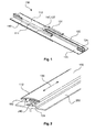
- Fig. 1 illustrates a seat rail cover 100 with a first longitudinal section 110 and a second longitudinal section 120.
- the first longitudinal section 110 comprises a first cover element 112 and a first support element 114.
- the second longitudinal section 120 comprises a second cover element 122 and a second support element 124.
- the first support element 114 extends in longitudinal direction of the seat rail cover 100 along the first longitudinal section 110 and the second support element 124 extends in longitudinal direction of the seat rail cover 100 along the second longitudinal section 120.
- the seat rail cover 100 illustrated in Fig. 1 is shown in the maximally extended state. In this state, the first and second cover elements 110, 120 as well as the first and second support elements 114, 124 overlap in longitudinal direction of the seat rail cover 100.
- first and second support element 114, 124 extend along the complete length of the seat rail cover 100.
- the complete length of the seat rail cover is supported by the first and second support elements 114, 124 with respect to a seat rail crown of a seat rail, except for the longitudinal extension of the gap between the first support element 114 and the first cover element 112, which is described below with regard to Fig. 4 .
- the first support element 114 is formed with a hollow cuboid.
- the first support element 114 and the first cover element 112 are spaced apart such that the second cover element 122 is movable in longitudinal direction of the seat rail cover between the first support element 114 and the first cover element 112.
- first support element 114 and the second support element 124 extend side by side to each other in longitudinal direction of the seat rail cover.
- first and second support element 114, 124 extend side by side to each other in an overlapping section 131 of the first cover element and the second cover element.
- the overlapping section 131 of the first and second cover elements extends along the complete length of the first and second cover element, in case these elements have the same length.
- Fig. 2 illustrates the seat rail cover 100 in a contracted state and mounted to a seat rail crown 240.
- the first cover element 112 overlaps the second cover element 122.
- the first and second support elements are arranged in the seat rail crown 240 which is formed as a longitudinal slot extending in longitudinal direction 130 of the seat rail 200.
- the seat rail crown 240 is substantially C-shaped and has two projections which are arranged opposite to the floor area of the seat rail crown. Between the two projections, an opened slot permits the insertion of the seat rail cover.
- the distance between the two projections of the seat rail crown and the width of the first and second support elements may be dimensioned such that the length of the seat rail cover can be adapted in the mounted state, i.e. the friction between the projections of the seat rail crown and the first and second support elements permits a longitudinal movement of at least one of the first and second support element in the mounted state.
- the width of the first and second support element may be increased which would lead to an increased friction in the mounted state between the support elements and the projections of the seat rail crown.
- the seat rail cover and the seat rail may be form locked or friction locked.
- the seat rail cover comprises a stop mechanism.
- This stop mechanism is illustrated in Figs. 3 and 4 and requires an interaction between the first and second support element.
- a second stopper element 127 is arranged.
- the counterpart of the second stopper element 127 is the first stopper element 117 arranged at the first support element 114 of the first longitudinal section 110.
- the first and second stopper elements 117, 127 may also be arranged at the cover elements of the first longitudinal section and second longitudinal section.
- the maximum extended state of the seat rail cover is determined by the positions of the first and second stopper elements. The maximum extended state is reached when the stopper elements mesh with each other or engage with each other such that no further extension movement is possible.
- the first and second stopper elements are formed with two lateral projections which are extending from one of the first and second support element towards the other one of the first and second support element, respectively.
- the first stopper element engages with the second stopper element and prevents further longitudinal extension of the seat rail cover.
- the second end section of the second longitudinal section is shown having a support element with two support ribs which are arranged symmetric with regard to the longitudinal direction of the second longitudinal direction.
- the second support element is formed of a single support rib, i.e., is formed asymmetric with regard to the longitudinal direction and in particular with regard to a longitudinal axis of the second cover element of the second longitudinal section provided that none of the ribs is attached in the centre of the second cover element.
- the first end section of the first longitudinal section is shown having a symmetric section of the first support element.
- the first support element is formed with a hollow cuboid which is arranged asymmetrically with regard to the longitudinal axis of the first cover element.
- the asymmetric sections of the first and second support elements overlap in longitudinal direction of the seat rail cover and they are located adjacent, in particular are immediately or directly adjacent, to each other in transversal direction of the seat rail cover.
- the first support element When mounting the first and second longitudinal sections to a seat rail cover, the first support element may be elastically bent or turned such that the first stopper element can pass the second stopper element. Subsequently, the first support element will take its initial position, i.e. before bending it away from the second support element, and when extending the seat rail cover now, the first and second stopper element do not permit passing each other.
- the seat rail cover may be made of elastically deformable material, such as plastic, for example.
- the first and second support element may extend towards the floor or ground surface of the seat rail crown such that a load dispersion of loads applied from the passenger cabin to the cover elements 112, 122 into the seat rail crown is achieved.
- Fig. 5 illustrates a seat rail 200 having a seat rail crown 240.
- a first projection 220 and a second projection 230 are arranged on an upper surface of the seat rail, i.e. pointing towards a passenger cabin or arranged at a level of the floor of the passenger cabin.
- the seat rail cover is located in the seat rail crown between the projections 220, 230.
- a seat leg 310 is arranged in the crown of the seat rail and is movable in longitudinal direction of the seat rail.
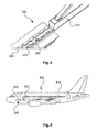
- Fig. 6 illustrates an aircraft 400 with a seat arrangement 250 with a seat rail 200 and a multitude of seats of which only one seat 300 is shown.
- the seat arrangement 250 is arranged in a passenger cabin 410 of the aircraft 400.
Landscapes
- Engineering & Computer Science (AREA)
- Aviation & Aerospace Engineering (AREA)
- Mechanical Engineering (AREA)
- Transportation (AREA)
- Seats For Vehicles (AREA)
Abstract
Description
- The invention relates to seat rail covers for seat rails in an internal room or a passenger cabin of a means of transport, a seat arrangement with such a seat rail cover, and an aircraft with such a seat arrangement.
- Seat rails may be arranged such as to mechanically couple one or more seats with a passenger cabin and in particular with structural elements located at the floor of a passenger cabin. A seat rail permits longitudinal movement of the seats arranged along and coupled to the seat rail such that a seat configuration and in particular a longitudinal distance between adjacent seats can be adapted. Hence, the seat rail longitudinally extends in direction of the desired movement direction of the seats coupled to the seat rail.
- A seat rail cover may be used for covering a seat rail as to avoid intrusion of particles such as dirt and dust, for example, in the crown of the seat rail which may impede the movement of a seat in the crown of the seat rail or may cause damage to the seat rail or the seat legs of seats attached to the seat rail.
- Further, a seat rail cover may be used for providing a flat floor, i.e. a floor in a passenger cabin without a recess, a protrusion, or a gap, for example as a result of the crown of the seat rail.
-
US 2011/0049296 Al describes a seat rail for attaching seats to the floor of a passenger cabin in an aircraft. -
US 2006/0097109 Al describes an adjustable seat track cover with a cable channel for routing a cable within the seat track cover. - It may be seen as the objective technical problem to provide a flexible seat rail cover which provides an increased mechanical strength and stability.
- This problem is solved by the subject matter of the independent claims. Further embodiments are described in the dependent claims and in the following description.
- According to a first aspect, a seat rail cover for a seat rail is provided. The seat rail cover comprises a first longitudinal section and a second longitudinal section. The first longitudinal section comprises a first cover element and a first support element. The first support element extends in a longitudinal direction of the seat rail cover and protrudes from the first cover element transversely to the longitudinal direction. The second longitudinal section comprises a second cover element and a second support element. The second support element extends in longitudinal direction and protrudes from the second cover element transversely to the longitudinal direction. The first longitudinal section is movable in longitudinal direction of the seat rail cover with respect to the second longitudinal direction from a non extended state to an extended state.
- A seat rail cover as described above and hereinafter permits covering a seat rail of a seat arrangement in such a manner that a distance between adjacent seats, i.e. between two seats arranged one behind the other with respect to the longitudinal direction, can be adjusted or adapted and the same seat rail cover can be used for covering varying lengths of the seat rail between two adjacent seats.
- The first longitudinal section and the second longitudinal section are movable with respect to each other according to the telescopic principle, i.e. the seat rail cover has a contracted state with the minimum length of the seat rail cover, an extended state with the maximum length of the seat rail cover, and a multitude of intermediate states in which the length of the seat rail cover is longer than the minimum length and shorter than the maximum length of the seat rail cover.
- The length of the first longitudinal section may be identical to the length of the second longitudinal section. In this case, when moving one of the first and second longitudinal sections such that it completely overlaps the other one of the first and second longitudinal sections, the length of the seat rail cover in the contracted state corresponds to the length of any one of the first or second longitudinal section.
- In one embodiment, the first longitudinal section and the second longitudinal section are continuously movable, i.e. stepless movable, with respect to each other.
- In one embodiment, the seat rail cover comprises a first end section and a second end section which are mechanically attachable to seats adjacent to each other. In this embodiment, the length of the seat rail cover may be automatically adjusted in case a seat of the adjacent seats is moved along the longitudinal direction of the seat rail.
- In one embodiment, the first longitudinal section and the second longitudinal section are brought to a determined length of the seat rail cover and are mechanically fixed with respect to each other such that the seat rail cover is adjusted to said length. When mounting the seat rail cover to a seat rail, the position of the seat rail cover may be fixed with respect to the seat rail.
- According to an embodiment, the first support element and the second support element continuously extend in longitudinal direction of the seat rail cover.
- The first support element continuously extends along the first longitudinal section and the second support element continuously extends along the second longitudinal section of the seat rail cover.
- Therefore, as the support elements continuously extend along the respective longitudinal section, loads applied to the respective cover element are being applied via the respective support element to the seat rail crown along the length of the first and second support element and the load distribution per area may be reduced.
- According to a further embodiment, the first support element and the second support element continuously extend in longitudinal direction of the seat rail cover in the extended state of the seat rail cover.
- In this embodiment, the first and second support element do not only continuously extend along the length of the respective cover element but in sum continuously extend in longitudinal direction of the seat rail cover. In other words, there is no gap or spacing between the first support element and the second support element.
- The first support element may continuously extend along the complete length of the first longitudinal section and the second support element may continuously extend along the complete length of the second longitudinal section.
- According to a further embodiment, the first support element and the second support element form an overlapping section in longitudinal direction of the seat rail cover in the extended state of the seat rail cover.
- In the overlapping section, the first support element and the second support element extend along the longitudinal direction side by side with respect to each other, in other words, the first and second support element form the overlapping section where they are arranged side by side to each other in longitudinal direction of the seat rail cover.
- The first support element and the second support element may be formed asymmetrically with respect to the longitudinal direction of the seat rail cover at least in a longitudinal section of the first and second support element, respectively, forming a first asymmetric longitudinal section and a second asymmetric longitudinal section of the first and second support element, respectively..
- An asymmetric arrangement of a support element is to be understood as having a transversal offset with regard to the longitudinal centre axis of a cover element. In a symmetric arrangement the support element is symmetric with regard to a longitudinal centre axis of the respective cover element.
- In a first end section of the first longitudinal section, the first support element may be symmetric with respect to a longitudinal direction of the seat rail cover. Similarly, in a second end section of the second longitudinal section, the second support element may be symmetric with respect to the longitudinal direction of the seat rail cover. In this embodiment, the first end section and the second end section may be arranged at opposite ends of the seat rail cover.
- In this embodiment, the overlapping section of the first and second support element is formed by the asymmetrically formed sections of the first and second support elements. The symmetric sections of the first and second support elements may be aligned to each other with respect to the longitudinal direction of the seat rail cover, i.e., the symmetric sections of the first and second support elements have no transversal offset with respect to each other.
- According to a further embodiment, the seat rail cover comprises a stop mechanism as to not permit extension of the seat rail cover over a maximum extension length. The stop mechanism may comprise a first stopper element at the first longitudinal section and a second stopper element at the second longitudinal section. The first and second stopper elements may be formed as to lie adjacent to each other or one on another in longitudinal direction of the seat rail cover in the maximum extended state.
- The second support element may comprise a longitudinal rib or fin which extends along the second support element in longitudinal direction of the first second support element.
- The first stopper element may be formed comb-shaped or with at least two teeth with a recess in between. In a mounted state of the seat rail cover, the longitudinal rib is located in the recess such that the first and second longitudinal sections can be moved with respect to each other in longitudinal direction of the seat rail cover.
- The recess of the first stopper element extends in a transversal direction of the seat rail cover. In a mounted state of the seat rail cover, the teeth of the first stopper element are arranged in a z-direction above each other, i.e. with respect to the seat rail in a direction up or down with respect to a ground surface of a seat rail crown and are pointing towards the longitudinal rib. The z-direction substantially corresponds to an insertion or removal direction of the seat rail cover to or from a seat rail and is perpendicular to the longitudinal direction and transversal direction of the seat rail cover.
- In this embodiment, the longitudinal rib is arranged in the recess between the teeth of the first stopper element. Therefore, the first and second support elements and thus the first and second longitudinal sections are mechanically coupled to each other such that a movement in z-direction of one of these elements with respect to the other one is prevented.
- In the mounted state, the first and second longitudinal sections are mechanically coupled to each other such that these parts form the seat rail cover.
- According to a further embodiment, the first and second support elements may be arranged adjacent to each other in the mounted state of the seat rail cover in the overlapping section in a direction transversal to the longitudinal section of the seat rail cover. In particular, the first and second support elements may contact one another in the mounted state in the overlapping section of the first and second support elements.
- In this embodiment, the first and second support elements are arranged such that a movement of the support elements and the longitudinal sections of the seat rail cover is avoided in a transversal direction of the seat rail cover. In other words, the longitudinal sections of the seat rail cover are mechanically fixed with respect to each other in the transversal direction of the seat rail cover, in particular in a direction perpendicular to the longitudinal direction of the seat rail cover.
- In other words, the support elements of the seat rail cover are formed such that a movement of one longitudinal section with respect to the other longitudinal section is permitted in longitudinal direction of the seat rail cover whereas a movement in transversal direction or in z-direction with respect to each other is prevented.
- In one embodiment, the lateral edges of the second cover element may be bent around the first cover element. This embodiment may further improve the fixation of the longitudinal sections and the mechanical stability and rigidity with respect to each other in lateral direction and in z-direction whereas a longitudinal movement is permitted.
- According to a further embodiment, the first support element and the second support element extend in longitudinal direction of the seat rail cover over the complete length of the seat rail cover.
- According to a further embodiment, the first support element is arranged perpendicular to the first cover element and the second support element is arranged perpendicular to the second cover element.
- In the mounted state of the seat rail cover, the first and second support elements extend into the crown of a seat rail, i.e. downwardly with respect to the floor of a passenger cabin.
- According to a further embodiment, a longitudinal section of the first support element is spaced apart from the first cover element to form a gap and the second cover element is located in the gap and adapted for moving in longitudinal direction in the gap.
- The first support element is spaced apart from the first cover element at least over a longitudinal section of the first cover element. When moving the second longitudinal section in longitudinal direction with respect to the first longitudinal section, the second cover element slides with respect to the first cover element through the gap between the first cover element and the first support element.
- According to a further embodiment, a longitudinal section of the first support element is formed of a hollow body.
- The first support element formed of a hollow body may provide a seat rail cover with a reduced weight and high mechanical strength.
- According to a further embodiment, the first support element is mechanically attached to the first cover element by an attachment structure and the second cover element comprises a longitudinal recess in the second cover element for accommodating the attachment structure in a non extended state of the seat rail cover.
- The attachment structure may be formed by a punctual or flat mechanical attachment of the first support element to the first cover element. When bringing or moving the first and second longitudinal section to the contracted state of the seat rail cover, the attachment structure moves into the recess in the second cover element and thus enables that the first and second longitudinal section overlap or completely overlap each other in longitudinal direction of the seat rail cover.
- According to a further aspect, a seat arrangement for a passenger cabin of a means of transportation is provided. The seat arrangement comprises a seat rail, a first seat and a second seat adjacent to the first seat in longitudinal direction of the seat rail and a seat rail cover as described above and hereinafter. The seat rail cover is arranged as to cover a seat rail crown of the seat rail between the first seat and the second seat. The means of transportation may be any one of a car, a bus, a train, a ship, or an aircraft. In other words, any means of transportation which are suitable for passenger transportation.
- The seat rail cover may be mechanically reversibly attached to both the first and second seats. Thus, when moving one of the first and second seats in longitudinal direction of the seat rail, the seat rail cover automatically adjusts its length to the new distance between the first and second seat, be it shorter or longer than the previous length of the seat rail cover.
- In one embodiment, the length of the first and second longitudinal sections is 10 inches (254 mm). Therefore, the minimum length of the seat rail cover is 10 inches (254 mm) and corresponds to the length of one of the first and second longitudinal section. The minimum length of the overlapping section may be 66 mm. In the fully extended state of the seat rail cover, the overlapping section has its minimum length and in the fully contracted state of the seat rail cover the overlapping section has its maximum length. Due to this minimum length of the overlapping section of 66 mm in this embodiment, the maximum length of the seat rail cover is 442 mm in the fully extended state.
- According to an embodiment, the first support element and the second support element are arranged in the seat rail crown of the seat rail.
- According to a further embodiment, the first longitudinal section is attached to a seat leg of the first seat.
- According to a further embodiment, the second longitudinal section is attached to a seat leg of the second seat.
- According to a further, aspect, an air craft is provided which comprises a seat arrangement as described above and hereinafter.
- According to an embodiment, the seat arrangement is arranged in a passenger cabin of the air craft.
- Exemplary embodiments of the seat rail cover will be elucidated with reference to the following drawings.
-
-
Fig. 1 illustrates an isometric view of the seat rail cover according to an exemplary embodiment in an extended state. -
Fig. 2 illustrates an isometric view of the seat rail cover according to an exemplary embodiment in a state mounted to a seat rail. -
Fig. 3 illustrates an isometric view of a second longitudinal section of a seat rail cover according to an exemplary embodiment. -
Fig. 4 illustrates an isometric view of a first longitudinal section of a seat rail cover according to an exemplary embodiment. -
Fig. 5 illustrates an isometric view of a seat arrangement. -
Fig. 6 illustrates a schematic view of an aircraft according to an exemplary embodiment. - The drawings are schematic and not to scale. Identical or similar reference signs relate to identical or similar elements.
-
Fig. 1 illustrates aseat rail cover 100 with a firstlongitudinal section 110 and a secondlongitudinal section 120. The firstlongitudinal section 110 comprises afirst cover element 112 and afirst support element 114. The secondlongitudinal section 120 comprises asecond cover element 122 and asecond support element 124. - The
first support element 114 extends in longitudinal direction of theseat rail cover 100 along the firstlongitudinal section 110 and thesecond support element 124 extends in longitudinal direction of theseat rail cover 100 along the secondlongitudinal section 120. - The
seat rail cover 100 illustrated inFig. 1 is shown in the maximally extended state. In this state, the first andsecond cover elements second support elements seat rail cover 100. - In sum, the first and
second support element seat rail cover 100. Thus, the complete length of the seat rail cover is supported by the first andsecond support elements first support element 114 and thefirst cover element 112, which is described below with regard toFig. 4 . - The
first support element 114 is formed with a hollow cuboid. Thefirst support element 114 and thefirst cover element 112 are spaced apart such that thesecond cover element 122 is movable in longitudinal direction of the seat rail cover between thefirst support element 114 and thefirst cover element 112. - In the contracted state of the seat rail cover, the
first support element 114 and thesecond support element 124 extend side by side to each other in longitudinal direction of the seat rail cover. In the extended state of the seat rail cover, the first andsecond support element section 131 of the first cover element and the second cover element. - In the contracted state of the seat rail cover, the overlapping
section 131 of the first and second cover elements extends along the complete length of the first and second cover element, in case these elements have the same length. -
Fig. 2 illustrates theseat rail cover 100 in a contracted state and mounted to aseat rail crown 240. Thefirst cover element 112 overlaps thesecond cover element 122. The first and second support elements are arranged in theseat rail crown 240 which is formed as a longitudinal slot extending inlongitudinal direction 130 of theseat rail 200. - The
seat rail crown 240 is substantially C-shaped and has two projections which are arranged opposite to the floor area of the seat rail crown. Between the two projections, an opened slot permits the insertion of the seat rail cover. - The distance between the two projections of the seat rail crown and the width of the first and second support elements may be dimensioned such that the length of the seat rail cover can be adapted in the mounted state, i.e. the friction between the projections of the seat rail crown and the first and second support elements permits a longitudinal movement of at least one of the first and second support element in the mounted state.
- In case such a longitudinal movement of one of the first and second support element in the mounted state is not desired, the width of the first and second support element may be increased which would lead to an increased friction in the mounted state between the support elements and the projections of the seat rail crown. However, the seat rail cover and the seat rail may be form locked or friction locked.
- As to not extend the seat rail cover beyond a maximum longitudinal extension, the seat rail cover comprises a stop mechanism. This stop mechanism is illustrated in
Figs. 3 and 4 and requires an interaction between the first and second support element. - At the
second support element 124 of the secondlongitudinal section 120, asecond stopper element 127 is arranged. - The counterpart of the
second stopper element 127 is thefirst stopper element 117 arranged at thefirst support element 114 of the firstlongitudinal section 110. - The first and
second stopper elements - The maximum extended state of the seat rail cover is determined by the positions of the first and second stopper elements. The maximum extended state is reached when the stopper elements mesh with each other or engage with each other such that no further extension movement is possible.
- In the example shown in
Figs. 3 and 4 , the first and second stopper elements are formed with two lateral projections which are extending from one of the first and second support element towards the other one of the first and second support element, respectively. In the maximum extended state, the first stopper element engages with the second stopper element and prevents further longitudinal extension of the seat rail cover. - In the right hand corner of
Fig. 3 , the second end section of the second longitudinal section is shown having a support element with two support ribs which are arranged symmetric with regard to the longitudinal direction of the second longitudinal direction. Further to the left, the second support element is formed of a single support rib, i.e., is formed asymmetric with regard to the longitudinal direction and in particular with regard to a longitudinal axis of the second cover element of the second longitudinal section provided that none of the ribs is attached in the centre of the second cover element. - Similarly, in the right hand upper corner of
Fig. 4 , the first end section of the first longitudinal section is shown having a symmetric section of the first support element. Further on in longitudinal direction towards the left hand lower corner ofFig. 3 , the first support element is formed with a hollow cuboid which is arranged asymmetrically with regard to the longitudinal axis of the first cover element. - As shown in
Fig. 1 , the asymmetric sections of the first and second support elements overlap in longitudinal direction of the seat rail cover and they are located adjacent, in particular are immediately or directly adjacent, to each other in transversal direction of the seat rail cover. - When mounting the first and second longitudinal sections to a seat rail cover, the first support element may be elastically bent or turned such that the first stopper element can pass the second stopper element. Subsequently, the first support element will take its initial position, i.e. before bending it away from the second support element, and when extending the seat rail cover now, the first and second stopper element do not permit passing each other.
- In the mounted state of the seat rail cover, a lateral movement of one of the first and second support element with respect to the other one of the first and second support element is not possible as both these elements are located in the seat rail crown. Thus, in the mounted state, the longitudinal extension of the seat rail cover cannot go beyond the maximum length defined by the positions of the first and second stopper elements.
- The seat rail cover may be made of elastically deformable material, such as plastic, for example.
- In the mounted state, the first and second support element may extend towards the floor or ground surface of the seat rail crown such that a load dispersion of loads applied from the passenger cabin to the
cover elements -
Fig. 5 illustrates aseat rail 200 having aseat rail crown 240. Afirst projection 220 and asecond projection 230 are arranged on an upper surface of the seat rail, i.e. pointing towards a passenger cabin or arranged at a level of the floor of the passenger cabin. The seat rail cover is located in the seat rail crown between theprojections - A
seat leg 310 is arranged in the crown of the seat rail and is movable in longitudinal direction of the seat rail. -
Fig. 6 illustrates anaircraft 400 with aseat arrangement 250 with aseat rail 200 and a multitude of seats of which only oneseat 300 is shown. Theseat arrangement 250 is arranged in apassenger cabin 410 of theaircraft 400. -
- 100
- seat rail cover
- 110
- first longitudinal section
- 112
- first cover element
- 114
- first support element
- 115
- attachment structure
- 116
- gap
- 117
- first stopper element
- 120
- second longitudinal section
- 122
- second cover element
- 124
- second support element
- 126
- recess
- 127
- second stopper element
- 130
- longitudinal direction
- 131
- overlapping section
- 200
- seat rail
- 220
- projection
- 230
- projection
- 240
- seat rail crown
- 250
- seat arrangement
- 300
- seat
- 310
- seat leg
- 400
- aircraft
- 410
- passenger cabin
Claims (15)
- Seat rail cover (100) for a seat rail (200), the seat rail cover comprising:a first longitudinal section (110); anda second longitudinal section (120);wherein the first longitudinal section (110) comprises a first cover element (112) and a first support element (114);wherein the first support element (114) extends in a longitudinal direction (130) of the seat rail cover (100) and protrudes from the first cover element (112) transversely to the longitudinal direction;wherein the second longitudinal section (120) comprises a second cover element (122) and a second support element (124);wherein the second support element (124) extends in longitudinal direction (130) and protrudes from the second cover element (122) transversely to the longitudinal direction;wherein the first longitudinal section (110) is movable in longitudinal direction (130) of the seat rail cover (100) with respect to the second longitudinal direction from a non extended state to an extended state.
- Seat rail cover (100) according to claim 1,
wherein the first support element (114) and the second support element (124) continuously extend in longitudinal direction of the seat rail cover (100). - Seat rail cover (100) according to claim 1 or 2,
wherein in the extended state the first support element (114) and the second support element (124) continuously extend in longitudinal direction of the seat rail cover (100). - Seat rail cover (100) according to any one of the preceding claims,
wherein in the extended state the first support element (114) and the second support element (124) form an overlapping section (131) in longitudinal direction of the seat rail cover. - Seat rail cover (100) according to any one of the preceding claims,
wherein the first support element (114) and the second support element (124) extend in longitudinal direction of the seat rail cover over the complete length of the seat rail cover. - Seat rail cover (100) according to any one of the preceding claims,
wherein the first support element (114) is arranged perpendicular to the first cover element (112); and
wherein the second support element (124) is arranged perpendicular to the second cover element (122). - Seat rail cover (100) according to any one of the preceding claims,
wherein a longitudinal section of the first support element (114) is spaced apart from the first cover element (112) to form a gap (116);
wherein the second cover element (122) is located in the gap (116) and adapted for moving in longitudinal direction in the gap. - Seat rail cover (100) according to any one of the preceding claims,
wherein a longitudinal section of the first support element (114) is formed of a hollow body. - Seat rail cover (100) according to any one of the preceding claims,
wherein the first support element (114) is mechanically attached to the first cover element (112) by an attachment structure (115);
wherein the second cover element (122) comprises a longitudinal recess (126) for accommodating the attachment structure (115) in a non extended state of the seat rail cover. - Seat arrangement (250) for a passenger cabin (410) of a means of transportation, the seat arrangement (250) comprising:a seat rail (200);a first seat (310) and a second seat adjacent to the first seat in longitudinal direction of the seat rail (250);a seat rail cover (100) according to any one of claims 1 to 9;wherein the seat rail cover (100) is arranged as to cover a seat rail crown (240) of the seat rail (200) between the first seat and the second seat.
- Seat arrangement (250) according to claim 10,
wherein the first support element (114) and the second support element (124) are arranged in the seat rail crown (240) of the seat rail (200). - Seat arrangement (250) according to claim 10 or 11, wherein the first longitudinal section (110) is attached to a seat leg of the first seat.
- Seat arrangement (250) according to any one of claims 10 to 12, wherein the second longitudinal section (120) is attached to a seat leg of the second seat.
- Air craft (400), comprising a seat arrangement (250) according to any one of claims 10 to 13.
- Air craft (400), wherein the seat arrangement (250) is arranged in a passenger cabin.
Priority Applications (3)
| Application Number | Priority Date | Filing Date | Title |
|---|---|---|---|
| EP13194040.5A EP2876048B1 (en) | 2013-11-22 | 2013-11-22 | Telescopic seat rail cover |
| US14/546,155 US9592903B2 (en) | 2013-11-22 | 2014-11-18 | Telescopic seat rail cover |
| CN201410676055.4A CN104648189B (en) | 2013-11-22 | 2014-11-21 | Seat rail cover, seat device and aircraft |
Applications Claiming Priority (1)
| Application Number | Priority Date | Filing Date | Title |
|---|---|---|---|
| EP13194040.5A EP2876048B1 (en) | 2013-11-22 | 2013-11-22 | Telescopic seat rail cover |
Publications (2)
| Publication Number | Publication Date |
|---|---|
| EP2876048A1 true EP2876048A1 (en) | 2015-05-27 |
| EP2876048B1 EP2876048B1 (en) | 2018-08-01 |
Family
ID=49639768
Family Applications (1)
| Application Number | Title | Priority Date | Filing Date |
|---|---|---|---|
| EP13194040.5A Not-in-force EP2876048B1 (en) | 2013-11-22 | 2013-11-22 | Telescopic seat rail cover |
Country Status (3)
| Country | Link |
|---|---|
| US (1) | US9592903B2 (en) |
| EP (1) | EP2876048B1 (en) |
| CN (1) | CN104648189B (en) |
Cited By (3)
| Publication number | Priority date | Publication date | Assignee | Title |
|---|---|---|---|---|
| DE102017107021A1 (en) | 2017-03-31 | 2018-10-04 | Airbus Operations Gmbh | Seat rail cover |
| US10688887B2 (en) | 2017-08-30 | 2020-06-23 | Toyota Boshoku Kabushiki Kaisha | Sliding device |
| US11325505B2 (en) | 2018-11-02 | 2022-05-10 | Toyota Boshoku Kabushiki Kaisha | Sliding device |
Families Citing this family (12)
| Publication number | Priority date | Publication date | Assignee | Title |
|---|---|---|---|---|
| DE102015116591A1 (en) * | 2015-09-30 | 2017-03-30 | Airbus Operations Gmbh | Profile for joining a floor structure and sealing system for a floor structure |
| DE102016206386A1 (en) * | 2016-04-15 | 2017-10-19 | Airbus Operations Gmbh | Seat rail cover for covering a seat rail in a vehicle floor and method for manufacturing a seat rail cover |
| WO2018207239A1 (en) * | 2017-05-08 | 2018-11-15 | Ykk株式会社 | Motion guiding device and groove shield unit |
| JP2019094944A (en) * | 2017-11-20 | 2019-06-20 | Thk株式会社 | Rail cover of motion guide device |
| DE102018108304B4 (en) * | 2018-04-09 | 2026-02-05 | Airbus Operations Gmbh | Rail system and passenger seating system for a vehicle cabin and vehicle with a cabin |
| DE102018108296B4 (en) * | 2018-04-09 | 2022-04-21 | Airbus Operations Gmbh | Rail cover for a slide seat rail between two passenger seats in a cabin of a vehicle, a passenger seating system and a vehicle |
| DE102018126012A1 (en) * | 2018-10-19 | 2020-04-23 | Airbus Operations Gmbh | Rail arrangement for an interior of an aircraft |
| US11560072B2 (en) * | 2019-03-29 | 2023-01-24 | The Boeing Company | Seat track covering systems and methods |
| US10793278B1 (en) * | 2019-03-29 | 2020-10-06 | The Boeing Company | Seat positioning systems and methods |
| US10791657B1 (en) * | 2020-04-09 | 2020-09-29 | Aerion International Property Management Corporation | Composite aircraft structures with dividers for shielding and protecting cables and wires |
| US11447270B2 (en) * | 2020-06-22 | 2022-09-20 | The Boeing Company | Track filler and methods for installing the track filler |
| US12570222B2 (en) * | 2023-11-15 | 2026-03-10 | Atieva, Inc. | Cover assemblies for seat rail at vehicle floor |
Citations (2)
| Publication number | Priority date | Publication date | Assignee | Title |
|---|---|---|---|---|
| US20060097109A1 (en) * | 2004-11-08 | 2006-05-11 | Laib Trevor M | Telescoping powered seat track cover |
| US20100052386A1 (en) * | 2008-08-28 | 2010-03-04 | Phinney Randy R | Low maintenance configuration for sliding seats |
Family Cites Families (4)
| Publication number | Priority date | Publication date | Assignee | Title |
|---|---|---|---|---|
| FR2527162A1 (en) * | 1982-05-18 | 1983-11-25 | Tissmetal Lionel Dupont | DEVICE FOR PROTECTING AND COVERING A RAIL FOR ATTACHING THE SEATS OF A COMMERCIAL AIRCRAFT EQUIPPED WITH A DEVICE FOR AUTOMATIC VARIATION OF THE SEAT OF THE SEATS |
| JP4376928B2 (en) * | 2007-08-10 | 2009-12-02 | トヨタ自動車株式会社 | Vehicle seat slide structure |
| DE102009039581A1 (en) | 2009-09-01 | 2011-03-17 | Airbus Operations Gmbh | Hard oxidized coated seat rail |
| DE102013105418A1 (en) * | 2013-05-27 | 2014-12-11 | Airbus Operations Gmbh | Length-variable rail cover for a seat rail |
-
2013
- 2013-11-22 EP EP13194040.5A patent/EP2876048B1/en not_active Not-in-force
-
2014
- 2014-11-18 US US14/546,155 patent/US9592903B2/en not_active Expired - Fee Related
- 2014-11-21 CN CN201410676055.4A patent/CN104648189B/en not_active Expired - Fee Related
Patent Citations (2)
| Publication number | Priority date | Publication date | Assignee | Title |
|---|---|---|---|---|
| US20060097109A1 (en) * | 2004-11-08 | 2006-05-11 | Laib Trevor M | Telescoping powered seat track cover |
| US20100052386A1 (en) * | 2008-08-28 | 2010-03-04 | Phinney Randy R | Low maintenance configuration for sliding seats |
Cited By (8)
| Publication number | Priority date | Publication date | Assignee | Title |
|---|---|---|---|---|
| DE102017107021A1 (en) | 2017-03-31 | 2018-10-04 | Airbus Operations Gmbh | Seat rail cover |
| US10450073B2 (en) | 2017-03-31 | 2019-10-22 | Airbus Operations Gmbh | Seat track cover |
| US10688887B2 (en) | 2017-08-30 | 2020-06-23 | Toyota Boshoku Kabushiki Kaisha | Sliding device |
| US10752131B2 (en) | 2017-08-30 | 2020-08-25 | Toyota Boshoku Kabushiki Kaisha | Sliding device |
| US10919414B2 (en) | 2017-08-30 | 2021-02-16 | Toyota Boshoku Kabushiki Kaisha | Sliding device |
| DE102018214161B4 (en) | 2017-08-30 | 2022-11-03 | Toyota Boshoku Kabushiki Kaisha | SLIDE DEVICE |
| DE102018214162B4 (en) | 2017-08-30 | 2023-10-05 | Toyota Boshoku Kabushiki Kaisha | SLIDING DEVICE |
| US11325505B2 (en) | 2018-11-02 | 2022-05-10 | Toyota Boshoku Kabushiki Kaisha | Sliding device |
Also Published As
| Publication number | Publication date |
|---|---|
| CN104648189A (en) | 2015-05-27 |
| CN104648189B (en) | 2017-05-24 |
| US9592903B2 (en) | 2017-03-14 |
| US20150145298A1 (en) | 2015-05-28 |
| EP2876048B1 (en) | 2018-08-01 |
Similar Documents
| Publication | Publication Date | Title |
|---|---|---|
| EP2876048B1 (en) | Telescopic seat rail cover | |
| US9868528B2 (en) | Divider element for an aircraft cabin | |
| US10315594B2 (en) | Slide wiring apparatus | |
| US20190054868A1 (en) | Slide wiring device | |
| US20150284084A1 (en) | Foldable divider device for an aircraft cabin | |
| US9045024B2 (en) | Lower rail structure of sliding door for vehicle | |
| US11214176B2 (en) | Rail covering for a sliding seat rail between two passenger seats in a cabin of a vehicle | |
| US20150145302A1 (en) | Adjustable seat cushion assembly | |
| US10710727B2 (en) | Seat system for a cabin of a transportation means with a compactable seat row | |
| EP2954602B1 (en) | Side wall bracket for cable tray | |
| US20120145831A1 (en) | Floor of a dome module as an interface between an air passenger bridge or air passenger stairs and an airplane | |
| US9248911B2 (en) | Variable-length rail cover | |
| CN104071039A (en) | Seat track end cap and advancing stopping seat position sensor | |
| CN110462954B (en) | Exterior body and wire harness | |
| DE112013004193B4 (en) | Management structure for electrical cables | |
| US20140349042A1 (en) | Variable-Length Rail Cover For A Seat Rail | |
| US8100360B2 (en) | Light rail system for powered introduction of large loads in a structure | |
| EP3296461A1 (en) | Cable management assembly | |
| CN104349951B (en) | Luffer boards Wiper blade device | |
| US9914345B2 (en) | Wind protection device on a closable roof opening portion of a motor vehicle | |
| JP6769018B2 (en) | Shutter structure | |
| EP4585512A1 (en) | Connecting element structure, cabin and a vehicle comprising such cabin | |
| JP6225936B2 (en) | Wire harness wiring device for slide sheet | |
| JP4878780B2 (en) | Wire harness holding structure | |
| JP2015116036A (en) | Offset clip |
Legal Events
| Date | Code | Title | Description |
|---|---|---|---|
| PUAI | Public reference made under article 153(3) epc to a published international application that has entered the european phase |
Free format text: ORIGINAL CODE: 0009012 |
|
| 17P | Request for examination filed |
Effective date: 20131122 |
|
| AK | Designated contracting states |
Kind code of ref document: A1 Designated state(s): AL AT BE BG CH CY CZ DE DK EE ES FI FR GB GR HR HU IE IS IT LI LT LU LV MC MK MT NL NO PL PT RO RS SE SI SK SM TR |
|
| AX | Request for extension of the european patent |
Extension state: BA ME |
|
| R17P | Request for examination filed (corrected) |
Effective date: 20150806 |
|
| RBV | Designated contracting states (corrected) |
Designated state(s): AL AT BE BG CH CY CZ DE DK EE ES FI FR GB GR HR HU IE IS IT LI LT LU LV MC MK MT NL NO PL PT RO RS SE SI SK SM TR |
|
| GRAP | Despatch of communication of intention to grant a patent |
Free format text: ORIGINAL CODE: EPIDOSNIGR1 |
|
| STAA | Information on the status of an ep patent application or granted ep patent |
Free format text: STATUS: GRANT OF PATENT IS INTENDED |
|
| INTG | Intention to grant announced |
Effective date: 20180430 |
|
| GRAS | Grant fee paid |
Free format text: ORIGINAL CODE: EPIDOSNIGR3 |
|
| GRAA | (expected) grant |
Free format text: ORIGINAL CODE: 0009210 |
|
| STAA | Information on the status of an ep patent application or granted ep patent |
Free format text: STATUS: THE PATENT HAS BEEN GRANTED |
|
| AK | Designated contracting states |
Kind code of ref document: B1 Designated state(s): AL AT BE BG CH CY CZ DE DK EE ES FI FR GB GR HR HU IE IS IT LI LT LU LV MC MK MT NL NO PL PT RO RS SE SI SK SM TR |
|
| REG | Reference to a national code |
Ref country code: GB Ref legal event code: FG4D |
|
| REG | Reference to a national code |
Ref country code: CH Ref legal event code: EP Ref country code: AT Ref legal event code: REF Ref document number: 1023980 Country of ref document: AT Kind code of ref document: T Effective date: 20180815 |
|
| REG | Reference to a national code |
Ref country code: IE Ref legal event code: FG4D |
|
| REG | Reference to a national code |
Ref country code: DE Ref legal event code: R096 Ref document number: 602013041101 Country of ref document: DE |
|
| REG | Reference to a national code |
Ref country code: NL Ref legal event code: MP Effective date: 20180801 |
|
| REG | Reference to a national code |
Ref country code: LT Ref legal event code: MG4D |
|
| REG | Reference to a national code |
Ref country code: AT Ref legal event code: MK05 Ref document number: 1023980 Country of ref document: AT Kind code of ref document: T Effective date: 20180801 |
|
| PG25 | Lapsed in a contracting state [announced via postgrant information from national office to epo] |
Ref country code: GR Free format text: LAPSE BECAUSE OF FAILURE TO SUBMIT A TRANSLATION OF THE DESCRIPTION OR TO PAY THE FEE WITHIN THE PRESCRIBED TIME-LIMIT Effective date: 20181102 Ref country code: NO Free format text: LAPSE BECAUSE OF FAILURE TO SUBMIT A TRANSLATION OF THE DESCRIPTION OR TO PAY THE FEE WITHIN THE PRESCRIBED TIME-LIMIT Effective date: 20181101 Ref country code: AT Free format text: LAPSE BECAUSE OF FAILURE TO SUBMIT A TRANSLATION OF THE DESCRIPTION OR TO PAY THE FEE WITHIN THE PRESCRIBED TIME-LIMIT Effective date: 20180801 Ref country code: LT Free format text: LAPSE BECAUSE OF FAILURE TO SUBMIT A TRANSLATION OF THE DESCRIPTION OR TO PAY THE FEE WITHIN THE PRESCRIBED TIME-LIMIT Effective date: 20180801 Ref country code: BG Free format text: LAPSE BECAUSE OF FAILURE TO SUBMIT A TRANSLATION OF THE DESCRIPTION OR TO PAY THE FEE WITHIN THE PRESCRIBED TIME-LIMIT Effective date: 20181101 Ref country code: NL Free format text: LAPSE BECAUSE OF FAILURE TO SUBMIT A TRANSLATION OF THE DESCRIPTION OR TO PAY THE FEE WITHIN THE PRESCRIBED TIME-LIMIT Effective date: 20180801 Ref country code: FI Free format text: LAPSE BECAUSE OF FAILURE TO SUBMIT A TRANSLATION OF THE DESCRIPTION OR TO PAY THE FEE WITHIN THE PRESCRIBED TIME-LIMIT Effective date: 20180801 Ref country code: PL Free format text: LAPSE BECAUSE OF FAILURE TO SUBMIT A TRANSLATION OF THE DESCRIPTION OR TO PAY THE FEE WITHIN THE PRESCRIBED TIME-LIMIT Effective date: 20180801 Ref country code: IS Free format text: LAPSE BECAUSE OF FAILURE TO SUBMIT A TRANSLATION OF THE DESCRIPTION OR TO PAY THE FEE WITHIN THE PRESCRIBED TIME-LIMIT Effective date: 20181201 Ref country code: RS Free format text: LAPSE BECAUSE OF FAILURE TO SUBMIT A TRANSLATION OF THE DESCRIPTION OR TO PAY THE FEE WITHIN THE PRESCRIBED TIME-LIMIT Effective date: 20180801 Ref country code: SE Free format text: LAPSE BECAUSE OF FAILURE TO SUBMIT A TRANSLATION OF THE DESCRIPTION OR TO PAY THE FEE WITHIN THE PRESCRIBED TIME-LIMIT Effective date: 20180801 |
|
| PG25 | Lapsed in a contracting state [announced via postgrant information from national office to epo] |
Ref country code: AL Free format text: LAPSE BECAUSE OF FAILURE TO SUBMIT A TRANSLATION OF THE DESCRIPTION OR TO PAY THE FEE WITHIN THE PRESCRIBED TIME-LIMIT Effective date: 20180801 Ref country code: LV Free format text: LAPSE BECAUSE OF FAILURE TO SUBMIT A TRANSLATION OF THE DESCRIPTION OR TO PAY THE FEE WITHIN THE PRESCRIBED TIME-LIMIT Effective date: 20180801 Ref country code: HR Free format text: LAPSE BECAUSE OF FAILURE TO SUBMIT A TRANSLATION OF THE DESCRIPTION OR TO PAY THE FEE WITHIN THE PRESCRIBED TIME-LIMIT Effective date: 20180801 |
|
| PG25 | Lapsed in a contracting state [announced via postgrant information from national office to epo] |
Ref country code: EE Free format text: LAPSE BECAUSE OF FAILURE TO SUBMIT A TRANSLATION OF THE DESCRIPTION OR TO PAY THE FEE WITHIN THE PRESCRIBED TIME-LIMIT Effective date: 20180801 Ref country code: IT Free format text: LAPSE BECAUSE OF FAILURE TO SUBMIT A TRANSLATION OF THE DESCRIPTION OR TO PAY THE FEE WITHIN THE PRESCRIBED TIME-LIMIT Effective date: 20180801 Ref country code: RO Free format text: LAPSE BECAUSE OF FAILURE TO SUBMIT A TRANSLATION OF THE DESCRIPTION OR TO PAY THE FEE WITHIN THE PRESCRIBED TIME-LIMIT Effective date: 20180801 Ref country code: ES Free format text: LAPSE BECAUSE OF FAILURE TO SUBMIT A TRANSLATION OF THE DESCRIPTION OR TO PAY THE FEE WITHIN THE PRESCRIBED TIME-LIMIT Effective date: 20180801 Ref country code: CZ Free format text: LAPSE BECAUSE OF FAILURE TO SUBMIT A TRANSLATION OF THE DESCRIPTION OR TO PAY THE FEE WITHIN THE PRESCRIBED TIME-LIMIT Effective date: 20180801 |
|
| REG | Reference to a national code |
Ref country code: DE Ref legal event code: R097 Ref document number: 602013041101 Country of ref document: DE |
|
| PG25 | Lapsed in a contracting state [announced via postgrant information from national office to epo] |
Ref country code: SK Free format text: LAPSE BECAUSE OF FAILURE TO SUBMIT A TRANSLATION OF THE DESCRIPTION OR TO PAY THE FEE WITHIN THE PRESCRIBED TIME-LIMIT Effective date: 20180801 Ref country code: DK Free format text: LAPSE BECAUSE OF FAILURE TO SUBMIT A TRANSLATION OF THE DESCRIPTION OR TO PAY THE FEE WITHIN THE PRESCRIBED TIME-LIMIT Effective date: 20180801 Ref country code: SM Free format text: LAPSE BECAUSE OF FAILURE TO SUBMIT A TRANSLATION OF THE DESCRIPTION OR TO PAY THE FEE WITHIN THE PRESCRIBED TIME-LIMIT Effective date: 20180801 |
|
| PLBE | No opposition filed within time limit |
Free format text: ORIGINAL CODE: 0009261 |
|
| STAA | Information on the status of an ep patent application or granted ep patent |
Free format text: STATUS: NO OPPOSITION FILED WITHIN TIME LIMIT |
|
| REG | Reference to a national code |
Ref country code: CH Ref legal event code: PL |
|
| 26N | No opposition filed |
Effective date: 20190503 |
|
| PG25 | Lapsed in a contracting state [announced via postgrant information from national office to epo] |
Ref country code: MC Free format text: LAPSE BECAUSE OF FAILURE TO SUBMIT A TRANSLATION OF THE DESCRIPTION OR TO PAY THE FEE WITHIN THE PRESCRIBED TIME-LIMIT Effective date: 20180801 Ref country code: LU Free format text: LAPSE BECAUSE OF NON-PAYMENT OF DUE FEES Effective date: 20181122 |
|
| REG | Reference to a national code |
Ref country code: BE Ref legal event code: MM Effective date: 20181130 |
|
| REG | Reference to a national code |
Ref country code: IE Ref legal event code: MM4A |
|
| PG25 | Lapsed in a contracting state [announced via postgrant information from national office to epo] |
Ref country code: CH Free format text: LAPSE BECAUSE OF NON-PAYMENT OF DUE FEES Effective date: 20181130 Ref country code: LI Free format text: LAPSE BECAUSE OF NON-PAYMENT OF DUE FEES Effective date: 20181130 Ref country code: SI Free format text: LAPSE BECAUSE OF FAILURE TO SUBMIT A TRANSLATION OF THE DESCRIPTION OR TO PAY THE FEE WITHIN THE PRESCRIBED TIME-LIMIT Effective date: 20180801 |
|
| PG25 | Lapsed in a contracting state [announced via postgrant information from national office to epo] |
Ref country code: IE Free format text: LAPSE BECAUSE OF NON-PAYMENT OF DUE FEES Effective date: 20181122 |
|
| PG25 | Lapsed in a contracting state [announced via postgrant information from national office to epo] |
Ref country code: BE Free format text: LAPSE BECAUSE OF NON-PAYMENT OF DUE FEES Effective date: 20181130 |
|
| PG25 | Lapsed in a contracting state [announced via postgrant information from national office to epo] |
Ref country code: MT Free format text: LAPSE BECAUSE OF NON-PAYMENT OF DUE FEES Effective date: 20181122 |
|
| PGFP | Annual fee paid to national office [announced via postgrant information from national office to epo] |
Ref country code: FR Payment date: 20191120 Year of fee payment: 7 |
|
| PG25 | Lapsed in a contracting state [announced via postgrant information from national office to epo] |
Ref country code: TR Free format text: LAPSE BECAUSE OF FAILURE TO SUBMIT A TRANSLATION OF THE DESCRIPTION OR TO PAY THE FEE WITHIN THE PRESCRIBED TIME-LIMIT Effective date: 20180801 |
|
| PGFP | Annual fee paid to national office [announced via postgrant information from national office to epo] |
Ref country code: GB Payment date: 20191120 Year of fee payment: 7 |
|
| PG25 | Lapsed in a contracting state [announced via postgrant information from national office to epo] |
Ref country code: PT Free format text: LAPSE BECAUSE OF FAILURE TO SUBMIT A TRANSLATION OF THE DESCRIPTION OR TO PAY THE FEE WITHIN THE PRESCRIBED TIME-LIMIT Effective date: 20180801 |
|
| PG25 | Lapsed in a contracting state [announced via postgrant information from national office to epo] |
Ref country code: CY Free format text: LAPSE BECAUSE OF FAILURE TO SUBMIT A TRANSLATION OF THE DESCRIPTION OR TO PAY THE FEE WITHIN THE PRESCRIBED TIME-LIMIT Effective date: 20180801 Ref country code: HU Free format text: LAPSE BECAUSE OF FAILURE TO SUBMIT A TRANSLATION OF THE DESCRIPTION OR TO PAY THE FEE WITHIN THE PRESCRIBED TIME-LIMIT; INVALID AB INITIO Effective date: 20131122 Ref country code: MK Free format text: LAPSE BECAUSE OF NON-PAYMENT OF DUE FEES Effective date: 20180801 |
|
| GBPC | Gb: european patent ceased through non-payment of renewal fee |
Effective date: 20201122 |
|
| PG25 | Lapsed in a contracting state [announced via postgrant information from national office to epo] |
Ref country code: FR Free format text: LAPSE BECAUSE OF NON-PAYMENT OF DUE FEES Effective date: 20201130 |
|
| PG25 | Lapsed in a contracting state [announced via postgrant information from national office to epo] |
Ref country code: GB Free format text: LAPSE BECAUSE OF NON-PAYMENT OF DUE FEES Effective date: 20201122 |
|
| PGFP | Annual fee paid to national office [announced via postgrant information from national office to epo] |
Ref country code: DE Payment date: 20211118 Year of fee payment: 9 |
|
| REG | Reference to a national code |
Ref country code: DE Ref legal event code: R119 Ref document number: 602013041101 Country of ref document: DE |
|
| PG25 | Lapsed in a contracting state [announced via postgrant information from national office to epo] |
Ref country code: DE Free format text: LAPSE BECAUSE OF NON-PAYMENT OF DUE FEES Effective date: 20230601 |