EP2876042A1 - Helicopter Airframe - Google Patents
Helicopter Airframe Download PDFInfo
- Publication number
- EP2876042A1 EP2876042A1 EP13400030.6A EP13400030A EP2876042A1 EP 2876042 A1 EP2876042 A1 EP 2876042A1 EP 13400030 A EP13400030 A EP 13400030A EP 2876042 A1 EP2876042 A1 EP 2876042A1
- Authority
- EP
- European Patent Office
- Prior art keywords
- ribs
- shell
- bottom shell
- longitudinal
- floor panels
- Prior art date
- Legal status (The legal status is an assumption and is not a legal conclusion. Google has not performed a legal analysis and makes no representation as to the accuracy of the status listed.)
- Granted
Links
- 239000002828 fuel tank Substances 0.000 claims abstract description 9
- 239000012528 membrane Substances 0.000 claims description 35
- 239000000463 material Substances 0.000 claims description 4
- 238000000926 separation method Methods 0.000 claims description 4
- 239000004744 fabric Substances 0.000 claims description 3
- 229920002430 Fibre-reinforced plastic Polymers 0.000 claims description 2
- 239000011151 fibre-reinforced plastic Substances 0.000 claims description 2
- -1 mesh Substances 0.000 claims 1
- 239000004033 plastic Substances 0.000 claims 1
- 229920003023 plastic Polymers 0.000 claims 1
- 238000004519 manufacturing process Methods 0.000 description 7
- 239000000446 fuel Substances 0.000 description 6
- 239000006096 absorbing agent Substances 0.000 description 3
- 238000010276 construction Methods 0.000 description 3
- 230000010354 integration Effects 0.000 description 3
- 238000010521 absorption reaction Methods 0.000 description 2
- 230000000694 effects Effects 0.000 description 2
- 239000011888 foil Substances 0.000 description 2
- 230000002706 hydrostatic effect Effects 0.000 description 2
- 238000005304 joining Methods 0.000 description 2
- 230000006641 stabilisation Effects 0.000 description 2
- 238000011105 stabilization Methods 0.000 description 2
- 206010046530 Urinary bladder rupture Diseases 0.000 description 1
- 238000006243 chemical reaction Methods 0.000 description 1
- 238000009826 distribution Methods 0.000 description 1
- 230000008030 elimination Effects 0.000 description 1
- 238000003379 elimination reaction Methods 0.000 description 1
- 239000003733 fiber-reinforced composite Substances 0.000 description 1
- 238000000034 method Methods 0.000 description 1
- 238000000275 quality assurance Methods 0.000 description 1
- 230000002787 reinforcement Effects 0.000 description 1
- 238000007789 sealing Methods 0.000 description 1
- 239000003351 stiffener Substances 0.000 description 1
- 235000012773 waffles Nutrition 0.000 description 1
Images




Classifications
-
- B—PERFORMING OPERATIONS; TRANSPORTING
- B64—AIRCRAFT; AVIATION; COSMONAUTICS
- B64C—AEROPLANES; HELICOPTERS
- B64C1/00—Fuselages; Constructional features common to fuselages, wings, stabilising surfaces or the like
- B64C1/18—Floors
-
- B—PERFORMING OPERATIONS; TRANSPORTING
- B64—AIRCRAFT; AVIATION; COSMONAUTICS
- B64C—AEROPLANES; HELICOPTERS
- B64C1/00—Fuselages; Constructional features common to fuselages, wings, stabilising surfaces or the like
- B64C1/06—Frames; Stringers; Longerons ; Fuselage sections
- B64C1/061—Frames
- B64C1/062—Frames specially adapted to absorb crash loads
-
- B—PERFORMING OPERATIONS; TRANSPORTING
- B64—AIRCRAFT; AVIATION; COSMONAUTICS
- B64D—EQUIPMENT FOR FITTING IN OR TO AIRCRAFT; FLIGHT SUITS; PARACHUTES; ARRANGEMENT OR MOUNTING OF POWER PLANTS OR PROPULSION TRANSMISSIONS IN AIRCRAFT
- B64D37/00—Arrangements in connection with fuel supply for power plant
- B64D37/02—Tanks
- B64D37/04—Arrangement thereof in or on aircraft
-
- B—PERFORMING OPERATIONS; TRANSPORTING
- B64—AIRCRAFT; AVIATION; COSMONAUTICS
- B64D—EQUIPMENT FOR FITTING IN OR TO AIRCRAFT; FLIGHT SUITS; PARACHUTES; ARRANGEMENT OR MOUNTING OF POWER PLANTS OR PROPULSION TRANSMISSIONS IN AIRCRAFT
- B64D37/00—Arrangements in connection with fuel supply for power plant
- B64D37/02—Tanks
- B64D37/06—Constructional adaptations thereof
-
- B—PERFORMING OPERATIONS; TRANSPORTING
- B64—AIRCRAFT; AVIATION; COSMONAUTICS
- B64C—AEROPLANES; HELICOPTERS
- B64C27/00—Rotorcraft; Rotors peculiar thereto
- B64C27/04—Helicopters
-
- Y—GENERAL TAGGING OF NEW TECHNOLOGICAL DEVELOPMENTS; GENERAL TAGGING OF CROSS-SECTIONAL TECHNOLOGIES SPANNING OVER SEVERAL SECTIONS OF THE IPC; TECHNICAL SUBJECTS COVERED BY FORMER USPC CROSS-REFERENCE ART COLLECTIONS [XRACs] AND DIGESTS
- Y02—TECHNOLOGIES OR APPLICATIONS FOR MITIGATION OR ADAPTATION AGAINST CLIMATE CHANGE
- Y02T—CLIMATE CHANGE MITIGATION TECHNOLOGIES RELATED TO TRANSPORTATION
- Y02T50/00—Aeronautics or air transport
- Y02T50/40—Weight reduction
Definitions
- the invention relates to a helicopter airframe with a specific architecture of a subfloor structure with the features of the preamble of claim 1.
- a subfloor structure of a helicopter is arranged within the lower part of the airframe between the cabin floor level and the outer loft of the helicopter.
- a subfloor structure comprises a bottom shell, floor panels and a framework construction which connects to the floor and the bottom shell.
- the framework comprises interconnected longerons and ribs as well as the lower portion of the main frames.
- the longerons are longitudinal beam elements being basically arranged along the longitudinal axis of the aircraft and spanning the entire length of the subfloor structure, whereas the ribs are crossbeams which are basically arranged orthogonally to the longitudinal aircraft axis and span the whole subfloor width at their respective location.
- Both, the longerons and the ribs extend from the bottom shell to the floor plane and are basically flat stiffened webs with two caps arranged at both longitudinal borders of the web.
- the framework adopts an orthogonal waffle grid configuration with numerous intersections.
- the flat webs of both the longerons and the ribs are basically perpendicular to the floor plane.
- the tasks of the subfloor structure are manifold.
- the subfloor structure takes on the one hand the payload loads and transmits them to the main frames.
- the subfloor structure houses electrical and mechanical systems and the fuel tanks and further provides for substantial kinetic energy absorption in case of a crash scenario.
- the longerons confine, together with corresponding crossbeams, the fuel tank compartments in which elastomeric bladders are installed.
- lateral volumes enclosed between the longerons and curved side shells of the bottom shell are used for systems housing.
- the document US 6959894 B2 discloses an impact resistant structure of a helicopter, which includes: an energy absorber positioned under a floor of the helicopter and directly connected to a cabin frame of the helicopter.
- the energy absorber is arranged in accordance with a distribution of a ground reaction force on a general ground at a time of crash situation.
- Another aspect of the present invention provides an energy absorber, which includes: a plurality of independent hollow tubes of fiber reinforced composite material integrally formed by bundling only the hollow tubes.
- the hollow tubes are arranged so as to reduce a number of intersecting wall surfaces of the hollow tubes.
- the framework of the impact resistant structure features numerous intersections. This leads to the design requirement of separating the longerons, the crossbeams and/or the main frames into several parts, which have to be individually manufactured and assembled. Each intersection hence leads to additional structural joints and an associated increase in structural complexity and production efforts in terms of e.g. tolerance management, quality assurance, assembly, sealing and production time. This finally translates to higher structural weight and production costs.
- Both, the longerons and the bottom shell are load carrying. Both, the webs of the longerons and the curved side shells of the bottom shell have to be stabilized using additional stiffeners or a sandwich construction.
- the web of the longerons requires, however, a more pronounced stabilization due to its flat shape on the one hand and the transversal loading in the tank region - excited by the hydrostatic pressure of the fuel bladder - on the other.
- the tanks In the case of an impact or crash the tanks must be able to move, preferably laterally, to avoid rupturing. It is mandatory that the subfloor structure does not damage the fuel bladders after an impact and that there does not arise any leakage after a crash scenario. Having the tanks enclosed by stiff longerons, the risk of a bladder rupture after a crash is high.
- the document US 6427945 B1 discloses a subfloor structure of an aircraft airframe, particularly of a helicopter, with longitudinal beams and crossbeams that intersect each other and are interconnected to form a grid that is fixedly attached to a floor and a bottom skin of the aircraft fuselage. Structural elements such as pyramid frustums and reinforcements are arranged on the beams.
- the longitudinal beams and the crossbeams each have a trapezoidal cross-section that is preferably open on the wider base side, closed by a spine web along the narrow side, and bounded laterally by inclined leg webs that extend downwardly from the spine web at an angle outwardly relative to each other.
- the subfloor structure grid effectively absorbs the energy of a crash impact having both axial or vertical as well as non-axial or lateral impact force components.
- the objective of the invention is to provide a helicopter airframe with an improved structural efficiency of a subfloor structure in terms of structural weight, design complexity, assembly work, manufacturing and overall production costs, whilst ensuring adequate crash behaviour.
- a helicopter airframe with a longitudinal axis comprises a subfloor structure to support cabin floor panels and/or at least one fuel tank bladder.
- Said subfloor structure has a bottom shell, longitudinal support beams, ribs, main frames and floor panels.
- Said ribs and main frames extend essentially in planes perpendicular to said longitudinal axis, with the longitudinal support beams, ribs and main frames each on one side of the bottom shell.
- the floor panels are in an essentially horizontal plane essentially parallel to the longitudinal axis on the same side of the bottom shell as the ribs and main frames and mounted on flat top edges of the ribs and main frames opposite to the bottom shell.
- the bottom shell has a flat shell portion and two lateral shell portions extending integrally from said flat shell portion along its longitudinally oriented sides, said two lateral shell portions being each curved towards respective lateral borders/lateral caps of said ribs and main frames.
- the longitudinal support beams are provided with attachments for the floor panels.
- the longitudinal support beams are as well attached at least partially to the ribs and/or the main frames and the longitudinal support beams are featuring along at least 2/3 of their longitudinal extension a height 2 to 20 times smaller than any distances of any of the floor panels to the bottom shell.
- the longerons of the state of the art go from the bottom shell to the floor plane, whereas the "longitudinal support beams" of the inventive helicopter airframe do not cover that height entirely, but only partially.
- the longitudinal support beams cover along at least 2/3 of their longitudinal extension a height which is 2 to 20 times smaller than any of the longerons of the state of the art.
- the longerons of the invention are functionally and physically integrated within curved lateral portions of the bottom shell without any interruptions.
- the main load bearing capabilities of the subfloor structure are hence attributed to the bottom shell which is capable to take the overall subfloor loads and distribute them to the main frames and a central fuselage body. Doing so, the subfloor structure takes advantage of self-stabilizing effects of the curved shape of the side panels of the bottom shell.
- the load bearing capability of the longerons is integrated within the bottom shell of the inventive helicopter airframe Since the longitudinal support beams have a smaller height in comparison to the height of longerons, the intersection and separation of both longitudinal beams and crossbeams along their entire web height is eliminated. The ribs now directly introduce their loads to the bottom shell and are supported by both, the bottom shell and the floor panels.
- the longitudinal support beams featuring a height 2 to 20 times smaller than the distance between bottom shell and floor plane, are preferably arranged just below the floor panel at a location corresponding to a typical location of longerons and are attached to an upper portion of the ribs and main frames.
- the longitudinal tank support function of the longerons of a state of the art helicopter airframe is assumed in the inventive helicopter airframe by a membrane which is longitudinally attached to the upper longitudinal support beams and to the bottom shell.
- the membrane is not attached to the frames and/or the ribs to ensure a purely two-dimensional loading of the membrane.
- the membrane is capable to laterally support a tank bladder, the membrane tension loading being excited by the hydrostatic pressure of the fuel and being reacted at said upper and lower membrane attachment lines.
- the membrane features a bulgy shape, laterally protruding to the outside of the fuel compartment towards said two lateral shell portions with their free volume respectively at both sides of the subfloor structure..
- the membrane hence does not contribute to the overall load bearing behavior, e. g. with moments and shear loads, - in contrast to the typical longerons - and hence the membrane does not need to be stabilized.
- the membrane is made of non-rigid materials such as meshes, non-coated or coated fabrics and foils or of semi-rigid materials such as thin fibre reinforced plastic foils.
- the present invention has the following advantages:
- the loads can be directly introduced to the main frames and the central airframe body.
- the self-stabilizing effect of the curved side shell is exploited.
- a bulgy shape of the membrane allows increasing the fuel volume, which in turn may allow for the reduction of the overall height of the subfloor structure hence resulting to a further potential of reducing structural weight.
- longerons are provided, said longerons being functionally and physically integrated within said curved lateral shell portions of the bottom shell without any interruptions.
- the longerons integrated within the bottom shell the intersections between the longitudinal beams and the crossbeams are eliminated.
- the crossbeams according to the invention directly introduce their loads to the bottom shell and are supported by both the bottom shell and the floor panel.
- intermediate lateral ribs are provided between the end panels, the lateral curved shell portions and the longitudinal support beams mainly for support.
- a generic helicopter 1 comprises an airframe 2 and a subfloor group 3 with a longitudinal axis 33.
- the subfloor group 3 is allocated within a lower part of the airframe 2 between a cabin floor level 30 and an outer loft 31 of the helicopter 1.
- a state-of-the-art subfloor group 3 is essentially symmetrical with regard to the longitudinal axis 33.
- Said subfloor group 3 is composed of a bottom shell 4 with an essentially flat or smoothly curved bottom shell portion 5 and two lateral curved side shell portions 6, integrated essentially longitudinally along said flat bottom shell portion 5.
- Said subfloor group 3 further comprises essentially symmetrical with regard to the longitudinal axis 33 a framework 7, main frames 11 and floor panels 13.
- the framework 7 is built of longerons 8, basically extending longitudinally all along the subfloor group 3.
- the framework 7 is further built of central ribs 9 and lateral ribs 10, both being basically arranged orthogonally to the longerons 8, and usually being coincident in their longitudinal position.
- the central and lateral ribs 9, 10 are respectively essentially flat and arranged orthogonally to the floor panels 13.
- Seat rails 14 are arranged within the floor panels 13, their position being coincident with the longitudinal support beams 8.
- the longerons 8 intersect with the ribs 9, 10 and the main frames 11, hence leading to numerous cruciform intersections 32.
- a highly loaded area represents the intersection of the main frames 11 and the longitudinal support beams 8.
- either the main frame 11 or the longitudinal support beams 8 have to be interrupted which results to a highly loaded joint.
- the longitudinal support beams 8 and the central ribs 9 and the frames 11 delimit the tank area in which fuel tank bladders 12 are housed, being hence laterally and longitudinally supported by the longitudinal support beams 8 and central ribs 9' or main frames 11 respectively. Volumes between the longitudinal support beams 8 and the lateral curved side shell portions 6 are respectively used for systems integration.
- Figure 3 shows the subfloor group 3 of Fig. 2 without the tank bladders 12 and the floor panels 13 but with the orthogonal grid construction of the framework.
- An integral subfloor structure 15 comprises a main load carrying bottom integral shell 16 with an essentially flat shell portion 17 and two lateral shell portions 18, i.e. one of said two lateral shell portions 18 on each of both longitudinal sides of the flat shell portion 17.
- Continuous single-part ribs 20 and main frames 23 are arranged orthogonally to the longitudinal axis 33 of the aircraft.
- the ribs 20 are arranged orthogonally or slanted (not shown) with respect to the floor panels 13.
- the two lateral shell portions 18 extend integrally from said flat shell portion 17 along its longitudinally oriented sides and said two lateral shell portions 18 are curved towards respective lateral borders/lateral caps of said ribs 20 and main frames 23.
- end panels 19 are arranged at top ends of the lateral shell portions 18 essentially in the horizontal plane of the floor panels 13. Each end panel 19 is integral or riveted respectively with one of the two lateral shell portions 18 and is pointing towards an inside of the subfloor structure 15.
- Longitudinal support beams 21 are attached to the lower side of the floor panels 13 and with front flanges 34 orthogonally to the ribs 20 and/or main frames 23.
- the front flanges 34 are oriented from the floor panels 13 towards the bottom shell 16.
- the longitudinal support beams 21 can be continuous, going through the rib's webs through cut-outs (not shown) and being attached to the ribs 20 by means of additional clips and/or brackets (not shown).
- the height of the longitudinal support beams 21 is a fraction of the distance between the floor panels 13 and the bottom shell 16, i.e. the total subfloor height. Along at least 2/3 of the longitudinal extension of the longitudinal support beams 21 the height of the longitudinal support beams 21 is 2 to 20 times smaller than any distances between any of the floor panels 13 and the bottom shell 16.
- Essentially longitudinally extending membrane elements 24 are attached between the longitudinal support beams 21 and the bottom shell 16.
- the two lateral shell portions 18 provide a free volume 29 with said longitudinally extending membrane elements 24 on each of both longitudinal sides of the subfloor structure 15.
- the integral subfloor structure 15 comprises the tank bladders 12 allocated between the main frames 23 and/or ribs 20 and the membrane elements 24.
- the integral subfloor structure 15 allows a bulgy shape of the membrane elements 24, as well as the continuity of the ribs 20 and the main frames 23.
- the membrane elements 24 are attached at their upper longitudinal hem 27 to the longitudinal support beams 21 and at their lower longitudinal hem 28 to the integral bottom shell 16.
- the longitudinal support beam 21 and the floor panels react the membrane loads of the membrane elements 24 at their upper hems 27 and distribute them to the adjacent main frames 23 or ribs 20.
- the membrane loads at the lower membrane hem 28 are tangentially introduced to the bottom shell 16.
- the curved ends 26 of the membrane element 24 are not coupled to the adjacent main frame 23 or rib 20, in order to ensure a purely two dimensional stress state of the membrane element 24.
- Additional intermediate lateral ribs 22 are used mainly as to support the end panels 19, the lateral curved shell portions 18 and the longitudinal support beams 21.
- a flat tank separation web 25 is provided to separate the tank volume between two longitudinal support beams 21 in two individual compartments.
- Tank bladders 12 are implemented in the integral subfloor structure 15.
- the tank compartment of the integral subfloor structure 15 is confined by the floor panel 13, the bottom shell 16 and laterally by the membrane element 24.
- the tank bladder 12 rests on the flat shell portion 17 and on the membrane element 24.
- the upper membrane hem 27 is attached to the longitudinal support beam 21 and to the floor panel 13.
- the lower membrane hem 28 is attached to the bottom shell 16.
- the cross section of the longitudinal support beam may have closed profile sections.
- Seat rails 14 on the floor panels 13 are allocated coincident to the longitudinal support beams 21, and integrated to the longitudinal support beams 21 in order to increase their moment of inertia.
- the free volume 29 enclosed by the membrane element 24, the lateral curved shell portion 18 and the floor panel 13 is preferably used for systems integration.
Landscapes
- Engineering & Computer Science (AREA)
- Aviation & Aerospace Engineering (AREA)
- Mechanical Engineering (AREA)
- Body Structure For Vehicles (AREA)
- Cooling, Air Intake And Gas Exhaust, And Fuel Tank Arrangements In Propulsion Units (AREA)
Abstract
Description
- The invention relates to a helicopter airframe with a specific architecture of a subfloor structure with the features of the preamble of
claim 1. - The subfloor structure of a helicopter is arranged within the lower part of the airframe between the cabin floor level and the outer loft of the helicopter. Typically, a subfloor structure comprises a bottom shell, floor panels and a framework construction which connects to the floor and the bottom shell. For typical architectures, the framework comprises interconnected longerons and ribs as well as the lower portion of the main frames. The longerons are longitudinal beam elements being basically arranged along the longitudinal axis of the aircraft and spanning the entire length of the subfloor structure, whereas the ribs are crossbeams which are basically arranged orthogonally to the longitudinal aircraft axis and span the whole subfloor width at their respective location. Both, the longerons and the ribs extend from the bottom shell to the floor plane and are basically flat stiffened webs with two caps arranged at both longitudinal borders of the web. Hence, the framework adopts an orthogonal waffle grid configuration with numerous intersections. The flat webs of both the longerons and the ribs are basically perpendicular to the floor plane. The tasks of the subfloor structure are manifold. The subfloor structure takes on the one hand the payload loads and transmits them to the main frames. On the other hand, the subfloor structure houses electrical and mechanical systems and the fuel tanks and further provides for substantial kinetic energy absorption in case of a crash scenario. The longerons confine, together with corresponding crossbeams, the fuel tank compartments in which elastomeric bladders are installed. Typically, lateral volumes enclosed between the longerons and curved side shells of the bottom shell are used for systems housing.
- The document
US 6959894 B2 discloses an impact resistant structure of a helicopter, which includes: an energy absorber positioned under a floor of the helicopter and directly connected to a cabin frame of the helicopter. The energy absorber is arranged in accordance with a distribution of a ground reaction force on a general ground at a time of crash situation. Another aspect of the present invention provides an energy absorber, which includes: a plurality of independent hollow tubes of fiber reinforced composite material integrally formed by bundling only the hollow tubes. The hollow tubes are arranged so as to reduce a number of intersecting wall surfaces of the hollow tubes. - Following disadvantages are related to this design of the state of the art.
- The framework of the impact resistant structure features numerous intersections. This leads to the design requirement of separating the longerons, the crossbeams and/or the main frames into several parts, which have to be individually manufactured and assembled. Each intersection hence leads to additional structural joints and an associated increase in structural complexity and production efforts in terms of e.g. tolerance management, quality assurance, assembly, sealing and production time. This finally translates to higher structural weight and production costs.
- Both, the longerons and the bottom shell are load carrying. Both, the webs of the longerons and the curved side shells of the bottom shell have to be stabilized using additional stiffeners or a sandwich construction. The web of the longerons requires, however, a more pronounced stabilization due to its flat shape on the one hand and the transversal loading in the tank region - excited by the hydrostatic pressure of the fuel bladder - on the other.
- Framework intersections are stiff and hard to be crushed, hence resulting in an ineffective use of the possible stroke of the subfloor and exciting larger crash loads on the upper airframe structure. Different solutions have been suggested in order to enhance the energy absorption capabilities of cruciform sections for crash-resistant structures, such as tubular elements placed in the intersections, which however increase the structural complexity and are deemed ineffective for non-purely axial load cases.
- In the case of an impact or crash the tanks must be able to move, preferably laterally, to avoid rupturing. It is mandatory that the subfloor structure does not damage the fuel bladders after an impact and that there does not arise any leakage after a crash scenario. Having the tanks enclosed by stiff longerons, the risk of a bladder rupture after a crash is high.
- Special attention has to be paid to the connection of the longerons to the bottom shell within the fuel tank region in order to avoid critical local stresses excited by the transverse loading due to fuel pressure and aggravated by inadequate stiffness proportions.
- The document
US 6427945 B1 discloses a subfloor structure of an aircraft airframe, particularly of a helicopter, with longitudinal beams and crossbeams that intersect each other and are interconnected to form a grid that is fixedly attached to a floor and a bottom skin of the aircraft fuselage. Structural elements such as pyramid frustums and reinforcements are arranged on the beams. The longitudinal beams and the crossbeams each have a trapezoidal cross-section that is preferably open on the wider base side, closed by a spine web along the narrow side, and bounded laterally by inclined leg webs that extend downwardly from the spine web at an angle outwardly relative to each other. The subfloor structure grid effectively absorbs the energy of a crash impact having both axial or vertical as well as non-axial or lateral impact force components. - In view of the disadvantages mentioned above, it is an aim of the present invention to provide for a subfloor structure that simplifies the structural arrangement of main load bearing components, supporting elements and the fuel tanks and improves the overall structural airframe efficiency whilst ensuring adequate crash behaviour.
- The objective of the invention is to provide a helicopter airframe with an improved structural efficiency of a subfloor structure in terms of structural weight, design complexity, assembly work, manufacturing and overall production costs, whilst ensuring adequate crash behaviour.
- The solution is provided with a helicopter airframe with the features of
claim 1. Preferred embodiments of the invention are presented with the subclaims. - According to the invention a helicopter airframe with a longitudinal axis comprises a subfloor structure to support cabin floor panels and/or at least one fuel tank bladder. Said subfloor structure has a bottom shell, longitudinal support beams, ribs, main frames and floor panels. Said ribs and main frames extend essentially in planes perpendicular to said longitudinal axis, with the longitudinal support beams, ribs and main frames each on one side of the bottom shell. The floor panels are in an essentially horizontal plane essentially parallel to the longitudinal axis on the same side of the bottom shell as the ribs and main frames and mounted on flat top edges of the ribs and main frames opposite to the bottom shell. The bottom shell has a flat shell portion and two lateral shell portions extending integrally from said flat shell portion along its longitudinally oriented sides, said two lateral shell portions being each curved towards respective lateral borders/lateral caps of said ribs and main frames. The longitudinal support beams are provided with attachments for the floor panels. The longitudinal support beams are as well attached at least partially to the ribs and/or the main frames and the longitudinal support beams are featuring along at least 2/3 of their longitudinal extension a
height 2 to 20 times smaller than any distances of any of the floor panels to the bottom shell. - According to the invention at least in a central and an aft portion of the subfloor structure, no longerons are used for the inventive helicopter airframe but longitudinal support beams. The difference is that the longerons of the state of the art go from the bottom shell to the floor plane, whereas the "longitudinal support beams" of the inventive helicopter airframe do not cover that height entirely, but only partially. Namely the longitudinal support beams cover along at least 2/3 of their longitudinal extension a height which is 2 to 20 times smaller than any of the longerons of the state of the art. The longerons of the invention are functionally and physically integrated within curved lateral portions of the bottom shell without any interruptions.
- The main load bearing capabilities of the subfloor structure are hence attributed to the bottom shell which is capable to take the overall subfloor loads and distribute them to the main frames and a central fuselage body. Doing so, the subfloor structure takes advantage of self-stabilizing effects of the curved shape of the side panels of the bottom shell. As a matter of fact, the load bearing capability of the longerons is integrated within the bottom shell of the inventive helicopter airframe Since the longitudinal support beams have a smaller height in comparison to the height of longerons, the intersection and separation of both longitudinal beams and crossbeams along their entire web height is eliminated. The ribs now directly introduce their loads to the bottom shell and are supported by both, the bottom shell and the floor panels. The longitudinal support beams, featuring a
height 2 to 20 times smaller than the distance between bottom shell and floor plane, are preferably arranged just below the floor panel at a location corresponding to a typical location of longerons and are attached to an upper portion of the ribs and main frames. - In a preferred embodiment of the invention the longitudinal tank support function of the longerons of a state of the art helicopter airframe is assumed in the inventive helicopter airframe by a membrane which is longitudinally attached to the upper longitudinal support beams and to the bottom shell. The membrane is not attached to the frames and/or the ribs to ensure a purely two-dimensional loading of the membrane. The membrane is capable to laterally support a tank bladder, the membrane tension loading being excited by the hydrostatic pressure of the fuel and being reacted at said upper and lower membrane attachment lines. The membrane features a bulgy shape, laterally protruding to the outside of the fuel compartment towards said two lateral shell portions with their free volume respectively at both sides of the subfloor structure.. The membrane hence does not contribute to the overall load bearing behavior, e. g. with moments and shear loads, - in contrast to the typical longerons - and hence the membrane does not need to be stabilized.
- According to a further preferred embodiment of the invention the membrane is made of non-rigid materials such as meshes, non-coated or coated fabrics and foils or of semi-rigid materials such as thin fibre reinforced plastic foils.
- With regard to the presented reference configuration of a subfloor structure according to the state of the art, the present invention has the following advantages:
- The elimination of the longerons at least in the central and aft portion of the subfloor structure avoids the intersections between the ribs and the longerons. This eliminates on the one hand the need of structural joining and allows on the other hand for a higher integrability hence reducing the number of parts. As a result, the ribs can be made as single parts, and the main frames are not interrupted.
- The structural simplification goes along with a considerable simplification of the manufacturing and the assembly process, which translates in reduced production costs.
- The loads can be directly introduced to the main frames and the central airframe body. The self-stabilizing effect of the curved side shell is exploited.
- The reduction of parts and of structural joining translates to considerably weight savings.
- A bulgy shape of the membrane allows increasing the fuel volume, which in turn may allow for the reduction of the overall height of the subfloor structure hence resulting to a further potential of reducing structural weight.
- The reduction of stiff cruciform intersections in the central and aft portion to intersections between the longitudinal support beams and the ribs/frames with a 2 to 20 times smaller height than any of the entire height intersections of the state of the art allows to increase the subfloor's stroke and hence the crash behavior. During crash the membrane deforms still holding the tank bladder without fragmenting or splitting and without representing any risk of damaging the tank bladder.
- According to a further preferred embodiment of the invention longerons are provided, said longerons being functionally and physically integrated within said curved lateral shell portions of the bottom shell without any interruptions. With the load bearing capability of the longerons integrated within the bottom shell the intersections between the longitudinal beams and the crossbeams are eliminated. Hence the crossbeams according to the invention directly introduce their loads to the bottom shell and are supported by both the bottom shell and the floor panel.
- According to a further preferred embodiment of the invention intermediate lateral ribs are provided between the end panels, the lateral curved shell portions and the longitudinal support beams mainly for support.
- A preferred embodiment of the invention is presented by means of the following description with reference to the attached drawings.
-
Figure 1 shows a helicopter according to the state of the art, -
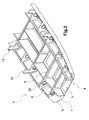
Figure 2 shows a perspective view of a subfloor structure of the helicopter ofFigure 1 , -
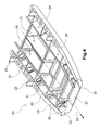
Figure 3 shows a further perspective view of the subfloor structure of the helicopter ofFigure 1 , -
Figure 4 shows a perspective view of a subfloor structure according to the invention, -
Figure 5 shows a further perspective view of the subfloor structure according to the invention, -
Figure 6 shows an exploded perspective view of the subfloor structure according to the invention, -
Figure 7 shows a perspective view of a part of the subfloor structure according to the invention, -
Figure 8 shows a further perspective view of the part of the subfloor structure ofFigure 7 , and -
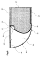
Figure 9 shows a cross sectional view of the part of the subfloor structure ofFigure 8 . - According to
Figure 1 ageneric helicopter 1 comprises anairframe 2 and asubfloor group 3 with alongitudinal axis 33. Thesubfloor group 3 is allocated within a lower part of theairframe 2 between acabin floor level 30 and anouter loft 31 of thehelicopter 1. - According to
Figure 2 corresponding features are referred to with the references ofFigure 1 . A state-of-the-art subfloor group 3 is essentially symmetrical with regard to thelongitudinal axis 33. Saidsubfloor group 3 is composed of abottom shell 4 with an essentially flat or smoothly curvedbottom shell portion 5 and two lateral curvedside shell portions 6, integrated essentially longitudinally along said flatbottom shell portion 5. Saidsubfloor group 3 further comprises essentially symmetrical with regard to the longitudinal axis 33 aframework 7,main frames 11 andfloor panels 13. Theframework 7 is built oflongerons 8, basically extending longitudinally all along thesubfloor group 3. Theframework 7 is further built ofcentral ribs 9 andlateral ribs 10, both being basically arranged orthogonally to thelongerons 8, and usually being coincident in their longitudinal position. The central andlateral ribs floor panels 13. Seat rails 14 are arranged within thefloor panels 13, their position being coincident with the longitudinal support beams 8. Thelongerons 8 intersect with theribs main frames 11, hence leading to numerouscruciform intersections 32. A highly loaded area represents the intersection of themain frames 11 and the longitudinal support beams 8. Here, either themain frame 11 or thelongitudinal support beams 8 have to be interrupted which results to a highly loaded joint. Thelongitudinal support beams 8 and thecentral ribs 9 and theframes 11 delimit the tank area in whichfuel tank bladders 12 are housed, being hence laterally and longitudinally supported by thelongitudinal support beams 8 and central ribs 9' ormain frames 11 respectively. Volumes between thelongitudinal support beams 8 and the lateral curvedside shell portions 6 are respectively used for systems integration. -
Figure 3 shows thesubfloor group 3 ofFig. 2 without thetank bladders 12 and thefloor panels 13 but with the orthogonal grid construction of the framework. - According to
Figure 4 corresponding features are referred to with the references ofFigures 1-3 . Anintegral subfloor structure 15 comprises a main load carrying bottomintegral shell 16 with an essentiallyflat shell portion 17 and twolateral shell portions 18, i.e. one of said twolateral shell portions 18 on each of both longitudinal sides of theflat shell portion 17. Continuous single-part ribs 20 andmain frames 23 are arranged orthogonally to thelongitudinal axis 33 of the aircraft. Theribs 20 are arranged orthogonally or slanted (not shown) with respect to thefloor panels 13. The twolateral shell portions 18 extend integrally from saidflat shell portion 17 along its longitudinally oriented sides and said twolateral shell portions 18 are curved towards respective lateral borders/lateral caps of saidribs 20 andmain frames 23. - For stabilization purposes longitudinally extending
end panels 19 are arranged at top ends of thelateral shell portions 18 essentially in the horizontal plane of thefloor panels 13. Eachend panel 19 is integral or riveted respectively with one of the twolateral shell portions 18 and is pointing towards an inside of thesubfloor structure 15. - Longitudinal support beams 21 are attached to the lower side of the
floor panels 13 and withfront flanges 34 orthogonally to theribs 20 and/ormain frames 23. Thefront flanges 34 are oriented from thefloor panels 13 towards thebottom shell 16. Alternatively, the longitudinal support beams 21 can be continuous, going through the rib's webs through cut-outs (not shown) and being attached to theribs 20 by means of additional clips and/or brackets (not shown). - The height of the longitudinal support beams 21 is a fraction of the distance between the
floor panels 13 and thebottom shell 16, i.e. the total subfloor height. Along at least 2/3 of the longitudinal extension of the longitudinal support beams 21 the height of the longitudinal support beams 21 is 2 to 20 times smaller than any distances between any of thefloor panels 13 and thebottom shell 16. - Essentially longitudinally extending
membrane elements 24 are attached between the longitudinal support beams 21 and thebottom shell 16. The twolateral shell portions 18 provide afree volume 29 with said longitudinally extendingmembrane elements 24 on each of both longitudinal sides of thesubfloor structure 15. - According to
Figure 5 corresponding features are referred to with the references ofFigures 1-4 . Theintegral subfloor structure 15 comprises thetank bladders 12 allocated between themain frames 23 and/orribs 20 and themembrane elements 24. - According to
Figure 6 corresponding features are referred to with the references ofFigures 1-5 . Theintegral subfloor structure 15 allows a bulgy shape of themembrane elements 24, as well as the continuity of theribs 20 and the main frames 23. - According to
Figure 7 corresponding features are referred to with the references ofFigures 1-6 . Themembrane elements 24 are attached at their upperlongitudinal hem 27 to the longitudinal support beams 21 and at their lowerlongitudinal hem 28 to theintegral bottom shell 16. Thelongitudinal support beam 21 and the floor panels (not shown) react the membrane loads of themembrane elements 24 at theirupper hems 27 and distribute them to the adjacentmain frames 23 orribs 20. The membrane loads at thelower membrane hem 28 are tangentially introduced to thebottom shell 16. The curved ends 26 of themembrane element 24 are not coupled to the adjacentmain frame 23 orrib 20, in order to ensure a purely two dimensional stress state of themembrane element 24. - Additional intermediate
lateral ribs 22 are used mainly as to support theend panels 19, the lateralcurved shell portions 18 and the longitudinal support beams 21. A flattank separation web 25 is provided to separate the tank volume between two longitudinal support beams 21 in two individual compartments. - According to
Figure 8 corresponding features are referred to with the references ofFigures 1-7 .Tank bladders 12 are implemented in theintegral subfloor structure 15. - According to
Figure 9 corresponding features are referred to with the references ofFigures 1-10 . The tank compartment of theintegral subfloor structure 15 is confined by thefloor panel 13, thebottom shell 16 and laterally by themembrane element 24. Thetank bladder 12 rests on theflat shell portion 17 and on themembrane element 24. Theupper membrane hem 27 is attached to thelongitudinal support beam 21 and to thefloor panel 13. Thelower membrane hem 28 is attached to thebottom shell 16. The cross section of the longitudinal support beam may have closed profile sections. - Seat rails 14 on the
floor panels 13 are allocated coincident to the longitudinal support beams 21, and integrated to the longitudinal support beams 21 in order to increase their moment of inertia. Thefree volume 29 enclosed by themembrane element 24, the lateralcurved shell portion 18 and thefloor panel 13 is preferably used for systems integration. -
- 1. Helicopter
- 2. Airframe
- 3. Subfloor group
- 4. Bottom Shell
- 5. Flat bottom shell portion
- 6. Lateral curved side shell portion
- 7. Framework
- 8. Longerons
- 9. Central rib
- 10. Lateral rib
- 11. Main frame
- 12. Fuel tank bladder
- 13. Floor panel
- 14. Seat rail
- 15. Integral subfloor group
- 16. Bottom Integral shell
- 17. Flat shell portion of the integral shell
- 18. Lateral curved shell portion of the integral shell
- 19. End panels
- 20. Rib
- 21. Longitudinal support beams
- 22. Intermediate lateral rib
- 23. Continuous main frame
- 24. Membrane
- 25. Tank separation web
- 26. Membrane curved end
- 27. Upper longitudinal membrane end
- 28. Lower longitudinal membrane end
- 29. Lateral systems integration volume
- 30. Floor plane
- 31. Outer aircraft loft
- 32. Cruciform intersection
- 33. Longitudinal axis
- 34. Front flanges
Claims (13)
- A helicopter airframe (2) with a longitudinal axis comprising:a subfloor structure (15) for supporting cabin floor panels (13) and/or at least one fuel tank bladder (12), said subfloor structure (15) having a bottom shell (16), ribs (20), main frames (23) and floor panels (13), said ribs (20) and main frames (23) extending essentially in planes perpendicular to said longitudinal axis on one side of the bottom shell (16) and the floor panels (13) being in an essentially horizontal plane essentially parallel to the longitudinal axis on the same side of the bottom shell (16) as the ribs (20) and main frames (23) and mounted on flat top edges of the ribs (20) and main frames (23) opposite to the bottom shell (16),the bottom shell (16) having an essentially flat shell portion (17) and two curved lateral shell portions (18) extending integrally from said flat shell portion (17) along its longitudinally oriented sides and being curved towards respective lateral borders of said ribs (20) and main frames (23), wherein longitudinal support beams (21) are provided with attachments for the floor panels (13), the longitudinal support beams (21) being attached at least partially to the ribs (20) and/or the main frames (23) and featuring along at least 2/3 of their longitudinal extension a height 2 to 20 times smaller than any distances of any of the floor panels (13) to the bottom shell (16).
- The helicopter airframe (2) according to claim 1, wherein at least one membrane element (24) is provided with an upper longitudinal hem (27) attached to said longitudinal support beams (21) and a lower longitudinal hem (28) attached to the bottom shell (16).
- The helicopter airframe (2) according to claim 2, wherein the at least one membrane element (24) laterally extends beyond the upper longitudinal hem (27) and its lower longitudinal hem (28) into the free volume (29).
- The helicopter airframe (2) according to claim 2, wherein the membrane element (24) is made of a flexible or semi-rigid material, such as fabric, cloth, mesh, plastic, fibre reinforced plastic, featuring a thickness of 0.1 mm to 3mm
- The helicopter airframe (2) according to claim 1, wherein the planes of the ribs (20) and/or the main frames (23) extending essentially perpendicular to said longitudinal support beams (21) are orthogonal or slanted with regard to the essentially horizontal plane of the floor panels (13).
- The helicopter airframe (2) according to claim 1, wherein end panels (19) are provided in the essentially horizontal plane of the floor panels (13) essentially longitudinally along a top end of the two lateral shell portions (18).
- The helicopter airframe (2) according to claim 6, each end panel (19) being integral respectively with one of the two lateral shell portions (18) and pointing towards an inside.
- The helicopter airframe (2) according to claim 1, wherein longerons are provided, said longerons being functionally and physically integrated within said curved lateral shell portions (18) of the bottom shell (16) without any interruptions.
- The helicopter airframe (2) according to claim 1, wherein the ribs (20) are continuous and extend from the flat shell portion of the bottom shell (17) to the floor panels (13) and laterally enclose the whole width of the bottom shell (16) being attached to their lateral curved shell portions (18).
- The helicopter airframe (2) according to claim 1, wherein the main frames (23) are continuous and extend from the flat shell portion of the bottom shell (17) to the floor panels (13) and laterally enclose the whole width of the bottom shell (16) being attached to their lateral curved shell portions (18).
- The helicopter airframe (2) according to claim 1, wherein intermediate lateral ribs (22) are provided supporting the end panels (19), the lateral curved shell portions (18) and/or the longitudinal support beams (21).
- The helicopter airframe (2) according to claim 1, wherein at least one flat tank separation web (25) is provided extending from the flat shell portion of the bottom shell (17) to the floor panels (13) and longitudinally between the ribs (20) and/or the main frames (23).
- The helicopter airframe (2) according to claim 1, wherein seat rails (14) are provided allocated coincident to the longitudinal support beams (21) and preferably integrated to the longitudinal beams (21).
Priority Applications (2)
| Application Number | Priority Date | Filing Date | Title |
|---|---|---|---|
| EP13400030.6A EP2876042B1 (en) | 2013-11-20 | 2013-11-20 | Helicopter airframe |
| US14/546,325 US9517831B2 (en) | 2013-11-20 | 2014-11-18 | Rotary wing aircraft airframe |
Applications Claiming Priority (1)
| Application Number | Priority Date | Filing Date | Title |
|---|---|---|---|
| EP13400030.6A EP2876042B1 (en) | 2013-11-20 | 2013-11-20 | Helicopter airframe |
Publications (2)
| Publication Number | Publication Date |
|---|---|
| EP2876042A1 true EP2876042A1 (en) | 2015-05-27 |
| EP2876042B1 EP2876042B1 (en) | 2018-01-03 |
Family
ID=50156524
Family Applications (1)
| Application Number | Title | Priority Date | Filing Date |
|---|---|---|---|
| EP13400030.6A Not-in-force EP2876042B1 (en) | 2013-11-20 | 2013-11-20 | Helicopter airframe |
Country Status (2)
| Country | Link |
|---|---|
| US (1) | US9517831B2 (en) |
| EP (1) | EP2876042B1 (en) |
Families Citing this family (11)
| Publication number | Priority date | Publication date | Assignee | Title |
|---|---|---|---|---|
| CH710657A1 (en) * | 2015-01-28 | 2016-07-29 | Marenco Swisshelicopter Ag | Helicopter cabin. |
| EP3333064B1 (en) * | 2016-12-07 | 2020-04-22 | AIRBUS HELICOPTERS DEUTSCHLAND GmbH | An aircraft with an airframe and at least one electrically powered thrust producing unit |
| EP3584151B1 (en) | 2018-06-20 | 2021-01-27 | AIRBUS HELICOPTERS DEUTSCHLAND GmbH | A modular subfloor arrangement for an aircraft |
| IL260172B (en) * | 2018-06-20 | 2021-10-31 | Israel Aerospace Ind Ltd | Floor system for anaircraft |
| CN112407304B (en) * | 2020-09-30 | 2021-07-02 | 北京北航天宇长鹰无人机科技有限公司 | A drone fuel tank |
| US12312064B2 (en) * | 2021-09-24 | 2025-05-27 | Textron Innovations Inc. | Shaped aircraft fuel cells, systems and methods for enhanced crashworthiness |
| EP4603392A3 (en) * | 2022-07-19 | 2025-09-24 | AIRBUS HELICOPTERS DEUTSCHLAND GmbH | A rotorcraft with an energy source storage unit |
| CN115743646B (en) * | 2022-11-25 | 2025-07-04 | 北京中航智科技有限公司 | An integrated unmanned helicopter main body |
| KR20240096158A (en) * | 2022-12-19 | 2024-06-26 | 현대자동차주식회사 | Dispersion Structure for Impact |
| KR20240139825A (en) * | 2023-03-15 | 2024-09-24 | 현대자동차주식회사 | Collision load distribution structure of the fuselage |
| EP4574648A1 (en) * | 2023-12-22 | 2025-06-25 | Airbus Operations, S.L.U. | An aircraft fuselage section |
Citations (5)
| Publication number | Priority date | Publication date | Assignee | Title |
|---|---|---|---|---|
| US3652050A (en) * | 1970-02-05 | 1972-03-28 | Fairchild Industries | Vehicle seat mounting system |
| DE3049429A1 (en) * | 1980-12-30 | 1982-07-22 | Messerschmitt Boelkow Blohm | Crash protection esp. for helicopter fuel tank - absorbs energy esp. by deformation of solids and displacement of fluid esp. fuel in deforming tank |
| US6427945B1 (en) | 1999-05-14 | 2002-08-06 | Eurocopter Deutschland Gmbh | Subfloor structure of an aircraft airframe |
| US6959894B2 (en) | 2002-12-04 | 2005-11-01 | Kawasaki Jukogyo Kabushiki Kaisha | Impact resistant structure for the helicopter and energy absorber used for the same |
| EP2455285A1 (en) * | 2009-07-17 | 2012-05-23 | Mitsubishi Heavy Industries, Ltd. | Shock absorbing structure |
Family Cites Families (5)
| Publication number | Priority date | Publication date | Assignee | Title |
|---|---|---|---|---|
| US6554225B1 (en) * | 2002-06-14 | 2003-04-29 | The Boeing Company | Commercial aircraft low cost, lightweight floor design |
| FR2877916B1 (en) * | 2004-11-15 | 2008-04-25 | Airbus France Sas | AIRCRAFT FUSELAGE STRUCTURE FRAME |
| EP1777155B1 (en) * | 2005-10-21 | 2008-12-10 | Agusta S.p.A. | Deformable floor substructure for a helicopter |
| FR2896770B1 (en) * | 2006-01-27 | 2008-04-11 | Eurocopter France | SIDE-HOLDING ANTI-CRASH COMPOSITE STRUCTURE FOR AIRCRAFT. |
| US8336820B2 (en) * | 2008-10-27 | 2012-12-25 | Embraer S.A. | Aircraft cabin floor structures, systems and methods |
-
2013
- 2013-11-20 EP EP13400030.6A patent/EP2876042B1/en not_active Not-in-force
-
2014
- 2014-11-18 US US14/546,325 patent/US9517831B2/en not_active Expired - Fee Related
Patent Citations (5)
| Publication number | Priority date | Publication date | Assignee | Title |
|---|---|---|---|---|
| US3652050A (en) * | 1970-02-05 | 1972-03-28 | Fairchild Industries | Vehicle seat mounting system |
| DE3049429A1 (en) * | 1980-12-30 | 1982-07-22 | Messerschmitt Boelkow Blohm | Crash protection esp. for helicopter fuel tank - absorbs energy esp. by deformation of solids and displacement of fluid esp. fuel in deforming tank |
| US6427945B1 (en) | 1999-05-14 | 2002-08-06 | Eurocopter Deutschland Gmbh | Subfloor structure of an aircraft airframe |
| US6959894B2 (en) | 2002-12-04 | 2005-11-01 | Kawasaki Jukogyo Kabushiki Kaisha | Impact resistant structure for the helicopter and energy absorber used for the same |
| EP2455285A1 (en) * | 2009-07-17 | 2012-05-23 | Mitsubishi Heavy Industries, Ltd. | Shock absorbing structure |
Non-Patent Citations (1)
| Title |
|---|
| "COMPOSITES SOFTEN IMPACT", FLIGHT INTERNATIONAL, REED BUSINESS INFORMATION, SUTTON SURREY, GB, vol. 167, no. 4982, 26 April 2005 (2005-04-26), pages 26, XP001227208, ISSN: 0015-3710 * |
Also Published As
| Publication number | Publication date |
|---|---|
| US20150136906A1 (en) | 2015-05-21 |
| US9517831B2 (en) | 2016-12-13 |
| EP2876042B1 (en) | 2018-01-03 |
Similar Documents
| Publication | Publication Date | Title |
|---|---|---|
| EP2876042B1 (en) | Helicopter airframe | |
| CN101952166B (en) | Structural component with rib and cross member element | |
| EP2018316B1 (en) | Floor structure for a fuselage | |
| US9688381B2 (en) | Subfloor structure with an integral hull for a rotary wing aircraft | |
| US20080093503A1 (en) | Structural frame for an aircraft fuselage | |
| KR102073995B1 (en) | Apparatus and methods for joining composite structures of aircrafts | |
| EP2027012B1 (en) | Tail structure for an aircraft or spacecraft | |
| US6427945B1 (en) | Subfloor structure of an aircraft airframe | |
| CN105730673B (en) | Landing gear bay roof of improved design | |
| CN103158854B (en) | Aircraft nose structure | |
| US8047465B2 (en) | Composite anti-crash structure with lateral retention, for an aircraft | |
| RU2667657C2 (en) | Airfoil, aircraft and method for manufacture thereof | |
| CN101977811B (en) | Fuselage structure for aircraft | |
| US20100163669A1 (en) | Super aircraft structrue | |
| CN105730671B (en) | Aircraft rear structure | |
| JP2010516536A (en) | CRP / metal composite aircraft or spacecraft fuselage with metal framework | |
| US7475850B2 (en) | Cockpit floor for aircraft | |
| CN103857591B (en) | Improved front landing-gear well | |
| US9090331B2 (en) | Aircraft floor support strut with design failure point | |
| EP4606695A1 (en) | Aircraft and fuselage with energy absorbing structure | |
| EP3498591A1 (en) | A composite truss beam with a sandwich web | |
| CN105905272B (en) | Flat-folded rear pressure bulkhead | |
| RU2391251C2 (en) | Aircraft airframe | |
| EP4656512A1 (en) | Aircraft fuselage and aircraft or spacecraft |
Legal Events
| Date | Code | Title | Description |
|---|---|---|---|
| PUAI | Public reference made under article 153(3) epc to a published international application that has entered the european phase |
Free format text: ORIGINAL CODE: 0009012 |
|
| 17P | Request for examination filed |
Effective date: 20131120 |
|
| AK | Designated contracting states |
Kind code of ref document: A1 Designated state(s): AL AT BE BG CH CY CZ DE DK EE ES FI FR GB GR HR HU IE IS IT LI LT LU LV MC MK MT NL NO PL PT RO RS SE SI SK SM TR |
|
| AX | Request for extension of the european patent |
Extension state: BA ME |
|
| R17P | Request for examination filed (corrected) |
Effective date: 20150609 |
|
| RBV | Designated contracting states (corrected) |
Designated state(s): AL AT BE BG CH CY CZ DE DK EE ES FI FR GB GR HR HU IE IS IT LI LT LU LV MC MK MT NL NO PL PT RO RS SE SI SK SM TR |
|
| 17Q | First examination report despatched |
Effective date: 20170207 |
|
| GRAP | Despatch of communication of intention to grant a patent |
Free format text: ORIGINAL CODE: EPIDOSNIGR1 |
|
| INTG | Intention to grant announced |
Effective date: 20170920 |
|
| GRAS | Grant fee paid |
Free format text: ORIGINAL CODE: EPIDOSNIGR3 |
|
| GRAA | (expected) grant |
Free format text: ORIGINAL CODE: 0009210 |
|
| AK | Designated contracting states |
Kind code of ref document: B1 Designated state(s): AL AT BE BG CH CY CZ DE DK EE ES FI FR GB GR HR HU IE IS IT LI LT LU LV MC MK MT NL NO PL PT RO RS SE SI SK SM TR |
|
| REG | Reference to a national code |
Ref country code: GB Ref legal event code: FG4D |
|
| REG | Reference to a national code |
Ref country code: CH Ref legal event code: EP Ref country code: AT Ref legal event code: REF Ref document number: 959988 Country of ref document: AT Kind code of ref document: T Effective date: 20180115 |
|
| REG | Reference to a national code |
Ref country code: IE Ref legal event code: FG4D |
|
| REG | Reference to a national code |
Ref country code: DE Ref legal event code: R096 Ref document number: 602013031591 Country of ref document: DE |
|
| REG | Reference to a national code |
Ref country code: NL Ref legal event code: MP Effective date: 20180103 |
|
| REG | Reference to a national code |
Ref country code: LT Ref legal event code: MG4D |
|
| REG | Reference to a national code |
Ref country code: AT Ref legal event code: MK05 Ref document number: 959988 Country of ref document: AT Kind code of ref document: T Effective date: 20180103 |
|
| PG25 | Lapsed in a contracting state [announced via postgrant information from national office to epo] |
Ref country code: NL Free format text: LAPSE BECAUSE OF FAILURE TO SUBMIT A TRANSLATION OF THE DESCRIPTION OR TO PAY THE FEE WITHIN THE PRESCRIBED TIME-LIMIT Effective date: 20180103 |
|
| PG25 | Lapsed in a contracting state [announced via postgrant information from national office to epo] |
Ref country code: ES Free format text: LAPSE BECAUSE OF FAILURE TO SUBMIT A TRANSLATION OF THE DESCRIPTION OR TO PAY THE FEE WITHIN THE PRESCRIBED TIME-LIMIT Effective date: 20180103 Ref country code: HR Free format text: LAPSE BECAUSE OF FAILURE TO SUBMIT A TRANSLATION OF THE DESCRIPTION OR TO PAY THE FEE WITHIN THE PRESCRIBED TIME-LIMIT Effective date: 20180103 Ref country code: NO Free format text: LAPSE BECAUSE OF FAILURE TO SUBMIT A TRANSLATION OF THE DESCRIPTION OR TO PAY THE FEE WITHIN THE PRESCRIBED TIME-LIMIT Effective date: 20180403 Ref country code: FI Free format text: LAPSE BECAUSE OF FAILURE TO SUBMIT A TRANSLATION OF THE DESCRIPTION OR TO PAY THE FEE WITHIN THE PRESCRIBED TIME-LIMIT Effective date: 20180103 Ref country code: LT Free format text: LAPSE BECAUSE OF FAILURE TO SUBMIT A TRANSLATION OF THE DESCRIPTION OR TO PAY THE FEE WITHIN THE PRESCRIBED TIME-LIMIT Effective date: 20180103 Ref country code: CY Free format text: LAPSE BECAUSE OF FAILURE TO SUBMIT A TRANSLATION OF THE DESCRIPTION OR TO PAY THE FEE WITHIN THE PRESCRIBED TIME-LIMIT Effective date: 20180103 |
|
| PG25 | Lapsed in a contracting state [announced via postgrant information from national office to epo] |
Ref country code: LV Free format text: LAPSE BECAUSE OF FAILURE TO SUBMIT A TRANSLATION OF THE DESCRIPTION OR TO PAY THE FEE WITHIN THE PRESCRIBED TIME-LIMIT Effective date: 20180103 Ref country code: GR Free format text: LAPSE BECAUSE OF FAILURE TO SUBMIT A TRANSLATION OF THE DESCRIPTION OR TO PAY THE FEE WITHIN THE PRESCRIBED TIME-LIMIT Effective date: 20180404 Ref country code: IS Free format text: LAPSE BECAUSE OF FAILURE TO SUBMIT A TRANSLATION OF THE DESCRIPTION OR TO PAY THE FEE WITHIN THE PRESCRIBED TIME-LIMIT Effective date: 20180503 Ref country code: SE Free format text: LAPSE BECAUSE OF FAILURE TO SUBMIT A TRANSLATION OF THE DESCRIPTION OR TO PAY THE FEE WITHIN THE PRESCRIBED TIME-LIMIT Effective date: 20180103 Ref country code: RS Free format text: LAPSE BECAUSE OF FAILURE TO SUBMIT A TRANSLATION OF THE DESCRIPTION OR TO PAY THE FEE WITHIN THE PRESCRIBED TIME-LIMIT Effective date: 20180103 Ref country code: PL Free format text: LAPSE BECAUSE OF FAILURE TO SUBMIT A TRANSLATION OF THE DESCRIPTION OR TO PAY THE FEE WITHIN THE PRESCRIBED TIME-LIMIT Effective date: 20180103 Ref country code: BG Free format text: LAPSE BECAUSE OF FAILURE TO SUBMIT A TRANSLATION OF THE DESCRIPTION OR TO PAY THE FEE WITHIN THE PRESCRIBED TIME-LIMIT Effective date: 20180403 Ref country code: AT Free format text: LAPSE BECAUSE OF FAILURE TO SUBMIT A TRANSLATION OF THE DESCRIPTION OR TO PAY THE FEE WITHIN THE PRESCRIBED TIME-LIMIT Effective date: 20180103 |
|
| REG | Reference to a national code |
Ref country code: DE Ref legal event code: R097 Ref document number: 602013031591 Country of ref document: DE |
|
| PG25 | Lapsed in a contracting state [announced via postgrant information from national office to epo] |
Ref country code: RO Free format text: LAPSE BECAUSE OF FAILURE TO SUBMIT A TRANSLATION OF THE DESCRIPTION OR TO PAY THE FEE WITHIN THE PRESCRIBED TIME-LIMIT Effective date: 20180103 Ref country code: EE Free format text: LAPSE BECAUSE OF FAILURE TO SUBMIT A TRANSLATION OF THE DESCRIPTION OR TO PAY THE FEE WITHIN THE PRESCRIBED TIME-LIMIT Effective date: 20180103 Ref country code: AL Free format text: LAPSE BECAUSE OF FAILURE TO SUBMIT A TRANSLATION OF THE DESCRIPTION OR TO PAY THE FEE WITHIN THE PRESCRIBED TIME-LIMIT Effective date: 20180103 |
|
| PLBE | No opposition filed within time limit |
Free format text: ORIGINAL CODE: 0009261 |
|
| STAA | Information on the status of an ep patent application or granted ep patent |
Free format text: STATUS: NO OPPOSITION FILED WITHIN TIME LIMIT |
|
| PG25 | Lapsed in a contracting state [announced via postgrant information from national office to epo] |
Ref country code: DK Free format text: LAPSE BECAUSE OF FAILURE TO SUBMIT A TRANSLATION OF THE DESCRIPTION OR TO PAY THE FEE WITHIN THE PRESCRIBED TIME-LIMIT Effective date: 20180103 Ref country code: CZ Free format text: LAPSE BECAUSE OF FAILURE TO SUBMIT A TRANSLATION OF THE DESCRIPTION OR TO PAY THE FEE WITHIN THE PRESCRIBED TIME-LIMIT Effective date: 20180103 Ref country code: SK Free format text: LAPSE BECAUSE OF FAILURE TO SUBMIT A TRANSLATION OF THE DESCRIPTION OR TO PAY THE FEE WITHIN THE PRESCRIBED TIME-LIMIT Effective date: 20180103 Ref country code: SM Free format text: LAPSE BECAUSE OF FAILURE TO SUBMIT A TRANSLATION OF THE DESCRIPTION OR TO PAY THE FEE WITHIN THE PRESCRIBED TIME-LIMIT Effective date: 20180103 |
|
| 26N | No opposition filed |
Effective date: 20181005 |
|
| PG25 | Lapsed in a contracting state [announced via postgrant information from national office to epo] |
Ref country code: SI Free format text: LAPSE BECAUSE OF FAILURE TO SUBMIT A TRANSLATION OF THE DESCRIPTION OR TO PAY THE FEE WITHIN THE PRESCRIBED TIME-LIMIT Effective date: 20180103 |
|
| REG | Reference to a national code |
Ref country code: CH Ref legal event code: PL |
|
| PG25 | Lapsed in a contracting state [announced via postgrant information from national office to epo] |
Ref country code: MC Free format text: LAPSE BECAUSE OF FAILURE TO SUBMIT A TRANSLATION OF THE DESCRIPTION OR TO PAY THE FEE WITHIN THE PRESCRIBED TIME-LIMIT Effective date: 20180103 Ref country code: LU Free format text: LAPSE BECAUSE OF NON-PAYMENT OF DUE FEES Effective date: 20181120 |
|
| REG | Reference to a national code |
Ref country code: BE Ref legal event code: MM Effective date: 20181130 |
|
| REG | Reference to a national code |
Ref country code: IE Ref legal event code: MM4A |
|
| PG25 | Lapsed in a contracting state [announced via postgrant information from national office to epo] |
Ref country code: LI Free format text: LAPSE BECAUSE OF NON-PAYMENT OF DUE FEES Effective date: 20181130 Ref country code: CH Free format text: LAPSE BECAUSE OF NON-PAYMENT OF DUE FEES Effective date: 20181130 |
|
| PG25 | Lapsed in a contracting state [announced via postgrant information from national office to epo] |
Ref country code: IE Free format text: LAPSE BECAUSE OF NON-PAYMENT OF DUE FEES Effective date: 20181120 |
|
| PG25 | Lapsed in a contracting state [announced via postgrant information from national office to epo] |
Ref country code: BE Free format text: LAPSE BECAUSE OF NON-PAYMENT OF DUE FEES Effective date: 20181130 |
|
| PG25 | Lapsed in a contracting state [announced via postgrant information from national office to epo] |
Ref country code: MT Free format text: LAPSE BECAUSE OF NON-PAYMENT OF DUE FEES Effective date: 20181120 |
|
| PG25 | Lapsed in a contracting state [announced via postgrant information from national office to epo] |
Ref country code: TR Free format text: LAPSE BECAUSE OF FAILURE TO SUBMIT A TRANSLATION OF THE DESCRIPTION OR TO PAY THE FEE WITHIN THE PRESCRIBED TIME-LIMIT Effective date: 20180103 |
|
| PG25 | Lapsed in a contracting state [announced via postgrant information from national office to epo] |
Ref country code: PT Free format text: LAPSE BECAUSE OF FAILURE TO SUBMIT A TRANSLATION OF THE DESCRIPTION OR TO PAY THE FEE WITHIN THE PRESCRIBED TIME-LIMIT Effective date: 20180103 |
|
| PG25 | Lapsed in a contracting state [announced via postgrant information from national office to epo] |
Ref country code: HU Free format text: LAPSE BECAUSE OF FAILURE TO SUBMIT A TRANSLATION OF THE DESCRIPTION OR TO PAY THE FEE WITHIN THE PRESCRIBED TIME-LIMIT; INVALID AB INITIO Effective date: 20131120 Ref country code: MK Free format text: LAPSE BECAUSE OF NON-PAYMENT OF DUE FEES Effective date: 20180103 |
|
| PGFP | Annual fee paid to national office [announced via postgrant information from national office to epo] |
Ref country code: GB Payment date: 20211119 Year of fee payment: 9 |
|
| PGFP | Annual fee paid to national office [announced via postgrant information from national office to epo] |
Ref country code: IT Payment date: 20221124 Year of fee payment: 10 Ref country code: FR Payment date: 20221129 Year of fee payment: 10 Ref country code: DE Payment date: 20221123 Year of fee payment: 10 |
|
| P01 | Opt-out of the competence of the unified patent court (upc) registered |
Effective date: 20230530 |
|
| GBPC | Gb: european patent ceased through non-payment of renewal fee |
Effective date: 20221120 |
|
| PG25 | Lapsed in a contracting state [announced via postgrant information from national office to epo] |
Ref country code: GB Free format text: LAPSE BECAUSE OF NON-PAYMENT OF DUE FEES Effective date: 20221120 |
|
| REG | Reference to a national code |
Ref country code: DE Ref legal event code: R119 Ref document number: 602013031591 Country of ref document: DE |
|
| PG25 | Lapsed in a contracting state [announced via postgrant information from national office to epo] |
Ref country code: DE Free format text: LAPSE BECAUSE OF NON-PAYMENT OF DUE FEES Effective date: 20240601 |
|
| PG25 | Lapsed in a contracting state [announced via postgrant information from national office to epo] |
Ref country code: FR Free format text: LAPSE BECAUSE OF NON-PAYMENT OF DUE FEES Effective date: 20231130 |
|
| PG25 | Lapsed in a contracting state [announced via postgrant information from national office to epo] |
Ref country code: FR Free format text: LAPSE BECAUSE OF NON-PAYMENT OF DUE FEES Effective date: 20231130 Ref country code: DE Free format text: LAPSE BECAUSE OF NON-PAYMENT OF DUE FEES Effective date: 20240601 |
|
| PG25 | Lapsed in a contracting state [announced via postgrant information from national office to epo] |
Ref country code: IT Free format text: LAPSE BECAUSE OF NON-PAYMENT OF DUE FEES Effective date: 20231120 |
|
| PG25 | Lapsed in a contracting state [announced via postgrant information from national office to epo] |
Ref country code: IT Free format text: LAPSE BECAUSE OF NON-PAYMENT OF DUE FEES Effective date: 20231120 |