EP2875957A1 - Multibeam light source unit, method of adjusting the same, light scanning unit, and electrophotography type image forming apparatus - Google Patents
Multibeam light source unit, method of adjusting the same, light scanning unit, and electrophotography type image forming apparatus Download PDFInfo
- Publication number
- EP2875957A1 EP2875957A1 EP14189097.0A EP14189097A EP2875957A1 EP 2875957 A1 EP2875957 A1 EP 2875957A1 EP 14189097 A EP14189097 A EP 14189097A EP 2875957 A1 EP2875957 A1 EP 2875957A1
- Authority
- EP
- European Patent Office
- Prior art keywords
- light source
- unit
- multibeam
- holder
- flange
- Prior art date
- Legal status (The legal status is an assumption and is not a legal conclusion. Google has not performed a legal analysis and makes no representation as to the accuracy of the status listed.)
- Granted
Links
Images







Classifications
-
- G—PHYSICS
- G03—PHOTOGRAPHY; CINEMATOGRAPHY; ANALOGOUS TECHNIQUES USING WAVES OTHER THAN OPTICAL WAVES; ELECTROGRAPHY; HOLOGRAPHY
- G03G—ELECTROGRAPHY; ELECTROPHOTOGRAPHY; MAGNETOGRAPHY
- G03G15/00—Apparatus for electrographic processes using a charge pattern
- G03G15/04—Apparatus for electrographic processes using a charge pattern for exposing, i.e. imagewise exposure by optically projecting the original image on a photoconductive recording material
-
- B—PERFORMING OPERATIONS; TRANSPORTING
- B41—PRINTING; LINING MACHINES; TYPEWRITERS; STAMPS
- B41J—TYPEWRITERS; SELECTIVE PRINTING MECHANISMS, i.e. MECHANISMS PRINTING OTHERWISE THAN FROM A FORME; CORRECTION OF TYPOGRAPHICAL ERRORS
- B41J2/00—Typewriters or selective printing mechanisms characterised by the printing or marking process for which they are designed
- B41J2/435—Typewriters or selective printing mechanisms characterised by the printing or marking process for which they are designed characterised by selective application of radiation to a printing material or impression-transfer material
- B41J2/47—Typewriters or selective printing mechanisms characterised by the printing or marking process for which they are designed characterised by selective application of radiation to a printing material or impression-transfer material using the combination of scanning and modulation of light
- B41J2/471—Typewriters or selective printing mechanisms characterised by the printing or marking process for which they are designed characterised by selective application of radiation to a printing material or impression-transfer material using the combination of scanning and modulation of light using dot sequential main scanning by means of a light deflector, e.g. a rotating polygonal mirror
- B41J2/473—Typewriters or selective printing mechanisms characterised by the printing or marking process for which they are designed characterised by selective application of radiation to a printing material or impression-transfer material using the combination of scanning and modulation of light using dot sequential main scanning by means of a light deflector, e.g. a rotating polygonal mirror using multiple light beams, wavelengths or colours
-
- F—MECHANICAL ENGINEERING; LIGHTING; HEATING; WEAPONS; BLASTING
- F21—LIGHTING
- F21V—FUNCTIONAL FEATURES OR DETAILS OF LIGHTING DEVICES OR SYSTEMS THEREOF; STRUCTURAL COMBINATIONS OF LIGHTING DEVICES WITH OTHER ARTICLES, NOT OTHERWISE PROVIDED FOR
- F21V14/00—Controlling the distribution of the light emitted by adjustment of elements
- F21V14/02—Controlling the distribution of the light emitted by adjustment of elements by movement of light sources
-
- F—MECHANICAL ENGINEERING; LIGHTING; HEATING; WEAPONS; BLASTING
- F21—LIGHTING
- F21V—FUNCTIONAL FEATURES OR DETAILS OF LIGHTING DEVICES OR SYSTEMS THEREOF; STRUCTURAL COMBINATIONS OF LIGHTING DEVICES WITH OTHER ARTICLES, NOT OTHERWISE PROVIDED FOR
- F21V19/00—Fastening of light sources or lamp holders
- F21V19/02—Fastening of light sources or lamp holders with provision for adjustment, e.g. for focusing
-
- G—PHYSICS
- G02—OPTICS
- G02B—OPTICAL ELEMENTS, SYSTEMS OR APPARATUS
- G02B26/00—Optical devices or arrangements for the control of light using movable or deformable optical elements
- G02B26/08—Optical devices or arrangements for the control of light using movable or deformable optical elements for controlling the direction of light
- G02B26/0816—Optical devices or arrangements for the control of light using movable or deformable optical elements for controlling the direction of light by means of one or more reflecting elements
- G02B26/0833—Optical devices or arrangements for the control of light using movable or deformable optical elements for controlling the direction of light by means of one or more reflecting elements the reflecting element being a micromechanical device, e.g. a MEMS mirror, DMD
-
- Y—GENERAL TAGGING OF NEW TECHNOLOGICAL DEVELOPMENTS; GENERAL TAGGING OF CROSS-SECTIONAL TECHNOLOGIES SPANNING OVER SEVERAL SECTIONS OF THE IPC; TECHNICAL SUBJECTS COVERED BY FORMER USPC CROSS-REFERENCE ART COLLECTIONS [XRACs] AND DIGESTS
- Y10—TECHNICAL SUBJECTS COVERED BY FORMER USPC
- Y10T—TECHNICAL SUBJECTS COVERED BY FORMER US CLASSIFICATION
- Y10T29/00—Metal working
- Y10T29/49—Method of mechanical manufacture
- Y10T29/49002—Electrical device making
- Y10T29/49004—Electrical device making including measuring or testing of device or component part
Definitions
- One or more embodiments relate to a multibeam light source unit, a method of adjusting the unit, a light scanning unit, and an electrophotography type image forming apparatus, and more particularly, to a multibeam light source unit in which adjustment of light sources is easy in an assembly process, a method of adjusting the unit, a light scanning unit, and an electrophotography type image forming apparatus.
- An electrophotography type image forming apparatus such as a laser printer, a digital copying machine, and a multifunction printer (MFP)
- MFP multifunction printer
- An electrophotography type image forming apparatus has a structure in which by emitting a light beam to a photoreceptor through a light scanning device, an electrostatic latent image is formed, the formed electrostatic latent image is developed to a development image by using a developer such as a toner, and the development image is transferred on a printing medium.
- a multibeam light scanning unit which records a plurality of lines by using a plurality of light beams, may be used in order to improve the printing speed.
- a multibeam light scanning unit uses a light source, which emits at least two light beams (hereinafter, referred to as a multibeam), such as a multibeam laser diode.
- the light scanning unit has a plurality of light sources to be modulated by an image signal corresponding to image information of a plurality of single colors, for example, black (K), magenta (M), yellow (Y), cyan (C).
- a multibeam light scanning unit In a multibeam light scanning unit, adjustment of interval between beams of a multibeam may be performed by rotating light sources.
- a multibeam light scanning unit includes a light source 1 fixed to an optical housing 8 by using a light source holder 5.
- the light source holder 5 may be coupled with the optical housing 8 by using screws.
- Adjustment of intervals between beams of the light source 1 may be performed by pressing the light source 1 into the light source holder 5 and grabbing and turning a grip unit 5A of the light source holder 5.
- FIG. 1 As an example, as illustrated in FIG.
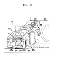
- an optical scanning unit has a structure in which an LD unit 40 is formed by pressing two laser diodes 54 and 55 into a holder 55 with a leaf spring 65 pressing the LD unit 40 into an installation hole of an optical housing 60. Adjustment of rotation of the LD unit 40 is performed by turning an adjustment screw 71 of an adjustment device maintenance unit 58.
- the sensitivity of the rotational angle of a light source may not matter.
- the angle tolerance of a light source using two beams may be, for example, approximately 14 degrees.
- the angle tolerance may be, for example, within 1.5 degrees and thus the sensitivity increases, for example, by 9.3 times or more.
- deterioration in the picture quality due to this problem may be small, but in a color image forming apparatus using a plurality of light sources with a plurality of photoreceptors, this causes incorrect image colors and thus degrades the quality of an image.
- a light scanning unit using a tilted incident beam may reduce the size and material cost of a light scanning unit having a plurality of mounted light sources because it has compact light path layout and smaller number of parts.
- a plurality of light sources may be disposed with narrow intervals.
- it is not easy to mount a plurality of light sources with narrow intervals because of issues of size, shape, and fixing method of light source holders that are used in the conventional assembly of light sources.
- One or more embodiments include a multibeam light source unit in which adjustment of light sources is easily performed and that has a compact structure, a method of adjusting the multibeam light source unit, a light scanning unit, and an electrophotography type image forming apparatus.
- a multibeam light source unit includes a plurality of light sources that emit multibeam, respectively, a flange that has an installation surface on which a plurality of holder installation holes are provided, and a plurality of middle holders on each of which a corresponding one of the plurality of light sources is provided, wherein each of the plurality of the middle holders includes a light source mounting unit on which one of the plurality of the light sources is provided, a cylinder-shape insertion unit that is inserted into one of the plurality of the holder installation holes, a first fixing protrusion unit and a second fixing protrusion unit, each of which is protruding outside from the light source mounting unit and is fixed to the flange by adhesive; and a jig coupling unit that is coupled with a jig when adjustment is performed.
- the plurality of holder installation holes may be disposed in rows and columns in a main scanning direction and in a sub scanning direction, respectively.
- the plurality of holder installation holes may be four holder installation holes, and the four holder installation holes may be disposed in two rows and two columns in a main scanning direction and in a sub scanning direction, respectively.
- the plurality of holder installation holes may be two holder installation holes and the two holder installation holes may be disposed with an interval in a sub scanning direction.
- the flange may include a first fixing groove unit and a second fixing groove unit concavely formed in the vicinity of each of the plurality of holder installation holes.
- the first and second fixing groove units may be formed by being extended in an arc shape centering around a corresponding one of the plurality of holder installation holes.
- the first and second fixing groove units may be formed at positions to be in contact with a first fixing protrusion unit and a second fixing protrusion unit, respectively, of the plurality of the middle holders.
- the plurality of holder installation holes and the first and second fixing groove units may be formed in bilateral symmetry or rotational symmetry on the installation surface of the flange.
- the flange may be formed of plastic resin.
- the light source mounting unit may include a penetration hole into which the light source is pressed in, and the penetration hole may penetrate to the end of the insertion unit.
- the outer circumference surface of the light source mounting unit may be formed in a canted column shape, and the canted column shape of the light source mounting unit may perform as a jig coupling unit.
- the first and second fixing protrusion units may be disposed in bilateral symmetry or rotational symmetry with respect to the light source mounting unit.
- part of the end may be removed or a penetration hole may be formed at the end.
- the plurality of middle holders may be fixed to the flange with photopolymer adhesive.
- Each of the first and second jig coupling units may have a protrusion shape protruding from circumference of the light source mounting unit.
- Each of the first and second jig coupling units may have a concave groove shape concavely formed in circumference of the light source mounting unit.
- the first and second jig coupling units may be disposed in bilateral symmetry or rotational symmetry with respect to the light source mounting unit.
- the first and second jig coupling units may have shapes different from each other.
- the plurality of middle holders may be made of metal or plastic resin.
- the multibeam light source unit may further include a circuit board that is provided on the installation surface of the flange, and drives and controls the plurality of light sources.
- the plurality of middle holders may be disposed between the flange and the circuit board.
- the flange may include a side wall disposed outside of the installation surface to provide a space that accommodates the plurality of middle holders, and the circuit board may be supported by the side wall.
- the plurality of light sources may be multibeam laser diodes.
- a method of adjusting a multibeam light source unit includes providing a light source on a light source mounting unit of a middle holder, with a jig of adjustment equipment holding a jig coupling unit of the middle holder, inserting the light source mounting unit of the middle holder into any one of a plurality of holder installation holes disposed on an installation surface of a flange, providing power to the light source through the jig, with detecting the position and interval of a multibeam emitted from the light source, adjusting at least one of the upward, downward, left, right and rotation directions of the middle holder so that the multibeam has a predetermined position and interval, and fixing to the flange by adhesive, a first fixing protrusion unit and a second fixing protrusion unit formed to protrude outside from the light source mounting unit of the middle holder.
- the operations may be repeated until all the light sources are provided to the plurality of holder installation holes of the flange.
- light sources may be provided to the same number of the plurality of middle holders as the number of the plurality of holder installation holes of the flange, and the other operations may be simultaneously performed for the plurality of middle holders.
- the jig may determine the direction of the middle holder according to the shapes of the jig coupling unit of the middle holder.
- the adhesive may be photopolymer adhesive
- the fixing of the first and second protrusion unit to the flange may include applying the adhesive on and around the first and second fixing protrusion units of the middle holder, and hardening the adhesive by exposing an ultraviolet beam to the adhesive.
- the applying the adhesive may be performed before or after adjusting at least one of the upward, downward, left, right and rotation directions of the middle holder.
- the method may include attaching a circuit board that drives and controls the light source, on the installation surface of the flange on which the light source is provided, after completing adjusting and providing the light source on the flange.
- the method may comprise attaching the flange on housing of light scanning unit, after completing adjusting and providing the light source on the flange.
- a light scanning unit includes: a multibeam light source unit, a beam deflector that deflects and scans a plurality of multibeams emitted from the multibeam light source unit, an incident optical system that makes the plurality of multibeams emitted from the multibeam light source unit, incident on the beam deflector, and an imaging optical system that enables the multibeam deflected by the beam deflector, to form an image on a scanning surface
- the multibeam light source unit includes: a plurality of light sources that emit multibeam, respectively, a flange that has an installation surface on which a plurality of holder installation holes are provided, and a plurality of middle holders on each of which a corresponding one of the plurality of light sources is provided, wherein each of the plurality of the middle holders includes: a light source mounting unit on which one of the plurality of the light sources is provided, a cylinder-shape insertion unit that is inserted into one of the pluralit
- the incident optical system may be an inclined optical system that enables at least two multibeams among the plurality of multibeams, to be incident, with inclination, on one reflection surface of the beam deflector.
- an electrophotography type image forming apparatus includes a light scanning unit that comprises a multibeam light source unit, a beam deflector that deflects and scans a plurality of multibeams emitted from the multibeam light source unit, an incident optical system that makes the plurality of multibeams emitted from the multibeam light source unit, incident on the beam deflector, and an imaging optical system that enables the multibeam deflected by the beam deflector, to form an image on a scanning surface, a developer unit that comprises a plurality of photoreceptors each of which is disposed where an image of a corresponding one of the plurality of multibeams emitted from the light scanning unit is formed, and on which an electrostatic latent image is formed, and a developer roller that develops the electrostatic latent images formed on the plurality of photoreceptors, and a transfer unit onto that the image developed by the developer unit is transferred, wherein the multibeam light source unit includes a plurality
- the multibeam light source unit and the method of adjusting the multibeam light source unit according to the embodiments described above it is easy to adjust the position and rotation of a light source in an assembly process, and by using adhesive, an assembly process can be reduced.
- the problems of deformation in a fixing process and vulnerability to external environment changes in the structure in which intervals between beams of a multibeam are adjusted are solved.
- the light scanning unit employing a multibeam light source unit and the electrophotography type image forming apparatus according to the embodiments, described above, have a compact structure such as an optical system with a titled incident beam, and provide high quality color images.
- the term "and/or" includes any and all combinations of one or more of the associated listed items. Expressions such as “at least one of,” when preceding a list of elements, modify the entire list of elements and do not modify the individual elements of the list.
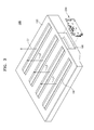
- FIG. 3 illustrates an optical housing 190 of a light scanning unit 100 and a multibeam light source unit 200 that is provided on the optical housing 190 according to an exemplary embodiment.
- the light scanning unit 100 is a device scanning multibeams, for example, four multibeams L1 through L4.
- the multibeam light source unit 200 provided on the light scanning unit 100 emits four multibeams L1 through L4.
- the optical housing 190 may be formed with, for example, plastic resin, and may be manufactured by using injection molding. On the front surface of the optical housing 190, four windows 191 through which four multibeams L1 through L4 are emitted may be formed. On one side surface of the optical housing 190, an installation unit 195, on which the multibeam light source unit 200 may be provided, may be formed. As described with reference to FIGS 12 through 14 , the optical system of the light scanning unit 100 may be provided inside the optical housing 190.
- the multibeam light source unit 200 may be provided in the installation unit 195 of the optical housing 190, and thus four multibeams L1 through L4 may be emitted from one side surface of the optical housing 190.
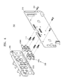
- FIG. 4 is an exploded perspective view of an exemplary multibeam light source unit 200
- FIG. 5 illustrates an example in which a middle holder 230 is coupled to a flange 220
- FIG. 6 is a perspective view of a flange 220
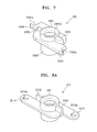
- FIG. 7 is a perspective view of a middle holder 230.
- the multibeam light source unit 200 includes light sources, for example, four light sources 110, a circuit board 210 driving and controlling the four light sources 110, a flange 220, and middle holders, for example, four middle holders 230.
- Each of the four light sources 110 may be a multibeam light source emitting a multibeam, and may be, for example, a multibeam laser diode.
- a multibeam emitted from each of the light sources 110 may be a plurality of light beams that are emitted with a predetermined interval between beams. In one scanning operation, the plurality of light beams may form, simultaneously, a plurality of scanning lines on an same scanning surface.
- the four light sources 110 each of which may be fixed to a corresponding one of the four middle holders 230, may be provided on the flange 220.
- the flange 220 supports the middle holders 230 to which the light sources are fixed, and thus the middle holders 230 may be adjusted by rotation.
- the flange 220 includes an installation surface 2201 on which four middle holders 230 may be provided.
- four holder installation holes 2202 may be formed on the installation surface 2201.
- Each of the holder installation holes 2202 may have a shape corresponding to the external shape of an insertion unit 2302 (for example, illustrated in FIG. 7 ) of the middle holder 230, and thus the insertion unit 2302 of the middle holder 230 may be inserted into the holder installation hole 2202.
- the holder installation hole 2202 may have a cylindrical aperture shape.
- the four holder installation holes 2202 may be disposed in bilateral symmetry.
- the four holder installation holes 2202 may be located in rows and columns, for example, two rows and two columns with respect to a main scanning direction (x-axis direction) and a sub scanning direction (y-axis direction). According to an arrangement of the four holder installation holes 2202, the four light sources 110 can be densely disposed in two rows and two columns, and thus the light scanning unit 100 may employ an inclined optical system.
- the main scanning direction (x-axis direction) and the sub scanning direction (y-axis direction) may be determined based on a time when the multibeam light source unit 200 is coupled to the optical housing 190 of the light scanning unit 100 as described with reference to FIGS. 12 through 14 .
- a first fixing groove unit 2203 and a second fixing groove unit 2204 may be formed in the vicinity of each of the four holder installation holes 2202.
- Each of the first and second fixing groove units 2203 and 2204 may be provided in a location in contact with a corresponding one of a first fixing protrusion unit and a second fixing protrusion unit 2303 and 2304 of FIG. 7 of the middle holder 230.
- the middle holder 230 is fixed to the flange 220 with adhesive 660 (for example, illustrated in FIG. 19E )
- the first and second fixing groove units 2203 and 2204 take at least part of the adhesive to prevent excessive adhesive from flowing around, for example, to contaminate other areas.
- the first and second fixing groove units 2203 and 2204 may be disposed in the diagonal direction centering around the holder installation holes 2202.
- the first and second fixing groove units 2203 and 2204 may be formed in a titled state with respect to the main scanning direction (x-axis direction).
- the first and second fixing groove units 2203 and 2004 may be formed, for example, by being extended in an arc shape, for example, centering around the holder installation holes 2202.
- the four pairs of the first and second fixing groove units 2203 and 2204 formed around the corresponding four holder installation holes 2202 may be disposed in bilateral symmetry on the installation surface 2201 of the flange 220. Accordingly, with securing a rotation space of the middle holder 230, the middle holder 230 can be provided in a maximum density.
- the flange 220 may include a side wall 2205 to be formed on the outside of the installation surface 2201, and thus a space in which the four middle holders 230 may be accommodated.
- the circuit board 210 may be supported by the side wall 2205 and coupled with the flange 220 by screws 290. That is, the four middle holders 230 may be disposed in a space between the flange 220 and the circuit board 210.
- the middle holder 230 may be provided to fix the light source 110 and to adjust the light source 110 by rotation. Since a multibeam emitted from the light source 110 includes a plurality of light beams, if the light source 110 is rotated, the interval between beams in the sub scanning direction of the multibeam is adjusted to a desired interval.
- the middle holders 230 may include left middle holders 230L disposed on the left-hand side of the installation surface 2201 of the flange 220 and right middle holders 230R disposed on the right-hand side of the installation surface 2201.
- the left middle holders 230L and the right middle holders 230R may have shapes of bilateral symmetry. This may correspond to the arrangement in which the first and second fixing groove units 2203 and 2204 of each of the four holder installation holes 2202 of the flange 220 are disposed in bilateral symmetry on the installation surface 2201.
- FIG. 7 an explanation referring to FIG. 7 is with respect to the left middle holder 230L.
- the right middle holder 230R may be understood as having a shape bilaterally symmetrical to that of the middle holder 230 illustrated in FIG. 7 .
- the middle holder 230 includes a light source mounting unit 2301 in which one light source 110 may be provided, an insertion unit to insert into the holder installation hole 2202 of the flange 220, a first fixing protrusion unit 2303 and a second fixing protrusion unit 2304 to fix to the flange 220, and a first jig coupling unit 2305 and a second jig coupling unit 2306 to couple with a jig 600 (for example, illustrated in FIG. 19C ).
- the light source mounting unit 2301 may have a cylinder shape having a penetration hole 2301 a.
- the shape of the penetration hole 2301a may vary according to the external shape of the light source 110. For example, if the light source 110 has a cylinder shape, the shape of the penetration hole 2301a may be a cylindrical aperture.
- the insertion unit 2301 may be inserted into the holder installation hole 2202 of the flange 220 and may have a cylinder shape. Between the insertion unit 2302 and the holder installation hole 2202, a sealing member with a low density, such as polyurethane, may be provided, and thus inflow of foreign substances through the holder installation holes 2202 of the flange 220 may be prevented after assembly.
- the insertion unit 2302 may be formed by being extended from the light source mounting unit 2301, and the penetration hole 2301a of the light source mounting unit 2301 penetrates to the end of the insertion unit 2302.
- the light source 110 pressed into the penetration hole 2301a of the light source mounting unit 2301 and 2301a may be attached to the insertion unit 2302.
- Adhesive may be applied to the first and second fixing protrusion units 2303 and 2304, and thus the middle holder 230 may be fixed to the flange 220.
- the first and second fixing protrusion units 2303 and 2304 may be formed by being extended, for example, in the diagonal direction centering around the light source mounting unit 2301, for example, in a wing shape.
- the shapes of the first and second fixing protrusion units 2303 and 2304 may be formed in rotational symmetry (in other words, point symmetry) in relation to a rotation about the light source mounting unit 2301.
- Each of the first and second fixing protrusion units 2303 and 2304 may include a corresponding one of a first concave unit 2303a and a second concave unit 2304a that may be formed by removing part of the ends of the first and second fixing protrusion units 2303 and 2304.
- the locations in which the first and second concave units 2303a and 2304a may be formed may be determined by considering a space in which the first and second fixing protrusion units 2303 and 2304 move when they rotate about the light source mounting unit 2301.
- the first concave unit 2303a of one side may have a shape in which a downstream side is concave
- the second concave unit 2304a of the other side may have a shape in which an upstream side is concave.
- both of the first and second concave units 2303a and 2304a may be formed concave on the downstream sides or upstream sides in a rotation about the light source mounting unit 2301 (that is, in a rotational symmetric form).
- first and second fixing protrusion units 2303 and 2304 and the first and second concave units 2303a and 2304a may correspond to the arrangement of the four holder installation holes 2202 in the flange 220 and the first and second fixing groove units 2203 and 2204 of the each holder installation hole 2202 as described with reference to FIGS. 5 and 6 . Accordingly, while the four middle holders 230 may be densely disposed, a space in which the first and second fixing protrusion units 2303 and 2304 move without interfering each other when adjustment is performed by rotation may be maintained, and a space in which adhesive 660 (illustrated in FIG. 19E ) is applied may be maintained. As the first and second fixing protrusion units 2303 and 2304 may be formed symmetrically about the light source mounting unit 2301, deformation of a shape by external force is dispersed, and resistance to vulnerability to characteristic changes by external environment changes improves.
- Fixing of the middle holder 230 may be performed by using adhesive after adjustment of the light source 110 (that is, adjustment of the four middle holders 230) is completed.
- the middle holder 230 By fixing the middle holder 230 by using adhesive, the influence of variation in the coupling powers of the four middle holders 230, coupling order, and intervals is minimized, and thus, distortion of the flange 220 or the middle holder 230, and position deviation may be prevented in a fixing process.
- a photopolymer adhesive may be used as the adhesive, but the types of adhesive are not limited to this.
- the first and second jig coupling units 2305 and 2306 may be coupled with the jig 600 (illustrated in FIG. 19C ) of an adjustment unit when the middle holder 230 is adjusted by rotation.
- the first and second jig coupling units 2305 and 2306 may have protrusion shapes protruding on the left and right of the light source mounting unit 2301.
- the first and second jig coupling units 2305 and 2306 may be disposed in the diagonal direction with the light source mounting unit 2301 as a center.
- the first and second jig coupling units 2305 and 2306 may have shapes different from each other. For example, as illustrated in FIG. 5 , the first and second jig coupling units 2305 and 2306 may be formed to have different thicknesses.
- the lengths or heights may be formed different from each other, or the shapes may be formed different from each other.
- the first and second jig coupling units 2305 and 2306 may have shapes different from each other, and the direction of the left and right of the middle holder 230 may be specified when assembling the multibeam light source unit 200.
- the middle holder 230 may be formed with a metallic material to enhance the heat radiation effect of the light source 110, and thus the characteristic change caused by heat may be reduced.
- the middle holder 230 may be formed with plastic resin.
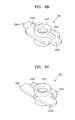
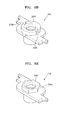
- FIGS. 8A through 8E illustrate middle holders 231, 232, 233, 234, and 235 of embodiments that may be included in a multibeam light source unit 200.
- the middle holder 230 may have first and second concave units 2303a and 2304a that are formed by removing part of the ends of the first and second fixing protrusion units 2303 and 2304.
- the middle holder 230 may be embodied in a variety of different forms.
- penetration holes 2313a and 2314a are formed at the end of the two fixing protrusion units 2313 and 2314, and thus adhesive may be applied centering around the penetration holes 2313a and 2314a and a wider area for applying the adhesive is obtained.
- the fixing protrusion units 2323 and 2324 of the middle holder 232 of FIG. 8B or in the fixing protrusion units 2333 and 2334 of the middle holder 233 of FIG. 8C there may be no separate shape changes.
- the left and right sides may be distinguished from each other, but the embodiments are not limited to this.
- the middle holder 231 in the middle holder 231, the two fixing protrusion units 2313 and 2314 and the two jig coupling units 2315 and 2316 may be formed on both sides of the light source mounting unit 2311 in rotational symmetry. Accordingly, the middle holder 231 has a rotational symmetrical shape as a whole. Referring to FIG.
- the two fixing protrusion units 2323 and 2324 are formed in bilateral symmetry on both sides of the light source mounting unit 2321, but the two jig coupling units 2325 and 2326 may be formed to have shapes different from each other.
- the two fixing protrusion units 2333 and 2334 may be formed in bilateral symmetry on both sides of the light source mounting unit 2331, but the two jig coupling units 2335 and 2336 may be formed to have shapes different from each other.
- the two fixing protrusion units 2303 and 2304 may be formed symmetrically in the diagonal direction centering around the light source mounting unit 2301.
- the middle holder 230 may be embodied in a variety of different forms.
- the two fixing protrusion units 2333 and 2334 may be formed on only one side of the light source mounting unit 2331.
- the jig coupling units 2305 and 2306 may be formed to have protrusion shapes, but may be embodied in a variety of different forms.
- the middle holder 234 may be formed to have jig coupling units 2345 and 2346 that are formed as concave grooves on both sides of the light source mounting unit 2341. More than three of protrusions or concave grooves may be formed as the jig coupling unit. Referring to FIG.
- the outer circumference surface of the light source mounting unit 2351 may be formed to have a canted column shape, and thus, the canted column shape of the outer circumference of the light source mounting unit 2351 may perform as a jig coupling unit 2355.
- the shapes of the middle holders 230 through 235 of the embodiments and modifications may be substitutes for each other within a compatible range.
- the shapes of the middle holders 230 through 235 of the embodiments and modifications may reduce the sizes of the middle holders 230 through 235, and thus, on the installation surface 2201 of the flange 220 having a limited space for installation, the middle holders 230 through 235 may be disposed densely and adjustment of positions and rotation may be performed without interference.
- the bilateral- or rotational-symmetrical shapes of the middle holders 230 through 235 symmetrically disperse changes caused by external environment changes, and thus minimize the influence of a change with the passage of time.
- middle holders 230 through 235 of the embodiments and modifications described above are explained with examples having two fixing protrusion units.
- the middle holder 230 may be embodied in a variety of different forms.
- the middle holder may have three or more protrusion units.
- FIG. 9 is a diagram of a flange 221 according to an embodiment that may be used in the multibeam light source unit 200.
- FIG. 10 illustrates an example in which a middle holder 230 is assembled to the flange 221.
- four holder installation holes 2212 may be disposed in two rows and two columns on the installation surface 2211 with respect to a main scanning direction (x-axis direction) and a sub scanning direction (y-axis direction).
- a first fixing groove unit 2213 and a second fixing groove unit 2214 may be formed in the vicinity of each of the four holder installation holes 2212.
- the first and second fixing groove units 2213 and 2214 may be disposed in the diagonal direction on the installation surface 2211 of the flange 221 centering around each of the four holder installation holes 2202.
- each of the middle holders 230 may have the first and second fixing protrusion units 2303 and 2304 that are diagonally disposed centering around the light source mounting unit 2301, and thus the middle holders 230 may be provided to the flange 221.
- the middle holders 231, 232, 234 and 235 illustrated in FIGS. 8A , 8B , 8D, and 8E may be provided to the flange 221.
- the first and second fixing groove units 2213 and 2214 may be disposed to have an identical orientation with respect to a corresponding one of the four holder installation holes 2212.
- identical middle holders 230 may be used.
- the same (left) middle holders 230 explained above with reference to FIG. 7 may be used for all the four holder installation holes 2202.
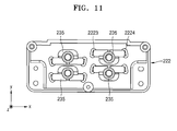
- FIG. 11 illustrates an example in which a middle holder 235 is assembled to another flange 222 that is employed in the multibeam light source unit 200 illustrated in FIG. 3 .
- four holder installation holes 2222 are disposed in two rows and two columns with respect to a main scanning direction (x-axis direction) and a sub scanning direction (y-axis direction).
- a first fixing groove unit 2223 and a second fixing groove unit 2224 may be provided in the vicinity of each of the four holder installation holes 2222.
- the first and second fixing groove units 2223 and 2224 may be disposed on one side of the holder installation hole 2222.
- This one-sided arrangement of the first and second fixing groove units 2223 and 2224 corresponds to the arrangement, described above referring to FIG. 8C , in which the two protrusion units 2333 and 2334 of the middle holder 233 are disposed on the one side of the light source mounting unit 2331.
- the embodiments of the flanges 220 through 222 and the middle holders 230 through 235, described above, are examples in which four light sources 110 may be disposed densely in two rows and two columns. Thus, a more variety of arrangements and variations may be provided additionally.
- FIG. 12 illustrates an example of optical system arrangement of the light scanning unit 100 illustrated in FIG. 3
- FIG. 13 illustrates the optical system of the optical scanning system 100 illustrated in FIG. 12 illustrated on a main scanning plane
- FIG. 14 illustrates the optical system of the optical scanning system 100 illustrated in FIG. 12 illustrated on a sub scanning plane.
- Folding of a beam path in the image forming optical system is not illustrated in FIG. 13 for simplification of drawing.
- the reflection surface of a beam deflector 150 and the folding of a beam path in the image forming optical system are not illustrated in FIG. 14 for simplification of drawing.
- Reference number 151 in FIG. 14 indicates any one reflection surface 151 of the beam deflector 150.
- the main scanning plane (or a main scanning section) may be defined as a surface on which each of the first through fourth multibeams L1 through L4 are incident when the first through fourth multibeams L1 through L4 are deflected and scanned by the rotation of the beam deflector 150.
- the main scanning plane of each of the first through fourth multibeams L1 through L4 is in parallel with both of the traveling direction and main scanning direction of each of the first through fourth multibeams L1 through L4. In other words, when reflection units 171a through 171d and 172a through 172d are in absence, main scanning plane of each of the first through fourth multibeams is perpendicular to the rotation axis of the beam deflector 150.
- the main scanning direction may be defined as a direction, seen from a scanning surface, into which the first through the fourth multibeams L1 through L4 are deflected by the rotation of the beam deflector 150.
- the sub scanning plane (or sub scanning section) may be defined as a plane orthogonal to the main scanning direction.
- the sub scanning plane is in parallel with the travelling direction and sub scanning direction of the first through fourth multibeams L1 through L4.
- the sub scanning direction may be defined as a direction of normal to the main scanning plane, and is a direction perpendicular to both the travelling direction and main scanning direction of the first through fourth multibeams L1 through L4.
- the sub scanning direction corresponds to the direction a scanning surface is moving by the rotation of a photo-sensitive drum 710 (illustrated in FIG. 20 ).
- the light scanning unit 100 includes a multibeam light source unit 200 emitting the first through fourth multibeams L1 through L4.
- the multibeam light source unit 200 includes the first through fourth light sources 110a through 110d.
- multibeam laser diodes may be provided. That is, each of the first through fourth multibeams L1 through L4 includes a plurality of light beams.
- a plurality of scanning lines may be formed on a first scanning surface 180a through a fourth scanning surface 180d in one scanning operation.
- the first through fourth multibeams L1 through L4 are expressed as one light beam for convenience of explanation.
- the first through fourth light sources 110a through 110d may emit each of the first through fourth multibeams L1 through L4 that are modulated according to image signals corresponding to, for example, image information of colors of black (K), magenta (M), yellow (Y), and cyan (C).
- the first through fourth multibeams L1 through L4 emitted from the first through fourth light sources 110a through 110d are deflected by one beam deflector 150 and scanned.
- the beam deflector 150 may be, for example, a rotating polygon mirror that has a plurality of reflecting surfaces rotating about a rotational axis.
- the beam deflector 150 may be a microelectromechanical systems (MEMS) mirror.
- MEMS microelectromechanical systems
- the first and second light sources 110a and 110B may be disposed such that the first and second multibeams L1 and L2 are incident on any one reflection surface of the beam deflector 150, and the third and fourth light sources 110C and 110d may be disposed such that the third and fourth multibeams L3 and L4 are incident on another reflection surface of the beam deflector 150. That is, as illustrated in the structure of the multibeam light source unit 200 explained referring to FIGS. 3 through 11 , the first and second light sources 110a and 110B may be disposed in a row in the sub scanning direction, and the third and fourth light sources 110C and 110d may be disposed in a row in the sub scanning direction.
- the first through fourth light sources 110a through 110d are disposed in two rows and two columns on an identical plane. Accordingly, the first through the fourth multibeams L1 through L4 emitted from the first through the fourth light sources 110a through 110d travel in the same direction.
- An incident optical system may be disposed on a beam path between the first through fourth light sources 110a through 110d and the beam deflector 150.
- the incident optical system may include collimator lenses 120a through 120d and cylindrical lenses 130ab and 130cd that are disposed on the beam paths of the first through fourth multibeams L1 through L4, respectively.
- the collimator lenses 120a through 120d are condensing lenses that make parallel beams or converging beams from the first through fourth multibeams L1 through L4 emitted from the first through fourth light sources 110a through 110d.
- the cylindrical lenses 130ab and 130cd may be anamorphic lenses that focus the first through fourth multibeams L1 through L4 in the direction corresponding to the sub scanning direction, and thus, form the first through fourth multibeams in an almost linear form on the reflection surface of the beam deflector 150.
- the first and second light sources 110a and 110B are disposed closely in the sub scanning direction and the third and fourth light sources 110C and 110d are disposed closely in the sub scanning direction
- one cylindrical lens 130ab may be shared for the first and second multibeams L1 and L2 and another cylindrical lens 130cd may be shared for the third and fourth multibeams L3 and L4.
- Cylindrical lenses 130ab and 130cd may be provided individually for each of the first through fourth multibeams L1 through L4. According to an embodiment, the collimator lenses 120a through 120d and the cylindrical lenses 130ab and 130cd may be replaced by an optical part for each beam path. On the beam path of each of the first through fourth multibeams L1 through L4, an aperture stop (not illustrated) may be provided. The aperture stop forms the luminous flux section (that is, diameter and shape) of the first through fourth multibeams L1 through L4.
- the incident optical system may be an inclined optical system in which the first through fourth multibeams L1 through L4 emitted from the first through fourth light sources 110a through 110d are made to be incident, with inclination, on the reflection surface of the beam deflector 150.
- the first multibeam L1 may be incident, with inclination, on any one reflection surface of the beam deflector 150 with a predetermined incident angle ( ⁇ ) from an upper side
- the second multibeam L2 may also be incident, with inclination, on the same reflection surface of the beam deflector 150 with a predetermined incident angle ( ⁇ ) from a lower side.
- the incident angle ( ⁇ ) of the first and second multibeams L1 and L2 may be set, for example, in a range from two degrees to four degrees inclusive.
- the incident optical system of the light scanning unit 100 may be easily implemented as an inclined optical system, by employing the multibeam light source unit 200.
- cylindrical lenses 130ab and 130cd or first imaging lenses 161 ab and 161cd may be shared, and thus the number of optical parts can be reduced to save material costs, and the light scanning unit 100 can be implemented in a smaller size.
- an imaging optical system may be disposed on the beam path between the beam deflector 150 and the first through fourth scanning surfaces 180a through 180d.
- the imaging optical system forms images of the first through fourth multibeams L1 through L4 that are deflected and scanned in the beam deflector 150, on the outer circumference surface of the photo-sensitive drums 721 (illustrated in FIG. 20 ), that is, the first through fourth scanning surfaces 180a through 180d, respectively.
- This imaging optical system may be formed with lenses having f ⁇ characteristics for correcting the first through fourth multibeams L1 through L4, and thus the first through fourth multibeams L1 through L4 are scanned at a constant velocity on the first through fourth scanning surfaces 180a through 180d.
- the imaging optical system may include first scanning lenses 161ab and 161cd and second scanning lenses 162a through 162d that are disposed on respective beam paths of the first through fourth multibeams L1 through L4.
- the first scanning lenses 161ab and 161cd may be designed to have almost zero (0) refractive power in the sub scanning direction and the second scanning lenses 162a through 162d may be designed to have a refractive power required in the sub scanning direction.
- the second scanning lenses 162a through 162d closest to a scanning surface may be eccentrically disposed, and thus a multibeam passes biased in the sub scanning direction with respect to an apex of the lens.
- the light scanning unit 100 may employ an inclined optical system, and thus the first scanning lens 160AB may be shared for the first and second multibeams L1 and L2 that are biased and scanned in parallel with an interval in a sub scanning direction.
- the other first scanning lens 160CD may be shared for the third and fourth multibeams L3 and L4 that are biased and scanned in a row with an interval in a sub scanning direction.
- a first scanning lens may be provided individually for each of the first through fourth multibeams L1 through L4.
- an imaging optical system may be formed with two scanning lenses for each beam path, but the optical system may be formed with one scanning lens for each beam path or three or more scanning lenses for each beam path.
- a synchronization detection optical system (not illustrated) in which a synchronization signal of the first through fourth multibeams L1 through L4 biased and scanned in the beam deflector 150 is detected may be provided.
- the first through fourth light sources 110a through 110d, the incident optical system, the beam deflector 150 and the imaging optical system are provided inside an optical housing 190 (illustrated in FIG. 3 ).
- reflection units 171a through 171d and 172a through 172d may be provided.
- a mirror or a total reflection prism may be employed as the reflection units 171a through 171d and 172a through 172d.
- the reflection units 171a through 171d and 172a through 172d are disposed between lenses of the imaging optical system or between the imaging optical system and the first through fourth scanning surfaces 180a through 180d, and thus a beam path may be changed appropriately.
- each of the reflection units 171a through 171d may be disposed on the beam path of a corresponding one of the first through fourth multibeams L1 through L4 between the first scanning lenses 161ab and 161cd and the second scanning lenses 162a through 162d, and each of the other reflection units 172a through 172d may be disposed on the emitting side of a corresponding one of the second scanning lenses 162a through 162d.
- beam paths of the first through fourth multibeams L1 through L2 are changed twice and directed to the first through fourth scanning surfaces 180a through 180d.
- FIG. 15 is an optical housing 390 of an optical scanning unit 300 and a multibeam light source unit 400 that is mounted on the optical housing 390 according to an exemplary embodiment.
- the light scanning unit 300 is a unit for scanning four multibeams, and may employ an inclined optical system described above with reference to FIGS. 12 through 14 .
- the multibeam light source unit 400 may be disposed such that two multibeams are incident on any one reflection surface of a beam deflector 150, and the other two multibeams are incident on the other reflection surface of the beam deflector 150.
- the multibeam light source unit 400 according to an embodiment includes a first sub light source unit 400A that emits two multibeams to any one reflection surface of the beam deflector 150, and a second sub light source unit 400B that emits two multibeams to the other reflection surface of the beam deflector 150.
- the first and second sub light source units 400A and 400B may be disposed such that the two multibeams emitted from the first sub light source unit 400A and the two multibeams emitted from the second sub light source unit 400B are in parallel or not in parallel.
- a first installation unit 395A and a second installation unit 395B on which the first and second sub light source units 400A and 400B are provided, respectively, are disposed, and thus four multibeams travel from one side of the optical housing 390.
- FIG. 16 is an exploded perspective view of the first sub light source unit 400A of the multibeam light source unit 400 illustrated in FIG. 15
- FIG. 17 illustrates an example of assembling a middle holder 430 and a flange 420 of the first sub light source unit 400A illustrated in FIG. 16 .
- the first sub light source unit 400A includes two light sources 110, a circuit board 410 driving and controlling the two light sources 110, a flange 420, and two middle holders 430.
- the two light sources 110 are fixed to the two middle holders 430, respectively, and provided to the flange 420.
- the flange 420 supports the middle holders 430 to which light sources are fixed, and thus the middle holders 430 can be adjusted by rotation.
- the flange 420 includes an installation surface 4201 on which the two middle holders are provided. On the installation surface 4201, two holder installation holes are provided. The middle holders 430 are inserted into the holder installation holes 4202, respectively.
- the two holder installation holes 4202 may be disposed with an interval in a sub scanning direction (y-axis direction). According to this arrangement of the two holder installation holes 4202, the two light sources 110 may emit two multibeams with an interval in the sub scanning direction (y-axis direction), and the two multibeams are made to be incident on any one reflection surface of the beam deflector 150 (illustrated in FIG. 15 ).
- a first fixing groove unit 4203 and a second fixing groove unit 4204 may be further provided in the vicinity of the two holder installation holes 4202, respectively.
- the first and second fixing groove units 4203 and 4204 may be formed in a diagonal direction centering around the holder installation holes 4202, or in bilateral symmetry. In order to correspond to the adjustment of the middle holders 430 by rotation, the first and second fixing groove units 4203 and 4204 may be formed by being extended in an arc shape centering around the holder installation holes 4202. On the installation surface 4201 of the flange 420, two pairs of the first and second fixing groove units 4203 and 4204 may be disposed in bilateral symmetry.
- the middle holders 430 may include a left middle holder 430A and a right middle holder 430B which are in bilateral symmetry. These middle holders 430 may be the middle holders 230 described above with reference to FIG. 7 .
- the middle holders 430 may be one of the middle holders 231 through 235 of the embodiments described above with reference to FIGS. 8A through 8E .
- the left middle holder 430A and the right middle holder 430B enable adjustment by rotation without interfering each other and can narrow the interval in the sub scanning direction (y-axis direction).
- the flange 420 may include a side wall 4205 to be formed on the outside of the installation surface 4201, and thus a space in which the two middle holders 430 are accommodated. As illustrated in FIG. 15 , the circuit board 410 is supported by the side wall 4205 and coupled with the flange 420 by screws 490.
- the second sub light source unit 400B of the multibeam light source unit 400 may have a structure symmetric to that of the first sub light source unit 400A with respect to the main scanning direction (x-axis direction).
- the multibeam light source units 200 and 400 may have two or four light sources 100, but embodiments are not limited to this. For example, three or five or more light sources may be provided to one flange.
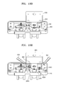
- FIG. 18 is a flowchart explaining a method of adjusting a multibeam light source unit according to an exemplary embodiment
- FIGS. 19A through 19F are diagrams explaining exemplary operations of the method of adjusting a multibeam light source unit illustrated in FIG. 18 .
- adjustment and fixing of the multibeam light source unit may be performed first and then, the adjusted multibeam light source unit 200 and 400 is fixed to the optical housing 190 and 310 of the light scanning unit 100 and 300.
- the multibeam light source unit 200 explained above with reference to FIGS. 3 through FIG. 7 is further explained as an example.
- a light source 110 may be pressed into the cylinder type penetration hole 2301 a of the insertion unit 2302 of the middle holder 230.
- a pressing-in unit 610 of a jig of adjusting equipment holds the first and second jig coupling units 2305 and 2306 of the middle holder 230, and inserts the insertion unit 2302 of the middle holder 230 into one of a plurality of holder installation holes 220 of the flange in operation S520.
- the first and second fixing protrusion units 2303 and 2304 on both sides of the middle holder 230 may be placed to be hung on top of a corresponding one of the first and second fixing groove units 2203 and 2204.
- the left and right sides of the middle holder 230 are determined. Accordingly, the pressing-in unit 610 of the jig 600 inserts the middle holder 230 into the holder installation hole 2202 with the left and right sides of the middle holder 230 held in correction positions.
- power may be provided to the light source 110 through the jig 600 in operation S530.
- adjustment of at least one direction among upward, downward, left, right, and rotation directions may be performed in order for a multibeam to have predetermined position and interval in operation S540.
- a multibeam emitted from the light source 110 is formed with a plurality of light beams, and thus a plurality of scanning lines may be formed on a scanning surface at one scanning operation. Accordingly, if the light source 110 is rotated, the interval between beams of the multibeam in the sub scanning direction can be adjusted to a desired interval.
- photopolymer adhesive 660 may be applied on and around the positions on top of the flange, corresponding to the first and second fixing protrusion units 2303 and 2304 having a wing shape and protruding on the left and right sides of the middle holder 230 of which position is adjusted.
- ultraviolet light source 650 ultraviolet beams may be applied to harden the photopolymer adhesive and fixe the middle holder 230 in operation S550.
- the operations for adjusting the light source 110 described above with reference to FIGS. 19A through 19E may be performed repeatedly until installation of all light sources 110 are completed in operation S560.
- an assembly process may be performed in which assembling of the multibeam light source unit 200 may be completed by attaching the flange 220 to the circuit board 210 and the multibeam light source unit 200 of which assembling is completed may be installed on the housing 190 of the light scanning unit 200.
- the middle holder 230 according to an embodiment, enables minimizing the size of the middle holder 230 itself, and through simplification of the jig coupling unit (for example, the first and second jig coupling units 2305 and 2306 of FIG. 7 ), enables simultaneous adjustment of multiple middle holders 230. Thus, required working hours is reduced and material costs can be saved through miniaturization.
- operation S510 may be repeated for all light sources 110 and, operations S520 through S550 may be performed simultaneously for all middle holders 230.
- photopolymer adhesive 660 is applied after adjusting the middle holder 230 .
- photopolymer adhesive 660 may be applied before adjusting the middle holder 230 (that is, before operation S530), and after the adjustment (that is, after operation S540), ultraviolet beams may be applied to harden the photopolymer adhesive 660 to fix the middle holder 230.
- photopolymer adhesive 660 is explained as an example, but adhesive such as thermosetting adhesive and super glue may also be employed.
- FIG. 20 is a diagram illustrating an electrophotography type image forming apparatus 700 according to an exemplary embodiment.
- the image forming apparatus illustrated in FIG. 20 is a dry electrophotography type image forming apparatus which uses dry developer (hereinafter referred to as 'toner') and prints color images.
- 'toner' dry developer
- the image forming apparatus includes a light scanning unit 710, a developer unit 720, an intermediate transfer belt 730, a first transfer roller 731, a second transfer roller 732, and a fuser unit 740. These units are accommodated in a cabinet 790.
- the light scanning unit 710 is a unit scanning a plurality of multibeams, and may be the light scanning units of the embodiments described above with reference to FIGS. 1 through 19F .
- the light scanning unit 710 may scan four multibeams corresponding colors of black (K), magenta (M), yellow (Y), and cyan (C).
- K black
- M magenta
- Y yellow
- C cyan
- a plurality of scanning lines may be formed on the first through fourth scanning surfaces 180a through 180d in one scanning operation, and thus, printing speed is enhanced.
- the developer unit 720 may be provided for each color corresponding to a plurality of multibeams.
- the developer unit 720 may be provided for each of the colors, black (K), magenta (M), yellow (Y), and cyan (C).
- the developer unit 720 includes a photosensitive drum 721 which is an image receiver on which electrostatic latent image is formed for each color, and developer roller 722 which develops the electrostatic latent images.
- the photosensitive drum 721 is an example of a photoreceptor.
- a photosensitive layer with a predetermined thickness is formed on the outer circumference surface of a cylindrical metal pipe.
- the outer circumference surface of the photosensitive drum 721 is a scanning surface.
- the photosensitive drum 720 is exposed to the outside of the developer unit 720 and is disposed with a predetermined interval in the sub scanning direction.
- a photosensitive belt having a belt shape may be employed as a photoreceptor.
- a charging roller 723 is provided on the upstream side of a position that is exposed to light by the light scanning unit 710 on the outer circumference surface of the photosensitive drum.
- the charging roller 723 is an example of a charger that charges the surface of the photosensitive drum 721 to a uniform electric potential, with rotating in contact with the photosensitive drum 721.
- a charging bias is applied to the charging roller 723.
- a corona charger (not illustrated) may be used instead of the charging roller 723.
- the developer roller 722 provides toner to the photosensitive drum 721, by attaching toner on the outer circumference of the developer roller 722.
- a developing bias to provide the toner to the photosensitive drum 721 is applied to the developer roller 722.
- each of the developer unit 720 may further include a supplying roller that attaches toner, that is accommodated in the developer unit 720, to the developer roller 722, a control unit that controls the amount of toner attached to the developer roller 722, and an agitator (not illustrated) to deliver the toner accommodated in the developer unit 720, to the supplying roller and/or developer roller 722 side.
- the intermediate transfer belt 730 faces the outer circumference surface of the photosensitive drum 721 exposed to the outside of the developer unit 720.
- the intermediate transfer belt 730 is an example of an intermediate transfer unit transferring the toner image of the photosensitive drum 71 to paper P.
- an intermediate transfer drum may be employed as an intermediate transfer unit.
- the intermediate transfer belt 730 performs cyclic runs in contact with the photosensitive drum 721.
- Each of four first transfer rollers 731 is disposed to face a corresponding photosensitive drum 721 with the intermediate transfer belt 730 in between.
- a first transfer bias may be applied to the first transfer roller 731, and thus a toner image of the photosensitive drum 721 is transferred to the intermediate transfer belt 730.
- a second transfer roller 732 may be disposed to face the intermediate transfer belt 730 such that paper P passes between them.
- a second transfer bias may be applied to the second transfer roller 732, and thus the toner image of the intermediate transfer belt 730 is transferred to the paper P.
- a process for forming a color image is disclosed.
- the photosensitive drum 721 of each developer unit 720 is charged to a uniform electric potential by the charging bias applied to the charge roller 723.
- the light scanning unit 710 exposes to light, the scanning surface of the photosensitive drum 721 in the length direction, that is, the main scanning direction. As the photosensitive drum 721 rotates, the scanning surface moves to the sub scanning direction, and thus two-dimensional electrostatic latent images corresponding to image information of colors, black (K), magenta (M), yellow (Y), and cyan (C), are formed on the scanning surface of each of the four photosensitive drums 721, respectively.
- the sub scanning direction is a direction perpendicular to the main scanning direction.
- the four developer units 720 provide tones of respective colors, black (K), magenta (M), yellow (Y), and cyan (C), to the photosensitive drums 721, and thus, tone images of colors, black (K), magenta (M), yellow (Y), and cyan (C), are formed.
- the toner images of colors, black (K), magenta (M), yellow (Y), and cyan (C), formed on the photosensitive drums 721, respectively, are transferred to the intermediate transfer belt 730 in an overlapping manner by the first transfer bias applied to the first transfer roller 731, and thus a color toner image is formed.
- a medium that finally receives the toner, for example, the paper P, may be transferred by a pickup roller 761 and a transport roller 762, and guided into between the intermediate belt 720 and the second transfer roller 732.
- the color toner image transferred to the intermediate transfer belt 730 may be transferred to the paper P by the second transfer bias applied to the second transfer roller 732.
- the color toner image transferred on the paper P may be kept on the surface of the paper P by electrostatic power.
- the paper P on which the color toner image is transferred is sent to the fuser unit 740.
- the color toner image transferred on the paper P receives heat and pressure in the fusing nip of the fuser unit 740, and fused to the paper P.
- the paper P on which fusing is completed is discharged to the outside of the image forming apparatus by a discharge roller 763.
- the image forming apparatus is explained with an example of forming a color image, but embodiments are not limited to this.
- the light scanning unit 710 may scan one multibeam and the developer unit 720 may be provided for only one multibeam.
- the elements of the image forming apparatus, except the image scanning unit 100, that is, the developer unit 720, the intermediate transfer belt 730, the first and second transfer rollers 731 and 732, the fuser unit 740, are explained as an example of printing unit that transfers a toner image onto a printing medium in an electrophotography method.
- Various types of printing units may be applied to the image forming apparatus according to the embodiments.
Landscapes
- Physics & Mathematics (AREA)
- General Physics & Mathematics (AREA)
- Engineering & Computer Science (AREA)
- General Engineering & Computer Science (AREA)
- Optics & Photonics (AREA)
- Facsimile Scanning Arrangements (AREA)
- Mechanical Optical Scanning Systems (AREA)
Abstract
Description
- This application is related to, and claims the priority benefit of, Korean Patent Application No.
10-2013-0142375 filed on November 21, 2013 - One or more embodiments relate to a multibeam light source unit, a method of adjusting the unit, a light scanning unit, and an electrophotography type image forming apparatus, and more particularly, to a multibeam light source unit in which adjustment of light sources is easy in an assembly process, a method of adjusting the unit, a light scanning unit, and an electrophotography type image forming apparatus.
- An electrophotography type image forming apparatus, such as a laser printer, a digital copying machine, and a multifunction printer (MFP), has a structure in which by emitting a light beam to a photoreceptor through a light scanning device, an electrostatic latent image is formed, the formed electrostatic latent image is developed to a development image by using a developer such as a toner, and the development image is transferred on a printing medium.
- In an image forming apparatus, a multibeam light scanning unit, which records a plurality of lines by using a plurality of light beams, may be used in order to improve the printing speed. A multibeam light scanning unit uses a light source, which emits at least two light beams (hereinafter, referred to as a multibeam), such as a multibeam laser diode. For the image forming apparatus to implement a color image, the light scanning unit has a plurality of light sources to be modulated by an image signal corresponding to image information of a plurality of single colors, for example, black (K), magenta (M), yellow (Y), cyan (C).
- In a multibeam light scanning unit, adjustment of interval between beams of a multibeam may be performed by rotating light sources. For example, as illustrated in
FIG. 1 , a multibeam light scanning unit includes alight source 1 fixed to anoptical housing 8 by using alight source holder 5. Thelight source holder 5 may be coupled with theoptical housing 8 by using screws. Adjustment of intervals between beams of thelight source 1 may be performed by pressing thelight source 1 into thelight source holder 5 and grabbing and turning a grip unit 5A of thelight source holder 5. As an example, as illustrated inFIG. 2 , an optical scanning unit has a structure in which anLD unit 40 is formed by pressing twolaser diodes holder 55 with aleaf spring 65 pressing theLD unit 40 into an installation hole of anoptical housing 60. Adjustment of rotation of theLD unit 40 is performed by turning anadjustment screw 71 of an adjustmentdevice maintenance unit 58. - In the rotation adjustment structure of the conventional multibeam light scanning unit, there are problems of deformation in a fixing process after adjusting a light source, and vulnerability to external environment changes. For example, in a structure in which a light source holder is fixed to an optical housing by a coupling unit, such as screws, even though a grip unit of the light source holder is fixed, the optical housing and the light source holder may be deformed by variation in the coupling power of the screws, the order of coupling the screws, and changes in the coupling torque. In a structure in which a light source holder is equipped with an elastic unit, such as a leaf spring, variation in the spring tension occurs because of the simple fixing by the spring tension, and a gap as big as the allowance between the optical housing and the light source holder occurs. This structure is vulnerable to external shock. Also, when the internal and external temperatures of the multibeam light scanning unit increases, it is highly likely that a deformation occurs because of the asymmetrical shape of the light source holder. Because of these problems, the position of a beam emitted from a light source changes and the position on the surface of a photoreceptor becomes incorrect.
- When an existing single light beam is used, the sensitivity of the rotational angle of a light source may not matter. However, when a multibeam, formed with two or more light beams is used, the sensitivity of the rotational angle of a light source increases. For example, in order to maintain an existing performance, the angle tolerance of a light source using two beams may be, for example, approximately 14 degrees. However, when a light source using four beams is used, the angle tolerance may be, for example, within 1.5 degrees and thus the sensitivity increases, for example, by 9.3 times or more. In an image forming apparatus using one beam, deterioration in the picture quality due to this problem may be small, but in a color image forming apparatus using a plurality of light sources with a plurality of photoreceptors, this causes incorrect image colors and thus degrades the quality of an image.
- A light scanning unit using a tilted incident beam may reduce the size and material cost of a light scanning unit having a plurality of mounted light sources because it has compact light path layout and smaller number of parts. In a light scanning unit using a tilted incident beam, a plurality of light sources may be disposed with narrow intervals. However, it is not easy to mount a plurality of light sources with narrow intervals because of issues of size, shape, and fixing method of light source holders that are used in the conventional assembly of light sources.
- One or more embodiments include a multibeam light source unit in which adjustment of light sources is easily performed and that has a compact structure, a method of adjusting the multibeam light source unit, a light scanning unit, and an electrophotography type image forming apparatus.
- Additional aspects will be set forth in part in the description that follows and, in part, will be apparent from the description, or may be learned by practice of the presented embodiments.
- According to the present invention there is provided an apparatus and method as set forth in the appended claims. Other features of the invention will be apparent from the dependent claims, and the description which follows.
- According to one or more embodiments, a multibeam light source unit includes a plurality of light sources that emit multibeam, respectively, a flange that has an installation surface on which a plurality of holder installation holes are provided, and a plurality of middle holders on each of which a corresponding one of the plurality of light sources is provided, wherein each of the plurality of the middle holders includes a light source mounting unit on which one of the plurality of the light sources is provided, a cylinder-shape insertion unit that is inserted into one of the plurality of the holder installation holes, a first fixing protrusion unit and a second fixing protrusion unit, each of which is protruding outside from the light source mounting unit and is fixed to the flange by adhesive; and a jig coupling unit that is coupled with a jig when adjustment is performed.
- In the multibeam light source unit, the plurality of holder installation holes may be disposed in rows and columns in a main scanning direction and in a sub scanning direction, respectively.
- For example, the plurality of holder installation holes may be four holder installation holes, and the four holder installation holes may be disposed in two rows and two columns in a main scanning direction and in a sub scanning direction, respectively.
- The plurality of holder installation holes may be two holder installation holes and the two holder installation holes may be disposed with an interval in a sub scanning direction.
- In the multibeam light source unit, the flange may include a first fixing groove unit and a second fixing groove unit concavely formed in the vicinity of each of the plurality of holder installation holes.
- The first and second fixing groove units may be formed by being extended in an arc shape centering around a corresponding one of the plurality of holder installation holes.
- The first and second fixing groove units may be formed at positions to be in contact with a first fixing protrusion unit and a second fixing protrusion unit, respectively, of the plurality of the middle holders.
- The plurality of holder installation holes and the first and second fixing groove units may be formed in bilateral symmetry or rotational symmetry on the installation surface of the flange.
- The flange may be formed of plastic resin.
- The light source mounting unit may include a penetration hole into which the light source is pressed in, and the penetration hole may penetrate to the end of the insertion unit.
- The outer circumference surface of the light source mounting unit may be formed in a canted column shape, and the canted column shape of the light source mounting unit may perform as a jig coupling unit.
- The first and second fixing protrusion units may be disposed in bilateral symmetry or rotational symmetry with respect to the light source mounting unit.
- In each of the first and second fixing protrusion units, part of the end may be removed or a penetration hole may be formed at the end.
- The plurality of middle holders may be fixed to the flange with photopolymer adhesive.
- Each of the first and second jig coupling units may have a protrusion shape protruding from circumference of the light source mounting unit.
- Each of the first and second jig coupling units may have a concave groove shape concavely formed in circumference of the light source mounting unit.
- The first and second jig coupling units may be disposed in bilateral symmetry or rotational symmetry with respect to the light source mounting unit.
- The first and second jig coupling units may have shapes different from each other.
- The plurality of middle holders may be made of metal or plastic resin.
- The multibeam light source unit may further include a circuit board that is provided on the installation surface of the flange, and drives and controls the plurality of light sources.
- The plurality of middle holders may be disposed between the flange and the circuit board.
- The flange may include a side wall disposed outside of the installation surface to provide a space that accommodates the plurality of middle holders, and the circuit board may be supported by the side wall.
- The plurality of light sources may be multibeam laser diodes.
- According to one or more embodiments, a method of adjusting a multibeam light source unit includes providing a light source on a light source mounting unit of a middle holder, with a jig of adjustment equipment holding a jig coupling unit of the middle holder, inserting the light source mounting unit of the middle holder into any one of a plurality of holder installation holes disposed on an installation surface of a flange, providing power to the light source through the jig, with detecting the position and interval of a multibeam emitted from the light source, adjusting at least one of the upward, downward, left, right and rotation directions of the middle holder so that the multibeam has a predetermined position and interval, and fixing to the flange by adhesive, a first fixing protrusion unit and a second fixing protrusion unit formed to protrude outside from the light source mounting unit of the middle holder.
- The operations may be repeated until all the light sources are provided to the plurality of holder installation holes of the flange.
- In the operation for providing a light source on a light source mounting unit of a middle holder, light sources may be provided to the same number of the plurality of middle holders as the number of the plurality of holder installation holes of the flange, and the other operations may be simultaneously performed for the plurality of middle holders.
- The jig may determine the direction of the middle holder according to the shapes of the jig coupling unit of the middle holder.
- The adhesive may be photopolymer adhesive, and the fixing of the first and second protrusion unit to the flange may include applying the adhesive on and around the first and second fixing protrusion units of the middle holder, and hardening the adhesive by exposing an ultraviolet beam to the adhesive.
- The applying the adhesive may be performed before or after adjusting at least one of the upward, downward, left, right and rotation directions of the middle holder.
- The method may include attaching a circuit board that drives and controls the light source, on the installation surface of the flange on which the light source is provided, after completing adjusting and providing the light source on the flange.
- The method may comprise attaching the flange on housing of light scanning unit, after completing adjusting and providing the light source on the flange.
- According to one or more embodiments, a light scanning unit includes: a multibeam light source unit, a beam deflector that deflects and scans a plurality of multibeams emitted from the multibeam light source unit, an incident optical system that makes the plurality of multibeams emitted from the multibeam light source unit, incident on the beam deflector, and an imaging optical system that enables the multibeam deflected by the beam deflector, to form an image on a scanning surface, wherein the multibeam light source unit includes: a plurality of light sources that emit multibeam, respectively, a flange that has an installation surface on which a plurality of holder installation holes are provided, and a plurality of middle holders on each of which a corresponding one of the plurality of light sources is provided, wherein each of the plurality of the middle holders includes: a light source mounting unit on which one of the plurality of the light sources is provided, a cylinder-shape insertion unit that is inserted into one of the plurality of the holder installation holes, a first fixing protrusion unit and a second fixing protrusion unit, each of which is protruding outside from the light source mounting unit and is fixed to the flange by adhesive, and a jig coupling unit that is coupled with a jig when adjustment is performed.
- The incident optical system may be an inclined optical system that enables at least two multibeams among the plurality of multibeams, to be incident, with inclination, on one reflection surface of the beam deflector.
- According to one or more embodiments, an electrophotography type image forming apparatus includes a light scanning unit that comprises a multibeam light source unit, a beam deflector that deflects and scans a plurality of multibeams emitted from the multibeam light source unit, an incident optical system that makes the plurality of multibeams emitted from the multibeam light source unit, incident on the beam deflector, and an imaging optical system that enables the multibeam deflected by the beam deflector, to form an image on a scanning surface, a developer unit that comprises a plurality of photoreceptors each of which is disposed where an image of a corresponding one of the plurality of multibeams emitted from the light scanning unit is formed, and on which an electrostatic latent image is formed, and a developer roller that develops the electrostatic latent images formed on the plurality of photoreceptors, and a transfer unit onto that the image developed by the developer unit is transferred, wherein the multibeam light source unit includes a plurality of light sources that emit multibeam, respectively, a flange that has an installation surface on which a plurality of holder installation holes are provided, and a plurality of middle holders on each of which a corresponding one of the plurality of light sources is provided, wherein each of the plurality of the middle holders includes a light source mounting unit on which one of the plurality of the light sources is provided, a cylinder-shape insertion unit that is inserted into one of the plurality of the holder installation holes, a first fixing protrusion unit and a second fixing protrusion unit, each of which is protruding outside from the light source mounting unit and is fixed to the flange by adhesive, and a jig coupling unit that is coupled with a jig when adjustment is performed.
- In the multibeam light source unit and the method of adjusting the multibeam light source unit according to the embodiments described above, it is easy to adjust the position and rotation of a light source in an assembly process, and by using adhesive, an assembly process can be reduced.
- In the multibeam light source unit and the method of adjusting the multibeam light source unit according to the embodiments described above, the problems of deformation in a fixing process and vulnerability to external environment changes in the structure in which intervals between beams of a multibeam are adjusted are solved.
- The light scanning unit employing a multibeam light source unit and the electrophotography type image forming apparatus according to the embodiments, described above, have a compact structure such as an optical system with a titled incident beam, and provide high quality color images.
- These and/or other aspects will become apparent and more readily appreciated from the following description of the embodiments, taken in conjunction with the accompanying drawings in which:
-
FIGS. 1 and2 are diagrams schematically showing structures for adjustment of a light source unit; -
FIG. 3 illustrates an optical housing of a light scanning unit and a multibeam light source unit that is mounted on the optical housing according to an exemplary embodiment; -
FIG. 4 is an exemplary exploded perspective view of a multibeam light source unit; -
FIG. 5 illustrates an example in which a middle holder is coupled to a flange in a multibeam light source unit; -
FIG. 6 is a perspective view of an exemplary flange of a multibeam light source unit; -
FIG. 7 is a perspective view of an exemplary middle holder of the multibeam light source unit; -
FIGS. 8A through 8E illustrate exemplary middle holders in a multibeam light source unit; -
FIG. 9 illustrates an exemplary flange in a multibeam light source unit; -
FIG. 10 illustrates an example in which a middle holder is assembled to a flange; -
FIG. 11 illustrates an example in which a middle holder is assembled to a flange in a multibeam light source unit; -
FIG. 12 illustrates an example of optical system arrangement of a light scanning unit; -
FIG. 13 illustrates an exemplary optical system of an optical scanning system on a main scanning plane; -
FIG. 14 illustrates an exemplary optical system of an optical scanning system on a sub scanning plane; -
FIG. 15 is an optical housing of an optical scanning unit and a multibeam light source unit that is mounted on the optical housing according to an exemplary embodiment; -
FIG. 16 is an exploded perspective view of an exemplary multibeam light source unit; -
FIG. 17 illustrates an example in which a middle holder is coupled to a flange in a multibeam light source unit; -
FIG. 18 is a flowchart illustrating a method of adjusting a multibeam light source unit according to an exemplary embodiment; -
FIGS. 19A through 19F illustrate exemplary operations of a method of adjusting a multibeam light source unit; and -
FIG. 20 is a diagram illustrating an electrophotography type image forming apparatus according to an exemplary embodiment. - Reference will now be made in detail to embodiments, examples of which are illustrated in the accompanying drawings, wherein like reference numerals refer to like elements throughout. In the drawings, a size and thickness an element may be exaggerated for clarity.
- As used herein, the term "and/or" includes any and all combinations of one or more of the associated listed items. Expressions such as "at least one of," when preceding a list of elements, modify the entire list of elements and do not modify the individual elements of the list.
-
FIG. 3 illustrates anoptical housing 190 of alight scanning unit 100 and a multibeamlight source unit 200 that is provided on theoptical housing 190 according to an exemplary embodiment. - Referring to
FIG. 3 , thelight scanning unit 100 is a device scanning multibeams, for example, four multibeams L1 through L4. The multibeamlight source unit 200 provided on thelight scanning unit 100 emits four multibeams L1 through L4. - The
optical housing 190 may be formed with, for example, plastic resin, and may be manufactured by using injection molding. On the front surface of theoptical housing 190, four windows 191 through which four multibeams L1 through L4 are emitted may be formed. On one side surface of theoptical housing 190, aninstallation unit 195, on which the multibeamlight source unit 200 may be provided, may be formed. As described with reference toFIGS 12 through 14 , the optical system of thelight scanning unit 100 may be provided inside theoptical housing 190. - The multibeam
light source unit 200 may be provided in theinstallation unit 195 of theoptical housing 190, and thus four multibeams L1 through L4 may be emitted from one side surface of theoptical housing 190. -
FIG. 4 is an exploded perspective view of an exemplary multibeamlight source unit 200,FIG. 5 illustrates an example in which amiddle holder 230 is coupled to aflange 220,FIG. 6 is a perspective view of aflange 220, andFIG. 7 is a perspective view of amiddle holder 230. - Referring to
FIG. 4 , the multibeamlight source unit 200 includes light sources, for example, fourlight sources 110, acircuit board 210 driving and controlling the fourlight sources 110, aflange 220, and middle holders, for example, fourmiddle holders 230. - Each of the four
light sources 110 may be a multibeam light source emitting a multibeam, and may be, for example, a multibeam laser diode. A multibeam emitted from each of thelight sources 110 may be a plurality of light beams that are emitted with a predetermined interval between beams. In one scanning operation, the plurality of light beams may form, simultaneously, a plurality of scanning lines on an same scanning surface. - The four
light sources 110, each of which may be fixed to a corresponding one of the fourmiddle holders 230, may be provided on theflange 220. - The
flange 220 supports themiddle holders 230 to which the light sources are fixed, and thus themiddle holders 230 may be adjusted by rotation. Referring toFIGS. 5 and 6 , theflange 220 includes aninstallation surface 2201 on which fourmiddle holders 230 may be provided. On theinstallation surface 2201, fourholder installation holes 2202 may be formed. Each of theholder installation holes 2202 may have a shape corresponding to the external shape of an insertion unit 2302 (for example, illustrated inFIG. 7 ) of themiddle holder 230, and thus theinsertion unit 2302 of themiddle holder 230 may be inserted into theholder installation hole 2202. For example, if theinsertion unit 2302 of themiddle holder 230 has a cylinder shape, theholder installation hole 2202 may have a cylindrical aperture shape. The fourholder installation holes 2202 may be disposed in bilateral symmetry. - The four
holder installation holes 2202 may be located in rows and columns, for example, two rows and two columns with respect to a main scanning direction (x-axis direction) and a sub scanning direction (y-axis direction). According to an arrangement of the fourholder installation holes 2202, the fourlight sources 110 can be densely disposed in two rows and two columns, and thus thelight scanning unit 100 may employ an inclined optical system. The main scanning direction (x-axis direction) and the sub scanning direction (y-axis direction) may be determined based on a time when the multibeamlight source unit 200 is coupled to theoptical housing 190 of thelight scanning unit 100 as described with reference toFIGS. 12 through 14 . - On the
installation surface 2201 of theflange 220, a firstfixing groove unit 2203 and a secondfixing groove unit 2204 may be formed in the vicinity of each of the four holder installation holes 2202. Each of the first and second fixinggroove units fixing protrusion unit FIG. 7 of themiddle holder 230. When themiddle holder 230 is fixed to theflange 220 with adhesive 660 (for example, illustrated inFIG. 19E ), the first and second fixinggroove units groove units groove units protrusion units middle holder 230 is adjusted byrotation 239, the first and second fixinggroove units 2203 and 2004 may be formed, for example, by being extended in an arc shape, for example, centering around the holder installation holes 2202. The four pairs of the first and second fixinggroove units holder installation holes 2202 may be disposed in bilateral symmetry on theinstallation surface 2201 of theflange 220. Accordingly, with securing a rotation space of themiddle holder 230, themiddle holder 230 can be provided in a maximum density. - The
flange 220 may include aside wall 2205 to be formed on the outside of theinstallation surface 2201, and thus a space in which the fourmiddle holders 230 may be accommodated. As illustrated in FIG. , thecircuit board 210 may be supported by theside wall 2205 and coupled with theflange 220 byscrews 290. That is, the fourmiddle holders 230 may be disposed in a space between theflange 220 and thecircuit board 210. - The
middle holder 230 may be provided to fix thelight source 110 and to adjust thelight source 110 by rotation. Since a multibeam emitted from thelight source 110 includes a plurality of light beams, if thelight source 110 is rotated, the interval between beams in the sub scanning direction of the multibeam is adjusted to a desired interval. - As illustrated in
FIGS. 4 and5 , themiddle holders 230 may include leftmiddle holders 230L disposed on the left-hand side of theinstallation surface 2201 of theflange 220 and rightmiddle holders 230R disposed on the right-hand side of theinstallation surface 2201. The leftmiddle holders 230L and the rightmiddle holders 230R may have shapes of bilateral symmetry. This may correspond to the arrangement in which the first and second fixinggroove units holder installation holes 2202 of theflange 220 are disposed in bilateral symmetry on theinstallation surface 2201. Hereinafter, an explanation referring toFIG. 7 is with respect to the leftmiddle holder 230L. The rightmiddle holder 230R may be understood as having a shape bilaterally symmetrical to that of themiddle holder 230 illustrated inFIG. 7 . - Referring to
FIG. 7 , themiddle holder 230 includes a lightsource mounting unit 2301 in which onelight source 110 may be provided, an insertion unit to insert into theholder installation hole 2202 of theflange 220, a firstfixing protrusion unit 2303 and a secondfixing protrusion unit 2304 to fix to theflange 220, and a firstjig coupling unit 2305 and a secondjig coupling unit 2306 to couple with a jig 600 (for example, illustrated inFIG. 19C ). - The light
source mounting unit 2301 may have a cylinder shape having apenetration hole 2301 a. The shape of thepenetration hole 2301a may vary according to the external shape of thelight source 110. For example, if thelight source 110 has a cylinder shape, the shape of thepenetration hole 2301a may be a cylindrical aperture. - The
insertion unit 2301 may be inserted into theholder installation hole 2202 of theflange 220 and may have a cylinder shape. Between theinsertion unit 2302 and theholder installation hole 2202, a sealing member with a low density, such as polyurethane, may be provided, and thus inflow of foreign substances through theholder installation holes 2202 of theflange 220 may be prevented after assembly. Theinsertion unit 2302 may be formed by being extended from the lightsource mounting unit 2301, and thepenetration hole 2301a of the lightsource mounting unit 2301 penetrates to the end of theinsertion unit 2302. Thelight source 110 pressed into thepenetration hole 2301a of the lightsource mounting unit insertion unit 2302. - Adhesive may be applied to the first and second fixing
protrusion units middle holder 230 may be fixed to theflange 220. The first and second fixingprotrusion units source mounting unit 2301, for example, in a wing shape. In other words, except the shapes of a firstconcave unit 2303a and a second concave unit 2304B as described later, the shapes of the first and second fixingprotrusion units source mounting unit 2301. - Each of the first and second fixing
protrusion units concave unit 2303a and a secondconcave unit 2304a that may be formed by removing part of the ends of the first and second fixingprotrusion units concave units protrusion units source mounting unit 2301. For example, when themiddle holder 230 rotates clockwise about the lightsource mounting unit 2301, the firstconcave unit 2303a of one side may have a shape in which a downstream side is concave, and the secondconcave unit 2304a of the other side may have a shape in which an upstream side is concave. As an example, both of the first and secondconcave units - These shapes of the first and second fixing
protrusion units concave units holder installation holes 2202 in theflange 220 and the first and second fixinggroove units holder installation hole 2202 as described with reference toFIGS. 5 and 6 . Accordingly, while the fourmiddle holders 230 may be densely disposed, a space in which the first and second fixingprotrusion units FIG. 19E ) is applied may be maintained. As the first and second fixingprotrusion units source mounting unit 2301, deformation of a shape by external force is dispersed, and resistance to vulnerability to characteristic changes by external environment changes improves. - Fixing of the
middle holder 230 may be performed by using adhesive after adjustment of the light source 110 (that is, adjustment of the four middle holders 230) is completed. By fixing themiddle holder 230 by using adhesive, the influence of variation in the coupling powers of the fourmiddle holders 230, coupling order, and intervals is minimized, and thus, distortion of theflange 220 or themiddle holder 230, and position deviation may be prevented in a fixing process. Considering convenience of fixing, a photopolymer adhesive may be used as the adhesive, but the types of adhesive are not limited to this. - The first and second
jig coupling units FIG. 19C ) of an adjustment unit when themiddle holder 230 is adjusted by rotation. The first and secondjig coupling units source mounting unit 2301. The first and secondjig coupling units source mounting unit 2301 as a center. The first and secondjig coupling units FIG. 5 , the first and secondjig coupling units jig coupling units middle holder 230 may be specified when assembling the multibeamlight source unit 200. - The
middle holder 230 may be formed with a metallic material to enhance the heat radiation effect of thelight source 110, and thus the characteristic change caused by heat may be reduced. Themiddle holder 230 may be formed with plastic resin. -
FIGS. 8A through 8E illustratemiddle holders light source unit 200. - In order to secure a wider area to which adhesive 660 (for example, illustrated in
FIG. 19E ) is applied, themiddle holder 230 explained with reference toFIG. 5 , may have first and secondconcave units protrusion units middle holder 230 may be embodied in a variety of different forms. For example, in themiddle holder 231 illustrated inFIG. 8A ,penetration holes protrusion units penetration holes protrusion units middle holder 232 ofFIG. 8B or in the fixingprotrusion units middle holder 233 ofFIG. 8C , there may be no separate shape changes. - In the
middle holder 230 explained with reference toFIG. 5 , the left and right sides may be distinguished from each other, but the embodiments are not limited to this. For example, referring toFIG. 8A , in themiddle holder 231, the two fixingprotrusion units jig coupling units source mounting unit 2311 in rotational symmetry. Accordingly, themiddle holder 231 has a rotational symmetrical shape as a whole. Referring toFIG. 8B , in themiddle holder 232, the two fixingprotrusion units source mounting unit 2321, but the twojig coupling units - As illustrated in
FIG. 8C , in themiddle holder 233, the two fixingprotrusion units source mounting unit 2331, but the twojig coupling units - In the
middle holder 230 explained with reference toFIG. 5 , the two fixingprotrusion units source mounting unit 2301. Themiddle holder 230 may be embodied in a variety of different forms. For example, referring toFIG. 8C , in themiddle holder 233, the two fixingprotrusion units source mounting unit 2331. - In the
middle holder 230 explained with reference toFIG. 5 , thejig coupling units FIG. 8D , themiddle holder 234 may be formed to havejig coupling units source mounting unit 2341. More than three of protrusions or concave grooves may be formed as the jig coupling unit. Referring toFIG. 8E , in themiddle holder 235, the outer circumference surface of the lightsource mounting unit 2351 may be formed to have a canted column shape, and thus, the canted column shape of the outer circumference of the lightsource mounting unit 2351 may perform as ajig coupling unit 2355. - The shapes of the
middle holders 230 through 235 of the embodiments and modifications may be substitutes for each other within a compatible range. - The shapes of the
middle holders 230 through 235 of the embodiments and modifications may reduce the sizes of themiddle holders 230 through 235, and thus, on theinstallation surface 2201 of theflange 220 having a limited space for installation, themiddle holders 230 through 235 may be disposed densely and adjustment of positions and rotation may be performed without interference. - Through minimization of the size of the
middle holders 230 through 235 and simplification of jig coupling units, adjustment processes of multiplemiddle holders 230 through 235 may be performed simultaneously to reduce working hours and through miniaturization, material cost may be reduced. - The bilateral- or rotational-symmetrical shapes of the
middle holders 230 through 235 symmetrically disperse changes caused by external environment changes, and thus minimize the influence of a change with the passage of time. - The
middle holders 230 through 235 of the embodiments and modifications described above are explained with examples having two fixing protrusion units. However, themiddle holder 230 may be embodied in a variety of different forms. The middle holder may have three or more protrusion units. -
FIG. 9 is a diagram of aflange 221 according to an embodiment that may be used in the multibeamlight source unit 200.FIG. 10 illustrates an example in which amiddle holder 230 is assembled to theflange 221. Referring toFIGS. 9 and 10 , in theflange 221, fourholder installation holes 2212 may be disposed in two rows and two columns on theinstallation surface 2211 with respect to a main scanning direction (x-axis direction) and a sub scanning direction (y-axis direction). A firstfixing groove unit 2213 and a secondfixing groove unit 2214 may be formed in the vicinity of each of the four holder installation holes 2212. The first and second fixinggroove units installation surface 2211 of theflange 221 centering around each of the four holder installation holes 2202. As described with reference toFIG. 7 , each of themiddle holders 230 may have the first and second fixingprotrusion units source mounting unit 2301, and thus themiddle holders 230 may be provided to theflange 221. Themiddle holders FIGS. 8A ,8B ,8D, and 8E may be provided to theflange 221. - The first and second fixing
groove units groove units holder installation holes 2212, identicalmiddle holders 230 may be used. For example, the same (left)middle holders 230 explained above with reference toFIG. 7 may be used for all the four holder installation holes 2202. -
FIG. 11 illustrates an example in which amiddle holder 235 is assembled to anotherflange 222 that is employed in the multibeamlight source unit 200 illustrated inFIG. 3 . Referring toFIG. 11 , on the installation surface 2221 of theflange 222 according to an embodiment, four holder installation holes 2222 are disposed in two rows and two columns with respect to a main scanning direction (x-axis direction) and a sub scanning direction (y-axis direction). A firstfixing groove unit 2223 and a secondfixing groove unit 2224 may be provided in the vicinity of each of the four holder installation holes 2222. The first and second fixinggroove units groove units FIG. 8C , in which the twoprotrusion units middle holder 233 are disposed on the one side of the lightsource mounting unit 2331. - The embodiments of the
flanges 220 through 222 and themiddle holders 230 through 235, described above, are examples in which fourlight sources 110 may be disposed densely in two rows and two columns. Thus, a more variety of arrangements and variations may be provided additionally. -
FIG. 12 illustrates an example of optical system arrangement of thelight scanning unit 100 illustrated inFIG. 3 ,FIG. 13 illustrates the optical system of theoptical scanning system 100 illustrated inFIG. 12 illustrated on a main scanning plane, andFIG. 14 illustrates the optical system of theoptical scanning system 100 illustrated inFIG. 12 illustrated on a sub scanning plane. Folding of a beam path in the image forming optical system is not illustrated inFIG. 13 for simplification of drawing. Likewise, the reflection surface of abeam deflector 150 and the folding of a beam path in the image forming optical system are not illustrated inFIG. 14 for simplification of drawing.Reference number 151 inFIG. 14 indicates any onereflection surface 151 of thebeam deflector 150. The main scanning plane (or a main scanning section) may be defined as a surface on which each of the first through fourth multibeams L1 through L4 are incident when the first through fourth multibeams L1 through L4 are deflected and scanned by the rotation of thebeam deflector 150. The main scanning plane of each of the first through fourth multibeams L1 through L4 is in parallel with both of the traveling direction and main scanning direction of each of the first through fourth multibeams L1 through L4. In other words, whenreflection units 171a through 171d and 172a through 172d are in absence, main scanning plane of each of the first through fourth multibeams is perpendicular to the rotation axis of thebeam deflector 150. The main scanning direction may be defined as a direction, seen from a scanning surface, into which the first through the fourth multibeams L1 through L4 are deflected by the rotation of thebeam deflector 150. The sub scanning plane (or sub scanning section) may be defined as a plane orthogonal to the main scanning direction. The sub scanning plane is in parallel with the travelling direction and sub scanning direction of the first through fourth multibeams L1 through L4. The sub scanning direction may be defined as a direction of normal to the main scanning plane, and is a direction perpendicular to both the travelling direction and main scanning direction of the first through fourth multibeams L1 through L4. The sub scanning direction corresponds to the direction a scanning surface is moving by the rotation of a photo-sensitive drum 710 (illustrated inFIG. 20 ). - Referring to
FIGS. 12 through 14 , thelight scanning unit 100 according to an embodiment includes a multibeamlight source unit 200 emitting the first through fourth multibeams L1 through L4. The multibeamlight source unit 200 includes the first through fourthlight sources 110a through 110d. As the first through fourthlight sources 110a through 110d, multibeam laser diodes may be provided. That is, each of the first through fourth multibeams L1 through L4 includes a plurality of light beams. As each of the first through fourth multibeams L1 through L4 is a multibeam, a plurality of scanning lines may be formed on afirst scanning surface 180a through afourth scanning surface 180d in one scanning operation. InFIGS. 12 through 14 , the first through fourth multibeams L1 through L4 are expressed as one light beam for convenience of explanation. The first through fourthlight sources 110a through 110d may emit each of the first through fourth multibeams L1 through L4 that are modulated according to image signals corresponding to, for example, image information of colors of black (K), magenta (M), yellow (Y), and cyan (C). - The first through fourth multibeams L1 through L4 emitted from the first through fourth
light sources 110a through 110d are deflected by onebeam deflector 150 and scanned. Thebeam deflector 150 may be, for example, a rotating polygon mirror that has a plurality of reflecting surfaces rotating about a rotational axis. As an example, thebeam deflector 150 may be a microelectromechanical systems (MEMS) mirror. - The first and second
light sources 110a and 110B may be disposed such that the first and second multibeams L1 and L2 are incident on any one reflection surface of thebeam deflector 150, and the third and fourthlight sources 110C and 110d may be disposed such that the third and fourth multibeams L3 and L4 are incident on another reflection surface of thebeam deflector 150. That is, as illustrated in the structure of the multibeamlight source unit 200 explained referring toFIGS. 3 through 11 , the first and secondlight sources 110a and 110B may be disposed in a row in the sub scanning direction, and the third and fourthlight sources 110C and 110d may be disposed in a row in the sub scanning direction. In other words, the first through fourthlight sources 110a through 110d are disposed in two rows and two columns on an identical plane. Accordingly, the first through the fourth multibeams L1 through L4 emitted from the first through thefourth light sources 110a through 110d travel in the same direction. - An incident optical system may be disposed on a beam path between the first through fourth
light sources 110a through 110d and thebeam deflector 150. The incident optical system may includecollimator lenses 120a through 120d and cylindrical lenses 130ab and 130cd that are disposed on the beam paths of the first through fourth multibeams L1 through L4, respectively. Thecollimator lenses 120a through 120d are condensing lenses that make parallel beams or converging beams from the first through fourth multibeams L1 through L4 emitted from the first through fourthlight sources 110a through 110d. The cylindrical lenses 130ab and 130cd may be anamorphic lenses that focus the first through fourth multibeams L1 through L4 in the direction corresponding to the sub scanning direction, and thus, form the first through fourth multibeams in an almost linear form on the reflection surface of thebeam deflector 150. As the first and secondlight sources 110a and 110B are disposed closely in the sub scanning direction and the third and fourthlight sources 110C and 110d are disposed closely in the sub scanning direction, one cylindrical lens 130ab may be shared for the first and second multibeams L1 and L2 and another cylindrical lens 130cd may be shared for the third and fourth multibeams L3 and L4. Cylindrical lenses 130ab and 130cd may be provided individually for each of the first through fourth multibeams L1 through L4. According to an embodiment, thecollimator lenses 120a through 120d and the cylindrical lenses 130ab and 130cd may be replaced by an optical part for each beam path. On the beam path of each of the first through fourth multibeams L1 through L4, an aperture stop (not illustrated) may be provided. The aperture stop forms the luminous flux section (that is, diameter and shape) of the first through fourth multibeams L1 through L4. - The incident optical system may be an inclined optical system in which the first through fourth multibeams L1 through L4 emitted from the first through fourth
light sources 110a through 110d are made to be incident, with inclination, on the reflection surface of thebeam deflector 150. For example, as illustrated inFIG. 14 , the first multibeam L1 may be incident, with inclination, on any one reflection surface of thebeam deflector 150 with a predetermined incident angle (θ) from an upper side, and the second multibeam L2 may also be incident, with inclination, on the same reflection surface of thebeam deflector 150 with a predetermined incident angle (θ) from a lower side. The incident angle (θ) of the first and second multibeams L1 and L2 may be set, for example, in a range from two degrees to four degrees inclusive. In order to design an inclined optical system with this incident optical system, it may be necessary to densely dispose the first through fourthlight sources 110a through 110d. As the first through fourthlight sources 110a through 110d of the multibeamlight source unit 200, described above with reference toFIGS. 3 through 11 , can be densely disposed, the incident optical system of thelight scanning unit 100 may be easily implemented as an inclined optical system, by employing the multibeamlight source unit 200. By designing an incident optical system as an inclined optical system, cylindrical lenses 130ab and 130cd or first imaging lenses 161 ab and 161cd may be shared, and thus the number of optical parts can be reduced to save material costs, and thelight scanning unit 100 can be implemented in a smaller size. - On the beam path between the
beam deflector 150 and the first throughfourth scanning surfaces 180a through 180d, an imaging optical system may be disposed. - The imaging optical system forms images of the first through fourth multibeams L1 through L4 that are deflected and scanned in the
beam deflector 150, on the outer circumference surface of the photo-sensitive drums 721 (illustrated inFIG. 20 ), that is, the first throughfourth scanning surfaces 180a through 180d, respectively. - This imaging optical system may be formed with lenses having fθ characteristics for correcting the first through fourth multibeams L1 through L4, and thus the first through fourth multibeams L1 through L4 are scanned at a constant velocity on the first through
fourth scanning surfaces 180a through 180d. For example, the imaging optical system may include first scanning lenses 161ab and 161cd andsecond scanning lenses 162a through 162d that are disposed on respective beam paths of the first through fourth multibeams L1 through L4. The first scanning lenses 161ab and 161cd may be designed to have almost zero (0) refractive power in the sub scanning direction and thesecond scanning lenses 162a through 162d may be designed to have a refractive power required in the sub scanning direction. Thesecond scanning lenses 162a through 162d closest to a scanning surface may be eccentrically disposed, and thus a multibeam passes biased in the sub scanning direction with respect to an apex of the lens. - The
light scanning unit 100 according to an embodiment may employ an inclined optical system, and thus the first scanning lens 160AB may be shared for the first and second multibeams L1 and L2 that are biased and scanned in parallel with an interval in a sub scanning direction. The other first scanning lens 160CD may be shared for the third and fourth multibeams L3 and L4 that are biased and scanned in a row with an interval in a sub scanning direction. By sharing the first lenses 161ab and 161cd, the number of optical parts may be reduced and thelight scanning unit 100 may be implemented in a smaller size. A first scanning lens may be provided individually for each of the first through fourth multibeams L1 through L4. According to an exemplary embodiment, an imaging optical system may be formed with two scanning lenses for each beam path, but the optical system may be formed with one scanning lens for each beam path or three or more scanning lenses for each beam path. - A synchronization detection optical system (not illustrated) in which a synchronization signal of the first through fourth multibeams L1 through L4 biased and scanned in the
beam deflector 150 is detected may be provided. - The first through fourth
light sources 110a through 110d, the incident optical system, thebeam deflector 150 and the imaging optical system are provided inside an optical housing 190 (illustrated inFIG. 3 ). - To implement the
light scanning unit 100 in a smaller size, and to scan the first through fourth multibeams L1 through L4 in a predetermined direction in thelight scanning unit 100,reflection units 171a through 171d and 172a through 172d may be provided. As thereflection units 171a through 171d and 172a through 172d, a mirror or a total reflection prism may be employed. Thereflection units 171a through 171d and 172a through 172d are disposed between lenses of the imaging optical system or between the imaging optical system and the first throughfourth scanning surfaces 180a through 180d, and thus a beam path may be changed appropriately. For example, each of thereflection units 171a through 171d may be disposed on the beam path of a corresponding one of the first through fourth multibeams L1 through L4 between the first scanning lenses 161ab and 161cd and thesecond scanning lenses 162a through 162d, and each of theother reflection units 172a through 172d may be disposed on the emitting side of a corresponding one of thesecond scanning lenses 162a through 162d. Thus, beam paths of the first through fourth multibeams L1 through L2 are changed twice and directed to the first throughfourth scanning surfaces 180a through 180d. -
FIG. 15 is anoptical housing 390 of anoptical scanning unit 300 and a multibeamlight source unit 400 that is mounted on theoptical housing 390 according to an exemplary embodiment. - Referring to
FIG. 15 , thelight scanning unit 300 according to an embodiment is a unit for scanning four multibeams, and may employ an inclined optical system described above with reference toFIGS. 12 through 14 . The multibeamlight source unit 400 may be disposed such that two multibeams are incident on any one reflection surface of abeam deflector 150, and the other two multibeams are incident on the other reflection surface of thebeam deflector 150. For this, the multibeamlight source unit 400 according to an embodiment includes a first sublight source unit 400A that emits two multibeams to any one reflection surface of thebeam deflector 150, and a second sublight source unit 400B that emits two multibeams to the other reflection surface of thebeam deflector 150. The first and second sublight source units light source unit 400A and the two multibeams emitted from the second sublight source unit 400B are in parallel or not in parallel. On one side of theoptical housing 390, afirst installation unit 395A and asecond installation unit 395B on which the first and second sublight source units optical housing 390. -
FIG. 16 is an exploded perspective view of the first sublight source unit 400A of the multibeamlight source unit 400 illustrated inFIG. 15 , andFIG. 17 illustrates an example of assembling amiddle holder 430 and aflange 420 of the first sublight source unit 400A illustrated inFIG. 16 . - Referring to
FIG. 16 , the first sublight source unit 400A includes twolight sources 110, acircuit board 410 driving and controlling the twolight sources 110, aflange 420, and twomiddle holders 430. The twolight sources 110 are fixed to the twomiddle holders 430, respectively, and provided to theflange 420. - The
flange 420 supports themiddle holders 430 to which light sources are fixed, and thus themiddle holders 430 can be adjusted by rotation. Theflange 420 includes aninstallation surface 4201 on which the two middle holders are provided. On theinstallation surface 4201, two holder installation holes are provided. Themiddle holders 430 are inserted into theholder installation holes 4202, respectively. The twoholder installation holes 4202 may be disposed with an interval in a sub scanning direction (y-axis direction). According to this arrangement of the twoholder installation holes 4202, the twolight sources 110 may emit two multibeams with an interval in the sub scanning direction (y-axis direction), and the two multibeams are made to be incident on any one reflection surface of the beam deflector 150 (illustrated inFIG. 15 ). - On the
installation surface 4201 of theflange 420, a firstfixing groove unit 4203 and a secondfixing groove unit 4204 may be further provided in the vicinity of the twoholder installation holes 4202, respectively. - The first and second fixing
groove units holder installation holes 4202, or in bilateral symmetry. In order to correspond to the adjustment of themiddle holders 430 by rotation, the first and second fixinggroove units installation surface 4201 of theflange 420, two pairs of the first and second fixinggroove units - Corresponding to the bilaterally symmetrical arrangement of the two pairs of the first and second fixing
groove units installation surface 4201 of the flange, similarly to the example illustrated in FIGS. and 5, themiddle holders 430 may include a leftmiddle holder 430A and a rightmiddle holder 430B which are in bilateral symmetry. Thesemiddle holders 430 may be themiddle holders 230 described above with reference toFIG. 7 . Themiddle holders 430 may be one of themiddle holders 231 through 235 of the embodiments described above with reference toFIGS. 8A through 8E . - The left
middle holder 430A and the rightmiddle holder 430B enable adjustment by rotation without interfering each other and can narrow the interval in the sub scanning direction (y-axis direction). - The
flange 420 may include aside wall 4205 to be formed on the outside of theinstallation surface 4201, and thus a space in which the twomiddle holders 430 are accommodated. As illustrated inFIG. 15 , thecircuit board 410 is supported by theside wall 4205 and coupled with theflange 420 byscrews 490. - The second sub
light source unit 400B of the multibeamlight source unit 400 may have a structure symmetric to that of the first sublight source unit 400A with respect to the main scanning direction (x-axis direction). - The multibeam
light source units light sources 100, but embodiments are not limited to this. For example, three or five or more light sources may be provided to one flange. - A method of adjusting a multibeam light source unit according to an embodiment disclosed.
-
FIG. 18 is a flowchart explaining a method of adjusting a multibeam light source unit according to an exemplary embodiment, andFIGS. 19A through 19F are diagrams explaining exemplary operations of the method of adjusting a multibeam light source unit illustrated inFIG. 18 . - According to an exemplary embodiment, adjustment and fixing of the multibeam light source unit (200 of
FIG. 3 , 400 ofFIG. 15 ) may be performed first and then, the adjusted multibeamlight source unit optical housing 190 and 310 of thelight scanning unit light source unit 200 explained above with reference toFIGS. 3 through FIG. 7 is further explained as an example. - Referring to 19A and 19B, first, a
light source 110 may be pressed into the cylindertype penetration hole 2301 a of theinsertion unit 2302 of themiddle holder 230. As illustrated inFIG. 19C , a pressing-inunit 610 of a jig of adjusting equipment holds the first and secondjig coupling units middle holder 230, and inserts theinsertion unit 2302 of themiddle holder 230 into one of a plurality ofholder installation holes 220 of the flange in operation S520. The first and second fixingprotrusion units middle holder 230 may be placed to be hung on top of a corresponding one of the first and second fixinggroove units jig coupling units middle holder 230 are different from each other, the left and right sides of themiddle holder 230 are determined. Accordingly, the pressing-inunit 610 of thejig 600 inserts themiddle holder 230 into theholder installation hole 2202 with the left and right sides of themiddle holder 230 held in correction positions. - As illustrated in
FIG. 19D , power may be provided to thelight source 110 through thejig 600 in operation S530. With detecting the location and interval of a multibeam emitted from thelight source 110, adjustment of at least one direction among upward, downward, left, right, and rotation directions may be performed in order for a multibeam to have predetermined position and interval in operation S540. A multibeam emitted from thelight source 110 is formed with a plurality of light beams, and thus a plurality of scanning lines may be formed on a scanning surface at one scanning operation. Accordingly, if thelight source 110 is rotated, the interval between beams of the multibeam in the sub scanning direction can be adjusted to a desired interval. - Referring to
FIG. 19E ,photopolymer adhesive 660 may be applied on and around the positions on top of the flange, corresponding to the first and second fixingprotrusion units middle holder 230 of which position is adjusted. With an ultravioletlight source 650, ultraviolet beams may be applied to harden the photopolymer adhesive and fixe themiddle holder 230 in operation S550. By fixing themiddle holder 230 using the adhesive like this, the difference between before and after fixing is minimized. Also, easier assembly and less deviation is enabled. - The operations for adjusting the
light source 110 described above with reference toFIGS. 19A through 19E , may be performed repeatedly until installation of alllight sources 110 are completed in operation S560. - After the operations for adjusting the
light source 110 are completed, an assembly process may be performed in which assembling of the multibeamlight source unit 200 may be completed by attaching theflange 220 to thecircuit board 210 and the multibeamlight source unit 200 of which assembling is completed may be installed on thehousing 190 of thelight scanning unit 200. - According to an exemplary embodiment, an example in which the
middle holders 230 into which thelight sources 110 are pressed are installed one by one is explained, but embodiments are not limited to this. Themiddle holder 230 according to an embodiment enables minimizing the size of themiddle holder 230 itself, and through simplification of the jig coupling unit (for example, the first and secondjig coupling units FIG. 7 ), enables simultaneous adjustment of multiplemiddle holders 230. Thus, required working hours is reduced and material costs can be saved through miniaturization. When adjustment of a plurality ofmiddle holder 230 is performed at the same time, operation S510 may be repeated for alllight sources 110 and, operations S520 through S550 may be performed simultaneously for allmiddle holders 230. - According to an exemplary embodiment, an example in which photopolymer adhesive 660 is applied after adjusting the
middle holder 230 is explained. However, according, for example, to convenience of operations,photopolymer adhesive 660 may be applied before adjusting the middle holder 230 (that is, before operation S530), and after the adjustment (that is, after operation S540), ultraviolet beams may be applied to harden thephotopolymer adhesive 660 to fix themiddle holder 230. According to an exemplary embodiment,photopolymer adhesive 660 is explained as an example, but adhesive such as thermosetting adhesive and super glue may also be employed. -
FIG. 20 is a diagram illustrating an electrophotography typeimage forming apparatus 700 according to an exemplary embodiment. The image forming apparatus illustrated inFIG. 20 is a dry electrophotography type image forming apparatus which uses dry developer (hereinafter referred to as 'toner') and prints color images. - The image forming apparatus includes a
light scanning unit 710, a developer unit 720, anintermediate transfer belt 730, afirst transfer roller 731, asecond transfer roller 732, and afuser unit 740. These units are accommodated in acabinet 790. - The
light scanning unit 710 is a unit scanning a plurality of multibeams, and may be the light scanning units of the embodiments described above with reference toFIGS. 1 through 19F . For example, thelight scanning unit 710 may scan four multibeams corresponding colors of black (K), magenta (M), yellow (Y), and cyan (C). As described above, as each of the first through fourth light beams L1 through L4 is a multibeam, a plurality of scanning lines may be formed on the first throughfourth scanning surfaces 180a through 180d in one scanning operation, and thus, printing speed is enhanced. - The developer unit 720 may be provided for each color corresponding to a plurality of multibeams. For example, the developer unit 720 may be provided for each of the colors, black (K), magenta (M), yellow (Y), and cyan (C). The developer unit 720 includes a
photosensitive drum 721 which is an image receiver on which electrostatic latent image is formed for each color, and developer roller 722 which develops the electrostatic latent images. - The
photosensitive drum 721 is an example of a photoreceptor. In the photosensitive drum, a photosensitive layer with a predetermined thickness is formed on the outer circumference surface of a cylindrical metal pipe. The outer circumference surface of thephotosensitive drum 721 is a scanning surface. The photosensitive drum 720 is exposed to the outside of the developer unit 720 and is disposed with a predetermined interval in the sub scanning direction. Instead of thephotosensitive drum 721, a photosensitive belt having a belt shape may be employed as a photoreceptor. - A charging
roller 723 is provided on the upstream side of a position that is exposed to light by thelight scanning unit 710 on the outer circumference surface of the photosensitive drum. The chargingroller 723 is an example of a charger that charges the surface of thephotosensitive drum 721 to a uniform electric potential, with rotating in contact with thephotosensitive drum 721. A charging bias is applied to the chargingroller 723. A corona charger (not illustrated) may be used instead of the chargingroller 723. The developer roller 722 provides toner to thephotosensitive drum 721, by attaching toner on the outer circumference of the developer roller 722. A developing bias to provide the toner to thephotosensitive drum 721 is applied to the developer roller 722. Though not illustrated in drawings, each of the developer unit 720 may further include a supplying roller that attaches toner, that is accommodated in the developer unit 720, to the developer roller 722, a control unit that controls the amount of toner attached to the developer roller 722, and an agitator (not illustrated) to deliver the toner accommodated in the developer unit 720, to the supplying roller and/or developer roller 722 side. - The
intermediate transfer belt 730 faces the outer circumference surface of thephotosensitive drum 721 exposed to the outside of the developer unit 720. Theintermediate transfer belt 730 is an example of an intermediate transfer unit transferring the toner image of thephotosensitive drum 71 to paper P. Instead of theintermediate transfer belt 730, an intermediate transfer drum may be employed as an intermediate transfer unit. Theintermediate transfer belt 730 performs cyclic runs in contact with thephotosensitive drum 721. Each of fourfirst transfer rollers 731 is disposed to face a correspondingphotosensitive drum 721 with theintermediate transfer belt 730 in between. A first transfer bias may be applied to thefirst transfer roller 731, and thus a toner image of thephotosensitive drum 721 is transferred to theintermediate transfer belt 730. - A
second transfer roller 732 may be disposed to face theintermediate transfer belt 730 such that paper P passes between them. A second transfer bias may be applied to thesecond transfer roller 732, and thus the toner image of theintermediate transfer belt 730 is transferred to the paper P. - A process for forming a color image is disclosed.
- The
photosensitive drum 721 of each developer unit 720 is charged to a uniform electric potential by the charging bias applied to thecharge roller 723. - The
light scanning unit 710 exposes to light, the scanning surface of thephotosensitive drum 721 in the length direction, that is, the main scanning direction. As thephotosensitive drum 721 rotates, the scanning surface moves to the sub scanning direction, and thus two-dimensional electrostatic latent images corresponding to image information of colors, black (K), magenta (M), yellow (Y), and cyan (C), are formed on the scanning surface of each of the fourphotosensitive drums 721, respectively. The sub scanning direction is a direction perpendicular to the main scanning direction. The four developer units 720 provide tones of respective colors, black (K), magenta (M), yellow (Y), and cyan (C), to thephotosensitive drums 721, and thus, tone images of colors, black (K), magenta (M), yellow (Y), and cyan (C), are formed. - The toner images of colors, black (K), magenta (M), yellow (Y), and cyan (C), formed on the
photosensitive drums 721, respectively, are transferred to theintermediate transfer belt 730 in an overlapping manner by the first transfer bias applied to thefirst transfer roller 731, and thus a color toner image is formed. - A medium that finally receives the toner, for example, the paper P, may be transferred by a
pickup roller 761 and atransport roller 762, and guided into between the intermediate belt 720 and thesecond transfer roller 732. - The color toner image transferred to the
intermediate transfer belt 730 may be transferred to the paper P by the second transfer bias applied to thesecond transfer roller 732. The color toner image transferred on the paper P may be kept on the surface of the paper P by electrostatic power. The paper P on which the color toner image is transferred is sent to thefuser unit 740. The color toner image transferred on the paper P receives heat and pressure in the fusing nip of thefuser unit 740, and fused to the paper P. The paper P on which fusing is completed is discharged to the outside of the image forming apparatus by adischarge roller 763. - The image forming apparatus is explained with an example of forming a color image, but embodiments are not limited to this. For example, when an image of a monochrome of black and white is formed, the
light scanning unit 710 may scan one multibeam and the developer unit 720 may be provided for only one multibeam. The elements of the image forming apparatus, except theimage scanning unit 100, that is, the developer unit 720, theintermediate transfer belt 730, the first andsecond transfer rollers fuser unit 740, are explained as an example of printing unit that transfers a toner image onto a printing medium in an electrophotography method. Various types of printing units may be applied to the image forming apparatus according to the embodiments. - The multibeam light source unit, the method of adjusting the unit, the light scanning unit, and the electrophotography type image forming apparatus are explained above with reference to the embodiments illustrated on the drawings in order to help understanding. While one or more embodiments have been described with reference to the figures, it will be understood by those of ordinary skill in the art that various changes in form and details may be made therein without departing from the scope of the present invention as defined by the following claims.
- Attention is directed to all papers and documents which are filed concurrently with or previous to this specification in connection with this application and which are open to public inspection with this specification, and the contents of all such papers and documents are incorporated herein by reference.
- All of the features disclosed in this specification (including any accompanying claims, abstract and drawings), and/or all of the steps of any method or process so disclosed, may be combined in any combination, except combinations where at least some of such features and/or steps are mutually exclusive.
- Each feature disclosed in this specification (including any accompanying claims, abstract and drawings) may be replaced by alternative features serving the same, equivalent or similar purpose, unless expressly stated otherwise. Thus, unless expressly stated otherwise, each feature disclosed is one example only of a generic series of equivalent or similar features.
- The invention is not restricted to the details of the foregoing embodiment(s). The invention extends to any novel one, or any novel combination, of the features disclosed in this specification (including any accompanying claims, abstract and drawings), or to any novel one, or any novel combination, of the steps of any method or process so disclosed.
Claims (15)
- A multibeam light source unit comprising:a plurality of light sources that emit a multibeam, respectively;a flange that has an installation surface on which a plurality of holder installation holes are provided; anda plurality of middle holders on each of which a corresponding one of the plurality of light sources is provided,wherein each of the plurality of the middle holders comprises:a light source mounting unit on which one of the plurality of the light sources is provided,a cylinder-shape insertion unit that is inserted into one of the plurality of the holder installation holes,a first fixing protrusion unit and a second fixing protrusion unit, each of which is protruding outside from the light source mounting unit and is fixed to the flange by adhesive, anda jig coupling unit that is coupled with a jig when adjustment is performed.
- The multibeam light source unit of claim 1, wherein the plurality of holder installation holes are disposed in rows and columns in a main scanning direction and in a sub scanning direction, respectively.
- The multibeam light source unit of any one of claims 1 or 2, wherein the plurality of holder installation holes are two holder installation holes and the two holder installation holes are disposed with an interval in a sub scanning direction.
- The multibeam light source unit of any one of claims 1 to 3, wherein the flange comprise a first fixing groove unit and a second fixing groove unit concavely formed in the vicinity of each of the plurality of holder installation holes.
- The multibeam light source unit of claim any one of claims 1 to 4, wherein the light source mounting unit comprises a penetration hole into which the light source is pressed in, and the penetration hole penetrates to the end of the insertion unit.
- The multibeam light source unit of any one of claims 1 to 5, wherein the outer circumference surface of the light source mounting unit is formed in a canted column shape, and the canted column shape of the light source mounting unit performs as a jig coupling unit.
- The multibeam light source unit of any one of claims 1 to 6, wherein in each of the first and second fixing protrusion units, part of the end is removed or a penetration hole is formed at the end.
- The multibeam light source unit of any one of claims 1 to 7, wherein each of the first and second jig coupling units has a protrusion shape protruding from circumference of the light source mounting unit.
- The multibeam light source unit of any one of claims 1 to 8, further comprising a circuit board that is provided on the installation surface of the flange, and drives and controls the plurality of light sources.
- The multibeam light source unit of claim 9, wherein the plurality of middle holders are disposed between the flange and the circuit board.
- The multibeam light source unit of claim 10, wherein the flange comprises a side wall disposed outside of the installation surface to provide a space that accommodates the plurality of middle holders, and the circuit board is supported by the side wall.
- A method of adjusting a multibeam light source unit comprising:providing a light source on a light source mounting unit of a middle holder;inserting, with a jig of adjustment equipment holding a jig coupling unit of the middle holder, the light source mounting unit of the middle holder into any one of a plurality of holder installation holes disposed on an installation surface of a flange;providing power to the light source through the jig;adjusting, with detecting the position and interval of a multibeam emitted from the light source, at least one of the upward, downward, left, right and rotation directions of the middle holder so that the multibeam has a predetermined position and interval; andfixing to the flange by adhesive, a first fixing protrusion unit and a second fixing protrusion unit formed to protrude outside from the light source mounting unit of the middle holder.
- The method of claim 12, wherein the adhesive is photopolymer adhesive, and the fixing of the first and second protrusion unit to the flange comprises:applying the adhesive on and around the first and second fixing protrusion units of the middle holder, andhardening the adhesive by exposing an ultraviolet beam to the adhesive.
- The method of any one of claims 12 or 13, further comprising attaching a circuit board that drives and controls the light source, on the installation surface of the flange on which the light source is provided, after completing adjusting and providing the light source on the flange.
- The method of any one of claims 12 to 14, further comprising attaching the flange on housing of light scanning unit, after completing adjusting and providing the light source on the flange.
Applications Claiming Priority (1)
| Application Number | Priority Date | Filing Date | Title |
|---|---|---|---|
| KR1020130142375A KR20150058970A (en) | 2013-11-21 | 2013-11-21 | Multibeam light source unit, method of adjusting the same, light scanning unit, and electrophotography type image forming apparatus |
Publications (2)
| Publication Number | Publication Date |
|---|---|
| EP2875957A1 true EP2875957A1 (en) | 2015-05-27 |
| EP2875957B1 EP2875957B1 (en) | 2019-07-03 |
Family
ID=51900082
Family Applications (1)
| Application Number | Title | Priority Date | Filing Date |
|---|---|---|---|
| EP14189097.0A Not-in-force EP2875957B1 (en) | 2013-11-21 | 2014-10-15 | Multibeam light source unit, method of adjusting the same, light scanning unit, and electrophotography type image forming apparatus |
Country Status (4)
| Country | Link |
|---|---|
| US (1) | US9329520B2 (en) |
| EP (1) | EP2875957B1 (en) |
| KR (1) | KR20150058970A (en) |
| CN (1) | CN104656250B (en) |
Families Citing this family (5)
| Publication number | Priority date | Publication date | Assignee | Title |
|---|---|---|---|---|
| JP6531914B2 (en) * | 2016-08-30 | 2019-06-19 | 京セラドキュメントソリューションズ株式会社 | Optical scanning device and image forming apparatus provided with optical scanning device |
| JP7159837B2 (en) * | 2018-12-13 | 2022-10-25 | ブラザー工業株式会社 | optical scanner |
| JP7358898B2 (en) * | 2019-10-09 | 2023-10-11 | ブラザー工業株式会社 | scanning optical device |
| JP7612365B2 (en) * | 2020-09-25 | 2025-01-14 | キヤノン株式会社 | Optical scanning device and image forming device |
| CN117908517B (en) * | 2023-12-29 | 2024-06-11 | 杭州广安汽车电器有限公司 | Automobile air conditioner controller detection platform based on simulation system |
Citations (3)
| Publication number | Priority date | Publication date | Assignee | Title |
|---|---|---|---|---|
| US20080063023A1 (en) * | 2006-06-05 | 2008-03-13 | Canon Kabushiki Kaisha | Optical scanning apparatus |
| EP2447756A1 (en) * | 2010-11-02 | 2012-05-02 | Samsung Electronics Co., Ltd. | Light scanning unit and electrophotographic image forming apparatus using the same |
| WO2013133242A1 (en) * | 2012-03-07 | 2013-09-12 | シャープ株式会社 | Optical scanning device, method for manufacturing same, and image forming device provided with same |
Family Cites Families (5)
| Publication number | Priority date | Publication date | Assignee | Title |
|---|---|---|---|---|
| JPH11242170A (en) | 1998-02-25 | 1999-09-07 | Canon Inc | Multi-beam optical deflection scanner |
| JP5597906B2 (en) | 2005-11-30 | 2014-10-01 | 株式会社リコー | Optical scanning apparatus and image forming apparatus |
| JP4770715B2 (en) * | 2006-11-20 | 2011-09-14 | 船井電機株式会社 | Optical pickup device |
| JP2010214605A (en) * | 2009-03-13 | 2010-09-30 | Kyocera Mita Corp | Light source apparatus, optical scanning apparatus and image forming apparatus equipped with the same |
| JP5392365B2 (en) | 2012-03-12 | 2014-01-22 | 株式会社リコー | Optical scanning device |
-
2013
- 2013-11-21 KR KR1020130142375A patent/KR20150058970A/en not_active Withdrawn
-
2014
- 2014-07-25 US US14/340,980 patent/US9329520B2/en active Active
- 2014-10-15 EP EP14189097.0A patent/EP2875957B1/en not_active Not-in-force
- 2014-11-21 CN CN201410673871.XA patent/CN104656250B/en not_active Expired - Fee Related
Patent Citations (3)
| Publication number | Priority date | Publication date | Assignee | Title |
|---|---|---|---|---|
| US20080063023A1 (en) * | 2006-06-05 | 2008-03-13 | Canon Kabushiki Kaisha | Optical scanning apparatus |
| EP2447756A1 (en) * | 2010-11-02 | 2012-05-02 | Samsung Electronics Co., Ltd. | Light scanning unit and electrophotographic image forming apparatus using the same |
| WO2013133242A1 (en) * | 2012-03-07 | 2013-09-12 | シャープ株式会社 | Optical scanning device, method for manufacturing same, and image forming device provided with same |
Also Published As
| Publication number | Publication date |
|---|---|
| US9329520B2 (en) | 2016-05-03 |
| EP2875957B1 (en) | 2019-07-03 |
| KR20150058970A (en) | 2015-05-29 |
| CN104656250B (en) | 2018-12-14 |
| US20150138297A1 (en) | 2015-05-21 |
| CN104656250A (en) | 2015-05-27 |
Similar Documents
| Publication | Publication Date | Title |
|---|---|---|
| US7999970B2 (en) | Light source device, optical scanning device, and image forming apparatus | |
| US9465314B2 (en) | Light scanning unit and image forming apparatus employing the same | |
| EP2875957B1 (en) | Multibeam light source unit, method of adjusting the same, light scanning unit, and electrophotography type image forming apparatus | |
| KR20120047367A (en) | Light scanning unit and electrophotograpohic image forming apparatus using the same | |
| CN102298208B (en) | Imaging device | |
| US20120050835A1 (en) | Optical scanning device and image formation apparatus | |
| US8872873B2 (en) | Light scanning unit and image forming apparatus using the same | |
| US20060279826A1 (en) | Multi-laser scanning unit and an image forming apparatus | |
| US8933980B2 (en) | Light scanning unit and image forming apparatus including the same | |
| CN100454081C (en) | Optical scanning device and image forming device | |
| JP5678675B2 (en) | Adjusting and fixing structure of light emitting element, optical scanning device, and image forming apparatus | |
| CN101408671A (en) | Optical scanning unit and electro photography type image device comprising the same | |
| JP6029358B2 (en) | Light beam emitting device and image forming apparatus | |
| KR101902527B1 (en) | Laser scanning unit and image forming apparatus employing the same | |
| JP5821195B2 (en) | Adjusting and fixing structure of light emitting element, optical scanning device, and image forming apparatus | |
| JP4903455B2 (en) | Optical scanning apparatus and image forming apparatus | |
| JP4340558B2 (en) | Optical scanning apparatus and image forming apparatus | |
| US11914139B2 (en) | Scanning optical apparatus and image forming apparatus | |
| JP4578214B2 (en) | Optical scanning apparatus and image forming apparatus | |
| CN104570656A (en) | Light scanning unit and imaging device using same | |
| JP4500666B2 (en) | Method for adjusting irradiation position of scanning optical device | |
| JP2008070681A (en) | Optical scanning device and image forming apparatus using optical scanning device | |
| JP2008256862A (en) | Exposure apparatus and image forming apparatus | |
| JP2006058462A (en) | Image forming apparatus |
Legal Events
| Date | Code | Title | Description |
|---|---|---|---|
| PUAI | Public reference made under article 153(3) epc to a published international application that has entered the european phase |
Free format text: ORIGINAL CODE: 0009012 |
|
| 17P | Request for examination filed |
Effective date: 20141015 |
|
| AK | Designated contracting states |
Kind code of ref document: A1 Designated state(s): AL AT BE BG CH CY CZ DE DK EE ES FI FR GB GR HR HU IE IS IT LI LT LU LV MC MK MT NL NO PL PT RO RS SE SI SK SM TR |
|
| AX | Request for extension of the european patent |
Extension state: BA ME |
|
| R17P | Request for examination filed (corrected) |
Effective date: 20151126 |
|
| RBV | Designated contracting states (corrected) |
Designated state(s): AL AT BE BG CH CY CZ DE DK EE ES FI FR GB GR HR HU IE IS IT LI LT LU LV MC MK MT NL NO PL PT RO RS SE SI SK SM TR |
|
| RAP1 | Party data changed (applicant data changed or rights of an application transferred) |
Owner name: S-PRINTING SOLUTION CO., LTD. |
|
| RAP1 | Party data changed (applicant data changed or rights of an application transferred) |
Owner name: HP PRINTING KOREA CO., LTD. |
|
| GRAP | Despatch of communication of intention to grant a patent |
Free format text: ORIGINAL CODE: EPIDOSNIGR1 |
|
| STAA | Information on the status of an ep patent application or granted ep patent |
Free format text: STATUS: GRANT OF PATENT IS INTENDED |
|
| RIC1 | Information provided on ipc code assigned before grant |
Ipc: F21V 14/02 20060101ALI20190319BHEP Ipc: B41J 2/47 20060101AFI20190319BHEP Ipc: G03G 15/04 20060101ALI20190319BHEP Ipc: F21V 19/02 20060101ALI20190319BHEP Ipc: G02B 26/08 20060101ALI20190319BHEP |
|
| INTG | Intention to grant announced |
Effective date: 20190401 |
|
| RIN1 | Information on inventor provided before grant (corrected) |
Inventor name: PARK, JU-HONG |
|
| GRAS | Grant fee paid |
Free format text: ORIGINAL CODE: EPIDOSNIGR3 |
|
| GRAA | (expected) grant |
Free format text: ORIGINAL CODE: 0009210 |
|
| STAA | Information on the status of an ep patent application or granted ep patent |
Free format text: STATUS: THE PATENT HAS BEEN GRANTED |
|
| AK | Designated contracting states |
Kind code of ref document: B1 Designated state(s): AL AT BE BG CH CY CZ DE DK EE ES FI FR GB GR HR HU IE IS IT LI LT LU LV MC MK MT NL NO PL PT RO RS SE SI SK SM TR |
|
| REG | Reference to a national code |
Ref country code: GB Ref legal event code: FG4D |
|
| REG | Reference to a national code |
Ref country code: CH Ref legal event code: EP Ref country code: AT Ref legal event code: REF Ref document number: 1150506 Country of ref document: AT Kind code of ref document: T Effective date: 20190715 |
|
| REG | Reference to a national code |
Ref country code: IE Ref legal event code: FG4D |
|
| REG | Reference to a national code |
Ref country code: DE Ref legal event code: R096 Ref document number: 602014049385 Country of ref document: DE |
|
| REG | Reference to a national code |
Ref country code: NL Ref legal event code: MP Effective date: 20190703 |
|
| REG | Reference to a national code |
Ref country code: LT Ref legal event code: MG4D |
|
| RAP2 | Party data changed (patent owner data changed or rights of a patent transferred) |
Owner name: HEWLETT-PACKARD DEVELOPMENT COMPANY, L.P. |
|
| REG | Reference to a national code |
Ref country code: DE Ref legal event code: R082 Ref document number: 602014049385 Country of ref document: DE Representative=s name: SCHOPPE, ZIMMERMANN, STOECKELER, ZINKLER, SCHE, DE Ref country code: DE Ref legal event code: R081 Ref document number: 602014049385 Country of ref document: DE Owner name: HEWLETT-PACKARD DEVELOPMENT COMPANY, L.P., SPR, US Free format text: FORMER OWNER: HP PRINTING KOREA CO., LTD., SUWON-SI, GYEONGGI-DO, KR |
|
| REG | Reference to a national code |
Ref country code: AT Ref legal event code: MK05 Ref document number: 1150506 Country of ref document: AT Kind code of ref document: T Effective date: 20190703 |
|
| PG25 | Lapsed in a contracting state [announced via postgrant information from national office to epo] |
Ref country code: FI Free format text: LAPSE BECAUSE OF FAILURE TO SUBMIT A TRANSLATION OF THE DESCRIPTION OR TO PAY THE FEE WITHIN THE PRESCRIBED TIME-LIMIT Effective date: 20190703 Ref country code: HR Free format text: LAPSE BECAUSE OF FAILURE TO SUBMIT A TRANSLATION OF THE DESCRIPTION OR TO PAY THE FEE WITHIN THE PRESCRIBED TIME-LIMIT Effective date: 20190703 Ref country code: CZ Free format text: LAPSE BECAUSE OF FAILURE TO SUBMIT A TRANSLATION OF THE DESCRIPTION OR TO PAY THE FEE WITHIN THE PRESCRIBED TIME-LIMIT Effective date: 20190703 Ref country code: NL Free format text: LAPSE BECAUSE OF FAILURE TO SUBMIT A TRANSLATION OF THE DESCRIPTION OR TO PAY THE FEE WITHIN THE PRESCRIBED TIME-LIMIT Effective date: 20190703 Ref country code: PT Free format text: LAPSE BECAUSE OF FAILURE TO SUBMIT A TRANSLATION OF THE DESCRIPTION OR TO PAY THE FEE WITHIN THE PRESCRIBED TIME-LIMIT Effective date: 20191104 Ref country code: LT Free format text: LAPSE BECAUSE OF FAILURE TO SUBMIT A TRANSLATION OF THE DESCRIPTION OR TO PAY THE FEE WITHIN THE PRESCRIBED TIME-LIMIT Effective date: 20190703 Ref country code: NO Free format text: LAPSE BECAUSE OF FAILURE TO SUBMIT A TRANSLATION OF THE DESCRIPTION OR TO PAY THE FEE WITHIN THE PRESCRIBED TIME-LIMIT Effective date: 20191003 Ref country code: BG Free format text: LAPSE BECAUSE OF FAILURE TO SUBMIT A TRANSLATION OF THE DESCRIPTION OR TO PAY THE FEE WITHIN THE PRESCRIBED TIME-LIMIT Effective date: 20191003 Ref country code: SE Free format text: LAPSE BECAUSE OF FAILURE TO SUBMIT A TRANSLATION OF THE DESCRIPTION OR TO PAY THE FEE WITHIN THE PRESCRIBED TIME-LIMIT Effective date: 20190703 Ref country code: AT Free format text: LAPSE BECAUSE OF FAILURE TO SUBMIT A TRANSLATION OF THE DESCRIPTION OR TO PAY THE FEE WITHIN THE PRESCRIBED TIME-LIMIT Effective date: 20190703 |
|
| PG25 | Lapsed in a contracting state [announced via postgrant information from national office to epo] |
Ref country code: IS Free format text: LAPSE BECAUSE OF FAILURE TO SUBMIT A TRANSLATION OF THE DESCRIPTION OR TO PAY THE FEE WITHIN THE PRESCRIBED TIME-LIMIT Effective date: 20191103 Ref country code: AL Free format text: LAPSE BECAUSE OF FAILURE TO SUBMIT A TRANSLATION OF THE DESCRIPTION OR TO PAY THE FEE WITHIN THE PRESCRIBED TIME-LIMIT Effective date: 20190703 Ref country code: ES Free format text: LAPSE BECAUSE OF FAILURE TO SUBMIT A TRANSLATION OF THE DESCRIPTION OR TO PAY THE FEE WITHIN THE PRESCRIBED TIME-LIMIT Effective date: 20190703 Ref country code: GR Free format text: LAPSE BECAUSE OF FAILURE TO SUBMIT A TRANSLATION OF THE DESCRIPTION OR TO PAY THE FEE WITHIN THE PRESCRIBED TIME-LIMIT Effective date: 20191004 Ref country code: RS Free format text: LAPSE BECAUSE OF FAILURE TO SUBMIT A TRANSLATION OF THE DESCRIPTION OR TO PAY THE FEE WITHIN THE PRESCRIBED TIME-LIMIT Effective date: 20190703 Ref country code: LV Free format text: LAPSE BECAUSE OF FAILURE TO SUBMIT A TRANSLATION OF THE DESCRIPTION OR TO PAY THE FEE WITHIN THE PRESCRIBED TIME-LIMIT Effective date: 20190703 |
|
| PG25 | Lapsed in a contracting state [announced via postgrant information from national office to epo] |
Ref country code: TR Free format text: LAPSE BECAUSE OF FAILURE TO SUBMIT A TRANSLATION OF THE DESCRIPTION OR TO PAY THE FEE WITHIN THE PRESCRIBED TIME-LIMIT Effective date: 20190703 |
|
| REG | Reference to a national code |
Ref country code: GB Ref legal event code: 732E Free format text: REGISTERED BETWEEN 20200319 AND 20200325 |
|
| PG25 | Lapsed in a contracting state [announced via postgrant information from national office to epo] |
Ref country code: EE Free format text: LAPSE BECAUSE OF FAILURE TO SUBMIT A TRANSLATION OF THE DESCRIPTION OR TO PAY THE FEE WITHIN THE PRESCRIBED TIME-LIMIT Effective date: 20190703 Ref country code: PL Free format text: LAPSE BECAUSE OF FAILURE TO SUBMIT A TRANSLATION OF THE DESCRIPTION OR TO PAY THE FEE WITHIN THE PRESCRIBED TIME-LIMIT Effective date: 20190703 Ref country code: DK Free format text: LAPSE BECAUSE OF FAILURE TO SUBMIT A TRANSLATION OF THE DESCRIPTION OR TO PAY THE FEE WITHIN THE PRESCRIBED TIME-LIMIT Effective date: 20190703 Ref country code: IT Free format text: LAPSE BECAUSE OF FAILURE TO SUBMIT A TRANSLATION OF THE DESCRIPTION OR TO PAY THE FEE WITHIN THE PRESCRIBED TIME-LIMIT Effective date: 20190703 Ref country code: RO Free format text: LAPSE BECAUSE OF FAILURE TO SUBMIT A TRANSLATION OF THE DESCRIPTION OR TO PAY THE FEE WITHIN THE PRESCRIBED TIME-LIMIT Effective date: 20190703 |
|
| PG25 | Lapsed in a contracting state [announced via postgrant information from national office to epo] |
Ref country code: IS Free format text: LAPSE BECAUSE OF FAILURE TO SUBMIT A TRANSLATION OF THE DESCRIPTION OR TO PAY THE FEE WITHIN THE PRESCRIBED TIME-LIMIT Effective date: 20200224 Ref country code: SM Free format text: LAPSE BECAUSE OF FAILURE TO SUBMIT A TRANSLATION OF THE DESCRIPTION OR TO PAY THE FEE WITHIN THE PRESCRIBED TIME-LIMIT Effective date: 20190703 Ref country code: SK Free format text: LAPSE BECAUSE OF FAILURE TO SUBMIT A TRANSLATION OF THE DESCRIPTION OR TO PAY THE FEE WITHIN THE PRESCRIBED TIME-LIMIT Effective date: 20190703 Ref country code: MC Free format text: LAPSE BECAUSE OF FAILURE TO SUBMIT A TRANSLATION OF THE DESCRIPTION OR TO PAY THE FEE WITHIN THE PRESCRIBED TIME-LIMIT Effective date: 20190703 |
|
| REG | Reference to a national code |
Ref country code: CH Ref legal event code: PL |
|
| REG | Reference to a national code |
Ref country code: DE Ref legal event code: R097 Ref document number: 602014049385 Country of ref document: DE |
|
| PLBE | No opposition filed within time limit |
Free format text: ORIGINAL CODE: 0009261 |
|
| STAA | Information on the status of an ep patent application or granted ep patent |
Free format text: STATUS: NO OPPOSITION FILED WITHIN TIME LIMIT |
|
| PG2D | Information on lapse in contracting state deleted |
Ref country code: IS |
|
| PG25 | Lapsed in a contracting state [announced via postgrant information from national office to epo] |
Ref country code: LI Free format text: LAPSE BECAUSE OF NON-PAYMENT OF DUE FEES Effective date: 20191031 Ref country code: CH Free format text: LAPSE BECAUSE OF NON-PAYMENT OF DUE FEES Effective date: 20191031 Ref country code: LU Free format text: LAPSE BECAUSE OF NON-PAYMENT OF DUE FEES Effective date: 20191015 |
|
| 26N | No opposition filed |
Effective date: 20200603 |
|
| REG | Reference to a national code |
Ref country code: BE Ref legal event code: MM Effective date: 20191031 |
|
| PG25 | Lapsed in a contracting state [announced via postgrant information from national office to epo] |
Ref country code: SI Free format text: LAPSE BECAUSE OF FAILURE TO SUBMIT A TRANSLATION OF THE DESCRIPTION OR TO PAY THE FEE WITHIN THE PRESCRIBED TIME-LIMIT Effective date: 20190703 Ref country code: BE Free format text: LAPSE BECAUSE OF NON-PAYMENT OF DUE FEES Effective date: 20191031 |
|
| PG25 | Lapsed in a contracting state [announced via postgrant information from national office to epo] |
Ref country code: IE Free format text: LAPSE BECAUSE OF NON-PAYMENT OF DUE FEES Effective date: 20191015 |
|
| PG25 | Lapsed in a contracting state [announced via postgrant information from national office to epo] |
Ref country code: CY Free format text: LAPSE BECAUSE OF FAILURE TO SUBMIT A TRANSLATION OF THE DESCRIPTION OR TO PAY THE FEE WITHIN THE PRESCRIBED TIME-LIMIT Effective date: 20190703 |
|
| PG25 | Lapsed in a contracting state [announced via postgrant information from national office to epo] |
Ref country code: HU Free format text: LAPSE BECAUSE OF FAILURE TO SUBMIT A TRANSLATION OF THE DESCRIPTION OR TO PAY THE FEE WITHIN THE PRESCRIBED TIME-LIMIT; INVALID AB INITIO Effective date: 20141015 Ref country code: MT Free format text: LAPSE BECAUSE OF FAILURE TO SUBMIT A TRANSLATION OF THE DESCRIPTION OR TO PAY THE FEE WITHIN THE PRESCRIBED TIME-LIMIT Effective date: 20190703 |
|
| PG25 | Lapsed in a contracting state [announced via postgrant information from national office to epo] |
Ref country code: MK Free format text: LAPSE BECAUSE OF FAILURE TO SUBMIT A TRANSLATION OF THE DESCRIPTION OR TO PAY THE FEE WITHIN THE PRESCRIBED TIME-LIMIT Effective date: 20190703 |
|
| PGFP | Annual fee paid to national office [announced via postgrant information from national office to epo] |
Ref country code: GB Payment date: 20230920 Year of fee payment: 10 |
|
| PGFP | Annual fee paid to national office [announced via postgrant information from national office to epo] |
Ref country code: FR Payment date: 20230920 Year of fee payment: 10 |
|
| PGFP | Annual fee paid to national office [announced via postgrant information from national office to epo] |
Ref country code: DE Payment date: 20230920 Year of fee payment: 10 |
|
| REG | Reference to a national code |
Ref country code: DE Ref legal event code: R119 Ref document number: 602014049385 Country of ref document: DE |
|
| GBPC | Gb: european patent ceased through non-payment of renewal fee |
Effective date: 20241015 |
|
| PG25 | Lapsed in a contracting state [announced via postgrant information from national office to epo] |
Ref country code: DE Free format text: LAPSE BECAUSE OF NON-PAYMENT OF DUE FEES Effective date: 20250501 |
|
| PG25 | Lapsed in a contracting state [announced via postgrant information from national office to epo] |
Ref country code: GB Free format text: LAPSE BECAUSE OF NON-PAYMENT OF DUE FEES Effective date: 20241015 |
|
| PG25 | Lapsed in a contracting state [announced via postgrant information from national office to epo] |
Ref country code: FR Free format text: LAPSE BECAUSE OF NON-PAYMENT OF DUE FEES Effective date: 20241031 |