EP2875946A1 - Structural inserts for honeycomb structures - Google Patents
Structural inserts for honeycomb structures Download PDFInfo
- Publication number
- EP2875946A1 EP2875946A1 EP14177034.7A EP14177034A EP2875946A1 EP 2875946 A1 EP2875946 A1 EP 2875946A1 EP 14177034 A EP14177034 A EP 14177034A EP 2875946 A1 EP2875946 A1 EP 2875946A1
- Authority
- EP
- European Patent Office
- Prior art keywords
- parts
- sandwich structure
- structural insert
- core
- load
- Prior art date
- Legal status (The legal status is an assumption and is not a legal conclusion. Google has not performed a legal analysis and makes no representation as to the accuracy of the status listed.)
- Granted
Links
Images











Classifications
-
- B—PERFORMING OPERATIONS; TRANSPORTING
- B32—LAYERED PRODUCTS
- B32B—LAYERED PRODUCTS, i.e. PRODUCTS BUILT-UP OF STRATA OF FLAT OR NON-FLAT, e.g. CELLULAR OR HONEYCOMB, FORM
- B32B3/00—Layered products comprising a layer with external or internal discontinuities or unevennesses, or a layer of non-planar shape; Layered products comprising a layer having particular features of form
- B32B3/10—Layered products comprising a layer with external or internal discontinuities or unevennesses, or a layer of non-planar shape; Layered products comprising a layer having particular features of form characterised by a discontinuous layer, i.e. formed of separate pieces of material
- B32B3/12—Layered products comprising a layer with external or internal discontinuities or unevennesses, or a layer of non-planar shape; Layered products comprising a layer having particular features of form characterised by a discontinuous layer, i.e. formed of separate pieces of material characterised by a layer of regularly- arranged cells, e.g. a honeycomb structure
-
- B—PERFORMING OPERATIONS; TRANSPORTING
- B29—WORKING OF PLASTICS; WORKING OF SUBSTANCES IN A PLASTIC STATE IN GENERAL
- B29C—SHAPING OR JOINING OF PLASTICS; SHAPING OF MATERIAL IN A PLASTIC STATE, NOT OTHERWISE PROVIDED FOR; AFTER-TREATMENT OF THE SHAPED PRODUCTS, e.g. REPAIRING
- B29C70/00—Shaping composites, i.e. plastics material comprising reinforcements, fillers or preformed parts, e.g. inserts
-
- B—PERFORMING OPERATIONS; TRANSPORTING
- B32—LAYERED PRODUCTS
- B32B—LAYERED PRODUCTS, i.e. PRODUCTS BUILT-UP OF STRATA OF FLAT OR NON-FLAT, e.g. CELLULAR OR HONEYCOMB, FORM
- B32B15/00—Layered products comprising a layer of metal
- B32B15/04—Layered products comprising a layer of metal comprising metal as the main or only constituent of a layer, which is next to another layer of the same or of a different material
-
- B—PERFORMING OPERATIONS; TRANSPORTING
- B32—LAYERED PRODUCTS
- B32B—LAYERED PRODUCTS, i.e. PRODUCTS BUILT-UP OF STRATA OF FLAT OR NON-FLAT, e.g. CELLULAR OR HONEYCOMB, FORM
- B32B3/00—Layered products comprising a layer with external or internal discontinuities or unevennesses, or a layer of non-planar shape; Layered products comprising a layer having particular features of form
-
- B—PERFORMING OPERATIONS; TRANSPORTING
- B32—LAYERED PRODUCTS
- B32B—LAYERED PRODUCTS, i.e. PRODUCTS BUILT-UP OF STRATA OF FLAT OR NON-FLAT, e.g. CELLULAR OR HONEYCOMB, FORM
- B32B3/00—Layered products comprising a layer with external or internal discontinuities or unevennesses, or a layer of non-planar shape; Layered products comprising a layer having particular features of form
- B32B3/02—Layered products comprising a layer with external or internal discontinuities or unevennesses, or a layer of non-planar shape; Layered products comprising a layer having particular features of form characterised by features of form at particular places, e.g. in edge regions
- B32B3/06—Layered products comprising a layer with external or internal discontinuities or unevennesses, or a layer of non-planar shape; Layered products comprising a layer having particular features of form characterised by features of form at particular places, e.g. in edge regions for securing layers together; for attaching the product to another member, e.g. to a support, or to another product, e.g. groove/tongue, interlocking
-
- B—PERFORMING OPERATIONS; TRANSPORTING
- B32—LAYERED PRODUCTS
- B32B—LAYERED PRODUCTS, i.e. PRODUCTS BUILT-UP OF STRATA OF FLAT OR NON-FLAT, e.g. CELLULAR OR HONEYCOMB, FORM
- B32B3/00—Layered products comprising a layer with external or internal discontinuities or unevennesses, or a layer of non-planar shape; Layered products comprising a layer having particular features of form
- B32B3/02—Layered products comprising a layer with external or internal discontinuities or unevennesses, or a layer of non-planar shape; Layered products comprising a layer having particular features of form characterised by features of form at particular places, e.g. in edge regions
- B32B3/08—Layered products comprising a layer with external or internal discontinuities or unevennesses, or a layer of non-planar shape; Layered products comprising a layer having particular features of form characterised by features of form at particular places, e.g. in edge regions characterised by added members at particular parts
-
- B—PERFORMING OPERATIONS; TRANSPORTING
- B32—LAYERED PRODUCTS
- B32B—LAYERED PRODUCTS, i.e. PRODUCTS BUILT-UP OF STRATA OF FLAT OR NON-FLAT, e.g. CELLULAR OR HONEYCOMB, FORM
- B32B3/00—Layered products comprising a layer with external or internal discontinuities or unevennesses, or a layer of non-planar shape; Layered products comprising a layer having particular features of form
- B32B3/26—Layered products comprising a layer with external or internal discontinuities or unevennesses, or a layer of non-planar shape; Layered products comprising a layer having particular features of form characterised by a particular shape of the outline of the cross-section of a continuous layer; characterised by a layer with cavities or internal voids ; characterised by an apertured layer
- B32B3/266—Layered products comprising a layer with external or internal discontinuities or unevennesses, or a layer of non-planar shape; Layered products comprising a layer having particular features of form characterised by a particular shape of the outline of the cross-section of a continuous layer; characterised by a layer with cavities or internal voids ; characterised by an apertured layer characterised by an apertured layer, the apertures going through the whole thickness of the layer, e.g. expanded metal, perforated layer, slit layer regular cells B32B3/12
-
- B—PERFORMING OPERATIONS; TRANSPORTING
- B32—LAYERED PRODUCTS
- B32B—LAYERED PRODUCTS, i.e. PRODUCTS BUILT-UP OF STRATA OF FLAT OR NON-FLAT, e.g. CELLULAR OR HONEYCOMB, FORM
- B32B5/00—Layered products characterised by the non- homogeneity or physical structure, i.e. comprising a fibrous, filamentary, particulate or foam layer; Layered products characterised by having a layer differing constitutionally or physically in different parts
- B32B5/18—Layered products characterised by the non- homogeneity or physical structure, i.e. comprising a fibrous, filamentary, particulate or foam layer; Layered products characterised by having a layer differing constitutionally or physically in different parts characterised by features of a layer of foamed material
-
- B—PERFORMING OPERATIONS; TRANSPORTING
- B64—AIRCRAFT; AVIATION; COSMONAUTICS
- B64C—AEROPLANES; HELICOPTERS
- B64C1/00—Fuselages; Constructional features common to fuselages, wings, stabilising surfaces or the like
-
- B—PERFORMING OPERATIONS; TRANSPORTING
- B64—AIRCRAFT; AVIATION; COSMONAUTICS
- B64C—AEROPLANES; HELICOPTERS
- B64C1/00—Fuselages; Constructional features common to fuselages, wings, stabilising surfaces or the like
- B64C1/06—Frames; Stringers; Longerons ; Fuselage sections
-
- B—PERFORMING OPERATIONS; TRANSPORTING
- B64—AIRCRAFT; AVIATION; COSMONAUTICS
- B64C—AEROPLANES; HELICOPTERS
- B64C1/00—Fuselages; Constructional features common to fuselages, wings, stabilising surfaces or the like
- B64C1/06—Frames; Stringers; Longerons ; Fuselage sections
- B64C1/12—Construction or attachment of skin panels
-
- B—PERFORMING OPERATIONS; TRANSPORTING
- B64—AIRCRAFT; AVIATION; COSMONAUTICS
- B64C—AEROPLANES; HELICOPTERS
- B64C1/00—Fuselages; Constructional features common to fuselages, wings, stabilising surfaces or the like
- B64C1/18—Floors
-
- F—MECHANICAL ENGINEERING; LIGHTING; HEATING; WEAPONS; BLASTING
- F16—ENGINEERING ELEMENTS AND UNITS; GENERAL MEASURES FOR PRODUCING AND MAINTAINING EFFECTIVE FUNCTIONING OF MACHINES OR INSTALLATIONS; THERMAL INSULATION IN GENERAL
- F16B—DEVICES FOR FASTENING OR SECURING CONSTRUCTIONAL ELEMENTS OR MACHINE PARTS TOGETHER, e.g. NAILS, BOLTS, CIRCLIPS, CLAMPS, CLIPS OR WEDGES; JOINTS OR JOINTING
- F16B5/00—Joining sheets or plates, e.g. panels, to one another or to strips or bars parallel to them
- F16B5/01—Joining sheets or plates, e.g. panels, to one another or to strips or bars parallel to them by means of fastening elements specially adapted for honeycomb panels
-
- B—PERFORMING OPERATIONS; TRANSPORTING
- B32—LAYERED PRODUCTS
- B32B—LAYERED PRODUCTS, i.e. PRODUCTS BUILT-UP OF STRATA OF FLAT OR NON-FLAT, e.g. CELLULAR OR HONEYCOMB, FORM
- B32B2250/00—Layers arrangement
- B32B2250/03—3 layers
-
- B—PERFORMING OPERATIONS; TRANSPORTING
- B32—LAYERED PRODUCTS
- B32B—LAYERED PRODUCTS, i.e. PRODUCTS BUILT-UP OF STRATA OF FLAT OR NON-FLAT, e.g. CELLULAR OR HONEYCOMB, FORM
- B32B2250/00—Layers arrangement
- B32B2250/40—Symmetrical or sandwich layers, e.g. ABA, ABCBA, ABCCBA
-
- B—PERFORMING OPERATIONS; TRANSPORTING
- B32—LAYERED PRODUCTS
- B32B—LAYERED PRODUCTS, i.e. PRODUCTS BUILT-UP OF STRATA OF FLAT OR NON-FLAT, e.g. CELLULAR OR HONEYCOMB, FORM
- B32B2262/00—Composition or structural features of fibres which form a fibrous or filamentary layer or are present as additives
- B32B2262/10—Inorganic fibres
- B32B2262/101—Glass fibres
-
- B—PERFORMING OPERATIONS; TRANSPORTING
- B32—LAYERED PRODUCTS
- B32B—LAYERED PRODUCTS, i.e. PRODUCTS BUILT-UP OF STRATA OF FLAT OR NON-FLAT, e.g. CELLULAR OR HONEYCOMB, FORM
- B32B2262/00—Composition or structural features of fibres which form a fibrous or filamentary layer or are present as additives
- B32B2262/10—Inorganic fibres
- B32B2262/106—Carbon fibres, e.g. graphite fibres
-
- B—PERFORMING OPERATIONS; TRANSPORTING
- B32—LAYERED PRODUCTS
- B32B—LAYERED PRODUCTS, i.e. PRODUCTS BUILT-UP OF STRATA OF FLAT OR NON-FLAT, e.g. CELLULAR OR HONEYCOMB, FORM
- B32B2307/00—Properties of the layers or laminate
- B32B2307/50—Properties of the layers or laminate having particular mechanical properties
- B32B2307/546—Flexural strength; Flexion stiffness
-
- B—PERFORMING OPERATIONS; TRANSPORTING
- B32—LAYERED PRODUCTS
- B32B—LAYERED PRODUCTS, i.e. PRODUCTS BUILT-UP OF STRATA OF FLAT OR NON-FLAT, e.g. CELLULAR OR HONEYCOMB, FORM
- B32B2419/00—Buildings or parts thereof
-
- B—PERFORMING OPERATIONS; TRANSPORTING
- B32—LAYERED PRODUCTS
- B32B—LAYERED PRODUCTS, i.e. PRODUCTS BUILT-UP OF STRATA OF FLAT OR NON-FLAT, e.g. CELLULAR OR HONEYCOMB, FORM
- B32B2605/00—Vehicles
- B32B2605/08—Cars
-
- B—PERFORMING OPERATIONS; TRANSPORTING
- B32—LAYERED PRODUCTS
- B32B—LAYERED PRODUCTS, i.e. PRODUCTS BUILT-UP OF STRATA OF FLAT OR NON-FLAT, e.g. CELLULAR OR HONEYCOMB, FORM
- B32B2605/00—Vehicles
- B32B2605/10—Trains
-
- B—PERFORMING OPERATIONS; TRANSPORTING
- B32—LAYERED PRODUCTS
- B32B—LAYERED PRODUCTS, i.e. PRODUCTS BUILT-UP OF STRATA OF FLAT OR NON-FLAT, e.g. CELLULAR OR HONEYCOMB, FORM
- B32B2605/00—Vehicles
- B32B2605/12—Ships
-
- B—PERFORMING OPERATIONS; TRANSPORTING
- B32—LAYERED PRODUCTS
- B32B—LAYERED PRODUCTS, i.e. PRODUCTS BUILT-UP OF STRATA OF FLAT OR NON-FLAT, e.g. CELLULAR OR HONEYCOMB, FORM
- B32B2605/00—Vehicles
- B32B2605/16—Submarines
-
- B—PERFORMING OPERATIONS; TRANSPORTING
- B32—LAYERED PRODUCTS
- B32B—LAYERED PRODUCTS, i.e. PRODUCTS BUILT-UP OF STRATA OF FLAT OR NON-FLAT, e.g. CELLULAR OR HONEYCOMB, FORM
- B32B2605/00—Vehicles
- B32B2605/18—Aircraft
-
- B—PERFORMING OPERATIONS; TRANSPORTING
- B32—LAYERED PRODUCTS
- B32B—LAYERED PRODUCTS, i.e. PRODUCTS BUILT-UP OF STRATA OF FLAT OR NON-FLAT, e.g. CELLULAR OR HONEYCOMB, FORM
- B32B2607/00—Walls, panels
-
- B—PERFORMING OPERATIONS; TRANSPORTING
- B33—ADDITIVE MANUFACTURING TECHNOLOGY
- B33Y—ADDITIVE MANUFACTURING, i.e. MANUFACTURING OF THREE-DIMENSIONAL [3D] OBJECTS BY ADDITIVE DEPOSITION, ADDITIVE AGGLOMERATION OR ADDITIVE LAYERING, e.g. BY 3D PRINTING, STEREOLITHOGRAPHY OR SELECTIVE LASER SINTERING
- B33Y80/00—Products made by additive manufacturing
-
- B—PERFORMING OPERATIONS; TRANSPORTING
- B64—AIRCRAFT; AVIATION; COSMONAUTICS
- B64C—AEROPLANES; HELICOPTERS
- B64C1/00—Fuselages; Constructional features common to fuselages, wings, stabilising surfaces or the like
- B64C2001/0054—Fuselage structures substantially made from particular materials
- B64C2001/0072—Fuselage structures substantially made from particular materials from composite materials
-
- Y—GENERAL TAGGING OF NEW TECHNOLOGICAL DEVELOPMENTS; GENERAL TAGGING OF CROSS-SECTIONAL TECHNOLOGIES SPANNING OVER SEVERAL SECTIONS OF THE IPC; TECHNICAL SUBJECTS COVERED BY FORMER USPC CROSS-REFERENCE ART COLLECTIONS [XRACs] AND DIGESTS
- Y02—TECHNOLOGIES OR APPLICATIONS FOR MITIGATION OR ADAPTATION AGAINST CLIMATE CHANGE
- Y02T—CLIMATE CHANGE MITIGATION TECHNOLOGIES RELATED TO TRANSPORTATION
- Y02T50/00—Aeronautics or air transport
- Y02T50/40—Weight reduction
Definitions
- the present disclosure relates generally to aircraft and, in particular, to structures in aircraft. Still more particularly, the present disclosure relates to a method and apparatus for structural inserts configured to receive loads in honeycomb structures in aircraft.
- Aircraft are being designed and manufactured with greater and greater percentages of composite materials.
- Composite materials are used in aircraft to decrease the weight of the aircraft. This decreased weight improves performance features such as payload capacities and fuel efficiencies. Further, composite materials provide longer service life for various components in an aircraft.
- Composite materials are tough, light-weight materials created by combining two or more functional components.
- a composite material may include reinforcing fibers bound in a polymer resin matrix.
- honeycomb structures are a class of composite materials.
- a honeycomb structure may be a honeycomb sandwich structure. With this type of structure, two layers are attached on either side of a core. These layers may be considered a skin for the honeycomb sandwich structure.
- a honeycomb sandwich structure typically has a honeycomb structure.
- a desired level of bending stiffness may be achieved with a lower density as compared to a structure that uses a solid core or one comprised of a solid panel.
- the lower density may result in a desired weight savings for an aircraft.
- honeycomb sandwich structures may not carry loads in a desired manner when loads are applied to one of the skins of these honeycomb sandwich structures.
- One manner in which additional loadbearing capability may be provided for a honeycomb sandwich structure is through the use of a potted core.
- Potting a honeycomb core is a process in which open areas in the honeycomb core are filled with a material.
- This material may be a potting material or compound such as a resin.
- a potting material may be placed into the core and cured. Additional potting material is placed into the core and cured. Thereafter, the excess material may be removed through sanding, machining, or other processes. In some cases, additional material may be introduced after the sanding or machining.
- an apparatus comprises a first number of parts and a second number of parts.
- the first number of parts is configured to receive a load.
- the second number of parts is configured to be assembled with the first number of parts to form a structural insert for a sandwich structure.
- a honeycomb panel comprises a first skin, a second skin, a honeycomb core, and a structural insert.
- the honeycomb core is located between the first skin and the second skin.
- the structural insert is located in a cavity in the honeycomb core.
- the structural insert has a first number of parts configured to receive a load and a second number of parts.
- a method for manufacturing a sandwich structure is provided.
- a cavity is formed in a core of the sandwich structure.
- a structural insert is placed into the cavity.
- the structural insert comprises a first number of parts configured to receive a load and a second number of parts assembled with the first number of parts to form the structural insert.
- a method for handling a load in an aircraft is provided.
- the load is received at a honeycomb panel.
- the honeycomb panel comprises a first skin, a second skin, a honeycomb core, and a structural insert.
- the honeycomb core is located between the first skin and the second skin.
- the structural insert is located in a cavity in the honeycomb core.
- the structural insert has a first number of parts configured to receive the load and a second number of parts. The load is spread through the first number of parts in the structural insert.
- the illustrative embodiments recognize and take into account one or more different considerations.
- the illustrative embodiments recognize and take into account that one alternative to filling the honeycomb structure with a resin, such as potting, may be the use of inserts.
- the illustrative embodiments recognize and take into account that a composite insert may be placed into an area of a honeycomb sandwich panel to receive a load.
- the illustrative embodiments recognize and take into account, however, that with using a solid insert, the amount of weight of the honeycomb sandwich panel may be greater than desired. This situation may reduce the fuel efficiency for performance of an aircraft.
- a customized structural insert may be designed and manufactured for use in a honeycomb sandwich panel that results in less weight.
- different parts may be manufactured using an additive manufacturing process. These parts may be assembled to form the structural inserts that receive a load in a desired manner for the honeycomb sandwich panel. This type of process is more precise as compared to filling portions of a honeycomb structure with a resin or other type of potting material.
- an apparatus comprises a first number of parts configured to receive a load and a second number of parts configured to be assembled with the first number of parts to form a structural insert for a sandwich structure.
- aircraft 100 has wing 102 and wing 104 attached to body 106.
- Aircraft 100 includes engine 108 attached to wing 102 and engine 110 attached to wing 104.
- Body 106 has nose section 112 and tail section 114.
- Horizontal stabilizer 116, horizontal stabilizer 118, and vertical stabilizer 120 are attached to tail section 114 of body 106.
- Aircraft 100 is an example of an aircraft in which a sandwich structure may be implemented in accordance with an illustrative embodiment.
- an illustrative embodiment may be implemented in interior 122 of aircraft 100.
- sandwich structures may be implemented in various parts such as closet 124, wall 126, and floor 128, as well as in other parts or monuments that may be present in interior 122 of aircraft 100.
- a more detailed illustration of section 130 of floor 128 is described below.
- the illustration of aircraft 100 is not meant to limit the manner in which different illustrative embodiments may be implemented.
- an illustrative embodiment may be implemented platforms other than aircraft 100.
- the platform may be, for example, a mobile platform, a stationary platform, a land-based structure, an aquatic-based structure, and a space-based structure. More specifically, the platform, may be a surface ship, a tank, a personnel carrier, a train, a spacecraft, a space station, a satellite, a submarine, an automobile, a power plant, a bridge, a dam, a house, a manufacturing facility, a building, or some other suitable type of platform.
- FIG. 2 a more detailed illustration of a section of a floor in an aircraft is depicted in accordance with an illustrative embodiment. As depicted, a more detailed view of section 130 of floor 128 in aircraft 100 in Figure 1 is shown.
- sandwich structure 200 takes the form of honeycomb sandwich panel 202.
- honeycomb sandwich panel 202 is comprised of first layer 204, second layer 206, and core 208.
- core 208 is located between first layer 204 and second layer 206. As depicted, core 208 is attached to first layer 204 and second layer 206.
- First layer 204 forms first skin 210 and second layer 206 forms second skin 212 for honeycomb sandwich panel 202.
- Core 208 takes the form of honeycomb core 214 in this particular example.
- honeycomb sandwich panel 202 has hole 216.
- Hole 216 in honeycomb sandwich panel 202 may receive a fastener (not shown) to attach honeycomb sandwich panel 202 to another structure (not shown) in aircraft 100. This attachment may result in the application of a load to honeycomb sandwich panel 202 during operation of aircraft 100.
- FIG. 3 an illustration of a honeycomb sandwich structure is depicted in accordance with an illustrative embodiment. As depicted, an exposed view of sandwich structure 200 is shown. In this view, second layer 206 has been removed from view.
- structural insert 300 is located in cavity 302 of core 208 in sandwich structure 200. Cavity 302 is configured to receive structural insert 300.
- structural insert 300 has a circular cross section and is comprised of first number of parts 304 and second number of parts 306. Second number of parts 306 is configured to be assembled with first number of parts 304 to form structural insert 300 in sandwich structure 200.
- a number of used with reference to items, means one or more items.
- first number of parts 304 means one or more parts.
- structural insert 300 is configured to spread a load across a surface of structural insert 300.
- the load may be spread across surface 308 of first layer 204 in sandwich structure 200.
- first number of parts 304 in structural insert 300 is configured to receive the load.
- the configuration of sandwich structure 200 may be less efficient with respect to spreading a load across surface 308 of sandwich structure 200.
- first number of parts 304, second number of parts 306, or both may be manufactured using an additive manufacturing process.
- the additive manufacturing process may be, for example, three dimensional printing.
- a design of an object made using software, such as a computer-aided design (CAD) program or some other suitable software, may then be used to print the object.
- CAD computer-aided design
- first number of parts 304 has a shape that is configured to spread a load applied to structural insert 300.
- the load may be applied in the direction of arrow 310, which is substantially perpendicular to core 208.
- the load may be spread in the direction of arrow 312 in the illustrative example.
- the load may be applied from the opposite side shown with respect to arrow 310.
- the load may be applied in other directions other than with respect to arrow 310.
- FIG. 4 an illustration of a cross-sectional view of a sandwich structure is depicted in accordance with an illustrative embodiment.
- a cross-sectional view of sandwich structure 200 is seen taken along lines 4-4 in Figure 3 .
- first number of parts 304 includes part 400.
- Second number of parts 306 includes part 402 and part 404.
- part 400 fits in between part 402 and part 404.
- Part 400, part 402, and part 404 are located in cavity 302 in core 208.
- these parts may be placed into cavity 302 already assembled in the desired arrangement.
- the parts may be assembled prior to being placed into cavity 302.
- FIG. 5 an illustration of an exploded view of a sandwich structure is depicted in accordance with an illustrative embodiment.
- an exploded view of sandwich structure 200 in Figure 2 is shown.
- first layer 204 and second layer 206 may be comprised of aluminum.
- Honeycomb core 214 may be comprised of fiberglass.
- First number of parts 304 in structural insert 300 may be comprised of graphite.
- Second number of parts 306 in structural insert 300 may be comprised of a composite material.
- first layer 204 has thickness 500
- second layer 206 has thickness 502
- honeycomb core 214 has thickness 504.
- structural insert 300 has diameter 506 and thickness 508.
- thickness 500 is about 0.1 inches
- thickness 502 is about 0.1 inches
- thickness 504 is about 1.0 inches
- Diameter 506 is about 3.0 inches
- thickness 508 is about 1.0 inches.
- Sandwich structure 600 is another illustrative example of a sandwich structure that may be used in section 130 of floor 128 in aircraft 100 in Figure 1 .
- sandwich structure 600 includes first layer 602, core 604, and structural insert 606. A second layer for sandwich structure 600 is not shown in this exposed view.
- structural insert 606 is located in cavity 608 in core 604 of sandwich structure 600. As depicted, structural insert 606 has an ellipsoid cross section.
- Structural insert 606 is comprised of first number of parts 610 and second number of parts 612. First number of parts 610 is configured to receive a load that may be applied to sandwich structure 600.
- FIG. 7 an illustration of a cross-sectional view of a sandwich structure is depicted in accordance with an illustrative embodiment.
- a cross-sectional view of sandwich structure 600 is seen taken along lines 7-7 in Figure 6 .
- first number of parts 610 includes part 700.
- Second number of parts 612 includes part 702 and part 704.
- FIG 8 an illustration of an exploded view of a sandwich structure is depicted in accordance with an illustrative embodiment.
- an exploded view of sandwich structure 600 in Figure 6 is shown.
- sandwich structure 900 is yet another illustrative example of a sandwich structure that may be used in section 130 of floor 128 in aircraft 100 in Figure 1 .
- sandwich structure 900 includes first layer 902, core 904, and structural insert 906.
- the second layer for sandwich structure 900 is not shown in this exposed view.
- structural insert 906 is located in cavity 908 in core 904 of sandwich structure 900. As depicted, structural insert 906 has a circular cross-section.
- Structural insert 906 is comprised of first number of parts 910 and second number of parts 912.
- First number of parts 910 is configured to receive a load that may be applied to sandwich structure 900.
- FIG. 10 an illustration of a cross-sectional view of a sandwich structure is depicted in accordance with an illustrative embodiment.
- a cross-sectional view of sandwich structure 900 is seen taken along lines 10-10 in Figure 9 .
- first number of parts 910 includes part 1000.
- Second number of parts 912 includes part 1002.
- part 1000 is configured to be placed within part 1002.
- this assembly of part 1000 in part 1002 forms structural insert 906.
- FIG. 11 an illustration of an exploded view of a sandwich structure is depicted in accordance with an illustrative embodiment.
- an exploded view of sandwich structure 900 in Figure 9 is shown.
- sandwich structure 1200 is another illustrative example of a sandwich structure that may be used in section 130 of floor 128 in aircraft 100 in Figure 1 .
- sandwich structure 1200 includes first layer 1202, core 1204, second layer 1206, and structural insert 1208.
- structural insert 1208 is located in cavity 1210 in core 1204 of sandwich structure 1200.
- structural insert 1208 has a circular cross-section.
- Structural insert 1208 is comprised of first number of parts 1212 and second number of parts 1214.
- First number of parts 1212 is configured to receive a load that may be applied to sandwich structure 1200.
- FIG 13 an illustration of a cross-sectional view of a sandwich structure is depicted in accordance with an illustrative embodiment.
- a cross-sectional view of sandwich structure 1200 is seen taken along lines 13-13 in Figure 12 .
- first number of parts 1212 includes part 1300.
- Second number of parts 1214 includes part 1302 and part 1304.
- part 1300 is configured to be placed between part 1302 and part 1304.
- part 1300 may be placed on part 1302.
- part 1304 may be placed over part 1302. This assembly of part 1304 and part 1302 is to hold part 1300 in place in the assembly that forms structural insert 1208.
- FIG 14 an illustration of an exploded view of a sandwich structure is depicted in accordance with an illustrative embodiment.
- an exploded view of sandwich structure 1200 in Figure 12 is shown.
- Sandwich structure 1500 is another illustrative example of a sandwich structure that may be used in section 130 of floor 128 in aircraft 100 in Figure +1.
- sandwich structure 1500 includes first layer 1502, core 1504, and structural insert 1506.
- a second layer for sandwich structure 1500 is not shown in this exposed view.
- structural insert 1506 is located in cavity 1508 in core 1504 of sandwich structure 1500. As depicted, structural insert 1506 has a square cross-section.
- Structural insert 1506 is comprised of first number of parts 1510 and second number of parts 1512.
- First number of parts 1510 is configured to receive a load that may be applied to sandwich structure 1500.
- FIG. 16 an illustration of a cross-sectional view of a sandwich structure is depicted in accordance with an illustrative embodiment.
- a cross-sectional view of sandwich structure 1500 is seen taken along lines 16-16 in Figure 15 .
- first number of parts 1510 includes part 1600.
- Second number of parts 1512 includes part 1602, part 1604, part 1606, and part 1608.
- FIG. 17 an illustration of an exploded view of a sandwich structure is depicted in accordance with an illustrative embodiment.
- an exploded view of sandwich structure 1500 in Figure 15 is shown.
- sandwich structure 1800 is depicted in accordance with an illustrative embodiment.
- an exposed view of sandwich structure 1800 is depicted.
- sandwich structure 1800 is still yet another illustrative example of a sandwich structure that may be used in section 130 of floor 128 in aircraft 100 in Figure 1 .
- sandwich structure 1800 includes first layer 1802, core 1804, and structural insert 1806.
- the second layer for sandwich structure 1800 is not shown in this exposed view.
- structural insert 1806 is located in cavity 1808 in core 1804 of sandwich structure 1800. As depicted, structural insert 1806 has a circular cross-section.
- Structural insert 1806 is comprised of first number of parts 1810 and second number of parts 1812.
- First number of parts 1810 is configured to receive a load that may be applied to sandwich structure 1800.
- first number of parts 1810 has a shape that is configured to spread a load applied to structural insert 1806.
- the load may be applied in the direction of arrow 1814 at center 1816 of structural insert 1806, which is substantially perpendicular to core 1804.
- the load may be spread in the direction of arrow 1818 in the illustrative example.
- first number of parts 1810 has a shape that decreases in thickness in the direction of arrow 1818.
- the shape of first number of parts 1810 therefore, provides the greatest structural support near center 1816 of structural insert 1806 where the load is at a maximum and there is less structural support as the thickness of first number of parts 1810 decreases in the direction of arrow 1818.
- the shape of first number of parts 1810 may provide an increased weight savings while still providing sufficient structural support.
- first number of parts 1810 may have part 1820 and part 1822.
- Part 1820 and part 1822 are semicircular cutouts in this depicted example.
- part 1820 and part 1822 may have a shape selected from one of a parabola, a triangle, an arc, or other shapes.
- Part 1820 and part 1822 remove material from first number of parts 1810 that may not be needed to distribute the load applied to structural insert 1806. In this manner, the density of first number of parts 1810 is changed to create a configuration that results in decreased weight of structural insert 1806.
- the density of first number of parts 1810 may be changed by drilling holes, removing material, combining different materials, or other techniques.
- FIG. 19 an illustration of a cross-sectional view of a sandwich structure is depicted in accordance with an illustrative embodiment.
- a cross-sectional view of sandwich structure 1800 is seen taken along lines 19-19 in Figure 18 .
- first number of parts 1810 includes part 1900.
- Second number of parts 1812 includes part 1902 and part 1904.
- FIG. 20 an illustration of an exploded view of a sandwich structure is depicted in accordance with an illustrative embodiment.
- an exploded view of sandwich structure 1800 in Figure 18 is shown.
- the sandwich structure has been depicted as having a first layer and a second layer with a core between the layers, the sandwich structure may have other configurations.
- two layers may be present on either side of the core rather than just one layer as shown.
- the layers may be formed from the same type of material or different types of materials.
- the first layer may be comprised of the same material as the second layer or different materials from the second layer.
- sandwich structures are shown as being planar, sandwich structures may have other shapes.
- sandwich structures may be curved rather than planar as depicted in these illustrative examples.
- one or more structural inserts may be used in addition to the structural inserts in the different illustrations. Further, although the structural insert is shown as being centrally located in the sandwich structure, the structural inserts may be placed in other locations in the sandwich structure.
- the different structural inserts may have shapes other than those depicted.
- the structural concerts may have an excitable cross-section, an irregular cross section, or some other suitable shape.
- the structural inserts may have other forms such as a sphere, a frustrum, or other types of volumes.
- structural sandwich environment 2100 is configured to generate design 2102 for sandwich structure 2104 and also may be used to manufacture sandwich structure 2104.
- designer 2106 is configured to generate design 2102 and may be implemented in software, hardware, firmware or a combination thereof.
- the operations performed by designer 2106 may be implemented in program code configured to run on a processor unit.
- firmware the operations performed by designer 2106 may be implemented in program code and data and stored in persistent memory to run on a processor unit.
- the hardware may include circuits that operate to perform the operations in designer 2106.
- the hardware may take the form of a circuit system, an integrated circuit, an application specific integrated circuit (ASIC), a programmable logic device, or some other suitable type of hardware configured to perform a number of operations.
- ASIC application specific integrated circuit
- the device may be configured to perform the number of operations.
- the device may be reconfigured at a later time or may be permanently configured to perform the number of operations.
- programmable logic devices include, for example, a programmable logic array, a programmable array logic, a field programmable logic array, a field programmable gate array, and other suitable hardware devices.
- the processes may be implemented in organic components integrated with inorganic components and/or may be comprised entirely of organic components excluding a human being.
- the processes may be implemented as circuits in organic semiconductors.
- Computer system 2108 is comprised of a number of computers. When more than one computer is present in computer system 2108, those computers may communicate with each other through a communications medium such as a network.
- input 2110 may include input parameters 2112.
- Input parameters 2112 may describe, for example, load 2114, weight 2116, and other suitable parameters.
- load 2114 is one or more forces, formations, accelerations, or some combination thereof applied to sandwich structure 2104.
- Load 2114 may be caused by another structure.
- Input parameters 2112 for load 2114 may include a direction of the force, the magnitude of the force, and other suitable factors.
- the direction of the force may, for example, describe at least one of the spreading or desired spreading of the force on sandwich structure 2104.
- designer 2106 is configured to generate design 2102.
- designer 2106 may generate design parameters 2118 for sandwich structure 2104.
- design parameters 2118 may include various parameters.
- design parameters 2118 may describe components 2120 in sandwich structure 2104.
- Components 2120 may include, for example, at least one of first layer 2122, second layer 2124, core 2126, and structural insert 2128 in sandwich structure 2104.
- design parameters 2118 may include at least one of dimensions 2130, materials 2132, location 2133, or other suitable parameters to describe the various components in sandwich structure 2104.
- dimensions 2130 and materials 2132 may be used to customize structural insert 2128 in a manner that meets weight 2116 that may be desired for sandwich structure 2104 to carry load 2114 as specified in input 2110.
- dimensions 2130 and materials 2132 may be used to describe first number of parts 2134 and second number of parts 2136 in structural insert 2128.
- dimensions 2130 may take various forms. These forms may include those for the illustrative examples depicted in Figures 2-21 .
- Materials 2132 for first number of parts 2134 and second number of parts 2136 may be comprised of a number of materials selected from at least one of a composite material, a metal, aluminum, titanium, graphite, plastic, polycarbonate, glass, fiberglass, wood, concrete, steel, carbon fiber, para-aramid synthetic fiber, a carbon fiber reinforced thermoplastic, a carbon fiber thermoset polymer, or other suitable materials.
- the selection of materials 2132 also may be used to generate density 2138 for at least one of first number of parts 2134 or second number of parts 2136.
- Dimensions 2130 may also include an identification of holes or other features that may be used to change density 2138 for at least one of first number of parts 2134 or second number of parts 2136.
- dimensions 2130 may include identification of holes, voids, or other features that may be desirable to change density 2138.
- density 2138 for first number of parts 2134 may be different over different portions of first number of parts 2134 based on the load expected to be placed on or received by structural insert 2128 as specified by load 2114 in input 2110.
- the changes or selection of density 2138 for different parts of structural insert 2128 may be used to reach weight 2116 for load 2114 at a specified input 2110. In this manner, weight savings may be achieved while providing the handling on processing of loads in a desired manner.
- first layer 2122 and second layer 2124 may be a number of layers of laminate comprising materials selected from of least one of steel, aluminum, a composite material, fiberglass, or carbon fiber.
- materials 2132 for at least one of first layer 2122 or second layer 2124 may be selected from of least one of steel, aluminum, a composite material, fiberglass, or carbon fiber.
- Materials 2132 for core 2126 may be selected from at least one of fiberglass, paper, cardboard, wood, foam, steel, a composite material, a carbon fiber infused resin, or other suitable materials.
- the material selected may be based on the type of core used for core 2126.
- core 2126 may be selected from one of a foam core, a honeycomb core, a composite core, or some other suitable type of core.
- location 2133 describes the location of structural insert 2128 in sandwich structure 2104.
- Location 2133 may be identified from input 2110.
- load 2114 may describe the location where a force may be applied to sandwich structure 2104. The location of the force may be used to identify location 2133 for structural insert 2128.
- designer 2106 may run simulation 2140 for sandwich structure 2104. Based on the results of simulation 2140, adjustments may be made to design 2102 as needed to reach or meet input parameters 2112 in input 2110.
- design 2102 may be used by manufacturing system 2142 to manufacture sandwich structure 2104.
- at least one of first number of parts 2134 or second number of parts 2136 may be manufactured using additive manufacturing equipment 2144 in manufacturing system 2142.
- operator 2146 may assemble sandwich structure 2104.
- Operator 2146 may be, for example, a human operator or a robotic operator.
- additive manufacturing equipment 2144 other types of manufacturing equipment may be used in place of or in addition to additive manufacturing equipment 2144.
- molding equipment, composite manufacturing equipment, lathes, water jets, lasers, and other suitable types of equipment may be used to manufacture first number of parts 2134 and second number of parts 2136 in structural insert 2128.
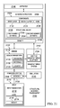
- Figures 1-17 may be combined with components in Figure 21 , used with components in Figure 21 , or a combination of the two. Additionally, some of the components in Figures 1-17 may be illustrative examples of how components shown in block form in Figure 21 can be implemented as physical structures.
- FIG. 22 an illustration of a flowchart of a process for manufacturing a sandwich structure is depicted in accordance with an illustrative embodiment.
- the process illustrated in Figure 22 may be implemented in structural sandwich environment 2100 in Figure 21 .
- one or more of the different operations may be implemented using manufacturing system 2142 or some other suitable component.
- the sandwich structure may be manufactured for use in a platform such as aircraft 100 in Figure 1 as well as other platforms.
- the process begins by attaching a first layer for a sandwich structure (operation 2200). The process then forms a cavity in a core of the sandwich structure (operation 2202). Thereafter, a structural insert is placed into the cavity (operation 2204).
- the second layer is then attached to at least one of the core or the structural insert after placing the structural insert into the cavity (operation 2206), with the process terminating thereafter.
- FIG. 23 an illustration of a flowchart of a process for designing a sandwich structure is depicted in accordance with an illustrative embodiment.
- the process illustrated in this flowchart may be implemented in designer 2106 in Figure 21 in one illustrative example.
- the process may be used to generate design 2102 for sandwich structure 2104 in the illustrative example.
- the process begins by receiving input for a sandwich structure (operation 2300).
- the process identifies input parameters from input for the sandwich structure (operation 2302).
- Input parameters may include, for example, a load that may be applied to the sandwich structure.
- the input parameters describing the load may describe the direction and magnitude of the load. Additionally, the parameters also may specify a desired weight for the sandwich structure for components in the sandwich structure.
- the process then generates design parameters for the sandwich structure (operation 2304).
- the design parameters may include, for example, dimensions, materials, and other parameters for sandwich structures. In particular, these parameters may describe components such as a first layer, a second layer, a core, and a structural insert in the sandwich structure.
- the process then stores the design parameters in a design (operation 2306).
- a simulation is then run using the design (operation 2308).
- a determination is made as to whether the design parameters in the design meets the input parameters (operation 2310). If the design parameters in the design meet the input parameters, the process terminates. Otherwise, adjustments are made to the design parameters (operation 2312), with the process then returning to operation 2308.
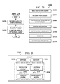
- FIG. 24 an illustration of a flowchart of a process for handling a load in an aircraft is depicted in accordance with an illustrative embodiment.
- the process illustrated in Figure 24 may be implemented in a sandwich structure, such as a honeycomb panel, in an aircraft such as aircraft 100 in Figure 1 .
- the process begins by receiving a load at a honeycomb panel (operation 2400).
- the honeycomb panel comprises a first skin, a second skin, a honeycomb core located between the first skin and the second skin, and a structural insert located in a cavity in the honeycomb core.
- the structural insert has a first number of parts configured to receive the load and a second number of parts.
- the process then spreads the load through a first number of parts in a structural insert (operation 2402), with the process turning thereafter.
- the load may be spread through the first number of parts such that the load spreads across the skin of the honeycomb panel.
- the skin may be the first skin or the second skin on either side of a core in the illustrative example.
- each block in the flowcharts or block diagrams may represent a module, a segment, a function, and/or a portion of an operation or step.
- one or more of the blocks may be implemented as program code, in hardware, or a combination of the program code and hardware.
- the hardware When implemented in hardware, the hardware may, for example, take the form of integrated circuits that are manufactured or configured to perform one or more operations in the flowcharts or block diagrams.
- the implementation may take the form of firmware.
- the function or functions noted in the blocks may occur out of the order noted in the figures.
- two blocks shown in succession may be executed substantially concurrently, or the blocks may sometimes be performed in the reverse order, depending upon the functionality involved.
- other blocks may be added in addition to the illustrated blocks in a flowchart or block diagram.
- the cavity formed in operation 2202 may be performed prior to or after attaching the core to the first layer in operation 2200.
- the process for generating and designing a honeycomb structure also may include operations in which simulations performed in adjustments are made to the design based on how the results of a simulation work.
- aircraft manufacturing and service method 2500 may be described in the context of aircraft manufacturing and service method 2500 as shown in Figure 25 and aircraft 2600 as shown in Figure 26 .
- Figure 25 an illustration of a block diagram of an aircraft manufacturing and service method is depicted in accordance with an illustrative embodiment.
- aircraft manufacturing and service method 2500 may include specification and design 2502 of aircraft 2600 in Figure 26 and material procurement 2504.
- aircraft 2600 in Figure 26 During production, component and subassembly manufacturing 2506 and system integration 2508 of aircraft 2600 in Figure 26 takes place. Thereafter, aircraft 2600 in Figure 26 may go through certification and delivery 2510 in order to be placed in service 2512. While in service 2512 by a customer, aircraft 2600 in Figure 26 is scheduled for routine maintenance and service 2514, which may include modification, reconfiguration, refurbishment, and other maintenance or service.
- Each of the processes of aircraft manufacturing and service method 2500 may be performed or carried out by a system integrator, a third party, and/or an operator.
- the operator may be a customer.
- a system integrator may include, without limitation, any number of aircraft manufacturers and major-system subcontractors
- a third party may include, without limitation, any number of vendors, subcontractors, and suppliers
- an operator may be an airline, a leasing company, a military entity, a service organization, and so on.
- aircraft 2600 is produced by aircraft manufacturing and service method 2500 in Figure 25 and may include airframe 2602 with plurality of systems 2604 and interior 2606.
- systems 2604 include one or more of propulsion system 2608, electrical system 2610, hydraulic system 2612, and environmental system 2614. Any number of other systems may be included.
- propulsion system 2608 includes one or more of propulsion system 2608, electrical system 2610, hydraulic system 2612, and environmental system 2614. Any number of other systems may be included.
- an aerospace example is shown, different illustrative embodiments may be applied to other industries, such as the automotive industry.
- Apparatuses and methods embodied herein may be employed during at least one of the stages of aircraft manufacturing and service method 2500 in Figure 25 .
- a sandwich structure with a structural insert in accordance with an illustrative embodiment may be manufactured during component and subassembly manufacturing 2506.
- the sandwich structure may be implemented in aircraft 2600 during system integration 2508.
- the sandwich structure with a structural insert in accordance with an illustrative embodiment may be implemented in aircraft 2600 during maintenance and service 2514.
- a sandwich structure may be used to replace other sandwich structures during routine maintenance, refurbishment, upgrades, or other operations performed during maintenance and service 2514.
- the use of a sandwich structure with a structural insert in accordance with an illustrative embodiment in aircraft 2600 while aircraft 2600 is in service 2512 may reduce the operating expenses for the aircraft.
- the reduction in weight may reduce fuel costs and may increase performance of aircraft 2600.
- One or more apparatus embodiments, method embodiments, or a combination thereof may be utilized while aircraft 2600 is in service 2512 and/or during maintenance and service 2514 in Figure 25 .
- the use of a number of the different illustrative embodiments may substantially expedite the assembly of and/or reduce the cost of aircraft 2600.
- one or more of the illustrative embodiments provide a method and apparatus for a sandwich structure to carry a load.
- the sandwich structure includes a structural insert configured to spread the load across the surface of the sandwich structure.
- the structural insert is comprised of two or more parts.
- the first number of parts is configured to receive a load. This first number of parts is also configured to spread the load.
- the second number of parts is configured to be assembled with the first number of parts to form the structural inserts.
- the different parts in the structural inserts may have a density that varies.
- the density may vary based on the type of material used, a density of holes, removal of material from areas in which a lower density is desired, or other suitable techniques. In this manner, the desired handling of a load may be achieved while reducing the weight of the sandwich structure.
Landscapes
- Engineering & Computer Science (AREA)
- Mechanical Engineering (AREA)
- Aviation & Aerospace Engineering (AREA)
- General Engineering & Computer Science (AREA)
- Chemical & Material Sciences (AREA)
- Composite Materials (AREA)
- Laminated Bodies (AREA)
- Panels For Use In Building Construction (AREA)
- Treatment Of Fiber Materials (AREA)
Abstract
Description
- The present disclosure relates generally to aircraft and, in particular, to structures in aircraft. Still more particularly, the present disclosure relates to a method and apparatus for structural inserts configured to receive loads in honeycomb structures in aircraft.
- Aircraft are being designed and manufactured with greater and greater percentages of composite materials. Composite materials are used in aircraft to decrease the weight of the aircraft. This decreased weight improves performance features such as payload capacities and fuel efficiencies. Further, composite materials provide longer service life for various components in an aircraft.
- Composite materials are tough, light-weight materials created by combining two or more functional components. For example, a composite material may include reinforcing fibers bound in a polymer resin matrix. As another example, honeycomb structures are a class of composite materials. A honeycomb structure may be a honeycomb sandwich structure. With this type of structure, two layers are attached on either side of a core. These layers may be considered a skin for the honeycomb sandwich structure. A honeycomb sandwich structure typically has a honeycomb structure.
- With this type of structure, a desired level of bending stiffness may be achieved with a lower density as compared to a structure that uses a solid core or one comprised of a solid panel. The lower density may result in a desired weight savings for an aircraft.
- These honeycomb sandwich structures, however, may not carry loads in a desired manner when loads are applied to one of the skins of these honeycomb sandwich structures. One manner in which additional loadbearing capability may be provided for a honeycomb sandwich structure is through the use of a potted core.
- Potting a honeycomb core is a process in which open areas in the honeycomb core are filled with a material. This material may be a potting material or compound such as a resin.
- Introducing a potting material into a honeycomb core, however, may be more time-consuming than desired. For example, a potting material may be placed into the core and cured. Additional potting material is placed into the core and cured. Thereafter, the excess material may be removed through sanding, machining, or other processes. In some cases, additional material may be introduced after the sanding or machining.
- This type of process may be more time-consuming and expensive than desired. Further, the use of a potting material also may result in more weight than desired. Therefore, it would be desirable to have a method and apparatus that take into account at least some of the issues discussed above, as well as other possible issues.
- In one illustrative embodiment, an apparatus comprises a first number of parts and a second number of parts. The first number of parts is configured to receive a load. The second number of parts is configured to be assembled with the first number of parts to form a structural insert for a sandwich structure.
- In another illustrative embodiment, a honeycomb panel comprises a first skin, a second skin, a honeycomb core, and a structural insert. The honeycomb core is located between the first skin and the second skin. The structural insert is located in a cavity in the honeycomb core. The structural insert has a first number of parts configured to receive a load and a second number of parts.
- In yet another illustrative embodiment, a method for manufacturing a sandwich structure is provided. A cavity is formed in a core of the sandwich structure. A structural insert is placed into the cavity. The structural insert comprises a first number of parts configured to receive a load and a second number of parts assembled with the first number of parts to form the structural insert.
- In still another illustrative embodiment, a method for handling a load in an aircraft is provided. The load is received at a honeycomb panel. The honeycomb panel comprises a first skin, a second skin, a honeycomb core, and a structural insert. The honeycomb core is located between the first skin and the second skin. The structural insert is located in a cavity in the honeycomb core. The structural insert has a first number of parts configured to receive the load and a second number of parts. The load is spread through the first number of parts in the structural insert.
- The features and functions can be achieved independently in various embodiments of the present disclosure or may be combined in yet other embodiments in which further details can be seen with reference to the following description and drawings.
- The novel features believed characteristic of the illustrative embodiments are set forth in the appended claims. The illustrative embodiments, however, as well as a preferred mode of use, further objectives and features thereof, will best be understood by reference to the following detailed description of an illustrative embodiment of the present disclosure when read in conjunction with the accompanying drawings, wherein:
-
Figure 1 is an illustration of an aircraft in accordance with an illustrative embodiment; -
Figure 2 is a more detailed illustration of a section of a floor in an aircraft in accordance with an illustrative embodiment; -
Figure 3 is an illustration of a honeycomb sandwich structure in accordance with an illustrative embodiment; -
Figure 4 is an illustration of a cross-sectional view of a sandwich structure in accordance with an illustrative embodiment; -
Figure 5 is an illustration of an exploded view of a sandwich structure in accordance with an illustrative embodiment; -
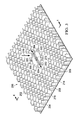
Figure 6 is an illustration of a sandwich structure with a structural insert in accordance with an illustrative embodiment; -
Figure 7 is an illustration of a cross-sectional view of a sandwich structure in accordance with an illustrative embodiment; -
Figure 8 is an illustration of an exploded view of a sandwich structure in accordance with an illustrative embodiment; -
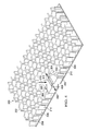
Figure 9 is an illustration of a sandwich structure with a structural insert in accordance with an illustrative embodiment; -
Figure 10 is an illustration of a cross-sectional view of a sandwich structure in accordance with an illustrative embodiment; -
Figure 11 is an illustration of an exploded view of a sandwich structure in accordance with an illustrative embodiment; -
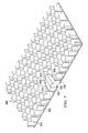
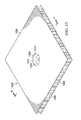
Figure 12 is an illustration of a sandwich structure with a structural insert in accordance with an illustrative embodiment; -
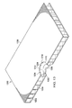
Figure 13 is an illustration of a cross-sectional view of a sandwich structure in accordance with an illustrative embodiment; -
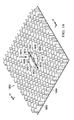
Figure 14 is an illustration of an exploded view of a sandwich structure in accordance with an illustrative embodiment; -
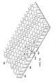
Figure 15 is an illustration of a sandwich structure with a structural insert in accordance with an illustrative embodiment; -
Figure 16 is an illustration of a cross-sectional view of a sandwich structure in accordance with an illustrative embodiment; -
Figure 17 is an illustration of an exploded view of a sandwich structure in accordance with an illustrative embodiment; -
Figure 18 is an illustration of a sandwich structure with a structural insert in accordance with an illustrative embodiment; -
Figure 19 is an illustration of a cross-sectional view of a sandwich structure in accordance with an illustrative embodiment; -
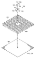
Figure 20 is an illustration of an exploded view of a sandwich structure in accordance with an illustrative embodiment; -
Figure 21 is an illustration of a block diagram of a structural sandwich environment in accordance with an illustrative embodiment; -
Figure 22 is an illustration of a flowchart of a process for manufacturing a sandwich structure in accordance with an illustrative embodiment; -
Figure 23 is an illustration of a flowchart of a process for designing a sandwich structure in accordance with an illustrative embodiment; -
Figure 24 is an illustration of a flowchart of a process for handling a load in an aircraft in accordance with an illustrative embodiment; -
Figure 25 is an illustration of a block diagram of an aircraft manufacturing and service method in accordance with an illustrative embodiment; and -
Figure 26 is an illustration of a block diagram of an aircraft in which an illustrative embodiment may be implemented. - The illustrative embodiments recognize and take into account one or more different considerations. For example, the illustrative embodiments recognize and take into account that one alternative to filling the honeycomb structure with a resin, such as potting, may be the use of inserts. For example, the illustrative embodiments recognize and take into account that a composite insert may be placed into an area of a honeycomb sandwich panel to receive a load.
- The illustrative embodiments recognize and take into account, however, that with using a solid insert, the amount of weight of the honeycomb sandwich panel may be greater than desired. This situation may reduce the fuel efficiency for performance of an aircraft.
- The illustrative embodiments recognize and take into account that with the use of rapid prototyping systems, a customized structural insert may be designed and manufactured for use in a honeycomb sandwich panel that results in less weight. For example, different parts may be manufactured using an additive manufacturing process. These parts may be assembled to form the structural inserts that receive a load in a desired manner for the honeycomb sandwich panel. This type of process is more precise as compared to filling portions of a honeycomb structure with a resin or other type of potting material.
- Thus, in one illustrative embodiment, an apparatus comprises a first number of parts configured to receive a load and a second number of parts configured to be assembled with the first number of parts to form a structural insert for a sandwich structure.
- With reference now to the figures, and in particular, with reference to
Figure 1 , an illustration of an aircraft is depicted in accordance with an illustrative embodiment. In this illustrative example,aircraft 100 haswing 102 andwing 104 attached tobody 106.Aircraft 100 includesengine 108 attached towing 102 andengine 110 attached towing 104. -
Body 106 hasnose section 112 andtail section 114.Horizontal stabilizer 116,horizontal stabilizer 118, andvertical stabilizer 120 are attached totail section 114 ofbody 106. -
Aircraft 100 is an example of an aircraft in which a sandwich structure may be implemented in accordance with an illustrative embodiment. For example, an illustrative embodiment may be implemented ininterior 122 ofaircraft 100. For example, sandwich structures may be implemented in various parts such ascloset 124,wall 126, andfloor 128, as well as in other parts or monuments that may be present ininterior 122 ofaircraft 100. A more detailed illustration ofsection 130 offloor 128 is described below. - The illustration of
aircraft 100 is not meant to limit the manner in which different illustrative embodiments may be implemented. For example, an illustrative embodiment may be implemented platforms other thanaircraft 100. The platform may be, for example, a mobile platform, a stationary platform, a land-based structure, an aquatic-based structure, and a space-based structure. More specifically, the platform, may be a surface ship, a tank, a personnel carrier, a train, a spacecraft, a space station, a satellite, a submarine, an automobile, a power plant, a bridge, a dam, a house, a manufacturing facility, a building, or some other suitable type of platform. - With reference next to
Figure 2 , a more detailed illustration of a section of a floor in an aircraft is depicted in accordance with an illustrative embodiment. As depicted, a more detailed view ofsection 130 offloor 128 inaircraft 100 inFigure 1 is shown. - In this illustrative example,
sandwich structure 200 takes the form ofhoneycomb sandwich panel 202. As shown in this example,honeycomb sandwich panel 202 is comprised offirst layer 204,second layer 206, andcore 208. - In the illustrative example,
core 208 is located betweenfirst layer 204 andsecond layer 206. As depicted,core 208 is attached tofirst layer 204 andsecond layer 206. -
First layer 204 formsfirst skin 210 andsecond layer 206 formssecond skin 212 forhoneycomb sandwich panel 202.Core 208 takes the form ofhoneycomb core 214 in this particular example. - As depicted,
honeycomb sandwich panel 202 hashole 216.Hole 216 inhoneycomb sandwich panel 202 may receive a fastener (not shown) to attachhoneycomb sandwich panel 202 to another structure (not shown) inaircraft 100. This attachment may result in the application of a load to honeycombsandwich panel 202 during operation ofaircraft 100. - Turning next to
Figure 3 , an illustration of a honeycomb sandwich structure is depicted in accordance with an illustrative embodiment. As depicted, an exposed view ofsandwich structure 200 is shown. In this view,second layer 206 has been removed from view. - As can be seen in this exposed view,
structural insert 300 is located incavity 302 ofcore 208 insandwich structure 200.Cavity 302 is configured to receivestructural insert 300. - As depicted,
structural insert 300 has a circular cross section and is comprised of first number ofparts 304 and second number ofparts 306. Second number ofparts 306 is configured to be assembled with first number ofparts 304 to formstructural insert 300 insandwich structure 200. As used herein, "a number of," used with reference to items, means one or more items. For example, first number ofparts 304 means one or more parts. - In the illustrative example,
structural insert 300 is configured to spread a load across a surface ofstructural insert 300. For example, the load may be spread acrosssurface 308 offirst layer 204 insandwich structure 200. As depicted, first number ofparts 304 instructural insert 300 is configured to receive the load. Withoutstructural insert 300, the configuration ofsandwich structure 200 may be less efficient with respect to spreading a load acrosssurface 308 ofsandwich structure 200. - In these illustrative examples, first number of
parts 304, second number ofparts 306, or both may be manufactured using an additive manufacturing process. The additive manufacturing process may be, for example, three dimensional printing. A design of an object made using software, such as a computer-aided design (CAD) program or some other suitable software, may then be used to print the object. - In this particular example, first number of
parts 304 has a shape that is configured to spread a load applied tostructural insert 300. For example, the load may be applied in the direction ofarrow 310, which is substantially perpendicular tocore 208. The load may be spread in the direction ofarrow 312 in the illustrative example. In other illustrative examples, the load may be applied from the opposite side shown with respect toarrow 310. In other illustrative examples, the load may be applied in other directions other than with respect toarrow 310. - Turning next to
Figure 4 , an illustration of a cross-sectional view of a sandwich structure is depicted in accordance with an illustrative embodiment. A cross-sectional view ofsandwich structure 200 is seen taken along lines 4-4 inFigure 3 . - In this view, first number of
parts 304 includespart 400. Second number ofparts 306 includespart 402 andpart 404. In this illustrative example,part 400 fits in betweenpart 402 andpart 404.Part 400,part 402, andpart 404 are located incavity 302 incore 208. For example, these parts may be placed intocavity 302 already assembled in the desired arrangement. In other illustrative examples, the parts may be assembled prior to being placed intocavity 302. - Turning next to
Figure 5 , an illustration of an exploded view of a sandwich structure is depicted in accordance with an illustrative embodiment. In this figure, an exploded view ofsandwich structure 200 inFigure 2 is shown. - As depicted,
first layer 204 andsecond layer 206 may be comprised of aluminum.Honeycomb core 214 may be comprised of fiberglass. First number ofparts 304 instructural insert 300 may be comprised of graphite. Second number ofparts 306 instructural insert 300 may be comprised of a composite material. - As depicted,
first layer 204 hasthickness 500,second layer 206 hasthickness 502, andhoneycomb core 214 hasthickness 504. In this illustrative example,structural insert 300 hasdiameter 506 andthickness 508. - In this illustrative example, these various dimensions may vary depending on the particular implementation. As shown,
thickness 500 is about 0.1 inches,thickness 502 is about 0.1 inches, andthickness 504 is about 1.0 inches.Diameter 506 is about 3.0 inches andthickness 508 is about 1.0 inches. - With reference now to
Figure 6 , an illustration of a sandwich structure with a structural insert is depicted in accordance with an illustrative embodiment. In this depicted example, an exposed view ofsandwich structure 600 is depicted.Sandwich structure 600 is another illustrative example of a sandwich structure that may be used insection 130 offloor 128 inaircraft 100 inFigure 1 . - As depicted in this exposed view,
sandwich structure 600 includesfirst layer 602,core 604, andstructural insert 606. A second layer forsandwich structure 600 is not shown in this exposed view. - In this illustrative example,
structural insert 606 is located incavity 608 incore 604 ofsandwich structure 600. As depicted,structural insert 606 has an ellipsoid cross section. -
Structural insert 606 is comprised of first number ofparts 610 and second number ofparts 612. First number ofparts 610 is configured to receive a load that may be applied tosandwich structure 600. - With reference next to
Figure 7 , an illustration of a cross-sectional view of a sandwich structure is depicted in accordance with an illustrative embodiment. A cross-sectional view ofsandwich structure 600 is seen taken along lines 7-7 inFigure 6 . - In this view, first number of
parts 610 includespart 700. Second number ofparts 612 includespart 702 andpart 704. - Turning next to
Figure 8 , an illustration of an exploded view of a sandwich structure is depicted in accordance with an illustrative embodiment. In this figure, an exploded view ofsandwich structure 600 inFigure 6 is shown. - With reference now to
Figure 9 , an illustration of a sandwich structure with a structural insert is depicted in accordance with an illustrative embodiment. In this depicted example, an exposed view ofsandwich structure 900 is depicted. As depicted,sandwich structure 900 is yet another illustrative example of a sandwich structure that may be used insection 130 offloor 128 inaircraft 100 inFigure 1 . - In this exposed view,
sandwich structure 900 includesfirst layer 902,core 904, andstructural insert 906. The second layer forsandwich structure 900 is not shown in this exposed view. - In this illustrative example,
structural insert 906 is located incavity 908 incore 904 ofsandwich structure 900. As depicted,structural insert 906 has a circular cross-section. -
Structural insert 906 is comprised of first number ofparts 910 and second number ofparts 912. First number ofparts 910 is configured to receive a load that may be applied tosandwich structure 900. - With reference next to
Figure 10 , an illustration of a cross-sectional view of a sandwich structure is depicted in accordance with an illustrative embodiment. A cross-sectional view ofsandwich structure 900 is seen taken along lines 10-10 inFigure 9 . - In this view, first number of
parts 910 includespart 1000. Second number ofparts 912 includespart 1002. As depicted,part 1000 is configured to be placed withinpart 1002. In this illustrative example, this assembly ofpart 1000 inpart 1002 formsstructural insert 906. - Turning next to
Figure 11 , an illustration of an exploded view of a sandwich structure is depicted in accordance with an illustrative embodiment. In this figure, an exploded view ofsandwich structure 900 inFigure 9 is shown. - With reference next to
Figure 12 , an illustration of a sandwich structure with a structural insert is depicted in accordance with an illustrative embodiment. In this depicted example, a view ofsandwich structure 1200 is depicted. As depicted,sandwich structure 1200 is another illustrative example of a sandwich structure that may be used insection 130 offloor 128 inaircraft 100 inFigure 1 . - In this view,
sandwich structure 1200 includesfirst layer 1202,core 1204,second layer 1206, andstructural insert 1208. As depicted,structural insert 1208 is located incavity 1210 incore 1204 ofsandwich structure 1200. As depicted,structural insert 1208 has a circular cross-section. -
Structural insert 1208 is comprised of first number ofparts 1212 and second number ofparts 1214. First number ofparts 1212 is configured to receive a load that may be applied tosandwich structure 1200. - In
Figure 13 , an illustration of a cross-sectional view of a sandwich structure is depicted in accordance with an illustrative embodiment. A cross-sectional view ofsandwich structure 1200 is seen taken along lines 13-13 inFigure 12 . - In this depicted view, first number of
parts 1212 includespart 1300. Second number ofparts 1214 includespart 1302 andpart 1304. As can be seen,part 1300 is configured to be placed betweenpart 1302 andpart 1304. For example,part 1300 may be placed onpart 1302. Thereafter,part 1304 may be placed overpart 1302. This assembly ofpart 1304 andpart 1302 is to holdpart 1300 in place in the assembly that formsstructural insert 1208. - Turning to
Figure 14 , an illustration of an exploded view of a sandwich structure is depicted in accordance with an illustrative embodiment. In this figure, an exploded view ofsandwich structure 1200 inFigure 12 is shown. - With reference next to
Figure 15 , an illustration of a sandwich structure with a structural insert is depicted in accordance with an illustrative embodiment. In this depicted example, an exposed view ofsandwich structure 1500 is depicted.Sandwich structure 1500 is another illustrative example of a sandwich structure that may be used insection 130 offloor 128 inaircraft 100 in Figure +1. - As depicted in this exposed view,
sandwich structure 1500 includesfirst layer 1502,core 1504, andstructural insert 1506. A second layer forsandwich structure 1500 is not shown in this exposed view. - In this illustrative example,
structural insert 1506 is located incavity 1508 incore 1504 ofsandwich structure 1500. As depicted,structural insert 1506 has a square cross-section. -
Structural insert 1506 is comprised of first number ofparts 1510 and second number ofparts 1512. First number ofparts 1510 is configured to receive a load that may be applied tosandwich structure 1500. - With reference now to
Figure 16 , an illustration of a cross-sectional view of a sandwich structure is depicted in accordance with an illustrative embodiment. A cross-sectional view ofsandwich structure 1500 is seen taken along lines 16-16 inFigure 15 . - In this cross-sectional view, first number of
parts 1510 includespart 1600. Second number ofparts 1512 includespart 1602,part 1604,part 1606, andpart 1608. - Turning next to
Figure 17 , an illustration of an exploded view of a sandwich structure is depicted in accordance with an illustrative embodiment. In this figure, an exploded view ofsandwich structure 1500 inFigure 15 is shown. - With reference now to
Figure 18 , an illustration of a sandwich structure with a structural insert is depicted in accordance with an illustrative embodiment. In this depicted example, an exposed view ofsandwich structure 1800 is depicted. As depicted,sandwich structure 1800 is still yet another illustrative example of a sandwich structure that may be used insection 130 offloor 128 inaircraft 100 inFigure 1 . - In this exposed view,
sandwich structure 1800 includesfirst layer 1802,core 1804, andstructural insert 1806. The second layer forsandwich structure 1800 is not shown in this exposed view. - In this illustrative example,
structural insert 1806 is located incavity 1808 incore 1804 ofsandwich structure 1800. As depicted,structural insert 1806 has a circular cross-section. -
Structural insert 1806 is comprised of first number ofparts 1810 and second number ofparts 1812. First number ofparts 1810 is configured to receive a load that may be applied tosandwich structure 1800. - As depicted, first number of
parts 1810 has a shape that is configured to spread a load applied tostructural insert 1806. For example, the load may be applied in the direction ofarrow 1814 atcenter 1816 ofstructural insert 1806, which is substantially perpendicular tocore 1804. The load may be spread in the direction ofarrow 1818 in the illustrative example. - In this illustrative example, the load is at a maximum near
center 1816 ofstructural insert 1806 and then may decrease in the direction ofarrow 1818 fromcenter point 1819. Similarly, first number ofparts 1810 has a shape that decreases in thickness in the direction ofarrow 1818. The shape of first number ofparts 1810, therefore, provides the greatest structural support nearcenter 1816 ofstructural insert 1806 where the load is at a maximum and there is less structural support as the thickness of first number ofparts 1810 decreases in the direction ofarrow 1818. The shape of first number ofparts 1810 may provide an increased weight savings while still providing sufficient structural support. - Additionally, first number of
parts 1810 may havepart 1820 andpart 1822.Part 1820 andpart 1822 are semicircular cutouts in this depicted example. In other illustrative examples,part 1820 andpart 1822 may have a shape selected from one of a parabola, a triangle, an arc, or other shapes.Part 1820 andpart 1822 remove material from first number ofparts 1810 that may not be needed to distribute the load applied tostructural insert 1806. In this manner, the density of first number ofparts 1810 is changed to create a configuration that results in decreased weight ofstructural insert 1806. In other illustrative examples, the density of first number ofparts 1810 may be changed by drilling holes, removing material, combining different materials, or other techniques. - With reference next to
Figure 19 , an illustration of a cross-sectional view of a sandwich structure is depicted in accordance with an illustrative embodiment. A cross-sectional view ofsandwich structure 1800 is seen taken along lines 19-19 inFigure 18 . - In this view, first number of
parts 1810 includespart 1900. Second number ofparts 1812 includespart 1902 andpart 1904. - Turning next to
Figure 20 , an illustration of an exploded view of a sandwich structure is depicted in accordance with an illustrative embodiment. In this figure, an exploded view ofsandwich structure 1800 inFigure 18 is shown. - The different illustrations of a sandwich structure with a structural insert in
Figures 2-17 are only presented as illustrative examples of some implementations for a sandwich structure and a structural insert. These illustrations are not meant to limit the manner in which other illustrative embodiments may be implemented. - For example, although the sandwich structure has been depicted as having a first layer and a second layer with a core between the layers, the sandwich structure may have other configurations. For example, two layers may be present on either side of the core rather than just one layer as shown. Further, the layers may be formed from the same type of material or different types of materials. In other words, the first layer may be comprised of the same material as the second layer or different materials from the second layer.
- As another example, although the sandwich structures are shown as being planar, sandwich structures may have other shapes. For example, sandwich structures may be curved rather than planar as depicted in these illustrative examples.
- In still another illustrative example, one or more structural inserts may be used in addition to the structural inserts in the different illustrations. Further, although the structural insert is shown as being centrally located in the sandwich structure, the structural inserts may be placed in other locations in the sandwich structure.
- Further, the different structural inserts may have shapes other than those depicted. For example, the structural concerts may have an excitable cross-section, an irregular cross section, or some other suitable shape. In still other illustrative examples, the structural inserts may have other forms such as a sphere, a frustrum, or other types of volumes.
- With reference now to
Figure 21 , an illustration of a block diagram of a structural sandwich design environment is depicted in accordance with an illustrative embodiment. As depicted,structural sandwich environment 2100 is configured to generatedesign 2102 forsandwich structure 2104 and also may be used to manufacturesandwich structure 2104. - In the illustrative example,
designer 2106 is configured to generatedesign 2102 and may be implemented in software, hardware, firmware or a combination thereof. When software is used, the operations performed bydesigner 2106 may be implemented in program code configured to run on a processor unit. When firmware is used, the operations performed bydesigner 2106 may be implemented in program code and data and stored in persistent memory to run on a processor unit. When hardware is employed, the hardware may include circuits that operate to perform the operations indesigner 2106. - In the illustrative examples, the hardware may take the form of a circuit system, an integrated circuit, an application specific integrated circuit (ASIC), a programmable logic device, or some other suitable type of hardware configured to perform a number of operations. With a programmable logic device, the device may be configured to perform the number of operations. The device may be reconfigured at a later time or may be permanently configured to perform the number of operations. Examples of programmable logic devices include, for example, a programmable logic array, a programmable array logic, a field programmable logic array, a field programmable gate array, and other suitable hardware devices. Additionally, the processes may be implemented in organic components integrated with inorganic components and/or may be comprised entirely of organic components excluding a human being. For example, the processes may be implemented as circuits in organic semiconductors.
- In this illustrative example,
designer 2106 is located incomputer system 2108.Computer system 2108 is comprised of a number of computers. When more than one computer is present incomputer system 2108, those computers may communicate with each other through a communications medium such as a network. - As depicted,
designer 2106 may receiveinput 2110 for use in generatingdesign 2102 forsandwich structure 2104. For example,input 2110 may includeinput parameters 2112.Input parameters 2112 may describe, for example,load 2114,weight 2116, and other suitable parameters. - In the illustrative example,
load 2114 is one or more forces, formations, accelerations, or some combination thereof applied tosandwich structure 2104.Load 2114 may be caused by another structure.Input parameters 2112 forload 2114 may include a direction of the force, the magnitude of the force, and other suitable factors. The direction of the force may, for example, describe at least one of the spreading or desired spreading of the force onsandwich structure 2104. - Using
input 2110,designer 2106 is configured to generatedesign 2102. In particular,designer 2106 may generatedesign parameters 2118 forsandwich structure 2104. - As depicted,
design parameters 2118 may include various parameters. For example,design parameters 2118 may describecomponents 2120 insandwich structure 2104.Components 2120 may include, for example, at least one offirst layer 2122,second layer 2124,core 2126, andstructural insert 2128 insandwich structure 2104. - In the illustrative example,
design parameters 2118 may include at least one ofdimensions 2130,materials 2132,location 2133, or other suitable parameters to describe the various components insandwich structure 2104. - For example,
dimensions 2130 andmaterials 2132 may be used to customizestructural insert 2128 in a manner that meetsweight 2116 that may be desired forsandwich structure 2104 to carryload 2114 as specified ininput 2110. For example,dimensions 2130 andmaterials 2132 may be used to describe first number ofparts 2134 and second number ofparts 2136 instructural insert 2128. - In the illustrative examples,
dimensions 2130 may take various forms. These forms may include those for the illustrative examples depicted inFigures 2-21 . -
Materials 2132 for first number ofparts 2134 and second number ofparts 2136 may be comprised of a number of materials selected from at least one of a composite material, a metal, aluminum, titanium, graphite, plastic, polycarbonate, glass, fiberglass, wood, concrete, steel, carbon fiber, para-aramid synthetic fiber, a carbon fiber reinforced thermoplastic, a carbon fiber thermoset polymer, or other suitable materials. The selection ofmaterials 2132 also may be used to generatedensity 2138 for at least one of first number ofparts 2134 or second number ofparts 2136. -
Dimensions 2130 may also include an identification of holes or other features that may be used to changedensity 2138 for at least one of first number ofparts 2134 or second number ofparts 2136. For example,dimensions 2130 may include identification of holes, voids, or other features that may be desirable to changedensity 2138. As a result,density 2138 for first number ofparts 2134 may be different over different portions of first number ofparts 2134 based on the load expected to be placed on or received bystructural insert 2128 as specified byload 2114 ininput 2110. - The changes or selection of
density 2138 for different parts ofstructural insert 2128 may be used to reachweight 2116 forload 2114 at a specifiedinput 2110. In this manner, weight savings may be achieved while providing the handling on processing of loads in a desired manner. - Further,
dimensions 2130 andmaterials 2132 also may describe at least one offirst layer 2122,second layer 2124, orcore 2126. In the illustrative examples,first layer 2122 andsecond layer 2124 may be a number of layers of laminate comprising materials selected from of least one of steel, aluminum, a composite material, fiberglass, or carbon fiber. - In these illustrative examples,
materials 2132 for at least one offirst layer 2122 orsecond layer 2124 may be selected from of least one of steel, aluminum, a composite material, fiberglass, or carbon fiber. -
Materials 2132 forcore 2126 may be selected from at least one of fiberglass, paper, cardboard, wood, foam, steel, a composite material, a carbon fiber infused resin, or other suitable materials. The material selected may be based on the type of core used forcore 2126. For example,core 2126 may be selected from one of a foam core, a honeycomb core, a composite core, or some other suitable type of core. - In this illustrative example,
location 2133 describes the location ofstructural insert 2128 insandwich structure 2104.Location 2133 may be identified frominput 2110. For example,load 2114 may describe the location where a force may be applied tosandwich structure 2104. The location of the force may be used to identifylocation 2133 forstructural insert 2128. - With
design 2102,designer 2106 may runsimulation 2140 forsandwich structure 2104. Based on the results ofsimulation 2140, adjustments may be made to design 2102 as needed to reach or meetinput parameters 2112 ininput 2110. - Additionally,
design 2102 may be used bymanufacturing system 2142 to manufacturesandwich structure 2104. In particular, at least one of first number ofparts 2134 or second number ofparts 2136 may be manufactured usingadditive manufacturing equipment 2144 inmanufacturing system 2142. - With
first layer 2122,second layer 2124,core 2126, first number ofparts 2134 and second number ofparts 2136,operator 2146 may assemblesandwich structure 2104.Operator 2146 may be, for example, a human operator or a robotic operator. - The illustration of
structural sandwich environment 2100 inFigure 21 is not meant to imply physical or architectural limitations to the manner in which an illustrative embodiment may be implemented. Other components in addition to or in place of the ones illustrated may be used. Some components may be unnecessary. Also, the blocks are presented to illustrate some functional components. One or more of these blocks may be combined, divided, or combined and divided into different blocks when implemented in an illustrative embodiment. - For example, other types of manufacturing equipment may be used in place of or in addition to
additive manufacturing equipment 2144. For example, molding equipment, composite manufacturing equipment, lathes, water jets, lasers, and other suitable types of equipment may be used to manufacture first number ofparts 2134 and second number ofparts 2136 instructural insert 2128. - Additionally, the different components shown in
Figures 1-17 may be combined with components inFigure 21 , used with components inFigure 21 , or a combination of the two. Additionally, some of the components inFigures 1-17 may be illustrative examples of how components shown in block form inFigure 21 can be implemented as physical structures. - With reference next to
Figure 22 , an illustration of a flowchart of a process for manufacturing a sandwich structure is depicted in accordance with an illustrative embodiment. The process illustrated inFigure 22 may be implemented instructural sandwich environment 2100 inFigure 21 . In particular, one or more of the different operations may be implemented usingmanufacturing system 2142 or some other suitable component. The sandwich structure may be manufactured for use in a platform such asaircraft 100 inFigure 1 as well as other platforms. - The process begins by attaching a first layer for a sandwich structure (operation 2200). The process then forms a cavity in a core of the sandwich structure (operation 2202). Thereafter, a structural insert is placed into the cavity (operation 2204).
- The second layer is then attached to at least one of the core or the structural insert after placing the structural insert into the cavity (operation 2206), with the process terminating thereafter.
- With reference next to
Figure 23 , an illustration of a flowchart of a process for designing a sandwich structure is depicted in accordance with an illustrative embodiment. The process illustrated in this flowchart may be implemented indesigner 2106 inFigure 21 in one illustrative example. The process may be used to generatedesign 2102 forsandwich structure 2104 in the illustrative example. - The process begins by receiving input for a sandwich structure (operation 2300). The process identifies input parameters from input for the sandwich structure (operation 2302). Input parameters may include, for example, a load that may be applied to the sandwich structure. The input parameters describing the load may describe the direction and magnitude of the load. Additionally, the parameters also may specify a desired weight for the sandwich structure for components in the sandwich structure.
- The process then generates design parameters for the sandwich structure (operation 2304). The design parameters may include, for example, dimensions, materials, and other parameters for sandwich structures. In particular, these parameters may describe components such as a first layer, a second layer, a core, and a structural insert in the sandwich structure. The process then stores the design parameters in a design (operation 2306).
- A simulation is then run using the design (operation 2308). Next, a determination is made as to whether the design parameters in the design meets the input parameters (operation 2310). If the design parameters in the design meet the input parameters, the process terminates. Otherwise, adjustments are made to the design parameters (operation 2312), with the process then returning to
operation 2308. - Turning now to
Figure 24 , an illustration of a flowchart of a process for handling a load in an aircraft is depicted in accordance with an illustrative embodiment. The process illustrated inFigure 24 may be implemented in a sandwich structure, such as a honeycomb panel, in an aircraft such asaircraft 100 inFigure 1 . - The process begins by receiving a load at a honeycomb panel (operation 2400). In this illustrative example, the honeycomb panel comprises a first skin, a second skin, a honeycomb core located between the first skin and the second skin, and a structural insert located in a cavity in the honeycomb core. The structural insert has a first number of parts configured to receive the load and a second number of parts.
- The process then spreads the load through a first number of parts in a structural insert (operation 2402), with the process turning thereafter. In the illustrative example, the load may be spread through the first number of parts such that the load spreads across the skin of the honeycomb panel. The skin may be the first skin or the second skin on either side of a core in the illustrative example.
- The flowcharts and block diagrams in the different depicted embodiments illustrate the architecture, functionality, and operation of some possible implementations of apparatuses and methods in an illustrative embodiment. In this regard, each block in the flowcharts or block diagrams may represent a module, a segment, a function, and/or a portion of an operation or step. For example, one or more of the blocks may be implemented as program code, in hardware, or a combination of the program code and hardware. When implemented in hardware, the hardware may, for example, take the form of integrated circuits that are manufactured or configured to perform one or more operations in the flowcharts or block diagrams. When implemented as a combination of program code and hardware, the implementation may take the form of firmware.
- In some alternative implementations of an illustrative embodiment, the function or functions noted in the blocks may occur out of the order noted in the figures. For example, in some cases, two blocks shown in succession may be executed substantially concurrently, or the blocks may sometimes be performed in the reverse order, depending upon the functionality involved. Also, other blocks may be added in addition to the illustrated blocks in a flowchart or block diagram.
- For example, the cavity formed in
operation 2202 may be performed prior to or after attaching the core to the first layer inoperation 2200. As another example, the process for generating and designing a honeycomb structure also may include operations in which simulations performed in adjustments are made to the design based on how the results of a simulation work. - Illustrative embodiments of the disclosure may be described in the context of aircraft manufacturing and
service method 2500 as shown inFigure 25 andaircraft 2600 as shown inFigure 26 . Turning first toFigure 25 , an illustration of a block diagram of an aircraft manufacturing and service method is depicted in accordance with an illustrative embodiment. During pre-production, aircraft manufacturing andservice method 2500 may include specification anddesign 2502 ofaircraft 2600 inFigure 26 andmaterial procurement 2504. - During production, component and
subassembly manufacturing 2506 andsystem integration 2508 ofaircraft 2600 inFigure 26 takes place. Thereafter,aircraft 2600 inFigure 26 may go through certification anddelivery 2510 in order to be placed inservice 2512. While inservice 2512 by a customer,aircraft 2600 inFigure 26 is scheduled for routine maintenance andservice 2514, which may include modification, reconfiguration, refurbishment, and other maintenance or service. - Each of the processes of aircraft manufacturing and
service method 2500 may be performed or carried out by a system integrator, a third party, and/or an operator. In these examples, the operator may be a customer. For the purposes of this description, a system integrator may include, without limitation, any number of aircraft manufacturers and major-system subcontractors; a third party may include, without limitation, any number of vendors, subcontractors, and suppliers; and an operator may be an airline, a leasing company, a military entity, a service organization, and so on. - With reference now to
Figure 26 , an illustration of a block diagram of an aircraft is depicted in which an illustrative embodiment may be implemented. In this example,aircraft 2600 is produced by aircraft manufacturing andservice method 2500 inFigure 25 and may includeairframe 2602 with plurality ofsystems 2604 and interior 2606. Examples ofsystems 2604 include one or more ofpropulsion system 2608,electrical system 2610,hydraulic system 2612, andenvironmental system 2614. Any number of other systems may be included. Although an aerospace example is shown, different illustrative embodiments may be applied to other industries, such as the automotive industry. - Apparatuses and methods embodied herein may be employed during at least one of the stages of aircraft manufacturing and
service method 2500 inFigure 25 . For example, a sandwich structure with a structural insert in accordance with an illustrative embodiment may be manufactured during component andsubassembly manufacturing 2506. The sandwich structure may be implemented inaircraft 2600 duringsystem integration 2508. Further, the sandwich structure with a structural insert in accordance with an illustrative embodiment may be implemented inaircraft 2600 during maintenance andservice 2514. For example, a sandwich structure may be used to replace other sandwich structures during routine maintenance, refurbishment, upgrades, or other operations performed during maintenance andservice 2514. As another example, the use of a sandwich structure with a structural insert in accordance with an illustrative embodiment inaircraft 2600 whileaircraft 2600 is inservice 2512 may reduce the operating expenses for the aircraft. For example, the reduction in weight may reduce fuel costs and may increase performance ofaircraft 2600. - One or more apparatus embodiments, method embodiments, or a combination thereof may be utilized while
aircraft 2600 is inservice 2512 and/or during maintenance andservice 2514 inFigure 25 . The use of a number of the different illustrative embodiments may substantially expedite the assembly of and/or reduce the cost ofaircraft 2600. - Thus, one or more of the illustrative embodiments provide a method and apparatus for a sandwich structure to carry a load. In one illustrative embodiment, the sandwich structure includes a structural insert configured to spread the load across the surface of the sandwich structure.
- In the illustrative examples, the structural insert is comprised of two or more parts. The first number of parts is configured to receive a load. This first number of parts is also configured to spread the load. The second number of parts is configured to be assembled with the first number of parts to form the structural inserts.
- In illustrative examples, the different parts in the structural inserts may have a density that varies. The density may vary based on the type of material used, a density of holes, removal of material from areas in which a lower density is desired, or other suitable techniques. In this manner, the desired handling of a load may be achieved while reducing the weight of the sandwich structure.
- The description of the different illustrative embodiments has been presented for purposes of illustration and description, and is not intended to be exhaustive or limited to the embodiments in the form disclosed. Many modifications and variations will be apparent to those of ordinary skill in the art. Further, different illustrative embodiments may provide different features as compared to other illustrative embodiments. The embodiment or embodiments selected are chosen and described in order to best explain the principles of the embodiments, the practical application, and to enable others of ordinary skill in the art to understand the disclosure for various embodiments with various modifications as are suited to the particular use contemplated. Further, the disclosure comprises embodiments according to the following clauses:
- Clause 12. A honeycomb panel comprising:
- a first skin (210);
- a second skin (212);
- a honeycomb core (214) located between the first skin (210) and the second skin (212); and
- a structural insert (2128) located in a cavity (302) in the honeycomb core (214), wherein the structural insert (2128) has a first number of parts (2134) configured to receive a load (2114) and a second number of parts (2136).
-
Clause 13. The honeycomb panel of claim 12, wherein the structural insert (2128) is manufactured using an additive manufacturing process. - Clause 14. The honeycomb panel of claim 12, wherein a density (2138) of the first number of parts (2134) is different over different portions of the first number of parts (2134) based on the load (2114) expected.
- Clause 20. A method for handling a load (2114) in an aircraft, the method comprising:
- receiving (2400) the load (2114) at a honeycomb panel comprising a first skin (210), a second skin (212), a honeycomb core (214) located between the first skin (210) and the second skin (212), and a structural insert (2128) located in a cavity (302) in the honeycomb core (214), wherein the structural insert (2128) has a first number of parts (2134) configured to receive the load (2114) and a second number of parts (2136); and
- spreading (2402) the load (2114) through the first number of parts (2134) in the structural insert (2128).
- Clause 15. A method for manufacturing a sandwich structure (2104), the method comprising:
- forming (2202) a cavity (302) in a core (2126) of the sandwich structure (2104); and
- placing (2204) a structural insert (2128) into the cavity (302), wherein the structural insert (2128) comprises a first number of parts (2134) configured to receive a load (2114) and a second number of parts (2136) assembled with the first number of parts (2134) to form the structural insert (2128).
-
Clause 19. The method of Clause 15, wherein the sandwich structure (2104) is a honeycomb sandwich panel (202) and the honeycomb sandwich panel (202) is located in a structure selected from one of a floor (128), a closet (124), and a wall (126).
Claims (15)
- An apparatus comprising:a first number of parts (2134) configured to receive a load (2114); anda second number of parts (2136) configured to be assembled with the first number of parts (2134) to form a structural insert (2128) for a sandwich structure (2104).
- The apparatus of claim 1 further comprising:a cavity (302) in the sandwich structure (2104), wherein the cavity (302) is configured to receive the structural insert (2128).
- The apparatus of claim 1, wherein the sandwich structure (2104) comprises:a first layer (2122);a second layer (2124); anda core (2126) having a cavity (302) configured hold the structural insert (2128).
- The apparatus of claim 1, wherein the structural insert (2128) is configured to spread the load (2114) across a surface (308) of the structural insert (2128).
- The apparatus of claim 1, wherein a core (2126) is selected from one of a foam core, a honeycomb core, or a composite core.
- The apparatus of claim 1, wherein the structural insert (2128) is manufactured using an additive manufacturing process.
- The apparatus of claim 1, wherein a density (2138) for the first number of parts (2134) is different over different portions of the first number of parts (2134) based on the load (2114) expected.
- The apparatus of claim 1, wherein the sandwich structure (2104) is a honeycomb sandwich panel (202) and the honeycomb sandwich panel (202) is located in a structure selected from one of a floor (128), a closet (124), and a wall (126).
- The apparatus of claim 1, wherein a first layer (2122) and a second layer (2124) are a number of layers of laminate comprising materials selected from a least one of steel, aluminum, a composite material, fiberglass, or carbon fiber.
- The apparatus of claim 1, wherein the first number of parts (2134) and the second number of parts (2136) are comprised of a number of materials selected from at least one of a composite material, a metal, aluminum, titanium, graphite, plastic, polycarbonate, glass, fiberglass, wood, concrete, steel, carbon fiber, para-aramid synthetic fiber, a carbon fiber reinforced thermoplastic, or a carbon fiber thermoset polymer.
- The apparatus of claim 1, wherein the sandwich structure (2104) is located in a platform selected from one of a mobile platform, a stationary platform, a land-based structure, an aquatic-based structure, a space-based structure, an aircraft, a surface (308) ship, a tank, a personnel carrier, a train, a spacecraft, a space station, a satellite, a submarine, an automobile, a power plant, a bridge, a dam, a house, a manufacturing facility, and a building.
- A method for manufacturing a sandwich structure (2104), the method comprising:forming (2202) a cavity (302) in a core (2126) of the sandwich structure (2104); andplacing (2204) a structural insert (2128) into the cavity (302), wherein the structural insert (2128) comprises a first number of parts (2134) configured to receive a load (2114) and a second number of parts (2136) assembled with the first number of parts (2134) to form the structural insert (2128).
- The method of claim 12 further comprising:attaching the core (2126) to a first layer (2122); andforming the cavity (302) in the core (2126); andattaching (2206) a second layer (2124) to at least one of the core (2126) or the structural insert (2128) after placing the structural insert (2128) into the cavity (302).
- The method of claim 12 further comprising:identifying the load (2114) anticipated for the sandwich structure (2104); anddesigning the first number of parts (2134) and the second number of parts (2136) such that the first number of parts (2134) receives the load (2114) when assembled to form the structural insert (2128) within the sandwich structure (2104).
- The method of claim 12, wherein a density (2138) of the first number of parts (2134) is different over different portions of the first number of parts (2134) based on the load (2114) expected.
Applications Claiming Priority (1)
| Application Number | Priority Date | Filing Date | Title |
|---|---|---|---|
| US14/016,691 US9981446B2 (en) | 2013-09-03 | 2013-09-03 | Structural inserts for honeycomb structures |
Publications (2)
| Publication Number | Publication Date |
|---|---|
| EP2875946A1 true EP2875946A1 (en) | 2015-05-27 |
| EP2875946B1 EP2875946B1 (en) | 2021-04-21 |
Family
ID=51263197
Family Applications (1)
| Application Number | Title | Priority Date | Filing Date |
|---|---|---|---|
| EP14177034.7A Active EP2875946B1 (en) | 2013-09-03 | 2014-07-15 | Structural inserts for honeycomb structures |
Country Status (8)
| Country | Link |
|---|---|
| US (1) | US9981446B2 (en) |
| EP (1) | EP2875946B1 (en) |
| JP (1) | JP6449588B2 (en) |
| KR (1) | KR102158884B1 (en) |
| CN (1) | CN104417745B (en) |
| BR (1) | BR102014020218B8 (en) |
| CA (1) | CA2859329C (en) |
| RU (1) | RU2671805C2 (en) |
Cited By (6)
| Publication number | Priority date | Publication date | Assignee | Title |
|---|---|---|---|---|
| EP3384996A4 (en) * | 2016-11-25 | 2019-04-17 | Mitsubishi Electric Corporation | AUTOMATIC FILLING DEVICE |
| EP3564541A1 (en) * | 2018-05-02 | 2019-11-06 | Adolf Würth GmbH & Co. KG | Adapter for panels, adapter system, method for securing adapters and application of an adapter |
| EP3822067A1 (en) * | 2019-11-18 | 2021-05-19 | Paolini S.p.A. | Reinforced multilayer panel and manufacturing method |
| US20210261197A1 (en) * | 2014-07-02 | 2021-08-26 | Divergent Technologies, Inc. | Systems and methods for vehicle subassembly and fabrication |
| IT202100011732A1 (en) * | 2021-05-07 | 2022-11-07 | Gimac Int S R L | METHOD FOR PRODUCTION OF OBJECTS |
| WO2023089454A1 (en) * | 2021-11-16 | 2023-05-25 | Breton S.P.A. | Method for manufacturing three-dimensional articles by additive manufacturing and three-dimensional article so obtained |
Families Citing this family (43)
| Publication number | Priority date | Publication date | Assignee | Title |
|---|---|---|---|---|
| DE102014109362B4 (en) * | 2014-07-04 | 2016-03-03 | Airbus Operation GmbH | Aircraft structural component |
| US9457540B2 (en) * | 2014-07-29 | 2016-10-04 | The Boeing Company | Panel-insert assembly and method |
| US9284972B1 (en) | 2014-11-17 | 2016-03-15 | The Boeing Company | Panel-insert assembly and method |
| WO2016150891A1 (en) | 2015-03-20 | 2016-09-29 | Telair International Gmbh | Floor module of an aircraft cargo hold |
| DE102015104230B4 (en) * | 2015-03-20 | 2017-07-13 | Telair International Gmbh | mounter |
| CN105202977A (en) * | 2015-05-25 | 2015-12-30 | 时有信 | Anti-strike national defense equipment |
| US10843434B2 (en) | 2015-06-22 | 2020-11-24 | Sikorsky Aircraft Corporation | Core material for composite structures |
| US20170089213A1 (en) | 2015-09-28 | 2017-03-30 | United Technologies Corporation | Duct with additive manufactured seal |
| EP3173331B1 (en) * | 2015-11-30 | 2019-04-24 | Airbus Operations GmbH | Cover panel for a structural component |
| US20170259521A1 (en) * | 2016-02-08 | 2017-09-14 | Bell Helicopter Textron Inc. | Large Cell Core Stiffened Panels with Solid Inserts |
| US20180045358A1 (en) * | 2016-05-23 | 2018-02-15 | Sonoco Development, Inc. | Method of manufacturing vacuum insulation panels |
| CN107416025A (en) * | 2016-05-24 | 2017-12-01 | 深圳市沃特玛电池有限公司 | A kind of electric automobile chassis structure |
| US11548627B2 (en) | 2016-08-15 | 2023-01-10 | Sikorsky Aircraft Corporation | Core matertal for balanced rotor blade |
| FR3056481B1 (en) * | 2016-09-28 | 2018-11-23 | Stelia Aerospace | VEHICLE ARMCHAIRS WITH MODULAR CLADDING SHELL |
| US10443635B2 (en) * | 2016-10-18 | 2019-10-15 | The Boeing Company | Panel fastening system |
| US11370017B2 (en) * | 2017-01-25 | 2022-06-28 | The Boeing Company | Air management of honeycomb composite inserts |
| CN106984822A (en) * | 2017-03-08 | 2017-07-28 | 窦鹤鸿 | 3D printing alloy material honeycomb lamination engraved structure and the car component using its manufacture |
| US10810793B2 (en) * | 2017-03-13 | 2020-10-20 | Technion Research & Development Foundation Limited | Microstructures and porous geometry modeling |
| US10725452B2 (en) * | 2017-03-13 | 2020-07-28 | Technion Research & Development Foundation Limited | Systems and methods for manufacturing of microstructures |
| US11148722B2 (en) * | 2017-06-02 | 2021-10-19 | Norco Industries, Inc. | Ultra light trailer frame |
| US10751800B2 (en) * | 2017-07-25 | 2020-08-25 | Divergent Technologies, Inc. | Methods and apparatus for additively manufactured exoskeleton-based transport structures |
| US10919612B2 (en) * | 2018-03-08 | 2021-02-16 | The Boeing Company | Floor panels and flooring systems for a passenger vehicle, and methods for installation |
| CN112389681B (en) * | 2018-04-08 | 2022-05-17 | 上海微小卫星工程中心 | A magnetron method for satellite orientation to the sun |
| DE102018207444A1 (en) * | 2018-05-15 | 2019-11-21 | Bayerische Motoren Werke Aktiengesellschaft | Process for producing a structural component |
| US12060473B2 (en) | 2018-07-03 | 2024-08-13 | University Of Notre Dame Du Lac | Polymer/exfoliated nano-composite films with superior mechanical properties |
| US11260582B2 (en) * | 2018-10-16 | 2022-03-01 | Divergent Technologies, Inc. | Methods and apparatus for manufacturing optimized panels and other composite structures |
| US11794927B2 (en) * | 2019-08-28 | 2023-10-24 | The Boeing Company | Additively manufactured spacecraft panel |
| US11364691B2 (en) | 2019-11-13 | 2022-06-21 | The Boeing Company | Web core sandwich structures |
| US11732740B2 (en) | 2020-05-12 | 2023-08-22 | Sky Climber Fasteners LLC | Blind fastener |
| US11542041B2 (en) | 2020-05-18 | 2023-01-03 | The Boeing Company | Additively manufactured satellite panel with damping |
| US11827389B2 (en) | 2020-05-18 | 2023-11-28 | The Boeing Company | Additively manufactured satellite |
| US11802606B2 (en) | 2020-05-18 | 2023-10-31 | The Boeing Company | Planate dynamic isolator |
| EP4182576A4 (en) | 2020-07-20 | 2024-08-07 | Sky Climber Fasteners LLC | RIVETLESS NUT PLATE |
| RU201803U1 (en) * | 2020-07-31 | 2021-01-13 | Акционерное общество «Информационные спутниковые системы» имени академика М.Ф. Решетнёва» | CELLULAR PANEL SUPPORT ASSEMBLY |
| KR102268039B1 (en) | 2020-11-24 | 2021-06-22 | 한화시스템 주식회사 | Apparatus for inspecting internal thread assembly and method thereof |
| AU2021273577A1 (en) | 2020-12-17 | 2022-07-07 | The Boeing Company | Stacked satellite assemblies and related methods |
| AU2021273575A1 (en) | 2020-12-17 | 2022-07-07 | The Boeing Company | Satellite thermal enclosure |
| US11850810B2 (en) * | 2021-05-18 | 2023-12-26 | The Boeing Company | Skin-bonded threaded inserts, sandwich panels including the same, and related methods |
| WO2023014964A1 (en) | 2021-08-06 | 2023-02-09 | Sky Climber Fasteners LLC | Panel fastener |
| EP4378822B1 (en) * | 2022-11-30 | 2025-12-31 | Airbus Operations GmbH | FLOOR SYSTEM FOR A VEHICLE CABIN |
| EP4691753A1 (en) * | 2023-03-31 | 2026-02-11 | IHI Corporation | Hollow structure body and method for manufacturing hollow structure body |
| KR102727276B1 (en) | 2024-02-22 | 2024-11-07 | 한화시스템 주식회사 | Composite structures panel and manufacturing method the same |
| US20250303662A1 (en) * | 2024-03-28 | 2025-10-02 | General Electric Company | Composite panels having an integrated attachment feature and methods for making the same |
Citations (8)
| Publication number | Priority date | Publication date | Assignee | Title |
|---|---|---|---|---|
| US3766636A (en) * | 1970-05-19 | 1973-10-23 | Illinois Tool Works | Method of installing panel insert device |
| EP1024301A2 (en) * | 1999-01-26 | 2000-08-02 | Sakura Rubber Co., Ltd. | Honeycomb panel fixing device |
| WO2005106258A1 (en) * | 2004-04-30 | 2005-11-10 | Indian Institute Of Technology, Bombay | Novel strength enhancing insert assemblies |
| EP2080612A1 (en) * | 2008-01-19 | 2009-07-22 | The Boeing Company | Distribution of point loads in honeycomb panels |
| US20090220320A1 (en) * | 2005-10-19 | 2009-09-03 | Airbus Deutschland Gmbh | Insert For A Sandwich Component Having A Honeycomb Core |
| US20120251235A1 (en) * | 2009-12-15 | 2012-10-04 | Airbus Operations Gmbh | Force transmission fitting for lightweight components |
| DE102011018526A1 (en) * | 2011-04-26 | 2012-10-31 | Airbus Operations Gmbh | Force introduction fitting for lightweight components |
| US20130043344A1 (en) * | 2011-08-17 | 2013-02-21 | B/E Aerospace, Inc. | High-strength aircraft interior panel with embedded insert |
Family Cites Families (10)
| Publication number | Priority date | Publication date | Assignee | Title |
|---|---|---|---|---|
| US3339609A (en) * | 1965-08-02 | 1967-09-05 | Delron Company Inc | Floating nut insert |
| DE2840807C2 (en) | 1978-09-20 | 1981-12-17 | Messerschmitt-Bölkow-Blohm GmbH, 8000 München | Force introduction element for a sandwich component |
| EP0144320B1 (en) * | 1983-06-06 | 1988-01-07 | The Boeing Company | Waterproof floor panel fastening system, accessible from above |
| DE4411519C1 (en) * | 1994-04-02 | 1995-11-09 | Schwarz Verbindungs Systeme | Thread insert |
| WO2000024559A1 (en) | 1998-10-23 | 2000-05-04 | Vantico Ag | Method for filling and reinforcing honeycomb sandwich panels |
| BE1013181A5 (en) * | 1999-12-17 | 2001-10-02 | Sonaca Sa | Joint compound for assembly of at least one body outside on a sandwich panel and panel incorporating at least one such connection. |
| RU2242369C1 (en) * | 2003-05-19 | 2004-12-20 | Федеральное государственное унитарное предприятие "Обнинское научно-производственное предприятие "Технология" | Bearing assembly of a three-layer panel |
| US7195436B1 (en) * | 2004-12-06 | 2007-03-27 | Nmc Group, Inc. | Inset panel fastener |
| RU2322354C1 (en) * | 2006-08-09 | 2008-04-20 | Федеральное государственное унитарное предприятие "Обнинское научно-производственное предприятие "Технология" | Support unit for three-layer panel |
| JP5655625B2 (en) * | 2011-02-24 | 2015-01-21 | 横浜ゴム株式会社 | Mounting structure of the insert nut to the panel |
-
2013
- 2013-09-03 US US14/016,691 patent/US9981446B2/en active Active
-
2014
- 2014-07-15 EP EP14177034.7A patent/EP2875946B1/en active Active
- 2014-07-16 RU RU2014129287A patent/RU2671805C2/en active
- 2014-08-06 KR KR1020140100819A patent/KR102158884B1/en active Active
- 2014-08-14 BR BR102014020218A patent/BR102014020218B8/en active IP Right Grant
- 2014-08-14 CA CA2859329A patent/CA2859329C/en active Active
- 2014-08-22 JP JP2014169095A patent/JP6449588B2/en active Active
- 2014-09-02 CN CN201410443459.9A patent/CN104417745B/en active Active
Patent Citations (8)
| Publication number | Priority date | Publication date | Assignee | Title |
|---|---|---|---|---|
| US3766636A (en) * | 1970-05-19 | 1973-10-23 | Illinois Tool Works | Method of installing panel insert device |
| EP1024301A2 (en) * | 1999-01-26 | 2000-08-02 | Sakura Rubber Co., Ltd. | Honeycomb panel fixing device |
| WO2005106258A1 (en) * | 2004-04-30 | 2005-11-10 | Indian Institute Of Technology, Bombay | Novel strength enhancing insert assemblies |
| US20090220320A1 (en) * | 2005-10-19 | 2009-09-03 | Airbus Deutschland Gmbh | Insert For A Sandwich Component Having A Honeycomb Core |
| EP2080612A1 (en) * | 2008-01-19 | 2009-07-22 | The Boeing Company | Distribution of point loads in honeycomb panels |
| US20120251235A1 (en) * | 2009-12-15 | 2012-10-04 | Airbus Operations Gmbh | Force transmission fitting for lightweight components |
| DE102011018526A1 (en) * | 2011-04-26 | 2012-10-31 | Airbus Operations Gmbh | Force introduction fitting for lightweight components |
| US20130043344A1 (en) * | 2011-08-17 | 2013-02-21 | B/E Aerospace, Inc. | High-strength aircraft interior panel with embedded insert |
Cited By (7)
| Publication number | Priority date | Publication date | Assignee | Title |
|---|---|---|---|---|
| US20210261197A1 (en) * | 2014-07-02 | 2021-08-26 | Divergent Technologies, Inc. | Systems and methods for vehicle subassembly and fabrication |
| EP3384996A4 (en) * | 2016-11-25 | 2019-04-17 | Mitsubishi Electric Corporation | AUTOMATIC FILLING DEVICE |
| EP3564541A1 (en) * | 2018-05-02 | 2019-11-06 | Adolf Würth GmbH & Co. KG | Adapter for panels, adapter system, method for securing adapters and application of an adapter |
| EP3822067A1 (en) * | 2019-11-18 | 2021-05-19 | Paolini S.p.A. | Reinforced multilayer panel and manufacturing method |
| IT202100011732A1 (en) * | 2021-05-07 | 2022-11-07 | Gimac Int S R L | METHOD FOR PRODUCTION OF OBJECTS |
| WO2022234441A1 (en) * | 2021-05-07 | 2022-11-10 | Politecnico Di Milano | Method for producing objects |
| WO2023089454A1 (en) * | 2021-11-16 | 2023-05-25 | Breton S.P.A. | Method for manufacturing three-dimensional articles by additive manufacturing and three-dimensional article so obtained |
Also Published As
| Publication number | Publication date |
|---|---|
| BR102014020218B1 (en) | 2020-08-25 |
| KR20150026819A (en) | 2015-03-11 |
| BR102014020218A2 (en) | 2015-09-22 |
| JP2016001053A (en) | 2016-01-07 |
| CN104417745B (en) | 2021-02-26 |
| RU2671805C2 (en) | 2018-11-06 |
| BR102014020218B8 (en) | 2020-09-08 |
| CN104417745A (en) | 2015-03-18 |
| EP2875946B1 (en) | 2021-04-21 |
| US20150298423A1 (en) | 2015-10-22 |
| CA2859329C (en) | 2017-04-25 |
| CA2859329A1 (en) | 2015-03-03 |
| US9981446B2 (en) | 2018-05-29 |
| RU2014129287A (en) | 2016-02-10 |
| JP6449588B2 (en) | 2019-01-09 |
| KR102158884B1 (en) | 2020-09-23 |
Similar Documents
| Publication | Publication Date | Title |
|---|---|---|
| CA2859329C (en) | Structural inserts for honeycomb structures | |
| US11897191B2 (en) | Lattice reinforced radius filler | |
| AU2019202566B2 (en) | Folded composite filler | |
| US8785779B1 (en) | Snap-in raceway | |
| US11673366B2 (en) | Reinforced sandwich panels using expandable foam materials and methods of making the same | |
| EP3539759B1 (en) | Composite structure repair system and method | |
| US8973241B1 (en) | Method and apparatus for joining composite structures | |
| WO2014025944A2 (en) | Digital flexural materials | |
| US11052987B2 (en) | Integrally damped composite aircraft floor panels | |
| KR102544726B1 (en) | Composite panel sandwich structures with integrated joints | |
| US20220048624A1 (en) | Power distribution panel | |
| Napoli | The use of additive manufacturing technologies for the design and development of a cubesat | |
| CN119795692A (en) | Additively manufactured aerospace panels and methods | |
| Lanzi et al. | Crashworthiness Shape Optimization of Helicopter Subfloor Intersection Elements |
Legal Events
| Date | Code | Title | Description |
|---|---|---|---|
| PUAI | Public reference made under article 153(3) epc to a published international application that has entered the european phase |
Free format text: ORIGINAL CODE: 0009012 |
|
| 17P | Request for examination filed |
Effective date: 20140715 |
|
| AK | Designated contracting states |
Kind code of ref document: A1 Designated state(s): AL AT BE BG CH CY CZ DE DK EE ES FI FR GB GR HR HU IE IS IT LI LT LU LV MC MK MT NL NO PL PT RO RS SE SI SK SM TR |
|
| AX | Request for extension of the european patent |
Extension state: BA ME |
|
| R17P | Request for examination filed (corrected) |
Effective date: 20151014 |
|
| RBV | Designated contracting states (corrected) |
Designated state(s): AL AT BE BG CH CY CZ DE DK EE ES FI FR GB GR HR HU IE IS IT LI LT LU LV MC MK MT NL NO PL PT RO RS SE SI SK SM TR |
|
| STAA | Information on the status of an ep patent application or granted ep patent |
Free format text: STATUS: EXAMINATION IS IN PROGRESS |
|
| 17Q | First examination report despatched |
Effective date: 20181009 |
|
| GRAP | Despatch of communication of intention to grant a patent |
Free format text: ORIGINAL CODE: EPIDOSNIGR1 |
|
| STAA | Information on the status of an ep patent application or granted ep patent |
Free format text: STATUS: GRANT OF PATENT IS INTENDED |
|
| INTG | Intention to grant announced |
Effective date: 20201130 |
|
| RIN1 | Information on inventor provided before grant (corrected) |
Inventor name: HOLEMANS, PETER |
|
| GRAS | Grant fee paid |
Free format text: ORIGINAL CODE: EPIDOSNIGR3 |
|
| GRAA | (expected) grant |
Free format text: ORIGINAL CODE: 0009210 |
|
| STAA | Information on the status of an ep patent application or granted ep patent |
Free format text: STATUS: THE PATENT HAS BEEN GRANTED |
|
| AK | Designated contracting states |
Kind code of ref document: B1 Designated state(s): AL AT BE BG CH CY CZ DE DK EE ES FI FR GB GR HR HU IE IS IT LI LT LU LV MC MK MT NL NO PL PT RO RS SE SI SK SM TR |
|
| REG | Reference to a national code |
Ref country code: GB Ref legal event code: FG4D |
|
| REG | Reference to a national code |
Ref country code: CH Ref legal event code: EP |
|
| REG | Reference to a national code |
Ref country code: DE Ref legal event code: R096 Ref document number: 602014076728 Country of ref document: DE Ref country code: IE Ref legal event code: FG4D |
|
| REG | Reference to a national code |
Ref country code: AT Ref legal event code: REF Ref document number: 1384202 Country of ref document: AT Kind code of ref document: T Effective date: 20210515 |
|
| REG | Reference to a national code |
Ref country code: LT Ref legal event code: MG9D |
|
| REG | Reference to a national code |
Ref country code: AT Ref legal event code: MK05 Ref document number: 1384202 Country of ref document: AT Kind code of ref document: T Effective date: 20210421 |
|
| REG | Reference to a national code |
Ref country code: NL Ref legal event code: MP Effective date: 20210421 |
|
| PG25 | Lapsed in a contracting state [announced via postgrant information from national office to epo] |
Ref country code: HR Free format text: LAPSE BECAUSE OF FAILURE TO SUBMIT A TRANSLATION OF THE DESCRIPTION OR TO PAY THE FEE WITHIN THE PRESCRIBED TIME-LIMIT Effective date: 20210421 Ref country code: LT Free format text: LAPSE BECAUSE OF FAILURE TO SUBMIT A TRANSLATION OF THE DESCRIPTION OR TO PAY THE FEE WITHIN THE PRESCRIBED TIME-LIMIT Effective date: 20210421 Ref country code: NL Free format text: LAPSE BECAUSE OF FAILURE TO SUBMIT A TRANSLATION OF THE DESCRIPTION OR TO PAY THE FEE WITHIN THE PRESCRIBED TIME-LIMIT Effective date: 20210421 Ref country code: FI Free format text: LAPSE BECAUSE OF FAILURE TO SUBMIT A TRANSLATION OF THE DESCRIPTION OR TO PAY THE FEE WITHIN THE PRESCRIBED TIME-LIMIT Effective date: 20210421 Ref country code: AT Free format text: LAPSE BECAUSE OF FAILURE TO SUBMIT A TRANSLATION OF THE DESCRIPTION OR TO PAY THE FEE WITHIN THE PRESCRIBED TIME-LIMIT Effective date: 20210421 Ref country code: BG Free format text: LAPSE BECAUSE OF FAILURE TO SUBMIT A TRANSLATION OF THE DESCRIPTION OR TO PAY THE FEE WITHIN THE PRESCRIBED TIME-LIMIT Effective date: 20210721 |
|
| PG25 | Lapsed in a contracting state [announced via postgrant information from national office to epo] |
Ref country code: GR Free format text: LAPSE BECAUSE OF FAILURE TO SUBMIT A TRANSLATION OF THE DESCRIPTION OR TO PAY THE FEE WITHIN THE PRESCRIBED TIME-LIMIT Effective date: 20210722 Ref country code: IS Free format text: LAPSE BECAUSE OF FAILURE TO SUBMIT A TRANSLATION OF THE DESCRIPTION OR TO PAY THE FEE WITHIN THE PRESCRIBED TIME-LIMIT Effective date: 20210821 Ref country code: LV Free format text: LAPSE BECAUSE OF FAILURE TO SUBMIT A TRANSLATION OF THE DESCRIPTION OR TO PAY THE FEE WITHIN THE PRESCRIBED TIME-LIMIT Effective date: 20210421 Ref country code: ES Free format text: LAPSE BECAUSE OF FAILURE TO SUBMIT A TRANSLATION OF THE DESCRIPTION OR TO PAY THE FEE WITHIN THE PRESCRIBED TIME-LIMIT Effective date: 20210421 Ref country code: PT Free format text: LAPSE BECAUSE OF FAILURE TO SUBMIT A TRANSLATION OF THE DESCRIPTION OR TO PAY THE FEE WITHIN THE PRESCRIBED TIME-LIMIT Effective date: 20210823 Ref country code: NO Free format text: LAPSE BECAUSE OF FAILURE TO SUBMIT A TRANSLATION OF THE DESCRIPTION OR TO PAY THE FEE WITHIN THE PRESCRIBED TIME-LIMIT Effective date: 20210721 Ref country code: PL Free format text: LAPSE BECAUSE OF FAILURE TO SUBMIT A TRANSLATION OF THE DESCRIPTION OR TO PAY THE FEE WITHIN THE PRESCRIBED TIME-LIMIT Effective date: 20210421 Ref country code: SE Free format text: LAPSE BECAUSE OF FAILURE TO SUBMIT A TRANSLATION OF THE DESCRIPTION OR TO PAY THE FEE WITHIN THE PRESCRIBED TIME-LIMIT Effective date: 20210421 Ref country code: RS Free format text: LAPSE BECAUSE OF FAILURE TO SUBMIT A TRANSLATION OF THE DESCRIPTION OR TO PAY THE FEE WITHIN THE PRESCRIBED TIME-LIMIT Effective date: 20210421 |
|
| REG | Reference to a national code |
Ref country code: DE Ref legal event code: R097 Ref document number: 602014076728 Country of ref document: DE |
|
| PG25 | Lapsed in a contracting state [announced via postgrant information from national office to epo] |
Ref country code: SM Free format text: LAPSE BECAUSE OF FAILURE TO SUBMIT A TRANSLATION OF THE DESCRIPTION OR TO PAY THE FEE WITHIN THE PRESCRIBED TIME-LIMIT Effective date: 20210421 Ref country code: SK Free format text: LAPSE BECAUSE OF FAILURE TO SUBMIT A TRANSLATION OF THE DESCRIPTION OR TO PAY THE FEE WITHIN THE PRESCRIBED TIME-LIMIT Effective date: 20210421 Ref country code: CZ Free format text: LAPSE BECAUSE OF FAILURE TO SUBMIT A TRANSLATION OF THE DESCRIPTION OR TO PAY THE FEE WITHIN THE PRESCRIBED TIME-LIMIT Effective date: 20210421 Ref country code: DK Free format text: LAPSE BECAUSE OF FAILURE TO SUBMIT A TRANSLATION OF THE DESCRIPTION OR TO PAY THE FEE WITHIN THE PRESCRIBED TIME-LIMIT Effective date: 20210421 Ref country code: EE Free format text: LAPSE BECAUSE OF FAILURE TO SUBMIT A TRANSLATION OF THE DESCRIPTION OR TO PAY THE FEE WITHIN THE PRESCRIBED TIME-LIMIT Effective date: 20210421 Ref country code: RO Free format text: LAPSE BECAUSE OF FAILURE TO SUBMIT A TRANSLATION OF THE DESCRIPTION OR TO PAY THE FEE WITHIN THE PRESCRIBED TIME-LIMIT Effective date: 20210421 |
|
| PLBE | No opposition filed within time limit |
Free format text: ORIGINAL CODE: 0009261 |
|
| STAA | Information on the status of an ep patent application or granted ep patent |
Free format text: STATUS: NO OPPOSITION FILED WITHIN TIME LIMIT |
|
| REG | Reference to a national code |
Ref country code: CH Ref legal event code: PL |
|
| 26N | No opposition filed |
Effective date: 20220124 |
|
| PG25 | Lapsed in a contracting state [announced via postgrant information from national office to epo] |
Ref country code: MC Free format text: LAPSE BECAUSE OF FAILURE TO SUBMIT A TRANSLATION OF THE DESCRIPTION OR TO PAY THE FEE WITHIN THE PRESCRIBED TIME-LIMIT Effective date: 20210421 |
|
| REG | Reference to a national code |
Ref country code: BE Ref legal event code: MM Effective date: 20210731 |
|
| PG25 | Lapsed in a contracting state [announced via postgrant information from national office to epo] |
Ref country code: LI Free format text: LAPSE BECAUSE OF NON-PAYMENT OF DUE FEES Effective date: 20210731 Ref country code: CH Free format text: LAPSE BECAUSE OF NON-PAYMENT OF DUE FEES Effective date: 20210731 |
|
| PG25 | Lapsed in a contracting state [announced via postgrant information from national office to epo] |
Ref country code: IS Free format text: LAPSE BECAUSE OF FAILURE TO SUBMIT A TRANSLATION OF THE DESCRIPTION OR TO PAY THE FEE WITHIN THE PRESCRIBED TIME-LIMIT Effective date: 20210821 Ref country code: LU Free format text: LAPSE BECAUSE OF NON-PAYMENT OF DUE FEES Effective date: 20210715 Ref country code: AL Free format text: LAPSE BECAUSE OF FAILURE TO SUBMIT A TRANSLATION OF THE DESCRIPTION OR TO PAY THE FEE WITHIN THE PRESCRIBED TIME-LIMIT Effective date: 20210421 |
|
| PG25 | Lapsed in a contracting state [announced via postgrant information from national office to epo] |
Ref country code: IT Free format text: LAPSE BECAUSE OF FAILURE TO SUBMIT A TRANSLATION OF THE DESCRIPTION OR TO PAY THE FEE WITHIN THE PRESCRIBED TIME-LIMIT Effective date: 20210421 Ref country code: IE Free format text: LAPSE BECAUSE OF NON-PAYMENT OF DUE FEES Effective date: 20210715 Ref country code: BE Free format text: LAPSE BECAUSE OF NON-PAYMENT OF DUE FEES Effective date: 20210731 |
|
| PG25 | Lapsed in a contracting state [announced via postgrant information from national office to epo] |
Ref country code: HU Free format text: LAPSE BECAUSE OF FAILURE TO SUBMIT A TRANSLATION OF THE DESCRIPTION OR TO PAY THE FEE WITHIN THE PRESCRIBED TIME-LIMIT; INVALID AB INITIO Effective date: 20140715 |
|
| P01 | Opt-out of the competence of the unified patent court (upc) registered |
Effective date: 20230516 |
|
| PG25 | Lapsed in a contracting state [announced via postgrant information from national office to epo] |
Ref country code: CY Free format text: LAPSE BECAUSE OF FAILURE TO SUBMIT A TRANSLATION OF THE DESCRIPTION OR TO PAY THE FEE WITHIN THE PRESCRIBED TIME-LIMIT Effective date: 20210421 |
|
| PG25 | Lapsed in a contracting state [announced via postgrant information from national office to epo] |
Ref country code: MK Free format text: LAPSE BECAUSE OF FAILURE TO SUBMIT A TRANSLATION OF THE DESCRIPTION OR TO PAY THE FEE WITHIN THE PRESCRIBED TIME-LIMIT Effective date: 20210421 |
|
| PG25 | Lapsed in a contracting state [announced via postgrant information from national office to epo] |
Ref country code: TR Free format text: LAPSE BECAUSE OF FAILURE TO SUBMIT A TRANSLATION OF THE DESCRIPTION OR TO PAY THE FEE WITHIN THE PRESCRIBED TIME-LIMIT Effective date: 20210421 |
|
| PG25 | Lapsed in a contracting state [announced via postgrant information from national office to epo] |
Ref country code: MT Free format text: LAPSE BECAUSE OF FAILURE TO SUBMIT A TRANSLATION OF THE DESCRIPTION OR TO PAY THE FEE WITHIN THE PRESCRIBED TIME-LIMIT Effective date: 20210421 |
|
| PGFP | Annual fee paid to national office [announced via postgrant information from national office to epo] |
Ref country code: DE Payment date: 20250729 Year of fee payment: 12 |
|
| PGFP | Annual fee paid to national office [announced via postgrant information from national office to epo] |
Ref country code: GB Payment date: 20250728 Year of fee payment: 12 |
|
| PGFP | Annual fee paid to national office [announced via postgrant information from national office to epo] |
Ref country code: FR Payment date: 20250725 Year of fee payment: 12 |